施耐德编码器手册
- 格式:pdf
- 大小:4.31 MB
- 文档页数:54

施耐德ModiconM340编程手册pdf•ModiconM340概述•编程基础•数据处理与运算•程序流程控制目•系统功能实现•调试与故障诊断录ModiconM340概述01Modicon M340是施耐德电气推出的一款高性能可编程逻辑控制器(PLC)。
它采用了先进的处理器技术和丰富的功能模块,适用于各种工业自动化应用。
Modicon M340具有良好的可扩展性和灵活性,可以满足不同规模和复杂度的控制需求。
高速处理能力Modicon M340采用了高性能的处理器,具有快速的数据处理和执行速度。
丰富的功能模块提供了多种功能模块,包括数字量输入/输出、模拟量输入/输出、高速计数器等,可以满足各种控制需求。
强大的通信能力支持多种通信协议,如Modbus、Ethernet/IP、Profinet等,可以与其他设备进行高效的数据交换。
易于编程和调试提供了直观的编程软件和调试工具,使得用户可以轻松地进行程序编写和调试。
制造业能源与基础设施楼宇自动化物流与仓储ModiconM340应用领域Modicon M340广泛应用于各种制造业领域,如机械制造、汽车制造、食品加工等。
Modicon M340也常用于楼宇自动化系统中,如空调控制、照明控制、安防系统等。
适用于电力、水务、燃气等能源与基础设施领域,可以实现设备的自动化监控和控制。
在物流与仓储领域,Modicon M340可以实现货物的自动化搬运、分拣和存储等功能。
编程基础02施耐德Modicon M340 PLC支持多种编程语言,包括梯形图(LD)、指令表(IL)、顺序功能图(SFC)、结构化文本(ST)和函数块图(FBD)。
梯形图(LD)是一种图形化编程语言,直观易懂,适用于简单的逻辑控制。
指令表(IL)是一种类似于汇编语言的文本编程语言,适用于复杂的算法和数据处理。
顺序功能图(SFC)是一种描述顺序控制流程的图形化编程语言,适用于复杂的顺序控制系统。
结构化文本(ST)是一种高级文本编程语言,适用于复杂的数学计算和数据处理。

Concept Quantum高速计数模块EHC20200连接和计数<一>——速率采样模式目录1. 实验简介32. 硬软件环境33. XCC增量型编码器的介绍43.1 编码器简介43.2 增量型旋转编码器简介53.3 施耐德编码器介绍54. EHC20200高速计数模块简介64.1 EHC20200高速计数模块性能64.2 EHC20200高速计数模块的面板指示75. 硬件连接86. PLC编程组态96.1 添加EHC20200高速计数模块96.2 配置EHC202OO高速计数模块127. 实验调试147.1 计算机与PLC的连接147.2 计数器的操作模式177.2.1 命令1:配置模块;177.2.2 命令2:加载参数187.2.3 命令3:读取计数器输入值217.2.4 命令4:读取速率或预设前的最后一个计数值217.3 编程配置227.4 上电调试231. 实验简介随着PLC性能的提高,以及高生产率的设备需求,在各个生产领域都需要提供一下信息: 1)计数、计数定位2)绝对定位3)速度控制要实现以上的功能少不了PLC计数功能的应用,本文介绍了施耐德电气公司的系列产品Concept Quantum PLC EHC20200高速计数模块和增量型旋转编码器的连接和计数功能。
施耐德电气的其他些列PLC的高速计数模块的连接和计数功能将在本系列的其他文章中介绍。
2. 硬软件环境主要软件:Concept V2.6 SR5。
Concept是施耐德电气支持Quantum,Momentum,Compact的通用编程,调试和运行的软件包。
3. XCC增量型编码器的介绍3.1 编码器简介光电编码器,是一种通过光电转换将输出轴上的机械几何位移量转换成脉冲或数字量的传感器。
这是目前应用最多的传感器,光电编码器是由光栅盘和光电检测装置组成。
光栅盘是在一定直径的圆板上等分地开通若干个长方形孔。
由于光电码盘与电动机同轴,电动机旋转时,光栅盘与电动机同速旋转,经发光二极管等电子元件组成的检测装置检测输出若干脉冲信号,通过计算每秒光电编码器输出脉冲的个数就能反映当前电动机的转速。

施耐德lxm32ad30n4参数设置说明书施耐德LXM32AD30N4是一款先进的伺服驱动器,具有多种参数设置,可根据具体应用需求进行调整。
以下是关于施耐德LXM32AD30N4参数设置的说明书,包含其主要特性、参数设置步骤和使用注意事项。
一、主要特性1.高性能:LXM32AD30N4采用先进的控制算法和高达32位分辨率的编码器,能够实现精确的位置和速度控制。
2.多种控制模式:支持位置控制模式、速度控制模式和力矩控制模式,可根据具体应用需求进行选择。
3. 多种通信接口:支持 RS485、CANopen 和 Ethernet/IP等通信接口,便于与上位机或其他设备进行通信。
4.多种保护功能:具备过载保护、过热保护和短路保护等功能,保证设备的安全运行。
5.多种操作模式:支持手动模式和自动模式,在手动模式下可通过外部信号进行控制,自动模式下可通过程序进行控制。
二、参数设置步骤1.基本参数设置a.电源电压设置:根据实际电源电压选择VAC或VDC模式,并设置相应的电源电压参数。
b.控制模式选择:根据实际应用需求选择位置控制、速度控制或力矩控制模式,并设置相应的控制参数。
c.通信设置:根据通信接口选择相应的通信协议,并进行相关的通信参数设置。
2.运动参数设置a.位置控制参数:设置位置选项,包括目标位置、速度和加速度等参数。
b.速度控制参数:设置速度选项,包括目标速度和加速度等参数。
c.力矩控制参数:设置力矩选项,包括目标力矩和加速度等参数。
d.硬件限位设置:设置硬件限位开关的触发点和动作方式。
3.高级参数设置a.运动曲线设置:设置运动曲线的加减速时间和曲线类型等参数。
b.反馈滤波设置:设置反馈信号滤波器的截止频率和增益等参数。
c.功能设置:设置伺服驱动器的运行模式、报警方式和通信参数等选项。
4.系统参数设置a.电机参数设置:设置电机的额定电流、电压和转矩等参数。
b.反馈参数设置:设置编码器的分辨率和计数方向等参数。

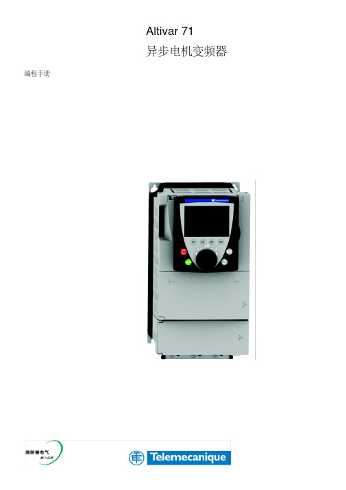
施耐德ATV71变频器调试指南第一部分接线一.电气控制图:1.主回路2.控制回路3.编码器二.端子位置图:1.功率端子分布:ATV71-HD95N4 ATV71-HD95N4(输入电抗器)ATV71-HD45N4/ ATV71-HD55N4 ATV71-HU75N4 2.控制端子位置图:3.编码器卡安装图三.接线注意事项:1.各功率端子和控制端子一定要安装紧固;1.1 动力直流母线端子PO--PA+之间的短接铜片一定要保持紧固;1.2 控制端子的PWR--+24V之间的短接片一定要保持连接,否则变频器将显示状态PRA并且不能正常输出。
1.3 如用AI1+和AI1-做双极性给定,请去掉AI1-和com之间的短接片。
2.请可靠连接各保护地和屏蔽地。
第二部分用中文图形终端编程一.中文图形编程操作终端界面二.菜单结构1.主菜单注:所有的参数调整都在1 变频器菜单中进行,其它的主菜单都是辅助功能。
这些需要在使用中灵活掌握,慢慢积累经验。
2.变频器菜单注:变频器菜单中有关调试主要菜单是1.1 到 1.8 。
我们暂时也仅仅涉及一些主要的菜单和参数。
其它都是辅助菜单,这些需要在使用中灵活掌握,慢慢积累经验。
三.调试的步骤第一步,设置简捷的起停控制设置端子与面板切换功能键(命令菜单):在命令菜单,找到最后一个参数:F4键分配:设置其功能为T/K,即为端子控制(Terminals)与图形终端控制(Kepad)切换。
这样按F4键可以切换用端子控制起停或图形终端控制起停。
端子控制有效时,起停命令来自LI1, LI2的逻辑端子的输入,这时变频器图形终端首行显示的第二个位置显示TERM;图形终端控制激活时,按图形终端上的RUN, STOP,FWD/REV键可以控制变频器的正反转,旋转导航键(浏览鼓轮)改变频率给定这时图形终端首行显示的第二个位置显示HMI。
此设置的目的是为了便于手动试运转。
正常运行时,应采用端子控制。
(常熟工厂为设置)。

施耐德ATV71变频器调试指南第一部分接线一.电气控制图:1.主回路2.控制回路3.编码器二.端子位置图:1.功率端子分布:ATV71-HD95N4 ATV71-HD95N4(输入电抗器)ATV71-HD45N4/ ATV71—HD55N4 ATV71-HU75N4 2.控制端子位置图:3.编码器卡安装图三.接线注意事项:1.各功率端子和控制端子一定要安装紧固;1.1 动力直流母线端子PO—-PA+之间的短接铜片一定要保持紧固;1.2 控制端子的PWR-—+24V之间的短接片一定要保持连接,否则变频器将显示状态PRA并且不能正常输出。
1.3 如用AI1+和AI1—做双极性给定,请去掉AI1-和com之间的短接片.2.请可靠连接各保护地和屏蔽地。
第二部分用中文图形终端编程一.中文图形编程操作终端界面二.菜单结构1.主菜单注:所有的参数调整都在 1 变频器菜单中进行,其它的主菜单都是辅助功能.这些需要在使用中灵活掌握,慢慢积累经验。
2.变频器菜单注:变频器菜单中有关调试主要菜单是1.1 到 1。
8 。
我们暂时也仅仅涉及一些主要的菜单和参数.其它都是辅助菜单,这些需要在使用中灵活掌握,慢慢积累经验.三.调试的步骤第一步,设置简捷的起停控制设置端子与面板切换功能键(命令菜单):在命令菜单,找到最后一个参数:F4键分配:设置其功能为 T/K,即为端子控制(Terminals)与图形终端控制(Kepad)切换。
这样按F4键可以切换用端子控制起停或图形终端控制起停。
端子控制有效时,起停命令来自LI1,LI2的逻辑端子的输入,这时变频器图形终端首行显示的第二个位置显示TERM;图形终端控制激活时,按图形终端上的RUN, STOP,FWD/REV键可以控制变频器的正反转,旋转导航键(浏览鼓轮)改变频率给定这时图形终端首行显示的第二个位置显示HMI。
此设置的目的是为了便于手动试运转.正常运行时,应采用端子控制。
(常熟工厂为设置)。
Product manual5114Programmable transmitterINTE RFACE S | COMMUNIC ATION INTE RFACE S | MULTIFUNC TIONAL | ISOL ATION | DISPL AYNo. 5114V108-UKFrom serial no. 1910530016 Product Pillars to meet your every needWith our innovative, patented technologies, we make signal conditioning smarter and simpler. Our portfolio is composed of six product areas, where we offer a wide range of analog and digital devices covering over a thousand applications in industrial and factory automation. All our products comply with or surpass the highest industry standards, ensuring reliability in even the harshest of environments and have a 5-year warranty for greater peace of mind.Individually outstanding, unrivalled in combinationOur range of temperature transmitters and sensors provides the highest level of signal integrity from the measurement point to your control system. You can convert industrial process temperature signals to analog, bus or digital communications using a highly reliable point-to-point solution with a fast response time, automatic self-calibration, sensor error detection, low drift, and top EMC performance in any environment.Our unique range of single devices covering multiple applications is easily deployable as your site standard. Having one variant that applies to a broad range of applications can reduce your installation time and training, and greatly simplify spare parts management at your facilities. Our devices are designed for long-term signal accuracy, low power consumption, immunity to electrical noise and simple programming.We provide inexpensive, easy-to-use, future-ready communication interfaces that can access your PR installed base of products. All the interfaces are detachable, have a built-in display for readout of process values and diagnostics, and can be configured via push-buttons. Product specific functionality includes communication via Modbus and Bluetooth and remote access using our PR Process Supervisor (PPS) application, available for iOS and Android.Our display range is characterized by its flexibility and stability. The devices meet nearly every demand for display readout of process signals and have universal input and power supply capabilities. They provide a real-time measurement of your process value no matter the industry and are engineered to provide a user-friendly and reliable relay of information, even in demanding environments.We deliver the safest signals by validating our products against the toughest safety standards. Through our commitment to innovation, we have made pioneering achievements in developing I.S. interfaces with SIL 2 Full Assessment that are both efficient and cost-effective. Our comprehensive range of analog and digital intrinsically safe isolation barriers offers multifunctional inputs and outputs, making PR an easy-to-implement site standard. Our backplanes further simplify large installations and provide seamless integration to standard DCS systems.Our compact, fast, high-quality 6 mm isolators are based on microprocessor technology to provide exceptional performance and EMC-immunity for dedicated applications at a very low total cost of ownership. They can be stacked both vertically and horizontally with no air gap separation between units required.Programmable transmitter5114Table of contentsWarning (4)Symbol identification (4)Safety instructions (5)How to demount system 5000 (6)Application (7)Technical characteristics (7)Input types (7)Output (8)Configuration (8)Electrical specifications (8)Order (12)5114 connection to Loop Link (12)Block diagram (13)Selection of input type (5114A) (14)Document history (15)5114V108-UK 34 5114V108-UK WarningThis device is designed for connection to hazardous electric voltages.Ignoring this warning can result in severe personal injury or mechanical damage.To avoid the risk of electric shock and fire, the safety instructions of this manual must be observed and the guidelines followed.The specifications must not be exceeded, and the device must only be applied as described in the following.Prior to the commissioning of the device, this manual must be examined carefully.Only qualified personnel (technicians) should install this device.If the equipment is used in a manner not specified by the manufacturer, the protection provided by the equipment may be impaired. Warning Until the device is fixed, do not connect hazardous voltages to the device.The following operations should only be carried out on a disconnected device and under ESD-safe conditions: Dismantlement of the device for setting of DIP-switches and jumpers. General mounting, wire connection and disconnection. Troubleshooting the device. Repair of the device and replacement of circuit breakers must be done by PR electronics A/S only.Warning SYSTEM 5000 must be mounted on a DIN rail according to DIN 60715.The communication connector of SYSTEM 5000 is connected to the input terminals on which dangerous voltages can occur, and it must only be connected to the programming unit Loop Link by way of the enclosed cable.Symbol identification Triangle with an exclamation mark: Read the manual before installation and commissioning of the device in order to avoid incidents that could lead to personal injury or mechanical damage. Warning / demand. Potentially lethal situations.The CE mark proves the compliance of the device with the essential requirements of the directives. The double insulation symbol shows that the device is protected by double or reinforced insulation. Ex devices have been approved acc. to the ATEX directive for use in connection with installations in explosive areas.HAZARD-OUSVOLTAGEINSTAL-LATIONGENERALSafety instructionsDefinitionsHazardous voltages have been defined as the ranges: 75 to 1500 Volt DC, and 50 to 1000 Volt AC.Technicians are qualified persons educated or trained to mount, operate, and also trouble-shoot technically correct and in accordance with safety regulations.Operators, being familiar with the contents of this manual, adjust and operate the knobs or potentiometers during normal operation.Receipt and unpackingUnpack the device without damaging it and check whether the device type corresponds to the one ordered. The packing should always follow the device until this has been permanently mounted.EnvironmentAvoid direct sun light, dust, high temperatures, mechanical vibrations and shock, and rain and heavy moisture. If necessary, heating in excess of the stated limits for ambient temperatures should be avoided by way of ventilation.The device must be installed in pollution degree 2 or better.The device is designed to be safe at least under an altitude up to 2 000 m.The device is designed for indoor use.MountingOnly technicians, who are familiar with the technical terms, warnings, and instructions in the manual and who are able to follow these, should connect the device. Should there be any doubt as to the correct handling of the device, please contact your local distributor or, alternatively,PR electronics A/SMounting and connection of the device should comply with national legislation for mounting of electric materials, i.e. wire cross section, protective fuse, and location.Stranded wire should be installed with an insulation stripping length of 5 mm or via a suitable insulated terminal such as a bootlace ferrule.Descriptions of input / output and supply connections are shown in the block diagram and side label.The following apply to fixed hazardous voltages-connected devices:T he max. size of the protective fuse is 10 A and, together with a power switch, it should be easily accessible and close to the device. The power switch should be marked with a label telling it will switch off the voltage to the device.Year of manufacture can be taken from the first two digits in the serial number.Calibration and adjustmentDuring calibration and adjustment, the measuring and connection of external voltages must be carried out according to the specifications of this manual. The technician must use tools and instruments that are safe to use.Normal operationOperators are only allowed to adjust and operate devices that are safely fixed in panels, etc., thus avoiding the danger of personal injury and damage. This means there is no electrical shock hazard, and the device is easily accessible.CleaningWhen disconnected, the device may be cleaned with a cloth moistened with distilled water.LiabilityTo the extent the instructions in this manual are not strictly observed, the custom e r cannot advance a demand against PR electronics A/S that would otherwise exist according to the concluded sales agreement.5114V108-UK 56 5114V108-UKHow to demount system 5000First, remember to demount the connectors with hazardous voltages.Picture 1:By lifting the bottom lock, the device is detached from the DIN rail.Picture 2:By lifting the upper lock and pulling the front plate simultaneouslythe PCB can be removed Switches and jumpers can now be adjusted.Picture 3:Access to programming connectorProgrammable transmitter 5114• Input for RTD, TC, mV, linear resistance, mA, and V• 3-port 3.75 kVAC galvanic isolation• Current and voltage output• Universal voltage supply• 1- and 2-channel versions• Loop supply > 17.1 V in Ex zone 0ApplicationElectronic temperature measurement with resistance sensor or thermocouple sensor. • Ex barrier for temperature sensors, potentiometers, and current / voltage signals • Ex power supply for 2-wire transmitters in zone 0, 1, 2, 20, 21, and 22.• Amplification of mV signals. • Conversion of linear resistance variation. • Galvanic isolation of analogue signals.• Measurement of floating signals. • Linearisation of non-linear Ohm, mV, mA, or voltage signals. • Separation of circuits in PELV/SELV installations. • The transmitter is especially suitable for emitting the output current signal, either as a standard current signal or as a loop signal.Technical characteristicsThe unit is based on a microprocessor core with an efficient program operation. The basic calibration data and present set-up are stored in an EEPROM thereby avoiding the loss or change of data at power off. The 2-channel version has a full galvanic isolation between the channels. By way of jumpers on the PCB the input in the standard version can be programmed either for a temperature or a current / voltage input. This means that one channel can work as for instance a temperature transmitter and the other can work as an isolation amplifier. Measurement range, signal parameters, and output span are configured to the present task by way of a PC and PR electronics A/S’ communica t ions interface Loop Link.Input typesTemperature input - jumpers in position 1Thermocouple input (TC) for standard thermocouples type B, E, J, K, L, N, R, S, T, U, W3, W5, LR according to the norms IEC 584, DIN 43710, ASTM E988-90 and GOST 3044-84. The CJC can be selected in 3 different ways: internally in the terminal, externally by way of a Pt100 / Ni100 sensor, or externally with a constant temperature.If internal compensation is selected, a terminal with a built-in temperature sensor must be ordered separately (PR type no. 5910 and 5913). Sensor error detection is available.RTD input for Pt100...Pt1000 according to the norm IEC 751 and Ni100...Ni1000 according to the norm DIN 43760. Automatic cable compensation at a 3- or 4-wire connection. At a 2-wire connection the cable resistance can be entered or measured by the configuration program and sent to the device which then compensates by the entered cable resistance. Sensor error detection is available.Resistance input for resistance measurement with cable compensation as described under the RTD input. Sensor error detection is available.The mV input is programmable in the range -150...+150 mV.Current / voltage input - jumpers in position 2The current input is programmable in the range 0...100 mA, for instance 4...20 mA.The voltage input is programmable in the range 0...250 VDC.Auxiliary supplies are selected in the configuration program:Loop transmitter supply > 17.1 VDC.Reference voltage of 2.5 VDC, for instance as a supply for potentiometers.5114V108-UK 7OutputThe analogue standard current / voltage output is programmable in the range 0...20 mA, for instance 4...20 mA and 0 (10)VDC. The output voltage can be ordered for a maximum of 12 VDC by a special shunt resistance. The output signal is proportional and linear to the value of the input signal. Special set-ups can be selected in the configuration program, for instance a customised linearisation, a reversed output, a limiter according to the selected output span, and selection of an output value in case of a sensor error. Maximum load on the current output is 600 Ω. Minimum load on the voltage output is 500 kΩ.Loop 4...20 mA current outputBy wiring the current signal alternatively, the output works as a loop output. If the supply voltage for the 5114 disappears, the output current drops to < 4 mA.Sensor error detectionThe output can be set up at an RTD, thermocouple and linear resistance input to go to max., to min. or entered value at sensor error detection. If the output is set to 4…20 mA it is also possible to select NAMUR NE43 Upscale or Downscale. ConfigurationThe transmitter is configured to the present task by way of a PC and PR electronics A/S’ communications interface Loop Link. The communications interface is galvanically isolated to protect the PC port. Communication is 2-way to allow the retrieval of the transmitter set-up into the PC and to allow the transmission of the PC set-up to the transmitter. For users who do not wish to do the set-up them s elves, the 5114 can be delivered configured according to customer specifica t ions: input type, measurement range, sensor error detection, and output signal.Electrical specificationsEnvironmental conditionsOperating temperature . . . . . . . . . . . . . . . . . . . . . . . . . . . . . . . . -20°C to +60°CCalibration temperature. . . . . . . . . . . . . . . . . . . . . . . . . . . . . . . . 20...28°CRelative humidity . . . . . . . . . . . . . . . . . . . . . . . . . . . . . . . . . . . < 95% RH (non-cond.)Protection degree................................... IP20Mechanical specificationsDimensions (HxWxD) . . . . . . . . . . . . . . . . . . . . . . . . . . . . . . . . . 109 x 23.5 x 130 mmDIN rail type. . . . . . . . . . . . . . . . . . . . . . . . . . . . . . . . . . . . . . . DIN EN 60715 - 35 mm Weight.......................................... 225 gWire size (min....max.)................................. 0.13...2.08 mm2 AWG 26...14 stranded wireScrew terminal torque. . . . . . . . . . . . . . . . . . . . . . . . . . . . . . . . . 0.5 NmVibration. . . . . . . . . . . . . . . . . . . . . . . . . . . . . . . . . . . . . . . . . IEC 60068-2-62...13.2 Hz . . . . . . . . . . . . . . . . . . . . . . . . . . . . . . . . . . . . . . ±1 mm13.2...100 Hz. . . . . . . . . . . . . . . . . . . . . . . . . . . . . . . . . . . . . ±0.7 gCommon specificationsSupply voltage, universal. . . . . . . . . . . . . . . . . . . . . . . . . . . . . . . 21.6...253 VAC, 50...60 Hzor 19.2...300 VDCFuse . . . . . . . . . . . . . . . . . . . . . . . . . . . . . . . . . . . . . . . . . . . 400 mA SB / 250 VACMax. required power, 1 / 2 channels . . . . . . . . . . . . . . . . . . . . . . . . 2.1 W / 2.8 WMax. power dissipation................................ 2.0 WMax. required power is the maximum power needed at terminals 31 and 33.Max. power dissipation is the maximum power dissipated by the device.Isolation voltage, test / operation. . . . . . . . . . . . . . . . . . . . . . . . . . 3.75 kVAC / 250 VACPELV/SELV. . . . . . . . . . . . . . . . . . . . . . . . . . . . . . . . . . . . . . . . IEC 61140 Programming...................................... Loop LinkSignal / noise ratio. . . . . . . . . . . . . . . . . . . . . . . . . . . . . . . . . . . Min. 60 dB (0...100 kHz)Updating time:Temperature input. . . . . . . . . . . . . . . . . . . . . . . . . . . . . . . . . . 115 msmA / V / mV input.................................. 75 ms8 5114V108-UK5114V108-UK 9Response time (0...90%, 100...10%), programmable:Temperature input. . . . . . . . . . . . . . . . . . . . . . . . . . . . . . . . . . 400 ms...60 smA / V / mV input .................................. 250 ms...60 sSignal dynamics, input . . . . . . . . . . . . . . . . . . . . . . . . . . . . . . . . 22 bitSignal dynamics, output . . . . . . . . . . . . . . . . . . . . . . . . . . . . . . . 16 bitAccuracy, the greater of the general and basic values:Auxiliary supplies:Reference voltage ................................... 2.5 VDC ±0.5% / 15 mA 2-wire supply (pin 44...42 and 54...52). . . . . . . . . . . . . . . . . . . . . . . 28...17.1 VDC / 0...20 mA Electrical specifications, temperature input TC inputType Min. value Max. value Min. span StandardB E J K L N R S T U W3W5LR +400°C -100°C -100°C -180°C -100°C -180°C -50°C -50°C -200°C -200°C 0°C 0°C -200°C +1820°C +1000°C +1200°C +1372°C +900°C +1300°C +1760°C +1760°C +400°C +600°C +2300°C +2300°C +800°C 200°C 50°C 50°C 50°C 50°C 100°C 200°C 200°C 50°C 75°C 200°C 200°C 50°C IEC 60584-1IEC 60584-1IEC 60584-1IEC 60584-1DIN 43710IEC 60584-1IEC 60584-1IEC 60584-1IEC 60584-1DIN 43710ASTM E988-90ASTM E988-90GOST 3044-84Max. offset . . . . . . . . . . . . . . . . . . . . . . . . . . . . . . . . . . . . . . . 50% of selec. max. value Sensor error current .................................. Nom. 30 µACJC . . . . . . . . . . . . . . . . . . . . . . . . . . . . . . . . . . . . . . . . . . . . ≤ ±1°CSensor error detection . . . . . . . . . . . . . . . . . . . . . . . . . . . . . . . . Yes EMC - immunity influence. . . . . . . . . . . . . . . . . . . . . . . . . < ±0.5% of spanExtended EMC immunity:NAMUR NE 21, A criterion, burst . . . . . . . . . . . . . . . . . . . . < ±1% of spanGeneral valuesInput type Absolute accuracy Temperature coefficientAll ≤ ±0.05% of span ≤ ±0.01% of span / °CBasic valuesInput type Basic accuracy Temperature coefficientmA ≤ ±4 μA ≤ ±0.4 μA / °CVolt ≤ ±10 μV ≤ ±1 μV / °CRTD ≤ ±0.2°C ≤ ±0.01°C / °CLin. R ≤ ±0.1°Ω≤ ±10 mΩ / °CTC type:E, J, K, L, N, T, U ≤ ±1°C≤ ±0.05°C / °CTC type: B, R, S, W3, W5, LR ≤ ±2°C≤ ±0.2°C / °CmV inputMeasurement range.................................. -150...+150 mVMin. measurement range............................... 5 mVMax. offset . . . . . . . . . . . . . . . . . . . . . . . . . . . . . . . . . . . . . . . 50% of selec. max. value Input resistance . . . . . . . . . . . . . . . . . . . . . . . . . . . . . . . . . . . . Nom. 10 MΩRTD and linear resistance inputInput type Min. value Max. value Min. span StandardPt100Ni100 Linear resist.-200°C-60°C0 Ω+850°C+250°C5000 Ω25°C25°C30 ΩIEC 60751DIN 43760-Max. offset . . . . . . . . . . . . . . . . . . . . . . . . . . . . . . . . . . . . . . . 50% of selec. max. value Max. cable resistance per wire. . . . . . . . . . . . . . . . . . . . . . . . . . . . 10 ΩSensor current..................................... Nom. 0.2 mAEffect of sensor cable resistance, (3- / 4-wire).................. < 0.002 Ω / ΩSensor error detection . . . . . . . . . . . . . . . . . . . . . . . . . . . . . . . . YesElectrical specifications, mA / V / mV inputCurrent inputMeasurement range.................................. 0...100 mAMin. measurement range (span). . . . . . . . . . . . . . . . . . . . . . . . . . . 4 mAMax. offset . . . . . . . . . . . . . . . . . . . . . . . . . . . . . . . . . . . . . . . 50% of selec. max. value Input resistance:Supplied unit..................................... nom. 10 Ω + PTC 10 ΩNon-supplied unit.................................. R SHUNT = ∞, V DROP < 6 V Voltage inputMeasurement range.................................. 0...250 VDCMin. measurement range (span). . . . . . . . . . . . . . . . . . . . . . . . . . . 5 mVDCMax. offset . . . . . . . . . . . . . . . . . . . . . . . . . . . . . . . . . . . . . . . 50% of selec. max. value Input resistance ≤ 2.5 VDC............................. Nom. 10 MΩ> 2.5 VDC............................. Nom. 5 MΩElectrical specifications - OUTPUTCurrent outputSignal range (span) . . . . . . . . . . . . . . . . . . . . . . . . . . . . . . . . . . 0...20 mAMin. signal range (span). . . . . . . . . . . . . . . . . . . . . . . . . . . . . . . . 10 mAMax. offset . . . . . . . . . . . . . . . . . . . . . . . . . . . . . . . . . . . . . . . 50% of selec. max. value Load . . . . . . . . . . . . . . . . . . . . . . . . . . . . . . . . . . . . . . . . . . . ≤ 600 ΩLoad stability...................................... ≤ 0.01% of span / 100 ΩCurrent limit. . . . . . . . . . . . . . . . . . . . . . . . . . . . . . . . . . . . . . . ≤ 28 mAVoltage outputSignal range (span) . . . . . . . . . . . . . . . . . . . . . . . . . . . . . . . . . . 0...10 VDCMin. signal range (span). . . . . . . . . . . . . . . . . . . . . . . . . . . . . . . . 500 mVMax. offset . . . . . . . . . . . . . . . . . . . . . . . . . . . . . . . . . . . . . . . 50% of selec. max. value Load . . . . . . . . . . . . . . . . . . . . . . . . . . . . . . . . . . . . . . . . . . . ≥ 500 kΩ2-wire 4...20 mA outputSignal range. . . . . . . . . . . . . . . . . . . . . . . . . . . . . . . . . . . . . . . 4...20 mALoad stability...................................... ≤ 0.01% of span / 100 ΩLoad resistance. . . . . . . . . . . . . . . . . . . . . . . . . . . . . . . . . . . . . ≤ (V supply-3.5) / 0.023 A [Ω] Max. external 2-wire supply............................. 29 VDCEffect of external 2-wire supply voltage change. . . . . . . . . . . . . . . . . < 0.005% of span / V Sensor error detectionProgrammable . . . . . . . . . . . . . . . . . . . . . . . . . . . . . . . . . . . . . 0...23 mANAMUR NE43 Upscale . . . . . . . . . . . . . . . . . . . . . . . . . . . . . . . . 23 mANAMUR NE43 Downscale. . . . . . . . . . . . . . . . . . . . . . . . . . . . . . . 3.5 mANo function....................................... Not definedOf span = Of the presently selected range10 5114V108-UKEx / I.S. data for 5114B, all typesTerminal 31, 32, and 33U m . . . . . . . . . . . . . . . . . . . . . . . . . . . . . . . . . . . . . . . . . . . . 250 VEx / I.S. data for 5114 B1 (channel 1 for 5114B3)Terminal 41, 42, 44 to 43 (51, 52, 54 to 53)U o. . . . . . . . . . . . . . . . . . . . . . . . . . . . . . . . . . . . . . . . . . . . . 7.5 VDCI o............................................. 6.0 mADCP o. . . . . . . . . . . . . . . . . . . . . . . . . . . . . . . . . . . . . . . . . . . . . 11.25 mWL o. . . . . . . . . . . . . . . . . . . . . . . . . . . . . . . . . . . . . . . . . . . . . 200 mHC o. . . . . . . . . . . . . . . . . . . . . . . . . . . . . . . . . . . . . . . . . . . . . 6.0 μFEx / I.S. data for 5114 B2 (channel 2 for 5114B3)Terminal 44 to 41 (54 to 51)U o. . . . . . . . . . . . . . . . . . . . . . . . . . . . . . . . . . . . . . . . . . . . . 28 VDCI o............................................. 87 mADCP o. . . . . . . . . . . . . . . . . . . . . . . . . . . . . . . . . . . . . . . . . . . . . 0.62 WL o. . . . . . . . . . . . . . . . . . . . . . . . . . . . . . . . . . . . . . . . . . . . . 4.2 mHC o. . . . . . . . . . . . . . . . . . . . . . . . . . . . . . . . . . . . . . . . . . . . . 0.08 μFTerminal 42, 43 to 41 (52, 53 to 51)U o. . . . . . . . . . . . . . . . . . . . . . . . . . . . . . . . . . . . . . . . . . . . . 7.5 VDCI o............................................. 6.0 mADCP o. . . . . . . . . . . . . . . . . . . . . . . . . . . . . . . . . . . . . . . . . . . . . 11.25 mWL o. . . . . . . . . . . . . . . . . . . . . . . . . . . . . . . . . . . . . . . . . . . . . 200 mHC o. . . . . . . . . . . . . . . . . . . . . . . . . . . . . . . . . . . . . . . . . . . . . 6.0 μFObserved authority requirementsEMC. . . . . . . . . . . . . . . . . . . . . . . . . . . . . . . . . . . . . . . . . . . . 2014/30/EULVD. . . . . . . . . . . . . . . . . . . . . . . . . . . . . . . . . . . . . . . . . . . . 2014/35/EU ATEX........................................... 2014/34/EU RoHS........................................... 2011/65/EUApprovalsDet Norske Veritas, Ships & Offshore. . . . . . . . . . . . . . . . . . . . . . . . TAA0000101EAC. . . . . . . . . . . . . . . . . . . . . . . . . . . . . . . . . . . . . . . . . . . . TR-CU 020/2011I.S. / Ex approvals ATEX........................................... DEMKO 99ATEX124571EAC Ex TR-CU 012/2011. . . . . . . . . . . . . . . . . . . . . . . . . . . . . . . RU C-DK.HA65.B.00355/195114V108-UK 1112 5114V108-UKOrderExample: 5114B3BNB! For TC inputs with internal CJC, remember to order the CJC connectors type 5910 / 5910 Ex (ch. 1) and 5913 / 5913 Ex (ch. 2).TypeVersion Input Channels 5114Standard: A RTD / TC / R / mA / V / mV : -Single Double : A : BATEX Ex : B RTD / TC / mV / RmA / V / mVChannel 1, RTD / TC / mV / RChannel 2, mA / V / mV : 1: 2: 35114 connection to Loop Link5114V108-UK 13Block diagram* A c c e s s o r i e s : 5910 C J C c o n n e c t o r C H 1, 5913 C J C c o n n e c t o r C H 2.C h a n n e l1 s h o w n a saSelection of input type (5114A) Input JP 1JP 2JP 3JP 4Temperature channel 1 Temperature channel 21-1--1-1Current / voltage channel 1 Current / voltage channel 22-2--2-214 5114V108-UKDocument historyThe following list provides notes concerning revisions of this document.Rev. ID Date Notes108 2208 Safety instructions updated acc. to LVD.5114V108-UK 15Benefit today from PERFORMANCE MADE SMARTER。
Schneider Electric China 北京市朝阳区望京东路Schneider Electric Building, No. 6, 由于标准和材料的变更,文中所述特性和本资料中的图像只有经过我们
ATV-IMC 内置可编程控制卡
方寸之间 智显神通
用于ATV71和ATV61变频器
施耐德电气
6号施耐德电气大厦邮编: 100102
电话: (010) 8434 6699传真: (010) 8450 1130
East WangJing Rd., C haoyang District Beijing 100102 P.R.C.Tel: (010) 8434 6699Fax: (010) 8450 1130
的业务部门确认以后,才对我们有约束。
本手册采用生态纸印刷
2010.09
SCDOC 1437
施耐德电气版权所有
客户关爱中心热线:400 810 1315
推广手册
施耐德电气(中国)投资有限公司
施耐德电气(中国)投资有限公司 北京市朝阳区望京东路6号施耐德电气大厦
邮编:100102
电话:(010) 84346699 传真:(010) 84501130■ 施耐德电气中国研修学院
北京市朝阳区望京东路6号施耐德电气大厦
邮编:100102
电话:(010) 84346699
传真:(010) 84501130。
施耐德变频器和编码器卡配套使用调试PLC:MICRO3721CANOPEN主站卡:PCMIC110卡变频器3台:ATV71HU75N4两台和ATV71H075N4,EDS文件是1.2版本的触摸屏:XTBGT2120这个客户是新开发的客户,需求很紧急,要求尽快供货,尽快调试,他们的机器好用起来,因为当时401卡缺货,就改用有现货的403卡,403卡是接受12V集电极开路输出编码器信号的卡,因电机和编码器是配套的,时间很晚了,供货商没有留下任何资料就走了(深圳回东莞)我在CAN通讯都做好演示程序的情况下,到现场装机调试71的闭环控制,主要是编码器的问题,以前调试过几次401卡(5V,422或差分输出的编码器信号),以为接线和以前一样,结果反复查线,调试,总是报故障,SPF--检测不到编码器信号,因时间太晚,在CANOPEN通讯正常之后,计划明天再试编码器卡第二天,经多方联系,发现403卡的应用不多,经刘老师,张超的提示,可能是编码器是NPN的,而我们的默认接法是按PNP的,经询问,果然是欧姆龙的编码器是NPN的,具体对应关系为:PNP: A----------------------------------------------AB-----------------------------------------------BA----------------------------------------------A-B----------------------------------------------B-0V--------------------------------------------0V+V--------------------------------------------Vs+编码器侧编码器卡侧如果编码器没有A-和B-,就把编码器卡侧的A-和B-和OV短接起来然后把编码器的脉冲数和脉冲类型设置后,把ENC设置为YES,然后启动变频器,如果电机旋转20秒左右,没有报警的话,应该是没有问题的,检查ENC的内容,应该是DONE,说明变频器已经认出编码器,并且反馈良好,如果报警,有可能是A和B反了,把A和B对调即可。