UW-500600介绍
- 格式:doc
- 大小:1.00 MB
- 文档页数:2

LBI-38904BMaintenance ManualORION™UHFSCAN AND SYSTEMMOBILE RADIOTABLE OF CONTENTSSynthesizer/Receiver/Exciter . . . . . . . LBI-39033Power Amplifier . . . . . . . . . . . . . . LBI-39034PA Interface . . . . . . . . . . . . . . . . LBI-38994Control Logic/IF Board . . . . . . . . . . LBI-38907Control Units . . . . . . . . . . . . . . . LBI-38992Assemblies . . . . . . . . . . . . . . . . LBI-38909Service Section . . . . . . . . . . . . . . LBI-38908Ericsson Inc.Private Radio SystemsMountain View RoadLynchburg, Virginia 24502ericssonz1-800-528-7711 (Outside USA, 804-528-7711)Printed in U.S.A.Copyright© October 1993, Ericsson GE Mobile Communications Inc.SPECIFICATIONS*Frequency Range:403-440 MHz 440-470 MHz 470-512 MHzRegulatory ApprovalFCC (United States)AXATR-315-A2403-440 MHz 20/40 Watts AXATR-315-B2440-470 MHz 30/40 Watts AXATR-315-C2470-512 MHz 35 Watts AXATR-316-A2403-440 MHz 100 Watts AXATR-316-B2440-470 MHz 100 Watts AXATR-316-C2470-512 MHz 80 Watts DOC (Canada)TR-315TR-315403-440 MHz 20/40 Watts 440-470 MHz30/40 WattsBattery Drain:ReceiveSquelched 1.1 Amperes at 13.8 V oltsUnsquelched 3.0 Amperes at 13.8 V olts (15 Watts Output)Transmitter20 Watts 35/40 Watts 80/100 Watts12 Amperes at 13.2 V olts 14 Amperes at 13.6 V olts 25/28 Amperes at 13.4 V olts Frequency Stability:0.0002% depending on model Temperature Range:-30° C (-22° F) to +60° C (+140° F)Duty Cycle:100% Receive, 14% Transmit TransmitterTransmit Output Power:20W/35W/40W/80W/100W Conducted Spurious:-85 dB Modulation:±4.5 kHzAudio Sensitivity:55 to 110 millivoltsAudio Frequency Characteristics:Within +1 dB to -3 dB of a 6 dB/octave pre-emphasis 300 Hz and within +1 dB to -4.5 dB of a 6 dB/octave pre-emphasis 3000 Hz per EIA standards. Post-limiter filter per FCC and EIA.Distortion:Less than 2% (1000 Hz)Less than 5% (3000 Hz)Deviation Symmetry:0.3 kHz maximum Maximum Frequency Separation:403-440 MHz 37 MHz 440-470 MHz 30 MHz 470-512 MHz 42 MHz Microphone Load Impedance:600 OhmsPower Adjust Range:100% to 50% of rated power (U.S.A. Models)100% to 30% of rated power (Euro Models)RF Output Impedance:50 Ohms FM Noise:45 dBContinuedThis manual covers Ericsson and General Electric products manufactured and sold by Ericsson Inc.NOTICE!Repairs to this equipment should be made only by an authorized service technician or facility designated by the supplier.Any repairs, alterations or substitution of recommended parts made by the user to this equipment not approved by the manufacturer could void the user’s authority to operate the equipment in addition to the manufacturer’s warranty.NOTICE!This manual is published by Ericsson Inc., without any warranty. Improvements and changes to this manual necessitated by typographical errors, inaccuracies of current information, or improvements to programs and/or equipment, may be made by Ericsson Inc., at any time and without notice. Such changes will be incorporated into new editions of this manual. No part of this manual may be reproduced or transmitted in any form or by any means, electronic or mechanical, including photocopying and recording, for any purpose, without the express written permission of Ericsson Inc.The software contained in this device is copyrighted by the Ericsson Inc. Unpublished rights are reserved under the copyright laws of the United States.NOTICE!LBI-389041DESCRIPTIONThe synthesized ORION mobile radio combinations are completely solid-state, utilizing microcomputer technology and integrated circuits to provide high-quality, high-reliabil-ity radios. Standard combinations may be equipped with:•Microcomputer Controlled Frequency Synthesizer•Up to 16 Channels•0.0002% Frequency Stability•Other Structured OptionsThe basic radio consists of three printed wiring boards mounted in a cast aluminum frame. The three boards are:1.The Control Logic/IF board2.The Frequency Synthesizer/Receiver/Exciter board3.The Power Amplifier boardThe radio is of double-layer construction with tuning ad-justments easily accessible from the top of the radio.The Control Logic/IF Board is located on the top of theradio, while the Power Amplifier and the Synthesizer/Re-ceiver/Exciter boards are located on the bottom of the radio.SYNTHESIZER/INTERCONNECTThe synthesizer consists of a microcomputer, E lectricallyE rasable P rogrammable R ead O nly M emory (EEPROM), afrequency synthesizer IC, transmit and receive V oltage C on-trolled O scillator’s (VCO) and associated circuitry. The fre-quency synthesizer under control of the microcomputergenerates all transmit and receive Radio Frequencies (RF).The EEPROM stores binary data for all radio frequen-cies, Channel Guard tones/digital codes and the timing func-tion of the C arrier C ontrol T imer (CCT). Themicrocomputer accesses the EEPROM and provides the correctW ALSH bits to the Channel Guard circuitry to generate thecorrect Channel Guard tone or digital code on a per-channelbasis.PROGRAMMINGThe EEPROM allows the radio to be programmed or repro-grammed as needed to adapt to changing system requirements.Radio Frequencies, Channel Guard tone and digital codes andthe CCT function can be reprogrammed.The EEPROM can be reprogrammed through the radiofront connector using a personal computer. This programmerallows all information to be loaded simultaneously.Programming instructions are provided in the respectiveProgrammer Maintenance Manuals.TRANSMITTERThe transmitter consists of the exciter, frequency synthe-sizer, transmitter VCO and a Power Amplifier (PA) assembly.The PA assembly consists of a PA board mounted on a heatsink assembly. The PA board also contains an antenna switch-ing diode and a low-pass filter.Audio and Channel Guard circuitry for the transmitter is lo-cated on the Control Logic/IF Board.RECEIVERThe receiver consists of the frequency synthesizer, RXVCO, injection amplifiers, front end, IF and limiter detector.Audio, squelch and Channel Guard circuitry for the receiver islocated on the Control Logic/IF Board.SYSTEM CONTROL FUNCTIONA microprocessor on the Control Logic/IF board controlsthe frequency synthesizer, the TX ON/OFF, the decoding ofCTCSS tones, the generation of CTCSS tones,... etc. The audioprocessor circuitry of the transmitter and the receiver are lo-cated on the Control Logic/IF board. Squelch circuitry and aconnection to the digital AEGIS circuit is also located on theControl Logic/IF board.OPERATIONComplete operating instructions for the ORION Two-WayRadio are provided in Operator’s Manual LBI-38888 for thecontrol unit used.MAINTENANCEThe Service Section in maintenance manual LBI-38908contains the maintenance information to service this radio. TheService Section includes:•Dissassembly Procedures•Replacement of IC’s, chip capacitors and resistors•Alignment procedures for the transmitter and receiver•Troubleshooting Procedures and wave formsA mechanical layout for the radio is found in ORION As-semblies Maintenance Manual LBI-38909.Figure 1 - ORION Mobile RadioSPECIFICATIONS* - Cont.ReceiverAudio Output:15 Watts with less than 3% distortion(To 4.0 ohm speaker)Sensitivity:0.35 µV (STD)/0.22 µV (PRE)12 dB SINAD (IEIA method)Selectivity:-85 dB (STD)-80 dB (PRE)EIA Two-Signal Method(25 kHz Channels)Spurious Response:-100 dB (STD)/-90 (PRE)Intermodulation 25 kHz:-85 dB (STD)/-80 dB (PRE)Maximum Frequency Separation:403-440 MHz .... 37 MHz440-470 MHz .... 30 MHz470-512 MHz .... 42 MHzFrequency Response:Within +1, -3 dB of 6 dB/octave de-emphasis from 300 to 3000MHz (1000 Hz reference)RF Input Impedance:50 OhmsHum/Noise ratio:Unsquelched-50 dBSquelched-70 dBChannel Spacing:30 kHz*These specifications are intended primarily for use of the service technician. Refer to the appropriate Specifications Sheet for the complete specifications.LBI-389042SYSTEM INTERCONNECTION DIAGRAMLBI-38904 Array U.S.A. LOW POWER3SYSTEM INTERCONNECTION DIAGRAM LBI-38904U.S.A. HIGH POWER4SYSTEM INTERCONNECTION DIAGRAMLBI-38904 Array EUROPEAN5。

中兴通讯电源产品技术经理培训教材本部事业部电源系统部二00二年四月目录第一章中兴电源产品部简介 (1)一、中兴通讯电源产品部发展概括 (1)二、中兴通信电源产品种类 (2)第二章通信电源基础知识 (6)第一讲通信电源发展概况 (6)一、通信电源的现状和发展趋势 (6)二、通信设备对电源系统的一般要求 (9)第二讲组合通信电源系统结构及功能 (10)第三章中兴通信电源产品特色 (15)第一讲中兴整流器技术 (15)一、工作基本原理 (15)二、中兴整流器技术特点 (16)第二讲中兴组合电源系统特点 (18)可靠的三级防雷网络 (19)自下而上全分布式的三级监控网络 (20)完善的蓄电池管理 (22)灵活多样的组网方式 (22)第三讲组网方式 (23)第四章中兴组合通信电源产品系列介绍 (27)第一讲ZXD5000 100A整流模块及其组成的电源系统 (27)一、ZXD5000 100A整流模块介绍 (27)二、ZXDU3000、ZXDU1500通讯电源系统简介 (29)第二讲ZXD2400 50A整流模块及其组成的电源系统 (32)一、ZXD2400 50A整流模块介绍 (33)二、ZXDU600E、ZXDU400通讯电源系统简介 (34)第三讲ZXD1500 30A整流模块及其组成的电源系统 (37)一、ZXD1500 30A整流模块介绍 (37)二、ZXDU300(2米高机柜)ZXDU300(1.6米高机柜) 通讯电源系统简介 (39)第四讲ZXD800E 15A整流模块及其组成的电源系统 (41)一、ZXD800E 15A整流模块介绍 (41)二、ZXDU150、ZXDU75、ZXDU45通讯电源系统简介 (43)第五讲+24V组合通信电源系统 (46)第五章中兴UPS产品介绍 (47)ZXUPS S501 (47)ZXUPS S502 (48)ZXUPS S503 (48)ZXUPS S506 (48)ZXUPS S510 (49)ZXUPS M510 (49)ZXUPS M515 (49)ZXUPS M520 (50)ZXUPS M530 (50)ZXUPS L005 (50)ZXUPS L006 (50)第六章通信电源计算配置方法 (52)第七章通信电源市场概述 (55)第一讲国内主要通信电源厂家及其产品特色 (55)一、华为公司 (55)公司背景 (55)产品系列 (56)产品技术特点 (56)我司对策 (57)二、武汉洲际通信电源集团有限公司 (57)公司背景 (57)产品特点 (57)我司对策 (58)三、中达-斯米克电器电子有限公司 (58)公司背景 (58)产品系列 (58)与我司技术优、劣势对比 (59)我司对策 (59)四、珠江电信设备制造有限公司 (59)公司背景 (59)产品系列 (59)产品技术特点 (60)五、新西兰SWITCHTEC公司 (60)公司简介 (60)产品介绍 (60)我司对策 (61)六、亚澳通信电源有限公司 (61)公司概况 (61)产品技术特点简介 (62)我司对策 (62)七、动力源责任有限公司 (63)公司背景 (63)产品介绍 (63)产品优、劣势分析 (64)我司对策 (64)八、通力环电气有限公司 (65)公司背景 (65)产品系列 (65)产品特点 (66)九、意达公司 (67)产品系列 (67)产品技术特点 (68)第二讲我司电源产品市场拓展策略 (68)一、市场分类 (68)二、不同市场拓展策略 (69)三、2002年我司电源产品市场拓展策略 (70)第八章推荐参考书籍清单 (75)第一章中兴电源产品部简介导读:这一章主要介绍了中兴电源产品部的发展概况和现有的产品系列,是本教材的入门篇,各产品系列是本章掌握重点,同时关于产品部的发展、近几年的销售业绩等情况也经常用于客户交流中。
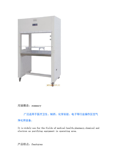
用途概念:summary广泛适用于医疗卫生、制药、化学实验、电子等行业操作区空气净化用设备。
It is widely use for the fields of medical health,pharmacy,chemical and electron as purifying equipment in operating area.产品特点:features采用不锈钢工作台面,耐腐,清洗方便。
Adopt the table surface of stainless steel,with corrosive resistace and being easy to wash,toughened glass side baffle,make a conmmodious and brightness working space.采用可调风量风机系统,轻触式开关调节电压,保证工作区风速始终处于理想状态。
Make use of adjustable fan unit system ,touching switchgear adjust voltage, keep the wind speed of working area always in perfect status.本产品由离心式风机和高效过滤器所组成的空气净化系统,洁净度高。
The product is of the air purifying system made of centrifugal fan and high effective filter,with clean height.垂直准闭合式台面,有效防止外部气流诱入和操作区异味对人体的刺激。
The vertical quasi-closed surface of table can prevent the airflow outside from inducing people and the peculiar smell in operative area from stimulating body effectively.技术参数:Specifications型号:单人水平、单人垂直、单人垂直双面、双人垂直、双人水平、双人垂直双面洁净等级:100级(美联邦209E)CLASS100(FED209E)菌落数:≤0.5个/皿*时(C90mm培养器皿)平均风速:0.3-0.6m/s (可调)噪音:≤62dB振动峰值::≤3um(X,Y,Z方向)照明度:≥300LX电源电压:AC,单相(single phase)220v/50hz输入功率:1500w高效过滤数量:820*600*120*1荧光灯/紫外灯规格及数量:20w1/20w*1工作区尺寸:860*480*570......1260*700*590超净工作台单人单面垂直4900 850×700×590单人双面垂直5000 850×700×590单人单面水平4920 860×480×570双人单面垂直9200 1260×650×590双人双面垂直9800 1260×650×590双人单面水平9800 1310×560×480单人单面垂直6500 850×700×590(推拉式移门)单人双面垂直6900 850×700×590 (推拉式移门)双人单面垂直10400 1260×650×590(推拉式移门)。

UV500检测器操作说明500检测器的使用和维护图2.1:检测器前面板16789111112534前面板见图2.1:以下控制和指示器位于前面板上:1)显示屏:A31/2数字显示器。
吸收值可显示到1.999AU。
当按下开关8(SAMP)时,这个显示屏显示样品相对光密度,当按下开关9(REF)时,这个显示屏显示参照光强度。
2)上升时间选择开关:一个四档旋转开关控制,能控制二级Beel滤器的过滤强度。
可选择的上升时间有0.1,0.3,1.0和3.0秒四档。
上升时间等于2倍的时间常数。
(以秒为单位)3)灵敏度选择开关:十二档的旋转开关控制仪器背板上的输出口的输出电压范围。
可供选择的有 2.0,1.0,0.5,0.2,0.1,0.05,0.02,0.01,0.005,0.002,0.001,和0.0005AUFS。
这个开关不控制仪器背板上的1V/AU积分仪输出端口的输出。
4)波长选择器:连续波长旋钮,可调范围190-800nm。
顺时针旋转降低波长,逆时针旋转增加波长。
箭头指示波长增加方向。
注意:不要强力旋转旋钮,使波长值低于180nm或高于820nm这会损坏波长控制器。
5)波长指示器:一个三位的机械波长指示器,显示当前工作波长。
6)紫外(UV)灯指示器:绿色发光二极管亮表示氘(D2)灯装于设备内并且发光。
7)可见光(VIS)灯指示器:绿色二极管灯亮表明这个设备内装着一个钨灯并且发光。
8)样品光强度开关:按下这个瞬间开关,显示器显示样品室光敏二极管测到的样品光密度。
9)参照光密度开关:也是瞬间开关,按下此开关,显示器显示参照光敏二极管测到的参照光密度。
10)短路开关:瞬时开关,按下这个按钮,记录仪输出端电压降为零伏。
这个按钮必须持续按压一会才能发挥作用。
这个按钮用于调整记录笔在记录纸上的位置,但不影响积分仪输出。
11)标记开关:瞬时开关按下该开关可产生偏转度达20%的输出信号,该开关不影响积分仪输出。
12)等待状态指示灯:绿色LED指示灯,此灯亮表示记录仪输岀端正在输出一个恒定的零电压。
烽火通信EPON AN5006-07设备介绍设备概述AN5006-07设备是烽火通信自主研发的目前业界领先的FTTB宽带接入设备,与烽火通信自主研发的EPON局端设备(OLT)一起,可以组成吉比特EPON系统,实现三网合一,可以满足高档写字楼或大型住宅的上网、电话及视频娱乐要求。
AN5006-07设备采用单板式(1U)结构,是一款高端口密度、高带宽、多业务的EPON远端设备,具有高可靠性、能提供服务质量(QoS)保证、可管理、可灵活扩容和组网的特点。
设备的各项功能和性能指标均满足ITU-T、IEEE相关建议和有关国际标准和行业标准的技术规范。
设备硬件结构AN5006-07设备根据传输距离、供电方式、是否提供语音业务、是否提供CA TV业务、是否提供光路保护功能等方面的不同,共分为32种不同型号的产品,用户可以根据需要选择最合适的产品。
AN5006-07产品型号说明:产品类型具体参见表1。
业务提供能力AN5006-07设备采用单纤波分复用方式,下行信号波长为1490nm,上行信号波长为1310nm,CA TV信号波长为1550nm。
仅需一根光纤就可以同时传输宽带数据业务、语音业务和CATV业务。
设备接口类型AN5006-07设备可提供以下接口:◆提供两个EPON接口(1+1保护),为EPON上联时的接口。
◆提供16个FE接口;◆提供16个话机接口(仅BXX型和CXX型产品提供);◆提供1个CATV接口(仅CXX型和DXX型产品提供)。
◆提供一个程序下载CONFIG口,用于程序下载。
◆提供一个CONSOLE口用于管理调试。
设备功能AN5006-07设备通过光纤经过ODN与OLT连接,可以和OLT组成光分路比为1:32的EPON系统网络,实现宽带数据业务、语音业务、CATV业务的接入。
语音业务在AN5006-07设备侧经过处理变成IP包,以IP包的形式在PON内传送,然后通过OLT的V5接口上联至PSTN,也可以通过OLT的千兆上联接口上联至软交换网络。
Installationsanleitung für das Powerline© 2012 NETGEAR, Inc. Alle Rechte vorbehalten.Kein Teil dieser Publikation darf ohne schriftliche Genehmigung von NETGEAR, Inc. in irgendeiner Form oder Weise reproduziert, übertragen, transkribiert, in einem Datenabfragesystem gespeichert oder in irgendeine Sprache übersetzt werden.Stapeln Sie elektronische Geräte NICHT, stellen Sie Geräte NICHT in engen Räumen auf, oder legen Sie sie NICHT in Schubladen. Stellen Sie sicher, dass das Gerät in einem freien Abstand von mindestens 5 Zentimetern aufgestellt ist.Technischer SupportDanke, dass Sie sich für NETGEAR entschieden haben. Unter können Sie Ihr Produkt registrieren, die neuesten Produkt-Updates beziehen oder den Online-Support in Anspruch nehmen.Telefon (nur USA und Kanada): 1-888-NETGEARTelefon (andere Länder):Siehe /app/answers/detail/a_id/984.MarkenNETGEAR, das NETGEAR-Logo und Connect with Innovation sind Marken und/oder eingetragene Marken von NETGEAR, Inc. und/oder seiner Tochtergesellschaften in den USA und/oder anderen Ländern. Informationen können ohne vorherige Ankündigung geändert werden. Andere Marken- und Produktnamen sind eingetragene Marken oder Marken der jeweiligen Inhaber. © 2011 NETGEAR, Inc. Alle Rechte vorbehalten. NutzungsbedingungenZur Verbesserung des internen Designs, des Betriebs und/oder der Zuverlässigkeit behält NETGEAR sich das Recht vor, die in diesem Dokument beschriebenen Produkte ohne vorherige Ankündigung zu ändern. NETGEAR lehnt im Zusammenhang mit dem Einsatz oder der Anwendung der hier beschriebenen Produkte oder Schaltpläne jegliche Haftung ab.Hardware-FunktionenPower-LEDPowerline-LEDNetzwerk-LEDSecurity-TasteReset-TasteNetzwerkanschlussBeschreibung der LEDsDie LEDs zeigen den Status der Powerline-Adapter an.• Wenn Sie den Adapter anschließen, leuchtet die Power LED auf und leuchtet grün.Der Adapter ist nicht aktiv, wenn seit mehr als 10 Minuten keine Netzwerkverbindung vorhanden ist. Der Adapter wechselt in den Energiesparmodus, und die Power-LED leuchtet gelb .• Die Powerline-LED leuchtet, wenn der Adapter mindestens ein anderes kompatibles Powerline-Gerät findet.Die Funktion Pick A Plug ermöglicht Ihnen die Auswahl desAnschlusses mit der besten Übertragungsrate, zu erkennen an der Farbe der Powerline-LED:- Grün: Übertragungsrate > 80 MBit/s (am besten)- Gelb: Übertragungsrate > 50 und < 80 MBit/s (besser)- Rot: Übertragungsrate < 50 MBit/s (gut)• Die Netzwerk-LED leuchtet, wenn Sie ein eingeschaltetes Netzwerkgerät mit mindestens einem Netzwerkanschlussverbinden.TastenbeschreibungenDie Tasten an Ihren Powerline-Adaptern haben die folgenden Funktionen:• Reset-Taste — Mit der Reset-Taste kann das Powerline-Gerät auf die werkseitigen Voreinstellungen zurückgesetzt werden.Halten Sie die Reset-Taste für eine Zeitspanne von 1 bis5 Sekunden lang gedrückt, und lassen Sie sie wieder los.• Security-Taste — Die Security-Taste dient zum Festlegen der Sicherheit zwischen den Powerline-Geräten. Halten Sie dieSecurity-Taste für eine Zeitspanne von 2 bis 5 Sekunden lang gedrückt, und lassen Sie sie wieder los.Weitere Informationen zu den Einstellungen für die Sicherheit finden Sie unter Installieren der Powerline-Adapter auf Seite 7.Installieren der Powerline-AdapterAdaptern.Schritt 1:Stecken Sie diezwei Powerline-eine Steckdose.Schritt 2:Drücken Sie aufSecurity-Tastebis 5 Sekundenlang, und lassenSie sie los. DiePowerline-LEDblinkt.Die Power-LEDleuchtet auf. Diestellungen istabgeschlossen.Hinzufügen eines neuen Powerline-Adapters zum sicherenTechnischer SupportVielen Dank, dass Sie sich für Produkte von NETGEAR entschieden haben.Nach der Installation des Geräts können Sie das Produkt mit der Seriennummer, die Sie auf dem Etikett Ihres Produkts finden, unter https:// registrieren.Die Registrierung ist Voraussetzung für die Nutzung des telefonischen Supports. Die Registrierung über die NETGEAR-Website wird dringend empfohlen.Produkt-Updates und Internetsupport finden Sie unter.Weitere Informationen zur Einrichtung, Konfiguration und Verwendung Ihres Powerline-Adapters finden Sie im Benutzerhandbuch.Kompatible NETGEAR Powerline-Geräte Ihr Powerline-Adapter kann ein Powerline-Netzwerk mit diesen kompatiblen NETGEAR-Geräten teilen: XAV101, XAV1004,XAV2001, XAV1101, XAV1301, XAV1401, XAV1601, XAV2101, XAV2501, XAV2602, XAV5001, XAV5501, XAV5601 und XAV5004. Eine vollständige Liste HomePlug-AV-zertifizierter Geräte finden Sie unter /certified_products.VorschrifteneinhaltungKonformitätserklärungenDie vollständige DoC finden Sie auf der NETGEAR-Website mit der EU-Konformitätserklärung unter: /app/answers/detail/a_id/11621/. Informationen über GNU General Public License (GPL) finden Sie unter/app/answers/detail/a_id/2649.WARNUNG: Stapeln Sie elektronische Geräte NICHT, stellen Sie sie NICHT in engenRäumen oder auf Teppichboden auf, und legen Sie sie NICHT in Schubladen. Stellen Sie sicher, dass das Gerät in einem freien Abstand von mindestens 5 Zentimetern aufgestellt ist.Dieses Symbol wurde in Übereinstimmung mit der EU-Richtlinie 2002/96/EGüber Elektro- und Elektronik-Altgeräte (WEEE-Richtlinie) hier angebracht. DieEntsorgung dieses Produkts innerhalb der Europäischen Union sollte inÜbereinstimmung mit den in Ihrem Land zur Implementierung der WEEE-Richtlinie geltenden Gesetzen gehandhabt werden.NETGEAR, das NETGEAR-Logo und Connect with Innovation sind Marken und/oder eingetragene Marken von NETGEAR, Inc. und/oder seiner Tochtergesellschaften in den USA und/oder anderen Ländern. Informationen können ohne vorherige Ankündigunggeändert werden. Andere Marken- und Produktnamen sind Marken oder eingetragene Marken der jeweiligen Inhaber. © 2012 NETGEAR, Inc. Alle Rechte vorbehalten.NETGEAR, Inc.350 East Plumeria Drive San Jose, CA 95134, USAJanuar 2012。
日本光荣厂是世界上三大出纳机具生产厂家之一,光荣牌清分机响负盛名,以速度快、准确度高、稳定性强著称。
UW-500/600 GLORY小型纸币清分机更高的工作效率与更低的初期投入成本根据“简单化”的理念改进后的新型设备GLORY为提供纸币处理效率而设计的新的解决方案为了减轻操作者的负担并进一步减少总的作业时间,GLORY在深入分析了现金处理的流程后,开发了业界顶尖的UW-500/600清分机。
他们具有一系列特性,例如:利用多出钞口系统提高清分与整理纸币的效率;采用双退钞口系统;使用大容量载钞架并加入压钞杆功能等。
UW-500/600性价比极高,价位适中。
作为GLORY为金融系统提供的最新解决方案,他们能使大规模现金处理流程变的更加稳定、高效、连续。
UW-500/600将为会帮助您在大幅度提高工作效率的同时消减成本。
为全面提供纸币处理效率而设计的UW—500/600典型工作流程批量清点每个出钞口都可以设定为批次操作,每个批量值多为500张。
不同面额的纸币经过清分进入对应的出钞口。
因为无需人工参与,纸币处理的速度更快,所需要的时间更短。
UW系列机器的新旧清分功能非常出色,能帮你及时回收破损券,并且避免A TM机发生故障。
与手工清分相比,UW系列机器在新旧清分时更为准确而高速不同面额的纸币经过清分后,能够进一步按照相同的方向与朝向排列。
为全面提供纸币处理效率而设计的UW—500/600功能特点更强的纸币识别技术异常出色的鉴伪表现纸币处理设备必须兼具高效、高速和精确的特性。
GLORY的清分机不仅对纸币进行新旧清分时效率高,而且鉴别伪钞的能力强,速度也快,每分钟最低可以处理多达720张以上的纸币,平均清发速度超过800张/分钟。
UW-500/600清分机除采用UV及红外光学、厚度、尺寸外,为中国市场成功研制出五磁头磁性辩伪检测传感器,使辩伪能力大大增强;同时增加了升级弹性,能很快适应新币种扩充
及能防伪的更新要求。
为了适应多种清分模式而设计的多出钞口系统重复清分的步骤更少UW-500拥有4个出钞口,UW-600拥有8个出钞口。
这样的设计将使您在处理不同的纸币时,能够自由组合多种清分方式,从而减少重复的清分步骤。
而这样的重复对于只有较少出钞口的清分机是必须的。
多达500张的大容量出钞口连续处理大量纸币时更为高效UW-500/600的每个出钞口都能容纳500张纸币,所以不用担心出钞口很快被放满。
连续处理大量纸币时再也无需频繁取出清分出的纸币,从而就提高了工作效率。
使用大容量的载钞架并加入压钞杆功能放置纸币所需的操作时间更少载钞架容量大,可以盛放1000张纸币。
在自动压钞杆的复制小,载钞架就可以确保每次只送入1张纸币,避免因为重张造成的卡钞和误点。
连续处理大量纸币时,还可以在纸币的堆放高度下降后,抬起压钞杆以便加入更多的纸币,使得工作更为连接。
双退钞口系统减少区分退钞时的工作双退钞口(150张x 2)可以盛放的退钞数量是通常设备的2倍。
可疑钞和其他原因的退钞可以被退到不同的退钞口。
这样就减少了区分不同种类退钞时所需要做的工作。
双LCD屏显示,指示更明确。
使用和操作更简单显示模块采用了两个并行的LCD屏幕:一个显示数据与信息,另一个则显示图形化的系统指示。
大型化的屏幕极大地提高了可视化程度维护更方便故障快速诊断恢复系统保证工作的连续性,设备的一大特点是上盖可以完全打开,维护纸币搬送部的工作因而变得更方便。
在点算和搬送过程中发生卡钞故障时,只要把设备主体的上半部分完全打开,就可以轻松地找到并移走卡住的纸币。
另外,积灰盘的采用还使得除尘工作变得简单。
4、友好人体工程学设计使工作更加舒心UW-500/600清分机的设计是配合于台面操作的,退钞架及送钞装置放得非常接近以减少操作人员走动的时间消耗,其工作高度以人体工程学考虑,75分贝的噪音使工作环境变得非常宁静,这些优点能减轻操作员在清分工作心理上的紧张和压力。