(02) IO and Drivers
- 格式:ppt
- 大小:2.23 MB
- 文档页数:57

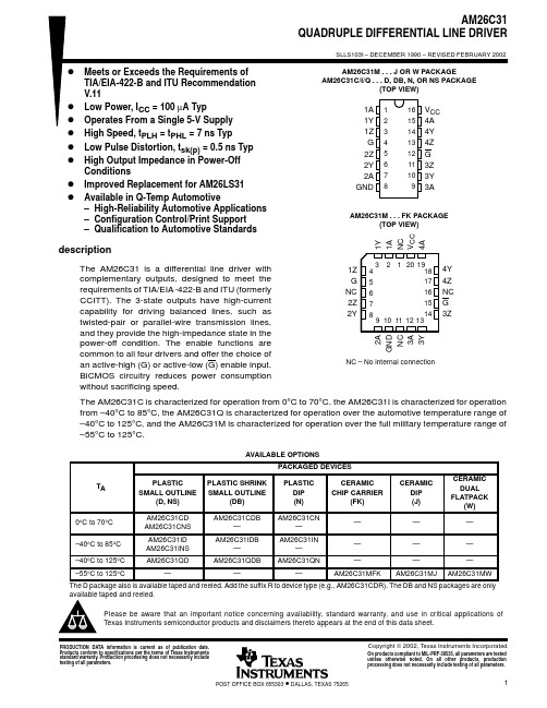
IMPORTANT NOTICETexas Instruments Incorporated and its subsidiaries (TI) reserve the right to make corrections, modifications, enhancements, improvements, and other changes to its products and services at any time and to discontinue any product or service without notice. Customers should obtain the latest relevant information before placing orders and should verify that such information is current and complete. All products are sold subject to TI’s terms and conditions of sale supplied at the time of order acknowledgment.TI warrants performance of its hardware products to the specifications applicable at the time of sale in accordance with TI’s standard warranty. Testing and other quality control techniques are used to the extent TI deems necessary to support this warranty. Except where mandated by government requirements, testing of all parameters of each product is not necessarily performed.TI assumes no liability for applications assistance or customer product design. Customers are responsible for their products and applications using TI components. To minimize the risks associated with customer products and applications, customers should provide adequate design and operating safeguards.TI does not warrant or represent that any license, either express or implied, is granted under any TI patent right, copyright, mask work right, or other TI intellectual property right relating to any combination, machine, or process in which TI products or services are used. Information published by TI regarding third–party products or services does not constitute a license from TI to use such products or services or a warranty or endorsement thereof. Use of such information may require a license from a third party under the patents or other intellectual property of the third party, or a license from TI under the patents or other intellectual property of TI.Reproduction of information in TI data books or data sheets is permissible only if reproduction is without alteration and is accompanied by all associated warranties, conditions, limitations, and notices. Reproduction of this information with alteration is an unfair and deceptive business practice. TI is not responsible or liable for such altered documentation.Resale of TI products or services with statements different from or beyond the parameters stated by TI for that product or service voids all express and any implied warranties for the associated TI product or service and is an unfair and deceptive business practice. TI is not responsible or liable for any such statements.Mailing Address:Texas InstrumentsPost Office Box 655303Dallas, Texas 75265Copyright 2002, Texas Instruments Incorporated。
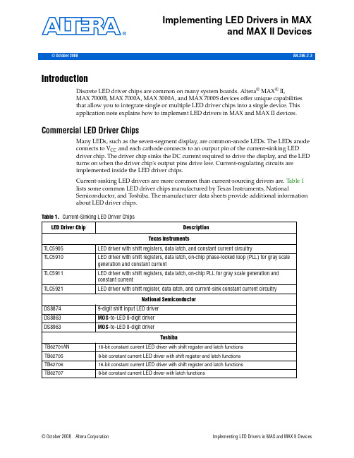
© October 2008Altera Corporation Implementing LED Drivers in MAX and MAX II DevicesAN-286-2.3© October 2008Implementing LED Drivers in MAXand MAX II DevicesIntroductionDiscrete LED driver chips are common on many system boards. Altera ®MAX ®II,MAX 7000B, MAX 7000A, MAX 3000A, and MAX 7000S devices offer unique capabilities that allow you to integrate single or multiple LED driver chips into a single device. This application note explains how to implement LED drivers in MAX and MAX II devices.Commercial LED Driver ChipsMany LEDs, such as the seven-segment display, are common-anode LEDs. The LEDs anode connects to V CC and each cathode connects to an output pin of the current-sinking LED driver chip. The driver chip sinks the DC current required to drive the display, and the LED turns on when the driver chip's output pins drive low. Current-regulating circuits are implemented inside the LED driver chips.Current-sinking LED drivers are more common than current-sourcing drivers are. Table 1 lists some common LED driver chips manufactured by Texas Instruments, NationalSemiconductor, and Toshiba. The manufacturer data sheets provide additional information about LED driver chips.Table 1.Current-Sinking LED Driver ChipsPage2Implementing LED Drivers in MAX and MAX II DevicesImplementing LED Drivers in MAX and MAX II DevicesWhen using a MAX or MAX II device as an LED driver chip, place a current-limitingresistor between the cathode side of the LEDs diode and the MAX or MAX II deviceI/O. The LEDs anode is tied to V CC, and is turned on when the MAX or MAX IIdevice I/O drive low.The most important aspect of an LED driver chip is the amount of current it has tosink. Many LED applications call for a current sink specification of 5 to 15mA.Because MAX II, MAX7000B, MAX7000A, MAX3000A, and MAX7000S devices cansink up to 50mA per pin, these MAX and MAX II device families can directlyintegrate commercial current-sinking LED driver chips.Table2 shows the maximum sink current per pin for MAX and MAX II devices.Table2.Maximum Sink Current for MAX and MAX II DevicesNote to Table2:(1)25mA is the absolute maximum rating for the sink current per pin in the MAX II device. Device operation at the absolute maximum ratings forextended periods of time may have adverse affects on the device. For the absolute maximum ratings of the MAX II device family, refer to the DC and Switching Characteristics chapter of the MAX II Handbook .Although a single pin from a MAX7000B device can sink up to 50mA of DC current,each GNDIO group can concurrently sink up to 200mA of current due to the supportof advanced I/O standards.Table3 shows the maximum source current for a set of I/O pins between any twoVCCIO pads or maximum sink current between any two GNDIO pads (regardless ofthe I/O bank) in MAX and MAX II devices.Table3.Maximum Source Current for Each VCCIO Group and Maximum Sink Current for Each GNDIO Group in MAX and MAX II DevicesFor example, the EPM240 device has six GNDIO pads, which provide six I/O regionsthat can sink up to 130mΑ. If you need to sink 15mA for the outputs, you can haveeight outputs per region. With the six regions of I/O between GNDIO pads, there are48 possible outputs, each sinking 15mA.Implementing LED Drivers in MAX and MAX II Devices© October 2008Altera Corporationf For more information about GNDIO grouping, refer to the MAX II Device Pin-OutFiles, and the MAX 7000B Device Pin-Out Files. These files are on the Pin-Outs page ofthe Literature section of the Altera website ().Implementing LED Driver ChipsFigure1 shows an example of an application circuit with the Toshiba TB62701ANLED, its 16-bit constant current LED driver with shift registers and latch functions.The 16 outputs of the circuit sink current for two seven-segment displays. You canimplement the LED driver chip in the circuitry using only one MAX or MAX II device,provided the device has enough register and pin capabilities to replace thefunctionality of the entire LED driver chip.Figure1.Application Circuit Example Using the Toshiba TB62701AN LED Driver ChipFigure2 shows a block diagram of the Toshiba TB62701AN LED driver chip. TheAltera LED driver reference design has the same architecture as the TB62701AN. Itconsists of three main categories:■16-bit serial shift registers■16-bit latches■An array of AND gatesThe data from serial-in that determines which LED to be driven is shifted serially intothe 16-bit shift registers for every low-to-high transition on the clock signal. With ahigh-to-low transition on the latch signal, the 16-bit data, which stores the 16-bit shiftregisters, is latched into 16-bit latches to drive the LED when the enable signals drivelow.© October 2008Altera Corporation Implementing LED Drivers in MAX and MAX II DevicesFigure2.Block Diagram of the Toshiba TB62701AN LED Driver ChipThe Altera LED driver reference design only emulates the functioning of the ToshibaTB62701AN. To implement the external resistor (R-EXT) and the current-regulatingcircuit, place an individual current-limiting resistor between the cathode side of theLEDs diodes and the I/O pins of the MAX or MAX II device.Figure3 shows the implementation of the LED driver using a MAX or MAX II device. Figure3.Implementing the LED Driver Using a MAX or MAX II DeviceImplementing LED Drivers in MAX and MAX II Devices© October 2008Altera CorporationThe right hand side of Figure3 shows the connection between discrete LEDs and theI/O pins of a MAX or MAX II device, while the left hand side shows the connectionbetween a seven-segment LED and the MAX or MAX II device. The output pins of theMAX or MAX II device connected to the LEDs are driven low to turn on the LEDs.1To download the LED drivers reference design, refer to the design files listed with AN286:Implementing LED Drivers in MAX and MAX II Devices, on the Literaturesection of the Altera web site ().Design ImplementationYou can target the LED drivers reference design in MAX II (EPM240T100C3) orMAX3000A (EPM3064ATC44) devices using the Quartus®II software. The designutilization in MAX II and MAX3000A devices is shown in Table4 and Table5.Table4.EPM240 LED Drivers Design UtilizationTable5.EPM3064A LED Drivers Design UtilizationDesign VerificationYou can achieve design verification for the LED driver by using the Quartus IIsoftware. MAX II and MAX3000A design verification occurs in both functional andtiming simulations. Figure4 shows the timing simulation of the LED drivers.© October 2008Altera Corporation Implementing LED Drivers in MAX and MAX II DevicesPage 6AdvantagesImplementing LED Drivers in MAX and MAX II Devices © October 2008Altera CorporationAs shown in Figure 4, the LED driver is first configured so that the parallel_out drives an output value of 1010101010101010. In the final configuration, the parallel_out output value is 1111111100000000.AdvantagesThe major advantage of implementing LED drivers with MAX or MAX II devices is that MAX or MAX II devices can also integrate other user logic using theirprogrammable logic. If you have to implement user logic on the same board as the LED driver, additional devices are required if you use a commercial LED driver chip. However, if a MAX or MAX II device is used, additional chips would not be required, saving valuable board space and reducing the overall system cost.ConclusionAltera’s MAX and MAX II devices not only provide solutions to the communications and industrial fields, but also offer simple solutions to integrate commodity products such as LED drivers. MAX and MAX II devices can integrate LED drivers and provide user logic, which saves on board space and reduces overall system cost.Referenced DocumentThis application note references the following documents:■DC and Switching Characteristics chapter of the MAX II Handbook■MAX II Device Pin-Out Files on the Pin-Outs page of the Literature section of the Altera website ( )■MAX 7000B Device Pin-Out Files on the Pin-Outs page of the Literature section of the Altera website ( ).Figure 4.LED Driver Timing Simulation in the Quartus II SoftwareNotes to Figure 4:(1)The high-to-low transition of the latch signal latches the serially-shifted input to drive the LED.(2)The low signal enables output to drive the LED.101 Innovation Drive San Jose, CA 95134Revision HistoryRevision HistoryTable 6shows the revision history for this FrameMaker template.Table 6.Template Revision History。
Fast I/O1996-1997 OSR Open Systems Resources, Inc.This article has been updated since its original date of publication.The standard dogma for Windows NT kernel mode development is that NT uses the I/O Request Packet (IRP) as the basis of communications with drivers – the advantage of the I/O Request packet is that it encapsulates the context needed for a particular operation and allows abstraction of the driver away from many of the details common to drivers.While this approach is very general and extensible – allowing for the cleanly layered Windows NT device architecture, there is a fair amount of overhead involved for operations where the request can be satisfied quickly. In that instance, the overhead associated with creating an IRP can dominate the cost of the entire operation – slowing the system down in performance critical areas. Because of this, the NT team introduced the concept of fast I/O. This approach to I/O is used by some file system drivers, such as NTFS, HPFS, FAT, and CDFS as well as the AFD transport driver which is used by WinSock.Any driver can register a set of fast I/O entry points but their use is often extremely limited – requiring that just the right conditions be met before a particular fast I/O entry point will even be called. For example, both the read and write fast I/O entry points are only called when information about the particular file is being maintained by the cache manager in Windows NT. We will describe these restrictions later in this article.Of course the most frustrating aspect of fast I/O for Windows NT is the total lack of available documentation – even the file system development kit does not provide a description of how fast I/O works or how to use it. In this article we will provide the rationale for fast I/O, a brief description of the various fast I/O calls, and conclude with some suggestions on how to use this interface to improve performance for your project.RationaleThe rationale for providing Fast I/O seems to be one of convenience – many I/O operations are repeatedly performed against the same data. For example, like most modern operating systems, Windows NT integrates file system caching with the virtual memory system – using the system memory as a giant cache for file system information. Such systems are extremely efficient and boost both the actual and perceived performance of the system.A second reason for this integration is Windows NT’s support for memory-mapped files. Supporting both read/write access and memory mapped file access to the same data, requires either a high cost (and hence low performance) cache consistency scheme or the scheme used by NT – where all data is stored in the virtual memory system. This ensures that data is always consistent – even between two programs accessing the same data using different access techniques.This tight integration means that both read and write operations can often be satisfied from this cached data. In the search for performance, then, this fact can be exploited for read and write by simply calling a specialized routine which moves data from the VM cache into the user’s memory, or vice versa. This eliminates the need to allocate an I/O request packet since the operation can be satisfied synchronously and need not call into lower drivers. It is this fundamental model which is realized by the fast I/O operations.Once these fast I/O entry points have been created to provide added performance for read and write, it is only a small additional step to adding other commonly performed operations to the list as well – and over time, this list has grown to its current (as of NT 3.51) list of thirteen entry points. As we describe each of these entry points, it will become obvious that most of them really are geared specifically towards supporting file systems and fast I/O. These entries are contained in the FAST_IO_DISPATCH structure as described in ntddk.h. The first element of this structure describes the size of the structure, providing a straight-forward mechanism for adding new elements to this data structure in the future in a compatible fashion.The I/O Manager and Fast I/OThe I/O Manager is responsible for calling the fast I/O entry points, as necessary. The model it uses is actually straight-forward for almost all the calls – the fast I/O entry points return either TRUE or FALSE indicating whether or not the fast I/O operation was completed. If it was not completed, or if fast I/O wasn’t available, an IRP is created and sent to the top level driver. The last three entry points in the FAST_IO_DISPATCH structure actually do not fit this model, however. Rather they provide slightly different services for the I/O manager. We will discuss them later in this article.FastIoCheckIfPossibleThe first call in the FAST_IO_DISPATCH structure is only used by file systems as part of the common file system runtime library (the FsRtl routines).. The prototype for this routine is:typedef BOOLEAN (*PFAST_IO_CHECK_IF_POSSIBLE) (IN struct _FILE_OBJECT *FileObject,IN PLARGE_INTEGER FileOffset,IN ULONG Length,IN BOOLEAN Wait,IN ULONG LockKey,IN BOOLEAN CheckForReadOperation,OUT PIO_STATUS_BLOCK IoStatus,IN struct _DEVICE_OBJECT *DeviceObject);This routine is only used for read and write operations. As such, it is called by the generic fast I/O routines provided in the FsRtl library to allow the specific file system to ascertain if a read or write (depending upon the value of the Boolean CheckForReadOperation parameter) can be satisfied from the file cache, while using a generic implementation of managing the file system cache. Note that the parameters to this call are extremely similar to those for the read and write fast I/O entry points – except that this routine does not have any data buffer associated with it.FastIoRead and FastIoWriteThis routine is called by the I/O manager whenever a read request is made for a file which has valid cached data associated with it. The prototype for this routine is:typedef BOOLEAN (*PFAST_IO_READ) (IN struct _FILE_OBJECT *FileObject,IN PLARGE_INTEGER FileOffset,IN ULONG Length,IN BOOLEAN Wait,IN ULONG LockKey,OUT PVOID Buffer,OUT PIO_STATUS_BLOCK IoStatus,IN struct _DEVICE_OBJECT *DeviceObject);As we noted previously, the basic parameters to this call are extremely similar to those used by FastIoCheckIfPossible, with this call having the necessary data buffer. All of these entry points are guaranteed that the passed in parameters have been validated so that, for instance, the buffer pointer is valid and available for reading in the calling thread’s context.The fast I/O routine can do one of two things: it can complete the operation, set the IoStatus field to indicate the result codes for the operation and return TRUE to the I/O manager. If that is the case, the I/O manager will complete the I/O operation. Alternatively, the routine can return FALSE, in which case the I/O manager will simply create an IRP and call the standard dispatch entry point.Note that returning TRUE doesn’t always guarantee the data has been transferred. For example, a read which starts past the end of file causes the IoStatus.Results field to be set to STATUS_END_OF_FILE, with no data copied. A read which crosses over the end of file will cause a TRUE to be returned, again with STATUS_END_OF_FILE set in the Results field, but this time with all remaining data in the file copied to the buffer.Similarly, returning FALSE doesn’t always guarantee that some data has not been transferred. While less likely, it is possible for some data to be successfully copied but then to experience an I/O error, or to have the memory of the buffer become inaccessible.In either case a number of secondary effects can occur. For example, while reading from the cache, it is possible that some of the data being read is not currently resident. This will result in a page fault which will result in a call back into the file system to satisfy the page fault.The only difference for the write case is that the Buffer argument is IN rather than OUT. The basic processing model is very similar. Of course, some error conditions are different – the media could be full, new pages may need to be allocated, etc.FastIoQueryBasicInfo and FastIoQueryStandardInfoThese operations provide support for the standard NtQueryInformationFile API operation, while FastIoQueryBasicInfo is also used for certain operations associated with NtCreateFile. The basic information includes information about when the file was created, when it was last accessed, when it was last modified, and any special attributes of the file – such as being a hidden file, a directory, or other appropriate attributes. The standard information includes information about the allocation size being used for the file, the current size of the file, the number of hard links to the file, an indication if deletion has been requested for the file, and an indicator if this particular file is a directory.Because this information is often cached in memory, it is a perfect candidate for fast I/O operations. Indeed, many standard utilities probe this information on a routine basis, which means that enhancing the performance of these operations will substantially increased the perceived performance of utilities, such as the File Manager (winfile.exe).The two fast I/O routines have the same interface:typedef BOOLEAN (*PFAST_IO_QUERY_BASIC_INFO) (IN struct _FILE_OBJECT *FileObject,IN BOOLEAN Wait,OUT PFILE_BASIC_INFORMATION Buffer,OUT PIO_STATUS_BLOCK IoStatus,IN struct _DEVICE_OBJECT *DeviceObject);The Wait parameter indicates if the caller is willing to block waiting for the requisite information. If this is set to FALSE then the call must either complete without waiting, or must return FALSE – in which case a normal IRP can be created, including the necessary context for the full operation. Interestingly enough, it appears that in NT 3.51 neither of these entry points are called with Wait set to FALSE. Of course, this might change in future versions of NT.Once invoked, these routines typically look at information they stored for the file when the FileObject was first opened. This information can also be reconstructed "on the fly" – for example, the last access time is set to the current system time by some file systems drivers. Of course, setting these values is determined by the file system implementation.FastIoLock, FastIoUnlockSingle, FastIoUnlockAll, and FastIoUnlockAllByKeyThese entry points are used to control lock state associated with a particular file. The locking being controlled by these calls is byte range locking against a single file. Thus, more than one byte range of a file can be locked. While not required, standard NT file systems utilize the services of the file system runtime package (the FsRtl routines) which provides a common code base for verifying that a requested lock can be granted and storing information about the lock ranges presently held on the file. Lock state can be controlled via the NT API calls NtLockFile as well as NtUnlockFile.Locks in Windows NT are one of two types – either exclusive locks, meaning the locked byte range is locked for modification, or shared locks, meaning the locked byte range is locked for reads. Multiple shared locks can be granted against overlapping byte ranges, and each is then stored until it is later released. Various pieces of information are stored about each lock so it can be acquired for rapid access later.The interface for FastIoLock is:typedef BOOLEAN (*PFAST_IO_LOCK) (IN struct _FILE_OBJECT *FileObject,IN PLARGE_INTEGER FileOffset,IN PLARGE_INTEGER Length,PEPROCESS ProcessId,ULONG Key,BOOLEAN FailImmediately,BOOLEAN ExclusiveLock,OUT PIO_STATUS_BLOCK IoStatus,IN struct _DEVICE_OBJECT *DeviceObject);Thus, the FileOffest and Length parameters correspond to the byte range being locked by the caller. The ProcessId provides information to identify the process which took out the lock – allowing cleanup later, for instance, when that process exits. The Key parameter provides an opaque value which can be used to associate multiple locks together for rapid access via the FastIoUnlockAllByKey call, for example. FailImmediately indicates if the call should block until the lock is available, or should immediately return failure. For the FsRtl routine, FailImmediately is ignored – if the lock is not available, FALSE is returned to the caller. The ExclusiveLock parameter indicates if this lock request is for exclusive (write) access or shared (read) access.The FastUnlockSingle routine is used to release the byte range locking on a portion of the file. The prototype for this call is:typedef BOOLEAN (*PFAST_IO_UNLOCK_SINGLE) (IN struct _FILE_OBJECT *FileObject,IN PLARGE_INTEGER FileOffset,IN PLARGE_INTEGER Length,PEPROCESS ProcessId,ULONG Key,OUT PIO_STATUS_BLOCK IoStatus,IN struct _DEVICE_OBJECT *DeviceObject);For most file systems, unless the file has associated Op Locks, this operation always returns TRUE, since even if the byte lock range is not accessible the operation has been completed (albeit with an error status). Since making the same call with an IRP would generate the same result, processing is completed at this stage.For this unlock operation to succeed, the FileOffset, Length, ProcessId, and Key must all match an existing byte range lock. Otherwise, the operation should complete with the error STATUS_RANGE_NOT_LOCKED set in the IoStatus block which will then be returned to the caller. The FastIoUnlockAll routine is used to release all byte range locks associated with a particular file being held by a particular process. The prototype for this function is:typedef BOOLEAN (*PFAST_IO_UNLOCK_ALL) (IN struct _FILE_OBJECT *FileObject,PEPROCESS ProcessId,OUT PIO_STATUS_BLOCK IoStatus,IN struct _DEVICE_OBJECT *DeviceObject);In this case, the fast I/O routine searches the available list of locks for the particular file and deletes any lock, whether exclusive or share, which is associated with the given ProcessId. This is used by the system when NtCloseFile is called, either because a program closed it or because a process was deleted.The FastIoUnlockAllByKey operation is used to delete a set of byte range locks which have been logically associated by the caller using a particular key value. The prototype for this routine is:typedef BOOLEAN (*PFAST_IO_UNLOCK_ALL_BY_KEY) (IN struct _FILE_OBJECT *FileObject,PVOID ProcessId,ULONG Key,OUT PIO_STATUS_BLOCK IoStatus,IN struct _DEVICE_OBJECT *DeviceObject);This call is provided for the benefit of file servers such as SRV. The I/O Manager in NT 3.51 does not appear to make any use of this call. This key allows a file server to associate a file lock with some remote client. Since it may represent many such remote clients, the use of the ProcessId alone is not sufficient. Similarly, since there are multiple file servers, the use of the Key alone might cause the erroneous release of file locks for some other file server. Combining the two ensures correct operation and allows for remote system locking.FastIoDeviceControlThis entry point is used for supporting the native NtDeviceIoControlFile call which is used essentially to implement private communications channels to kernel resident drivers. As with the other Fast I/O routines, this routine returns TRUE if the operation was completed, and FALSE otherwise. For the FALSE case, the I/O Manager creates an IRP and calls the dispatch entry point for the driver in question.The prototype for FastIoDeviceControl is:typedef BOOLEAN (*PFAST_IO_DEVICE_CONTROL) (IN struct _FILE_OBJECT *FileObject,IN BOOLEAN Wait,IN PVOID InputBuffer OPTIONAL,IN ULONG InputBufferLength,OUT PVOID OutputBuffer OPTIONAL,IN ULONG OutputBufferLength,IN ULONG IoControlCode,OUT PIO_STATUS_BLOCK IoStatus,IN struct _DEVICE_OBJECT *DeviceObject);Wait indicates if the caller is willing to wait for the operation to complete, although the Fast I/O routine may return FALSE even if Wait is set to TRUE. The InputBuffer points to an optional and potentially validated caller provided buffer which is considered "optional" from the perspective of this interface, although the implementation of the Fast I/O routine can return TRUE and indicate an error (e.g., STATUS_INV ALID_PARAMETER) if the InputBuffer is missing or of the wrong length. The OutputBuffer points to memory which maybe validated, depending upon the access type for the IoControlCode value. If IoControlCode indicates an access type of 3, the OutputBuffer is not validated and the Fast I/O routine is responsible for its validation. Otherwise, the buffer is validated prior to calling the Fast I/O routine. This approach is identical to that used for the normal IRP_MJ_DEVICE_CONTROL dispatch entry point.The implementation of this Fast I/O routine is dependent entirely upon the IoControlCode value passed to the FastIoDeviceControl routine. Typically, this entry point is associated with those kernel mode drivers which implement a rich private communications interface. Thus, none of the NT native file systems actually implement this entry point, but the WinSock support driver AFD uses this interface heavily for communications to the underlying transport drivers.Thus, the actual model for these communications is dependent entirely upon the driver implementation of the Fast I/Oroutines.AcquireFileForNtCreateSection and ReleaseFileForNtCreateSectionThese two routines do not fit the pattern established by the other entries in the Fast I/O dispatch table. Rather, they appear to have been used to resolve certain locking issues surrounding the HPFS file system (as of the four native NT file systems, only HPFS actually uses these entries). The prototype for these two calls is identical and quite simple:typedef VOID (*PFAST_IO_ACQUIRE_FILE) (IN struct _FILE_OBJECT *FileObject);The AcquireFileForNtCreateSection call is made prior to mapping in pages from a file stored within the file system to ensure that any driver-specific locking has been done. The ReleaseFileForNtCreateSection call is made to release the locks acquired earlier for the file mapping operation.As it turns out, if these entry points are not provided, the I/O Manager utilizes a default mechanism for ensuring proper synchronization for the file mapping operations.FastIoDetachDeviceThis last routine is a most curious one. The ntddk.h file does provide a hint as to the purpose of this call – namely, it is called when a device object is about to be deleted. We found this call is extremely useful when developing filter drivers for file systems, since the device objects of removable file systems are destroyed whenever the underlying media is changed. Sometimes this occurs immediately, but it can occur at almost any time after the media has been removed, depending upon what portions of the system are still caching information.The prototype of this call is:typedef VOID (*PFAST_IO_DETACH_DEVICE) (IN struct _DEVICE_OBJECT *SourceDevice,IN struct _DEVICE_OBJECT *TargetDevice);In our experience, a filter driver for removable media file systems must be able to handle this call as the system will halt otherwise.[Note that the fast I/O calls beyond this point were not described in the original article.]FastIoQueryNetworkOpenInfoA common operation for the LanManager (CIFS) file server is to open a file and retrieve both its standard and basic attributes. This information is then combined and sent to the remote client (the LanManager/CIFS redirector) so that it can be presented to the remote application programs.Prior to NT 4.0, SRV was required to pass an IRP to the underlying file system multiple times to extract the same information. Beginning with NT 4.0 a new information type, identified by the FileNetworkOpenInformation file information type, was added to the file systems interface so that a network file server, such as SRV, could extract this information in a single operation. To further speed this process, a corresponding fast I/O entry point was also added. The prototype for this is:typedef BOOLEAN (*PFAST_IO_QUERY_NETWORK_OPEN_INFO) (IN struct _FILE_OBJECT *FileObject,IN BOOLEAN Wait,OUT struct _FILE_NETWORK_OPEN_INFORMATION *Buffer,OUT struct _IO_STATUS_BLOCK *IoStatus,IN struct _DEVICE_OBJECT *DeviceObject);As with the other fast I/O routines, the FileObject represents the file on which the caller is acting. The Wait parameter indicates if the caller is willing to block. If Wait is FALSE this routine should not block. The caller can then use the standard IRP path to obtain this information from the file system. The Buffer argument points to the location where the data should be copied, and the IoStatus block points to the standard I/O status information. Finally, the DeviceObject represents the file system instance being queried.Since this is used by SRV, this is only implemented by physical file systems.FastIoAcquireForModWriteThis call was added to allow an alternate mechanism for locking the file prior to the Modified Page Writer in the memory manager actually performing I/O. This function is entirely optional - but if you do not implement it, the File System Runtime Library will us the ERESOURCE pointers in the common header of the file object to ensure correctsynchronization (so your file system must be using the standard NT locking model.)typedef NTSTATUS (*PFAST_IO_ACQUIRE_FOR_MOD_WRITE) (IN struct _FILE_OBJECT *FileObject,IN PLARGE_INTEGER EndingOffset,OUT struct _ERESOURCE **ResourceToRelease,IN struct _DEVICE_OBJECT *DeviceObject);The FileObject identifies the specific file to be locked, the EndingOffset indicates the highest byte in the file that the Modified Page Writer is going to write. You can use this information in your file system to synchronize anyone attempting to truncate the file during this operation. The ResourceToRelease is an optional parameter your FSD can return. If you return anything except a PERESOURCE you must also implement the complimentary entry point (FastIoReleaseForModWrite) which is described later in this article. The DeviceObject represents the file system instance.FastIoMdlReadThis call was added to allow optimal performance for SRV (or other kernel resident services.) Prior versions of Windows NT allowed SRV to retrieve MDLs into the cache directly, but only when using the IRP path. This new entry point now provides a direct function call method for SRV to achieve the same results.typedef BOOLEAN (*PFAST_IO_MDL_READ) (IN struct _FILE_OBJECT *FileObject,IN PLARGE_INTEGER FileOffset,IN ULONG Length,IN ULONG LockKey,OUT PMDL *MdlChain,OUT PIO_STATUS_BLOCK IoStatus,IN struct _DEVICE_OBJECT *DeviceObject);The FileObject uniquely identifies the file being read, while the FileOffset and Length arguments identify the region of the file being read. The LockKey is used to perform the correct mandatory byte range locking checks, as this read is an "application level" read. The MdlChain is one (or more) MDLs describing the cache buffer. The IoStatus block indicates the completion status of the read operation (since this may require the data be read from disk.) TheDeviceObject represents the file system instance.Typically, this is implemented by file systems either using support routines from the FsRtl package or by calling CcMdlRead direcly.FastIoMdlReadCompleteThis call is used by SRV (or other kernel-resident services) to release an MDL previously acquired via a call to FastIoMdlRead.typedef BOOLEAN (*PFAST_IO_MDL_READ_COMPLETE) (IN struct _FILE_OBJECT *FileObject,IN PMDL MdlChain,IN struct _DEVICE_OBJECT *DeviceObject);The FileObject identifies the file for which the MDL is being released. The MdlChain is the chain returned from a previous call to FastIoMdlRead. The DeviceObject represents the file system instance.Typically, this is implemented by file systems either using support routines from the FsRtl package or by calling CcMdlReadComplete.File System Filter Driver Writers beware! CcMdlReadComplete calls this entry point and ignores the return value (as of NT 4.0 SP3) which will cause memory loss when filtering any file system which uses CcMdlReadComplete (and both FAT and NTFS work in this fashion.)FastIoPrepareMdlWriteThis entry point is used by SRV (or other kernel-resident services) to obtain a pointer to a range of memory within the cache which can be written to directly. This avoids the "memory copy" limitations inherent in providing buffers (as application programs do.)typedef BOOLEAN (*PFAST_IO_PREPARE_MDL_WRITE) (IN struct _FILE_OBJECT *FileObject,IN PLARGE_INTEGER FileOffset,IN ULONG Length,IN ULONG LockKey,OUT PMDL *MdlChain,OUT PIO_STATUS_BLOCK IoStatus,IN struct _DEVICE_OBJECT *DeviceObject);The FileObject uniquely identifies the file being written, while the FileOffset and Length arguments identify the region of the file being written. The LockKey is used to perform the correct mandatory byte range locking checks, as this write is an "application level" write. The MdlChain is one (or more) MDLs describing the cache buffer. The IoStatus block indicates the completion status of the write operation (since this may require that some data be read from disk.) The DeviceObject represents the file system instance.Typically, this is implemented by file systems either using support routines from the FsRtl package or by calling CcMdlWrite direcly.FastIoMdlWriteCompleteThis call is used by SRV (or other kernel-resident services) to release an MDL previously acquired via a call to FastIoMdlRead.typedef BOOLEAN (*PFAST_IO_MDL_WRITE_COMPLETE) (IN struct _FILE_OBJECT *FileObject,IN PLARGE_INTEGER FileOffset,IN PMDL MdlChain,IN struct _DEVICE_OBJECT *DeviceObject);The FileObject identifies the file for which the MDL is being released. The MdlChain is the chain returned from a previous call to FastIoMdlRead. The DeviceObject represents the file system instance.Typically, this is implemented by file systems either using support routines from the FsRtl package or by calling CcMdlReadComplete.File System Filter Driver Writers beware! CcMdlWriteComplete calls this entry point and ignores the return value (as of NT 4.0 SP3) which will cause data and memory loss when filtering any file system which uses CcMdlReadComplete (and both FAT and NTFS work in this fashion at present.)FastIoReadCompressedThis call was added to allow SRV (or other kernel-resident services) to fetch data in compressed format from the underlying file system. This can only be used for files that are compressed using the standard Windows NT compression libraries (such as "LZW1".) This routine can be used to either copy the data to a buffer provided by the caller, or it can return the data in a fashion described as an MDL.typedef BOOLEAN (*PFAST_IO_READ_COMPRESSED) (IN struct _FILE_OBJECT *FileObject,IN PLARGE_INTEGER FileOffset,IN ULONG Length,IN ULONG LockKey,OUT PVOID Buffer,OUT PMDL *MdlChain,OUT PIO_STATUS_BLOCK IoStatus,OUT struct _COMPRESSED_DATA_INFO *CompressedDataInfo,IN ULONG CompressedDataInfoLength,IN struct _DEVICE_OBJECT *DeviceObject);The FileObject uniquely identifies the file being read, while the FileOffset and Length arguments identify the region of the file being read. The LockKey is used to perform the correct mandatory byte range locking checks, as this read is an "application level" read. The Buffer argument is an (optional) buffer into which the compressed data is to be copied. The MdlChain (also optional) is a pointer which will be set to point to one (or more) MDLs describing the cache buffer. The IoStatus block indicates the completion status of the read operation (since this may require the data be read from disk.) The CompressedDataInfo and CompressedDataInfoLength identify the buffer provided where the compression information for the block being read is copied. The DeviceObject represents the file system instance.FastIoWriteCompressedThis call was added to allow SRV (or other kernel-resident services) to store data in compressed format in the underlying file system. This can only be used for files that are compressed using the standard Windows NT compression libraries (such as "LZW1".)typedef BOOLEAN (*PFAST_IO_WRITE_COMPRESSED) (IN struct _FILE_OBJECT *FileObject,。

Agilent M9360A PXI Attenuator/Preselector100 kHz to 26.5 GHzData SheetChallenge the Boundaries of TestAgilent Modular ProductsOVERVIEWIntroductionWith attributes that provide enough performance to satisfy even the most demanding spectrum analysis applications, the Agilent M9360A PXI Attenuator/Preselector is a 3-slot, 3U, combination module providing attenuation and prese-lection signal conditioning for numerous system applica-tions with an electronically tuneable, 4-stage, YIG-tuned filter (YTF) based RF-input pre-selector, and broadband switches for signal distribution.Product DescriptionThe M9360A provides the necessary input signal condition-ing and routing for the Agilent M9351A and M9361A down-converters. It employs a 70 dB (10 dB/step) input step attenuator that enables a dynamic range of +30 dBm to–160 dBm, typical. The module uses broadband switches to distribute the incoming RF signal to other PXI modules for further processing with minimal signal degradation. In addition, the electronically tuneable YTF allows for greater than 80 dB input image rejection and greater than 40 MHz of instantaneous bandwidth. For additional bandwidth, the M9360A offers a bypass path that automatically routes signals around the band limited preselector. In additionto functioning as an analog front end for downconversion applications, the M9360A is also useful for providing RF and microwave attenuation or band-pass filtering.When integrated in the Agilent M9392A PXI Vector Signal Analyzer, and combined with the 89600 VSA software,the M9360A provides a complete signal analyzer solution enabling analysis of communications, radar and avionics signals to 26.5 GHz in a modular open-system standard.Applications• Aerospace and defense• Wireless communications• Radar and wideband signal captureFeatures• Frequency range: 100 kHz to 26.5 GHz• 35 MHz bandwidth (preselected, < 3 GHz)• 40 MHz bandwidth (preselected, ≥ 3 GHz)• Automatic signal routing for additional bandwidth with bypass path• 2.75 GHz to 26.5 GHz (YIG tuned filter path)• 70 dB step attenuator• Chassis slot compatibility: cPCI (J1), PXI-1, PXIe Hybrid • PXI form factorCustomer values• Multiple programmatic interfaces enable easy integra-tion into existing test environments and reduced development time• Analyze large bandwidth signals• Included drivers, soft front panels and programming examples in Visual Studio (, C#, C/C++), VEE, LabVIEW, LabWindows/CVI, and MATLAB•Conforms to Modular Open Systems Approach (MOSA)EASY SETUP ... TEST ... AND MAINTENANCEHardware platformComplianceThe M9360A is PXI compliant, using either a cPCI (J1), PXI-1, or PXIe Hybrid slot. Designed to benefit from fast data interfaces, the products can be integrated with other test and automation modules in cPCI(J1), PXI-1, or PXIe Hybrid chassis slots. The PXI format offers high perfor-mance in a small, rugged package. It is an ideal deploy-ment platform for many automated test systems.A wide array of complementary PXI products are currently available. Products include multimeters, waveform genera-tors, local oscillators, digitizers, and switch multiplexers.Software platformIO LibrariesAgilent IO Libraries Suite offers FAST and EASY connec-tion to instruments and the newest version extends that capability to include modular instruments.The Agilent IO Libraries Suite helps you display ALL of the modules in your system, whether they are PXI, PXIe, or PCIe. From here you can view information about the installed software or start the module’s soft front panel. Launch the module’s soft front panel directly from Agilent Connection Expert.Find the right driver from Agilent Connection Expert.DriversAgilent provides instrument drivers that work with your choice of software that saves time and preserves software and hardware investments. Agilent modular instruments come with IVI-COM, IVI-C, LabVIEW and MATLAB software drivers that work in the most popular T&M devel-opment environments including, Visual Studio(, C#, C/C++), VEE, LabVIEW, LabWindows/CVI, and MATLAB.With the multiple drivers included and minimum software adjustments, any Agilent PXI attenuator/preselector can be swapped out, replaced, or upgraded with the latest PXI attenuator/preselector.Easy software integrationIncluded are application code examples for Visual Studio (, C#, C/C++), VEE, LabVIEW, LabWindows/CVI, and MATLAB which provide attenuator/preselector set up and basic acquisition functionality. These application code examples are easily modified to quickly integrate the module into your measurement system.Software applicationsAgilent soft front panels provide easy to use instrument communications for diagnostics and basic hardware setup. The M9360A’s graphical user interface guides developers through module setup. Users can quickly configure the instrument parameters. More sophisticated functions are available through the instrument’s numerous program-matic interfaces. The M9360A supports interfaces for Visual Studio, MATLAB, and LabVIEW. The interfaces are implemented using the IVI standard supporting both IVI-COM and IVI-C.Calibration intervalsThe M9360A is factory calibrated and shipped with an ISO-9002, NIST-traceable calibration certificate. A one year calibration cycle is recommended.Figure 1. Agilent M9360A PXI Attenuator/Preselector, softwareinterfaceTemperature range Operating Non-operating 0 °C to 55 °C –40 °C to +70 °C ConnectorsRF IN RF 1 OUT RF 2 OUT LO IN LO 1 OUT LO 2 OUTAPC 3.5 (precision type) SMA (f)SMA (f)SMA (f)SMA (f)SMA (f)EMCComplies with European EMC Directive 2004/108/EC • IEC/EN 61326-2-1• CISPR Pub 11 Group 1, class A • AS/NZS CISPR 11• ICES/NMB-001This ISM device complies with Canadian ICES-001.Cet appareil ISM est conforme a la norme NMB-001 du Canada.Warm-up time15 minutes, minimum1Attenuator set to 10 dB.TECHNICAL SPECIFICATIONS AND CHARACTERISTICSTECHNICAL SPECIFICATIONS AND CHARACTERISTICS, CONTINUEDPower dissipation+3.3 V +5 V+12 V–12 V Total power0.1 A0.6 A 1.3 A0.1 A21 W maxDimensions • 3U/3-slot PXI/CompactPCI standard• Chassis slot compatibility: cPCI (J1), PXI-1, PXIe Hybrid• Front panel complies with IEEE1101.10 certification andcomplianceWeight 3.5 lb/1.6 kgTopic Windows7 and Vista Requirements Windows XP RequirementsOperating systems Windows 7(32-bit and 64-bit)Windows Vista, SP1 and SP2 (32-bit and64-bit)Windows XP, Service Pack 3Processor speed 1 GHz 32-bit (x86), 1 GHz 64-bit (x64)(no support for Itanium 64)600 MHz or higher required 800 MHz recommendedAvailable memory 4 GB minimum8 GB or greater recommended3 GB minimumAvailable disk space 11.5 GB available hard disk space, includes:• 1 GB available for Microsoft .NETFramework 3.5 SP1 2• 100 MB for Agilent IO Libraries Suite1.5 GB available hard disk space,includes:• 1 GB available for Microsoft .NETFramework 3.5 SP1 2• 100 MB for Agilent IO Libraries SuiteVideo Support for DirectX 9 graphics with128 MB graphics memory recommended(Super VGA graphics is supported)Super VGA (800 x 600) 256 colors or moreBrowser Microsoft Internet Explorer 7.0 or greater Microsoft Internet Explorer 6.0 or greater 1Because of the installation procedure, less memory may be required for operation than is required for installation. Framework Runtime Components are installed by default with Windows Vista and Windows 7. Therefore, you may not need this amount of available disk space.Related productsM9202A PXIe IF Digitizer: 12-bit, 2 GS/s M9302A PXI Local Oscillator: 3 GHz to 10 GHz M9361A PXI Downconverter: 2.75 MHz to 26.5 GHz M9351APXI Downconverter: 50 MHz to 2.9 GHz M9392A PXI Vector Signal Analyzer: 50 MHz to 26.5 GHz M9018A PXIe 18-slot Chassis M9036APXIe Embedded Controller 2AccessoriesSoftware, example programs, and product information on CD (included)Cables (included)CONFIGURATION AND ORDERING INFORMATIONFigure 2. Simplifed block diagram of the M9360A PXI Attenuator/Preselector.Ordering 11M9360A PXI Attenuator/Preselector: 100 kHz to 26.5 GHzIncludesSoftware and product information on CD and cablesSoftwareSupported operating systems Microsoft Windows XP (32-bit),Microsoft Windows Vista (32/64-bit), Microsoft Windows 7 (32/64-bit)Standard compliant drivers IVI-COM, IVI-C, LabVIEW, MATLABSupported application development environments (ADE)Visual Studio (, C#, C/C++), VEE, LabVIEW, LabWindows/CVI, MATLABAgilent IO LibrariesIncludes: VISA Libraries, Agilent Connection Expert, IO MonitorM9360A PXI Attenuator/Preselector1For the M9360A to work properly, at least one PXI chassis and one PXI controller type must be available.2PC desktop and PC laptop controllers are also available. Please see the M9392A Configuration Guide (literature no. 5990-8254EN) for more information.R-51B-001-3X Express warranty – 3 years 1R-51B-001-5XExpress warranty – 5 years 11Options not available in all countries.Express WarrantyReduce downtime with the fastest repair service in the industry. The express warranty upgrades the global warranty to provide:• 5 day typical turnaround repair service in the US, Japan, China and many EU countries or up to a 10 day improve ment in turnaround time in the rest of the world.• Priority return shipmentWARRANTY AND CALIBRATIONDefinitions for specificationsSpecifications describe the warranted performance of calibrated instruments that have been stored for a minimum of 2 hours within the operating temperature range of 0 °C to 55 °C, unless otherwise stated, and after a 45 minute warm-up period. Data represented in this document are specifications unless otherwise noted.Characteristics describe product performance that is useful in the application of the product, but that is not covered by the product warranty. Characteristics are often referred to as Typical or Nominal values.• Typical describes characteristic performance, which 80% of instruments will meet when operated over a 20 °C to 30 °C temperature range. Typical performance is not warranted.• Nominal describes representative performance that is useful in the application of the product when operated over a 20 °C to 30 °C temperature range. Nominal performance is not warranted.Note: All graphs contain measured data from several units at room temperature unless otherwise noted.The modular tangramThe four-sided geometric symbol that appears in thisdocument is called a tangram. The goal of this seven-piece puzzle is to create identifiable shapes—from simple to complex. As with a tangram, the possibilities may seem infinite as you begin to create a new test system. With a set of clearly defined elements—hardware, software—Agilent can help you create the system you need, from simple to complex.PICMG and the PICMG logo, CompactPCI and the CompactPCI logo, AdvancedTCA and the AdvancedTCA logo are US registered trademarks of the PCI Industrial Computers Manufacturers Group. “PCIe” and “PCI EXPRESS” are registered trademarks and/or service marks of PCI-SIG.Challenge the Boundaries of TestAgilent Modular Products/quality Agilent SolutionPartners /find/solutionpartners/find/modular /find/m9360aFor more information on Agilent Technologies’ products, applications or services, please contact your local Agilent office. The complete list is available at: /find/contactus Americas Canada Brazil MexicoUnited States (877) 894 4414 (11) 4197 360001800 5064 800 (800) 829 4444Asia Pacific Australia ChinaHong Kong India Japan Korea Malaysia Singapore TaiwanOther AP Countries 1 800 629 485800 810 0189800 938 6931 800 112 9290120 (421) 345080 769 08001 800 888 848180****81000800 047 866(65) 375 8100Europe & Middle East Belgium Denmark Finland France Germany Ireland Israel ItalyNetherlands Spain SwedenUnited Kingdom32 (0) 2 404 93 40 45 45 80 12 15358 (0) 10 855 21000825 010 700**0.125 €/minute 49 (0) 7031 464 6333 1890 924 204972-3-9288-504/54439 02 92 60 848431 (0) 20 547 211134 (91) 631 33000200-88 22 5544 (0) 118 927 6201For other unlisted countries: /find/contactus (BP-10-02-13)Product specifications and descriptions in this document subject to change without notice.© Agilent Technologies, Inc. 2010 – 2013Published in USA, December 9, 20135990-6057EN。
Plug N Drive TM Integrated Power Module for Appliance Motor DriveFeatures• Integrated Gate Drivers and Bootstrap Diodes.• Temperature Monitor• Temperature and Overcurrent shutdown • Fully Isolated Package.• Low VCE (on) Non Punch Through IGBT Technology• Under-voltage lockout for all channels• Matched propagation delay for all channels • Low side IGBT emitter pins for current conrol • Schmitt-triggered input logic• Cross-conduction prevention logic• Lower di/dt gate driver for better noise immunityDescriptionInternational Rectifier's IRAMS10UP60A is an Integrated Power Module developed and optimized for elec-tronic motor control in appliance applications such as washing machines and refrigerators. Plug N Drive technology offers an extremely compact, high performance AC motor-driver in a single isolated package for a very simple design.A built-in temperature monitor and over-temperature/over-current protection, along with the short-circuit rated IGBTs and integrated under-voltage lockout function, deliver high level of protection and fail-safe operation.The integration of the bootstrap diodes for the high-side driver section, and the single polarity power supply required to drive the internal circuitry, simplify the utilization of the module and deliver further cost reduction advantages.Absolute Maximum RatingsPD-94640 RevIIRAMS10UP60ASeries10A, 600VParameter DescriptionMax. ValueUnits V CES Maximum IGBT Blocking Voltage 600V +Positive Bus Input Voltage 450I O @ T C = 25°C RMS Phase Current 10I O @T C =100°C RMS Phase Current5I pk Maximum Peak Phase Current (tp<100ms)15F p Maximum PWM Carrier Frequency 20kHz P d Maximum Power dissipation per Phase 20W V isoIsolation Voltage (1min)2000V RMS T J (IGBT & Diodes)Operating Junction temperature Range -40 to +150T J (Driver IC)Operating Junction temperature Range -40 to +150TMounting torque Range (M3 screw)0.8 to 1.0NmVA °C • Recognized by UL (E252584), RoHS CompliantIRAMS10UP60AIRAMS10UP60AThermal ResistanceInverter Section Electrical Characteristics @ T J = 25°CInverter Section Switching CharacteristicsSymbol ParameterMin Typ Max Units E on Turn-On Switching Loss ---200235E off Turn-Off Switching Loss ---75100E tot Total Switching Loss ---275335T J =25°C E on Turn-on Swtiching Loss ---300360T J =150°CE off Turn-off Switching Loss ---135165E tot Total Switching Loss ---435525Erec Diode Reverse Recovery energy---3040µJt rr Diode Reverse Recovery time ---100145nsRBSOAReverse Bias Safe Operating AreaSCSOA Short Circuit Safe Operating Area10------µsFULL SQUARET J =150°C, I C =5A, V P =600V V +=480V, V DD =+15V to 0VSee CT3ConditionsI C =5A, V +=400V V DD =15V, L=1mH See CT1Energy losses include "tail" and diode reverse recoveryT J =150°C, V P =600V,V +=360V,V DD =+15V to 0V See CT2µJµJ T J =150°C, V + =400V V DD =15V, I F =5A, L=1mHSymbol ParameterMin Typ Max Units Conditions R th(J-C)Junction to case thermal resistance, each IGBT under inverter operation.--- 4.24.7°C/WR th(J-C)Junction to case thermalresistance, each Diode under inverter operation.--- 5.5 6.5°C/W R th(C-S)Thermal Resistance case to sink---0.1---°C/WFlat, greased surface. Heatsink compound thermalconductivity - 1W/mK Symbol ParameterMin Typ Max Units Conditions V (BR)CESCollector-to-Emitter Breakdown Voltage600------V V IN =0V, I C =20µA ∆V (BR)CES / ∆T Temperature Coeff. Of Breakdown Voltage---0.57---V/°C V IN =0V, I C =1.0m A (25°C - 150°C)--- 1.7 2.0I C =5A T J =25°C, V DD =15V --- 2.0 2.4I C =5A T J =150°C ---515V IN =5V, V +=600V---1040V IN =5V, V +=600V, T J =150°C I lk_module Zero Gate Phase-to-Phase Current----50µAV IN =5V, V +=600V --- 1.8 2.35I C =5A--- 1.31.7I C =5A, T J =150°CVµA VV CE(ON)I CES V FMCollector-to-Emitter Saturation VoltageZero Gate Voltage Collector Current-to-Emitter Diode Forward Voltage DropIRAMS10UP60ARecommended Operating Conditions Driver FunctionThe Input/Output logic timing diagram is shown in Figure 1. For proper operation the device should be used within the recommended conditions. All voltages are absolute referenced to V SS . The V S offset is tested with all supplies biased at 15V differential (Note 1). All input pin (V IN ) and I TRIP are clamped with a 5.2V zener diode and pull-up resistor to V DDSymbol Definition Min Max Units V B1,2,3High side floating supply voltage V S +12V S +20V S1,2,3High side floating supply offset voltage Note 2450V DD Low side and logic fixed supply voltage 1220V ITRIP T/I TRIP input voltage V SS V SS +5V INLogic input voltage LIN, HINV SSV SS +5VV V Static Electrical Characteristics Driver FunctionV BIAS (V CC , V BS1,2,3)=15V, unless otherwise specified. The V IN and I IN parameters are referenced to V SS and are appli-cable to all six channels. (Note 1)Absolute Maximum Ratings Driver FunctionAbsolute Maximum Ratings indicate substaines limits beyond which damage to the device may occur. All voltage param-eters are absolute voltages referenced to (Note 1)V SSSymbol DefinitionMin Max Units V S1,2,3High Side offset voltage -0.3600V V B1,2,3High Side floating supply voltage -0.320V V DD Low Side and logic fixed supply voltage -0.320V V IN Input voltage LIN, HIN, T/I TRIP -0.37V T JJuction Temperature-40150°CSymbol DefinitionMin Typ Max Units V IN,th+Positive going input threshold 3.0------V V IN,th-Negative going input threshold ------0.8V I QBS Quiescent V BS supply current ---70120µAI QCC Quiscent V CC supply current --- 1.6 2.3mAI LK Offset Supply Leakage Current ------50µA I IN+Input bias current (OUT=LO)---100220µA I IN+Input bias current (OUT=HI)---200300µAV(I TRIP )I TRIP threshold Voltage (OUT=HI or OUT=LO)3.854.34.75V11.4---V V V10.90.210.4---V CCUV+V BSUV+V CCUV-V BSUV-V CC and V BS supply undervoltage Negative going threshold V CCUVH V BSUVH V CC and V BS supply undervoltage I lockout hysteresis10.611.111.6V CC and V BS supply undervoltage Positive going thresholdIRAMS10UP60AIRAMS10UP60AIRAMS10UP60AIRAMS10UP60AModule Pin-Out DescriptionPin N ame Description1VB3High Side Floating Supply Voltage 32W,VS3Output 3 - High Side Floating Supply Offset Voltage3na none4VB2High Side Floating Supply voltage 25V,VS2Output 2 - High Side Floating Supply Offset Voltage6na none7VB1High Side Floating Supply voltage 18U,VS1Output 1 - High Side Floating Supply Offset Voltage9na none10V+Positive Bus Input Voltage11na none12LE1Low Side Emitter Connection - Phase 113LE2Low Side Emitter Connection - Phase 214LE3Low Side Emitter Connection - Phase 315HIN1Logic Input High Side Gate Driver - Phase 116HIN2Logic Input High Side Gate Driver - Phase 217HIN3Logic Input High Side Gate Driver - Phase 318LIN1Logic Input Low Side Gate Driver - Phase 119LIN2Logic Input Low Side Gate Driver - Phase 220LIN3Logic Input Low Side Gate Driver - Phase 321T/Itrip Temperature Monitor and Shut-down Pin22VCC+15V Main Supply23VSS Negative Main SupplyIRAMS10UP60AIRAMS10UP60AIRAMS10UP60AIRAMS10UP60AIRAMS10UP60AIRAMS10UP60AIRAMS10UP60AIRAMS10UP60APackage Outline IRAMS10UP60Anote2㻝㻞㻟P 4DB00䐟䐡䐠note4note5missing pin : 3,6,9,11IRAMS10UP60Anote3note1: Unit Tolerance is +0.5mm, 䚷䚷䚷 Unless Otherwise Specified.note2: Mirror Surface Mark indicates Pin1 Identification.note3: Part Number Marking.Characters Font in this drawing differs from 䚷䚷䚷䚷 Font shown on Module.note4: Lot Code Marking.Characters Font in this drawing differs from 䚷䚷䚷䚷 Font shown on Module.note5: “P” Character denotes Lead Free.Characters Font in this drawing differs from Font shown on Module.Dimensions in mmFor mounting instruction see AN-1049IRAMS10UP60APackage Outline IRAMS10UP60A-2㻝㻞㻟䐠䐟䐡note2P 4DB00note4missing pin : 3,6,9,11IRAMS10UP60A-2note3note5note1: Unit Tolerance is +0.5mm,䚷䚷䚷 Unless Otherwise Specified.note2: Mirror Surface Mark indicates Pin1 Identification.note3: Part Number Marking.Characters Font in this drawing differs from 䚷䚷䚷䚷 Font shown on Module.note4: Lot Code Marking.Characters Font in this drawing differs from 䚷䚷䚷䚷 Font shown on Module.note5: “P” Character denotes Lead Free.Characters Font in this drawing differs from Font shown on Module.Dimensions in mmFor mounting instruction see AN-1049Data and Specifications are subject to change without noticeIR WORLD HEADQUARTERS: 233 Kansas St., El Segundo, California 90245, USA Tel: (310) 252-7105TAC Fax: (310) 252-7903Visit us at for sales contact information2012-12-19。
DeviceMaster® Nserial Device DriverThis document describes the nserial device driver for eCos. The driver provides a high-level API that user applications can use to access the DeviceMaster serial ports.The nserial driver is based on the eCos 1.3.1 serial driver. The following enhancements have been made to the 1.3.1 serial driver:•Non-blocking read/write•Semi-blocking read•Modem control/status line support•Error count query•Buffer status query•Arbitrary baud rate•Flow control enhancementsIf you are unfamiliar with the eCos I/O device API, see the eCos Reference Manual, Part IV: I/O Package (Device Drivers).nserial APIThe nserial API consists of the five standard eCos system calls:•cyg_io_lookup()•cyg_io_read()•cyg_io_write()•cyg_io_get_config()•cyg_io_set_config()If you are unfamiliar with these calls please see the "User API" section of the eCos Reference Manual, Part IV: I/O Package (Device Drivers).cyg_io_lookup()The device names supported by the nserial driver are "/dev/ser0" through "/dev/ser31" (assuming a 32-port device).cyg_io_read()Reads may be blocking, non-blocking, or semi-blocking.blocking The default state for a serial port is blocking reads. If N bytes are requested in the call to cyg_io_read(), the call will not return until N bytes have been transfered to the user’sbuffer. The call will wait indefinitely for the requested number of bytes.non-blocking The call to cyg_io_read() will return immediately. If less than the requested number of bytes is available, the returned length will reflect the number of bytes actually transferred,and the status will return -EAGAIN.semi-blocking The call to cyg_io_read() will return as soon as some data has been transferred. If no data is available, it will block indefinitely until at least one byte of data is available. If less thanthe requested number of bytes is read, the returned length will reflect the number of bytesactually transferred, and the status will return -EAGAIN.The low-level UART driver in the 4/8/16/32 port DeviceMaster transfers data every 10ms, soa loop containing a semi-blocking cyg_io_read() call will execute once every 10ms whiledata is being received, and block indefinitely if no data is being received.Other UART drivers may transfer data based on a FIFO full trigger rather than on a fixedtime period. For example a loop containing a semi-blocking cyg_io_read() call mightexecute once for every 64 receive bytes.cyg_io_write()Writes may be blocking or non-blocking. There is no semi-blocking mode for write operations.Blocking The call to cyg_io_write() will return as soon as all requested data has been transferred to the transmit buffer.If there is insufficient room in the buffer, the call will block indefinitely until room becomesavailable.non-blocking The call to cyg_io_write() will return immediately. If there was insufficient room in the transmit buffer for the requested number of bytes, the length will reflect the actual numberof bytes transferred, and the status will return -EAGAIN.cyg_io_get_config()The following keys are supported for the cyg_io_get_config() call:CYG_IO_GET_CONFIG_SERIAL_INFOGets the current configuration of the serial port. The structure in which data is returned is: typedef struct {cyg_serial_baud_rate_t baud;cyg_serial_stop_bits_t stop;cyg_serial_parity_t parity;cyg_serial_word_length_t word_length;cyg_uint32 flags;cyg_uint8 rxflow_xon_char;cyg_uint8 rxflow_xoff_char;cyg_uint8 txflow_xon_char;cyg_uint8 txflow_xoff_char;cyg_uint8 interface_mode;cyg_uint32 read_timeout;cyg_uint32 write_timeout;cyg_uint32 inter_char_timeout;cyg_serial_modem_callback_t *modem_callback;void *modem_callback_data;cyg_serial_rx_callback_t *rx_callback;void *rx_callback_data;cyg_uint8 eol1;cyg_uint8 eol2;} cyg_serial_info_t;The fields are defined as follows:baud The current baud rate. This might be one of the enumerated constant values defined in serialio.h such as CYGNUM_SERIAL_BAUD_9600 or it may be the actual baud rate(e.g. the integer value 9600).If the numerical value is less than 50, it is assumed to be an enum constant. If it is 50or larger, it is assumed to be the actual baud rate.stop One of the enumerated constant values defined in serialio.h:CYGNUM_SERIAL_STOP_1CYGNUM_SERIAL_STOP_1_5CYGNUM_SERIAL_STOP_2parity One of the enumerated constant values defined in serialio.h:CYGNUM_SERIAL_PARITY_NONECYGNUM_SERIAL_PARITY_EVENCYGNUM_SERIAL_PARITY_ODDCYGNUM_SERIAL_PARITY_MARKCYGNUM_SERIAL_PARITY_SPACENote:Not all UART types support mark and space parity. The DeviceMaster 4/8/16/32-port hardware only supports none/even/odd.word_length One of the enumerated constant values defined in serialio.h:CYGNUM_SERIAL_WORD_LENGTH_5CYGNUM_SERIAL_WORD_LENGTH_6CYGNUM_SERIAL_WORD_LENGTH_7CYGNUM_SERIAL_WORD_LENGTH_8Note:Not all UART types support 5 and 6 bit word lengths. The DeviceMaster 4/8/16/32-port hardware only supports 7 and 8 bit word lengths.flags Bit map of binary option flags:CYG_SERIAL_FLAGS_RTSCTS enables RTS/CTS hardware flow control. Equivalentto setting both of RTS_RX_FLOW and CTS_TXFLOW.CYG_SERIAL_FLAGS_RTS_RXFLOWEnables hardware RTS flow control for transmitter.CYG_SERIAL_FLAGS_CTS_TXFLOWEnables hardware CTS flow control for receiver.CYG_SERIAL_FLAGS_XONXOFF_RXFLOWEnables Xon/Xoff flow control of receive data stream.CYG_SERIAL_FLAGS_XONXOFF_TXFLOWEnables Xon/Xoff flow control of transmit data stream.CYG_SERIAL_FLAGS_RTS_TOGGLEEnables automatic control of RTS for half-duplex communications. RTS is asserted whiledata is being transmitted and de-asserted when no data is being transmitted. This modeshould be enabled when using the port in RS-485 mode or when using an external half-duplex RS-232 device such as a Bell-202 modem or an RS-232/485 converter.CYG_SERIAL_FLAGS_EN_LOOPBACKEnables hardware loopback of transmit data to receive data.CYG_SERIAL_FLAGS_IGN_NULLSCauses null receive bytes to be discarded.CYG_SERIAL_FLAGS_RD_NONBLOCKenables non-blocking read mode.CYG_SERIAL_FLAGS_RD_SEMIBLOCKEnables semi-blocking read mode.CYG_SERIAL_FLAGS_WR_NONBLOCKEnables non-blocking write mode.rxflow_xoff_char The character transmitted when the receive buffer is nearly full and the driver wishes the remote device to stop sending.rxflow_xon_char The character transmitted when the receive buffer empties and an Xoff haspreviously been sent to stop the remote device from sending.txflow_xoff_char Receipt of this character will cause the driver to stop sending data until the Xon character is received.txflow_xon_char Receipt of this character will cause the driver to resume sending data.interface mode#define RS232_MODE 0x00#define RS422_MODE 0x08#define RS485_MODE 0x10CYG_IO_GET_CONFIG_SERIAL_OUTPUT_DRAINBlocks until all buffered write data has been sent.CYG_IO_GET_CONFIG_SERIAL_INPUT_FLUSHDiscards all buffered but unread receive data.CYG_IO_GET_CONFIG_SERIAL_OUTPUT_FLUSHDiscards all buffered but unsent write data.CYG_IO_GET_CONFIG_SERIAL_ABORTTBDCYG_IO_GET_CONFIG_SERIAL_TX_STOPStop sending data, but do not discard buffered write data.CYG_IO_GET_CONFIG_SERIAL_TX_STARTStart sending buffered write data.CYG_IO_GET_CONFIG_SERIAL_BUFFER_INFOGets the current status of the read and write buffers. The structure in which data is returned is: typedef struct {cyg_int32 rx_bufsize;cyg_int32 rx_count;cyg_int32 tx_bufsize;cyg_int32 tx_count;} cyg_serial_buf_info_t;These values do not include any data buffered in the UART. Only data immediately accessible tocyg_io_read() and buffer space immediately usable by cyg_io_write() is reported.CYG_IO_GET_CONFIG_SERIAL_MODEMGets the current state of the modem control and status lines. Data is returned as an unsigned int bitmap with masks defined in serialio.h:CYG_SERIAL_MODEM_CTSCYG_SERIAL_MODEM_DSRCYG_SERIAL_MODEM_RICYG_SERIAL_MODEM_CDCYG_SERIAL_MODEM_CTS_DELTACYG_SERIAL_MODEM_DSR_DELTACYG_SERIAL_MODEM_RI_DELTACYG_SERIAL_MODEM_CD_DELTACYG_SERIAL_MODEM_DTRCYG_SERIAL_MODEM_RTSCYG_SERIAL_MODEM_FLOWTXOFFCYG_IO_GET_CONFIG_SERIAL_ERRORSGets the count of various types of serial errors. The structure in which data is returned is: typedef struct {unsigned rxOverflow;unsigned rxParity;unsigned rxFraming;unsigned rxBreak;unsigned fifo;} cyg_serial_error_count_t;CYG_IO_GET_CONFIG_SERIAL_CLRERRSResets the error counts to zero.CYG_IO_GET_CONFIG_SERIAL_BREAKONEnables the "send break" feature of the UART. This will cause a space to be sent continuously until the BREAKOFF key is invoked.CYG_IO_GET_CONFIG_SERIAL_BREAKOFFDisables the "send break" feature of the UART. This returns the UART to normal data transmission mode.CYG_IO_GET_CONFIG_TX_OVERRIDEClears any xoff condition that may have been set by receipt of an Xoff character while Xon/Xoff transmit flow control is enabled.cyg_io_set_config()The following keys are supported for the cyg_io_set_config() call:•CYG_IO_SET_CONFIG_SERIAL_INFO•CYG_IO_SET_CONFIG_SERIAL_WRITE_PRIORITY_BYTE•CYG_IO_SET_CONFIG_SERIAL_MODEMExample ProgramThe following example program uses the nserial driver API to echo received data on all 16 ports of a DeviceMaster 16-port platform.#include <cyg/kernel/kapi.h>#include <cyg/error/codes.h>io.h and serialio.h declare the nserial driver API:#include <cyg/io/io.h>#include <cyg/io/serialio.h>#include <stdio.h>#include <stdlib.h>The nserial driver does _not_ know about the selectible hardware interface feature of the DeviceMaster. That is handled below:// macros to set hardware interface type#define InterfaceSelect232 (0<<3)#define InterfaceSelect422 (1<<3)#define InterfaceSelect485 (2<<3)#define InterfaceSelect232i (3<<3)(Use 232i mode when you want to use the RTS toggle feature with an RS-232 interface.)The following is used to insure that output from different calls to diag_printf_m() don’t get interlaced in the diag UART output data stream. The diag_printf() function is a very low level, busy-wait, non-buffered, non-atomic output routine:// Stuff to implement atomic diagnostic message output// printf routine that prints messages to KS32C5000 UARTextern void diag_printf(const char *fmt, ...);// atomic diag_printf operation -- only use in running tasks,// not in initialization code, DSR or ISR code.#define UseDiagPrintfMutex 1#if UseDiagPrintfMutexstatic cyg_mutex_t dpMutex;#define diag_printf_m(fmt, args...) \do { \cyg_mutex_lock(&dpMutex); \diag_printf(fmt, ##args); \cyg_mutex_unlock(&dpMutex); \} while (0)#define diag_init() cyg_mutex_init(&dpMutex)#define diag_lock() cyg_mutex_lock(&dpMutex)#define diag_unlock() cyg_mutex_unlock(&dpMutex)#else#define diag_printf_m(fmt, args...) diag_printf(fmt, ##args)#define diag_init() /* noop */#define diag_lock() /* noop */#define diag_unlock() /* noop */#endiftypedef unsigned char tStack[4096];#define NumPorts 16We use one thread per serial port plus an additional "background" thread that reports statistics. Each thread needs a stack, a thread object, and a thread handle:cyg_thread echoThread[NumPorts], backgroundThread;tStack echoStack[NumPorts], backgroundStack;cyg_handle_t echoHandle[NumPorts], backgroundHandle;cyg_thread_entry_t echoTask, backgroundTask;// Here is where user execution startsvoid cyg_user_start(void){int i;diag_printf("Entering cyg_user_start() function\n");diag_init();For each of the serial ports, create and initialize a thread whose entry point is the "echoTask" function:for (i=0; i<NumPorts; ++i){setInterfaceType(i,InterfaceSelect232);cyg_thread_create(4, echoTask, i,"echo thread", echoStack[i], sizeof echoStack[i],&echoHandle[i],&echoThread[i]);cyg_thread_resume(echoHandle[i]);}Create and initialize the background thread:cyg_thread_create(5, backgroundTask, (cyg_addrword_t) -1,"background thread", backgroundStack, sizeof backgroundStack,&backgroundHandle,&backgroundThread);cyg_thread_resume(backgroundHandle);// returning from this function starts scheduler}void done(void){for (;;);}/* per-port count of bytes echoed */unsigned totalBytes[NumPorts];/* this is a simple thread that echos data on a serial port */void echoTask(cyg_addrword_t data){unsigned char buf[512];int portNum = (int)data;cyg_uint32 len;Cyg_ErrNo status;cyg_io_handle_t ioHandle;cyg_serial_info_t serConfig;char devName[32];diag_printf_m("%d: Beginning execution\n",portNum);The nserial device names are "/dev/ser0" through "/dev/ser15". The "data" parameter to the echoTask tells us which port to handle.sprintf(devName,"/dev/ser%d",portNum);status = cyg_io_lookup(devName, &ioHandle);if (status != ENOERR){diag_printf_m("%d: ERROR, cyg_io_lookup returned %d:%s\n",portNum,status,strerror(status));done();}Use cyg_io_get_config() to read the current serial port configuration structure:len = sizeof serConfig;status = cyg_io_get_config(ioHandle, CYG_IO_GET_CONFIG_SERIAL_INFO, &serConfig, &len);if (status != ENOERR){diag_printf_m("%d: ERROR, cyg_io_get_config returned %d:%s\n",portNum,status,strerror(status));done();}Modify the port config structure to reflect the confguration we want: 38400,8,n,1 with no flow control:serConfig.flags &= ~CYG_SERIAL_FLAGS_RTSCTS;serConfig.flags &= ~CYG_SERIAL_FLAGS_XONXOFF_RXFLOW;serConfig.flags &= ~CYG_SERIAL_FLAGS_XONXOFF_TXFLOW;serConfig.flags = CYG_SERIAL_FLAGS_RD_SEMIBLOCK;serConfig.baud = 38400;serConfig.stop = CYGNUM_SERIAL_STOP_1;serConfig.parity = CYGNUM_SERIAL_PARITY_NONE;serConfig.word_length = CYGNUM_SERIAL_WORD_LENGTH_8;serConfig.interface_mode = InterfaceSelect232;Use cyg_io_set_config() to "write" the configuration back to the serial port:len = sizeof serConfig;status = cyg_io_set_config(ioHandle, CYG_IO_SET_CONFIG_SERIAL_INFO,&serConfig, &len);if (status != ENOERR){diag_printf_m("%d: ERROR, cyg_io_get_config returned %d:%s\n",portNum,status,strerror(status));done();}Now just sit in a loop waiting for data to arrive and writing it back out when it does. We’ve placed the port in semi-blocking read mode, so calls to cyg_io_read() won’t return until we’ve got data, but it won’t wait for our buffer to be full, so remember to check the returned read length:for (;;){len = sizeof buf;status = cyg_io_read(ioHandle, buf, &len);// diag_printf_m("%d[%d]\n",portNum,len);// semi-blocking read shouldn’t return with len of 0,// but let’s check just the sameif (len == 0)continue;totalBytes[data] += len;if (status != ENOERR && status != -EAGAIN){diag_printf("%d: ERROR, cyg_io_read returned %d:%s\n",portNum,status,strerror(status));done();}status = cyg_io_write(ioHandle, buf, &len);if (status != ENOERR){diag_printf("%d: ERROR, cyg_io_write returned %d:%s\n",portNum,status,strerror(status));done();}}}Background task prints out status message once per second that contains the total bytes echoed on each port and the number of idle-loops/sec reported by eCos (a rough measure of CPU utilization):// idle thread loop count provided by eCosextern volatile unsigned idle_thread_loops;void backgroundTask(cyg_addrword_t data){int i;unsigned lastIdleThreadLoops, thisIdleThreadLoops;lastIdleThreadLoops = idle_thread_loops;while (1){cyg_thread_delay(100); // 1 secondthisIdleThreadLoops = idle_thread_loops;diag_lock();diag_printf("Bytes transfered: ");for (i=0; i<NumPorts; ++i)diag_printf("%d ",totalBytes[i]);diag_printf(" -- Idle Loops/Sec:%d\n",thisIdleThreadLoops - lastIdleThreadLoops);diag_unlock();lastIdleThreadLoops = thisIdleThreadLoops;}}Trademark NoticesComtrol and DeviceMaster are trademarks of Comtrol Corporation. Other product names mentioned herein may be trademarks and/or registered trademarks of their respective owners.Second Edition, June 25, 2004Copyright © 2001 - 2004. Comtrol Corporation.All Rights Reserved.Comtrol Corporation makes no representations or warranties with regard to the contents of this document or to the suitability of the Comtrol product for any particular purpose. Specifications subject to change without notice. Some software or features may not be available at the time of publication. Contact your reseller for current product information.Document Number: 2000241 Rev. B。