013Masterpact MT低压断路器操作规程
- 格式:doc
- 大小:20.00 KB
- 文档页数:2

Remote latch check switch (LCS) forMagnum low voltage circuit breakersBE PERMITTED TO WORK ON THE EQUIPMENT (2) ALWAYS DE-ENERGIZE PRIMARY AND SECONDARY CIRCUITS IF A CIRCUIT BREAKER CANNOT BE REMOVED TO A SAFE WORK LOCATION (3) DRAWOUT CIRCUIT BREAKERS SHOULD BE LEVERED (RACKED) OUT TO THE DISCONNECT POSITION. (4) ALL CIRCUIT BREAKERS SHOULD BE SWITCHED TO THE OFF POSITION AND MECHANISM SPRINGS DISCHARGED.FAILURE TO FOLLOW THESE STEPS FOR ALLPROCEDURES DESCRIBED IN THIS INSTRUCTIONLEAFLET COULD RESULT IN DEATH, BODILY INJURY, OR PROPERTY DAMAGE.PRODUCT LABELS MUST BE FOLLOWED. OBSERVE THE FIVE SAFETY RULES. • DISCONNECTING;• ENSURE THAT DEVICES CANNOT BE ACCIDENTALLY RESTARTED;• VERIFY ISOLATION FROM THE SUPPLY;• EARTHING AND SHORT-CIRCUITING; AND;• COVERING OR PROVIDING BARRIERS TO ADJACENT LIVE PARTS.Section 1: General informationA latch check switch (LCS) indicates when the circuit breaker is “ready to close” (Figure 1). The External version used for remote indication consists of 1 Form C contact wired to the circuit breaker secondary contacts for integration into external control schemes.This product is intended for use in Magnum circuit breakers with PXR or Digitrip trip units.ote: N Wiring the LCS for remote indication directly in series with the SR accessory is not recommended as this will override the “anti-pump” feature.Required tools• 1/4-inch drive ratchet •10 mm socketKit parts identificationRefer to Figure 1 for visual identification of the contents of kit:Figure 1. Contents of kit.ote: N All images show a Magnum circuit breaker with a PXR trip unit unless stated otherwise. Some compo-nents, such as the trip unit, not shown for clarity.LCS (external version shown)2Instructional Leaflet IL2C12701Effective December 2021Remote latch check switch (LCS) for Magnum low voltage circuit breakersEATON Section 2: Installation of external remote LCSTo install the LCS, proceed with the following steps:Step 1: Remove the front cover by unscrewing the hex-head captive bolts (four for three-pole, six for four-pole) that join the cover to the breaker housing using a 10 mm 1/4-inch drive socket. Then hold the charge handle down at about a 45-degree angle to pull off the cover. Step 2: Place the appropriate label on the front cover nameplate space located under “Accessories”.Figure 2. Steps 1 and 2.Step 3: Remove the accessory (if installed) from the indicated position on the accessory tray by lifting its lock up and sliding the accessory toward the front of the breaker. Then lift accessory up and out of tray. Do not disconnect the wiring.Figure 3. Step 3.Step 4: Connect wires from LCS to the secondary connector, refer-ring to T able 1, in keeping with the wire markings. Terminal maps for the secondary connectors are located on top of the secondary connectors. Check that all wire terminals are secure by pulling gently. Then push the LCS into center slot in the accessory tray. Make sure the LCS is fully seated.Figure 4. Step 4 Magnum with Digitrip.Figure 5. Step 4 Magnum with PXR.Step 5: Reinstall any accessory that was removed in Step 2.Step 6: Test the installation.CHARGED. PUSH THE OFF BUTTON FIRST TO ENSURE THAT THE BREAKER IS NOT CLOSED. FAILURE TO FOLLOW THIS ACTION COULD RESULT IN A SERIOUS INJURY.With the breaker OPEN and DISCHARGED, push down on the trip lever platform (to its stop) and release.The LCS should not operate. This is indicated by the absence of an audible “click” from the switch.3Instructional Leaflet IL2C12701Effective December 2021Remote latch check switch (LCS) for Magnum low voltage circuit breakers EATON Now charge the breaker using the manual handle. When the breaker is fully charged, the trip lever will return to the latched (platform level) position. Repeat the above test by pushing the trip lever platform down and releasing it. An audible “click” from the switch should be heard.Figure 6. Step 6.Step 7: Reinstall the front cover. Push the CLOSE and then the OPEN pushbuttons to discharge all energy from the mechanism, leaving it in an OPEN and DISCHARGED status.Eaton1000 Eaton Boulevard Cleveland, OH 44122 United States © 2021 EatonAll Rights ReservedPrinted in USAPublication No. IL2C12701H02/ TBG 001545 December 2021Eaton is a registered trademark.All other trademarks are propertyof their respective owners.Remote latch check switch (LCS) for Magnum low voltage circuit breakersInstructional Leaflet IL2C12701 Effective December 2021Disclaimer of warranties andlimitation of liabilityThe information, recommendations, descriptions, and safety notations in this document are based on Eaton Corporation’s (“Eaton”) experience and judgment, and may not cover all contingencies. If further information is required, an Eaton sales office should be consulted.Sale of the product shown in this literature is subject to the terms and conditions outlined in appropriate Eaton selling policies or other contractual agreement between Eaton and the purchaser.THERE ARE NO UNDERSTANDINGS, AGREEMENTS, WARRANTIES, EXPRESSED OR IMPLIED, INCLUDING WARRANTIES OF FITNESS FOR A PARTICULAR PURPOSE OR MERCHANTABILITY, OTHER THAN THOSE SPECIFICALL Y SETOUT IN ANY EXISTING CONTRACT BETWEEN THE PARTIES. ANY SUCH CONTRACT STATES THE ENTIRE OBLIGATION OF EATON. THE CONTENTS OF THIS DOCUMENT SHALL NOT BECOME PART OF OR MODIFY ANY CONTRACT BETWEEN THE PARTIES. In no event will Eaton be responsible to the purchaser or user in contract, in tort (including negligence), strict liability, or otherwise for any special, indirect, incidental, or consequential damage or loss whatsoever, including but not limited to damage or loss of use of equipment, plant or power system, cost of capital, loss of power, additional expenses in the use of existing power facilities, or claims against the purchaser or user by its customers resulting from the use of the information, recommendations, and descriptions contained herein.The information contained in this manual is subject to change without notice.。

Standard motor operator inMagnum low voltage circuit breakersBE PERMITTED TO WORK ON THE EQUIPMENT (2) ALWAYS DE-ENERGIZE PRIMARY AND SECONDARY CIRCUITS IF A CIRCUIT BREAKER CANNOT BE REMOVED TO A SAFE WORK LOCATION (3) DRAWOUT CIRCUIT BREAKERS SHOULD BELEVERED (RACKED) OUT TO THE DISCONNECT POSI-TION. (4) ALL CIRCUIT BREAKERS SHOULD BE SWITCHED TO THE OFF POSITION AND MECHANISM SPRINGS DISCHARGED.FAILURE TO FOLLOW THESE STEPS FOR ALLPROCEDURES DESCRIBED IN THIS INSTRUCTIONLEAFLET COULD RESULT IN DEATH, BODILY INJURY, OR PROPERTY DAMAGE.PRODUCT LABELS MUST BE FOLLOWED. OBSERVE THE FIVE SAFETY RULES. • DISCONNECTING;• ENSURE THAT DEVICES CANNOT BE ACCIDENTALLY RESTARTED;• VERIFY ISOLATION FROM THE SUPPLY;• EARTHING AND SHORT-CIRCUITING; AND;• COVERING OR PROVIDING BARRIERS TO ADJACENT LIVE PARTS.Section 1: General informationA motor operator is an electric motor assembly internally mounted in the circuit breaker. It charges the closing springs electrically for remote or local operation. The motor operator can be factory or site installed.This product is intended for use in Magnum circuit breakers with PXR or Digitrip trip units.ote: N The standard motor operator is for use with standard and double frame Magnum breakers only (not MDN, MDSL, SBN, SPN, MWN, MPN, and MDSX).ote: N All images show a Magnum circuit breaker with a PXR trip unit unless stated otherwise. Some compo-nents, such as the trip unit, not shown for clarity.Required tools• 1/4-inch drive socket wrench (with torque measuring capabilities)• 10 mm socket• 7/16-inch combination wrench•3/16-inch straight-blade screwdriver (eight inches long)Kit parts identificationRefer to Figure 1 for visual identification of the parts listed below:(A) Plate inside bracket (one) (B) Motor operator (one)(C) Support pin (two)(D) M6 x 20 mm hex bolt (one)(E) M6 helical lock washer (two)(F) M6 x 10 mm thread-forming screw (two)(G) 8–32 x 3/8 large flat-head screw (two)(H) Thread-locking adhesive (I) Cable tie (four)(J) Accessory labelsFigure 1. Contents of kit.(A)(B)(C)(D)(E)(F)(G)(H)(I)(J)2Instructional Leaflet IL2C13769Effective December 2021Standard motor operator inMagnum low voltage circuit breakersEATONSection 2: Installation of standard motor operatorProceed with the following steps:Step 1: Remove the front cover by unscrewing the hex-head captive bolts (four for three-pole, six for four-pole) that join the cover to the breaker housing using a 10 mm 1/4-inch drive socket. Then hold the charge handle down approximately 45 degrees to pull off the cover. Step 2: Place the appropriate label (J) on the front cover nameplate space located under “Accessories.”Figure 2. Step 1 and 2.Step 3: Apply thread-locking adhesive (H) to the threads of and install two support pins (C) on the breaker as shown. Torque to 75–85 in-lbs (8.5–9.6 Nm).POINTS AND PATH TO INSTALL TO ENSURE NO DAMAGE TO WIRES. REPOSITION WIRES AS NEEDED.Step 4: The motor operator (B) is now ready to be installed.ote: N Magnum breakers with PXR trip units have less space, so additional instructions are included for installing motor operators on these breakers.Step 4a: Using the straight-blade screwdriver, rotate and hold the pawl back with the spring extended. Do not release the pawl until instructed.Step 4b: For PXR equipped breakers, orient the motor operator with the front angled down 45 degrees and angled 45 degrees to the right with the front end being closer to the breaker mechanism.Step 4c: Move the motor operator toward the gears without engag-ing the support pins. Ensure the levering interlock switch is in the proper position to avoid interference.ote: N Do not bend the levering interlock switch.Step 4d: For PXR equipped breakers, when the upper switch clears the PXR trip unit, orient the motor operator plate to be parallel with the mechanism side plate.Step 4e: Align and engage the front support pin with the front slot of the motor operator plate, ensuring the two back support pins are aligned with their respective slots.Step 4f: Once the motor operator plate is engaged with the pins, slide the assembly all the way into the fixed position.Step 4g: Release the pawl and ensure engagement of the gear.Figure 3. Step 3 and 4.Step 5: Fasten the assembly with M6 x 20 mm bolt (D) and M6 helical lock washer (E). Torque to 75–85 in-lbs (8.5–9.6 Nm). If the breaker is equipped with a levering device, verify that the levering interlock switch (if equipped) is centered on the levering device door tab. The switch should be closed when the levering device door is closed. The switch must be open when the door is open to access the levering drive socket.Figure 4. Step 5.3Instructional Leaflet IL2C13769Effective December 2021Standard motor operator inMagnum low voltage circuit breakers EATON Step 6: First, mount plate inside bracket (A) to motor with two 8–32 x 3/8 large flat-head screws (G). Apply thread-locking adhesive (H) to threads. Torque to 75–85 in-lbs (8.5–9.6 Nm).Step 7: Mount plate inside bracket (A) on breaker with two M6 x 10 mm thread-forming screws (F). Torque to 75–85 in-lbs (8.5–9.6 Nm).Figure 5. Step 6 and 7.Step 8: Connect the wires from the motor operator to the second-ary connector, referencing Table 1, in keeping with the wiring mark-ings. Terminal maps for the secondary connections are located on top of the secondary connectors. Route and secure leads as shown.If the breaker is a drawout breaker, proceed to Step 9 after complet-ing Step 8. If the breaker is not a drawout breaker, proceed to Step 10 after completing Step 8.Figure 6. Step 8 Magnum 4 pole with Digitrip .Figure 7. Step 8 Magnum 3 pole with PXR .Step 9: For drawout breaker only, check the levering interlock switch to verify that it opens when the levering access door israised to a 0.4-inch gap. The switch must close when the door is lowered to a 0.1-inch gap.Step 10: Reinstall front cover removed in Step 1.Eaton1000 Eaton Boulevard Cleveland, OH 44122 United States © 2021 EatonAll Rights ReservedPrinted in USAPublication No.IL2C13769H08/ TBG 001559 December 2021Eaton is a registered trademark.All other trademarks are propertyof their respective owners.Standard motor operator in Magnum low voltage circuit breakersInstructional Leaflet IL2C13769 Effective December 2021Disclaimer of warranties and limitation of liabilityThe information, recommendations, descriptions, and safety notations in this document are based on Eaton Corporation’s (“Eaton”) experience and judgment, and may not cover all contingencies. If further information is required, an Eaton sales office should be consulted.Sale of the product shown in this literature is subject to the terms and conditions outlined in appropriate Eaton selling policies or other contractual agreement between Eaton and the purchaser.THERE ARE NO UNDERSTANDINGS, AGREEMENTS, WARRANTIES, EXPRESSED OR IMPLIED, INCLUDING WARRANTIES OF FITNESS FOR A PARTICULAR PURPOSE OR MERCHANTABILITY, OTHER THAN THOSE SPECIFICALL Y SETOUT IN ANY EXISTING CONTRACT BETWEEN THE PARTIES. ANY SUCH CONTRACT STATES THE ENTIRE OBLIGATION OF EATON. THE CONTENTS OF THIS DOCUMENT SHALL NOT BECOME PART OF OR MODIFY ANY CONTRACT BETWEEN THE PARTIES. In no event will Eaton be responsible to the purchaser or user in contract, in tort (including negligence), strict liability, or otherwise for any special, indirect, incidental, or consequential damage or loss whatsoever, including but not limited to damage or loss of use of equipment, plant or power system, cost of capital, loss of power, additional expenses in the use of existing power facilities, or claims against the purchaser or user by its customers resulting from the use of the information, recommendations, and descriptions contained herein.The information contained in this manual is subject to change without notice.。

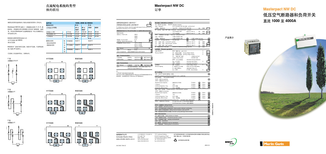
Masterpact MT低压空气断路器和负荷开关简化目录早期的 Masterpact 产品设立了世界范围空气断路器的新标准,多年后,许多制造厂也开发具有 Masterpact 革新特点如分断原理,模块化设计和复合材料的产品。
今天,施耐德电气又推出最新的 Masterpact MT 新产品,除了具有传统断路器特点之外 (抽出式,选择性和低维护性),它们又具有了体积优化,内置通讯和测量功能。
Masterpact MT 采用最新技术,增强了产品性能和安全性,是具有容易安装、用户界面友好、操作方便、设计容易的划时代产品。
Masterpact MT系列断路器已通过中国3C 认证及船级社认证。
56E 58880出色源于个性新型 M a s t e r p a c tMasterpact MT 七种分断类型N1 - 标准型,适用于分断低等级短路电流N2 - 适用于一般的应用场合H1 - 适用于分断工业环境的高等级短路电流或两台变压器并联运行的电气系统中H1b - 适用于短路电流较大的工业行业H2 - 高性能型,适用于可能产生非常高短路电流的重工业领域H3 - 适用于既需要高性能的分断能力,又需要高水平配合的场合L1 - 具有高限流能力,用以保护馈电单元或当变压器额定功率提高时,提高开关柜的性能水平易集成于通信网Masterpact MT 可集成于一般管理系统中,优化设备的操作和维护。
通信结构是开放式的。
通过接口可适用于任何协议。
负荷开关负荷开关直接由断路器派生出来的,具有高质量和高性能的特点。
根据型号,负荷开关有 3 种 HA 、NA 和 HF 。
HF 安装了瞬时保护装置,防止短路时合闸。
一旦合闸,负荷开关不再提供保护与普通开关一样。
负荷开关常用于母联上。
特殊应用p 1000V 交流Masterpact NW H10 型断路器和负荷开关,800A 到 4000A, 3 极或 4 极,抽屉式,型号为 H10。

施耐德客服电话电动机启动负载类型施耐德的EASYPACT和MASTERPACT断路器的区别是什么?COMPACT首先两者均是低压断路器(1000V以下)先说Masterpact, 该系列是框架式断路器。
框架额定电流从800A----6300A不等。
Masterpact系列分M系列和MT系列。
M系列自1986年上市,2002年淘汰退市停产。
MT系列自2001年上市至今任然作为施耐德公司的主力框架断路器在产。
Easypact系列是塑壳式断路器,这里需要加入另一个系列Compact系列,Compact系列是施耐德公司的主力标准型塑壳式断路器。
Easypact系列是Compact系列的经济型产品。
举个例子,任何品牌的汽车都会有高配版、中配版、低配版。
那么Easypact系列就是低配版的。
Compact系列的壳架额定电流从100A----630A, 同样Easypact系列也是100A----630A的壳架额定电流。
施耐德NSX、NS塑壳断路器区别?NSX是NS停产后的代替产品。
原NS断路器壳架电流是从80~1600,80~630俗称小塑壳,绝大多数已停产,由NSX80~630代替;630b~1600为大塑壳,现在仍在生产。
NSX只有80~630的产品。
小塑壳NS由NSX代替后尺寸和安装尺寸完全相同,但断路器的门开孔的尺寸不一样。
总体来说,NSX可完全代替NS,且部分高级保护功能有所增强施耐德NS100 3P3t,4P3t 什么意思,NSX 的3P2D 3P3D 4P4D 4P3D、4P3D+N/2、OSN什么意思?Q “3P、4P”表示3极、4极断路器,“D”表示中性线的保护动作值。
Q 4D——中性线的保护动作值以Ir为基准;Q 3D+N/2——中性线的保护动作值以0.5Ir为基准;Q 3D——中性线无保护;Q 中性线过保护,保护值为各相保护电流值的1.6倍。
其中,NSX中的3P2D表示3极壳架(3P),其中2极具备保护(2D);同理,3P3D表示3极壳架(3P),所有3极都具备保护(3D);4P4D表示4极壳架(4P),所有4极都具备保护(相和中性线具备相同的保护阈值)同样,NS也是如此(要说明的是NSX是NS的升级版)“t”表示中性线的保护动作值。

Masterpact MT低压空气断路器和负荷开关简化目录早期的 Masterpact 产品设立了世界范围空气断路器的新标准,多年后,许多制造厂也开发具有 Masterpact 革新特点如分断原理,模块化设计和复合材料的产品。
今天,施耐德电气又推出最新的 Masterpact MT 新产品,除了具有传统断路器特点之外 (抽出式,选择性和低维护性),它们又具有了体积优化,内置通讯和测量功能。
Masterpact MT 采用最新技术,增强了产品性能和安全性,是具有容易安装、用户界面友好、操作方便、设计容易的划时代产品。
Masterpact MT系列断路器已通过中国3C 认证及船级社认证。
56E 58880出色源于个性新型 M a s t e r p a c tMasterpact MT 七种分断类型N1 - 标准型,适用于分断低等级短路电流N2 - 适用于一般的应用场合H1 - 适用于分断工业环境的高等级短路电流或两台变压器并联运行的电气系统中H1b - 适用于短路电流较大的工业行业H2 - 高性能型,适用于可能产生非常高短路电流的重工业领域H3 - 适用于既需要高性能的分断能力,又需要高水平配合的场合L1 - 具有高限流能力,用以保护馈电单元或当变压器额定功率提高时,提高开关柜的性能水平易集成于通信网Masterpact MT 可集成于一般管理系统中,优化设备的操作和维护。
通信结构是开放式的。
通过接口可适用于任何协议。
负荷开关负荷开关直接由断路器派生出来的,具有高质量和高性能的特点。
根据型号,负荷开关有 3 种 HA 、NA 和 HF 。
HF 安装了瞬时保护装置,防止短路时合闸。
一旦合闸,负荷开关不再提供保护与普通开关一样。
负荷开关常用于母联上。
特殊应用p 1000V 交流Masterpact NW H10 型断路器和负荷开关,800A 到 4000A, 3 极或 4 极,抽屉式,型号为 H10。
Interlocking trip indicator with remote reset in Magnum low voltage circuit breakersON THE EQUIPMENT(2) ALWAYS DE-ENERGIZE PRIMARY AND SECONDARY CIRCUITS IF A CIRCUITBREAKER CANNOT BE REMOVED TO A SAFE WORK LOCATION(3) DRAWOUT CIRCUIT BREAKERS SHOULD BE LEVERED (RACKED) OUT TO THEDISCONNECT POSITION.(4) ALL CIRCUIT BREAKERS SHOULD BE SWITCHED TO THE OFF POSITION ANDMECHANISM SPRINGSDISCHARGED.FAILURE TO FOLLOW THESE STEPS FOR ALL PROCEDURES DESCRIBED INTHIS INSTRUCTION LEAFLET COULD RESULT IN DEATH, BODILY INJURY, ORPROPERTY DAMAGE.BE FOLLOWED. OBSERVE THE FIVE SAFETY RULES.• DISCONNECTING;• ENSURE THAT DEVICES CANNOT BE ACCIDENTALLY RESTARTED;• VERIFY ISOLATION FROM THE SUPPLY;• EARTHING AND SHORT-CIRCUITING; AND;• COVERING OR PROVIDING BARRIERS TO ADJACENT LIVE PARTS.DISCONNECT THE EQUIPMENT FROM THE SUPPLY. USE ONLY AUTHORIZEDSPARE PARTS IN THE REPAIR OF THE EQUIPMENT. THE SPECIFIED MAIN-TENANCE INTERVALS AS WELL AS THE INSTRUCTIONS FOR REPAIR ANDEXCHANGE MUST BE STRICTLY ADHERED TO PREVENT INJURY TO PERSONNELAND DAMAGE TO THE SWITCHBOARD.2Instructional Leaflet IL2A12995Effective December 2021Interlocking trip indicator with remote reset in Magnum lowvoltage circuit breakersEATON Section 1: General informationA red, pop out mechanical trip indicator is an optional feature locatedabove the trip unit on the breaker’s front faceplate. In the event the trip unit trips the breaker on an overcurrent condition, or by an enhanced protection feature (if programmed, available on Digitrip 1150+ and PXR 25), the red trip flag releases and “pops” out toprovide local visual indication. This trip indication is always in addition to any LED trip indication provided by the trip unit.The remote reset trip indicator comes equipped with mechanical interlocking features. These features mechanically lock the breaker after it has tripped and prevent the breaker from being re-closed until the trip indicator has been reset.The remote reset trip indicator can be reset by applying a control voltage to the electromagnetic coil enclosed in the accessory device. After allowing sufficient time to reset the trip indicator, the control voltage is cutoff by a timing board also enclosed in the accessory device. The control voltage cannot, however, be continuously applied to the device to allow the board to reset and be ready for the next “event”. It is recommended that the control voltage not be applied to the secondary terminals any longer than 5 seconds.This product is intended for use in Magnum circuit breakers with PXR or Digitrip trip units.ote: N The proper control voltage of the device is marked on the accessory device.ote: N All images show a Magnum circuit breaker with a PXR trip unit unless stated otherwise. Some components, such as the trip unit, not shown for clarity.Required tools• ¼” (10mm) socket drive (with torque measuring capabilities)• 10mm socket• Phillips head screwdriver (#2 recommended)•Dremmel saw (or similar device used for removing front cover prongs)ote: N This is only required when retrofitting this accessory into a Magnum breaker produced prior to August 2011.•Wire cutters (for removal of any necessary wire ties)Kit parts identificationRefer to Figure 1 for visual identification of the parts listed below:A. Trip indicator (1)B. Trip indicator push rod (1)C. Trip unit mounting plate for Digitrip 520 model (1)D. M3.5 x 13 hi-lo screw (2)E. M3.5 flat washer (2)F . Accessory kit labels (1)G. Wire ties (2)(A)(C)(F)(B)(E)(D)Figure 1. Contents of kit 2C15799Section 2: Installation of remote reset trip indicator kitProceed with the following steps:Step 1: Remove the front cover by unscrewing the hex head captive bolts (4 for 3-pole, 6 for 4-pole) that join the cover to the breaker housing using a 10mm ¼ inch drive socket. Then hold the charge handle down approximately 45 degrees to pull off the cover. Step 2: Place the trip indicator option label (F) on the front cover nameplate space located under “Accessories”. Using a Dremmel saw (or similar tool), remove the two notches in the top right corner of the front cover as shown in the figure.ote: N The notches must be removed in order to replace the front cover with the remote reset trip indicator installed.3Instructional Leaflet IL2A12995Effective December 2021Interlocking trip indicator with remote reset in Magnum low voltage circuit breakersEATON Figure 2. Step 1 and 2.Step 3: To simplify the installation and avoid inadvertent damage to the trip indicator push rod (B), the push rod should be installed in the breaker first by inserting one hooked-end of the push rodFigure 3. Step 3.Step 4: Connect the trip indicator (A) to the already attached push rod (B) from step 3 by carefully rotating the trip indicator onto the upper hook end of the push rod as shown. Keep in mind that the lower hook end of the push rod must ultimately point to the rear.Figure 4. Step 4.Step 5: If the installed trip unit is a Digitrip Model 520 trip unit, skip this step and proceed directly to step 6. If the installed trip unit is a Model 1150 trip unit, complete this step as outlined below and then proceed to step 8. If the installed trip unit is a PXR trip unit, skip this step and proceed to step 7. Remove the trip unit retaining spring from the upper left hand corner of the trip unit mounting deck. Mount the completed trip indicator assembly from step 4 to the top two posts of the trip unit’s mount-ing deck directly above the Model 1150 trip unit using the supplied hardware (two M3.5 x 13 Hi-Lo Screws (D), two M3.5 flat washers (E)) as shown. Torque 0 18-22 in-lbs. (2.0-2.5 N-m). Connect the trip indicator assembly remote reset wires to the secondary connector as referenced in T able 1.Figure 5. Step 5.4Instructional Leaflet IL2A12995Effective December 2021Interlocking trip indicator with remote reset in Magnum lowvoltage circuit breakersEATON Figure 6. Step 5.Step 6: If the installed trip unit is a Model 520 trip unit and a metal plate is already mounted to the two top posts of the trip unit’smounting deck, remove the plate completely. Position the completed trip indicator assembly from step 4 to the top two mounting posts of the deck. Replace the trip unit mounting plate with the supplied trip unit mounting plate (C) and secure the trip indicator between the posts and the plate using the removed mounting screws (There are extra screws supplied in the kit). Torque to 18-22 in-lbs. (2.0-2.5 N-m). Connect the trip indicator assembly remote reset wires to the secondary connector as referenced in T able 1.Figure 7. Step 6.Step 7: If the installed trip unit is a PXR trip unit, remove the plate completely. Position the completed trip indicator assembly from step 4 to the top two mounting posts of the deck. Reinstall the trip unit mounting plate and secure the trip indicator between the posts and plate using the removed mounting screws. Torque to 18-22 in-lbs. (2.0 - 2.5 N∙m). Connect the trip indicator assembly remote reset wires to the secondary connector as referenced in T able 1.Keep in mind that the trip indicator (A) is shown here without the push rod (B) attached for mounting orientation reasons only.Figure 8. Step 6.ote: N Terminal maps for the secondary connectors are located on top of the secondary connectors.Step 8: After installation, verify that the trip indicator assembly remains latched when the breaker is operated with the push buttons. Verify that the mechanical trip indicator trips when the breaker opens with the trip actuator. Verify the breaker cannot be reclosed with the trip indicator in the tripped (popped out) position. Finally, verify that the trip indicator assembly resets when the proper control voltage is applied to the secondary terminals.Step 9: Static trip actuator test: As the trip latch rotates slowly, the trip actuator must not trip before the breaker trips. The indicator may not trip during this test but the breaker must trip.Step 10: Connect the wires from the overcurrent trip switch (bell alarm) to the secondary connector, referencing T able 2, in keeping with the wiring markings. Terminal maps for the secondary connec-tions are located on top of the secondary connectors.Verify that the overcurrent trip switches are in the open position when the trip indicator has tripped. Verify that the overcurrent trip switches are in the closed position when the trip indicator has not trippedStep 11:Reinstall front cover removed in Step 1.5Instructional Leaflet IL2A12995Effective December 2021Interlocking trip indicator with remote reset in Magnum low voltage circuit breakersEATON Notes.Eaton1000 Eaton Boulevard Cleveland, OH 44122 United States © 2021 EatonAll Rights ReservedPrinted in USAPublication No. IL2A12995H03/ TBG 001557 December 2021Eaton is a registered trademark.All other trademarks are propertyof their respective owners. Interlocking trip indicator with remote reset in Magnum low voltage circuit breakersInstructional Leaflet IL2A12995 Effective December 2021Disclaimer of warranties and limitation of liabilityThe information, recommendations, descriptions, and safety notations in this document are based on Eaton Corporation’s (“Eaton”) experience and judgment, and may not cover all contingencies. If further information is required, an Eaton sales office should be consulted.Sale of the product shown in this literature is subject to the terms and conditions outlined in appropriate Eaton selling policies or other contractual agreement between Eaton and the purchaser.THERE ARE NO UNDERSTANDINGS, AGREEMENTS, WARRANTIES, EXPRESSED OR IMPLIED, INCLUDING WARRANTIES OF FITNESS FOR A PARTICULAR PURPOSE OR MERCHANTABILITY, OTHER THAN THOSE SPECIFICALLY SETOUT IN ANY EXISTING CONTRACT BETWEEN THE PARTIES. ANY SUCH CONTRACT STATES THE ENTIRE OBLIGATION OF EATON. THE CONTENTS OF THIS DOCUMENT SHALL NOT BECOME PART OF OR MODIFY ANY CONTRACT BETWEEN THE PARTIES. In no event will Eaton be responsible to the purchaser or user in contract, in tort (including negligence), strict liability, or otherwise for any special, indirect, incidental, or consequential damage or loss whatsoever, including but not limited to damage or loss of use of equipment, plant or power system, cost of capital, loss of power, additional expenses in the use of existing power facilities, or claims against the purchaser or user by its customers resulting from the use of the information, recommendations, and descriptions contained herein.The information contained in this manual is subject to change without notice.。
低压开关柜运行操作规程一、低压电气抽屉柜操作规程1.将抽屉柜插入到工作位置(1)检查抽屉柜内线路完好,断路器无损坏,接触器状态正常。
(2)确认断路器在分闸位置,抽屉柜面板上操作把手指示“抽出”位置,将抽屉柜放入柜内导轨上,推入开关柜内。
(3)将操作把手插入操作孔中,顺时针方向转动把手,操作把手指示“工作位置”。
然后合上主回路把手,合上断路器,面板上指示灯亮。
2.将抽屉柜从工作位置抽出(1)确认断路器在分闸位置,将抽屉柜面板上操作把手转动到“抽出”位置。
(2)将抽屉柜拉出开关柜内。
二、开关柜送电/停电操作规程送电前,请先确认现场各项交接试验正常、功能调试正常,且全部合格。
1.开关柜送电操作规程(1)开关柜送电前的检查工作a)检查各抽屉柜内的电缆接线头良好,螺丝应锁紧;断路器、接触器状态正常;b)检查各抽屉柜内无不相干物件和工具;c)检查抽屉柜内熔断器是否正常;d)检查低压设备处于送电前的准备状态。
(2)开关柜送电的操作步骤顺时针转动抽屉柜上断路器把手,使把手与地面垂直。
2.开关柜停电的规范操作规程(1)开关柜停电前的准备工作确认清楚要断开的设备是否停止运行。
(2)开关柜停电的操作步骤a)逆时针转动抽屉柜上断路器把手,使把手与地面平行。
b)悬挂“禁止合闸,有人工作”警示牌。
三、框架断路器操作规程1.框架断路器停电操作步骤(1)观察进线三相无电流指示;(2)按柜面分闸按钮,框架断路器跳闸。
跳闸后,断路器窗口显示0字,柜面绿灯亮,红灯灭;(3)将框架断路器摇至隔离位置;(4)悬挂“禁止合闸,有人工作”警示牌。
2.框架断路器送电操作步骤(1)取下“禁止合闸,有人工作”警示牌;(2)检查框架断路器二次电缆接线头良好,螺丝锁紧,柜内无异物;(3)将框架断路器摇至工作位置;(4)按柜面合闸按钮,断路器窗口显示1字,柜面红灯亮,绿灯灭;(5)观察进线三相电压指示。
四、低压开关柜倒闸操作规程表4.8.1 低压开关柜倒闸分类表1. 将Ⅰ、Ⅱ段分别供电改为Ⅱ段供电:合上Ⅰ、Ⅱ段母联断路器,Ⅰ段进线断路器退出运行。