ltm 1300
- 格式:pdf
- 大小:4.37 MB
- 文档页数:18
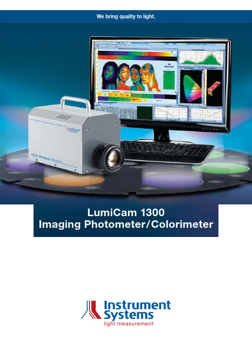
We bring quality to light.light measurementlight measurement Instrument Systems GmbH Neumarkter Str. 8381673 Munich, GermanyTel.: +49 89/45 49 43-0Fax: +49 89/45 49 43-11E-mail: info@ 2As an imaging measurement system, LumiCam 1300 captures the luminance and color distributions of screens or multifunction displays within seconds. At the same time, the instrument analyses complex image content. Each of the 1370 x 1020 pixels of the high-resolution CCD sensor is assigned a calibrated luminance and color value. This provides a two-dimensional image which presents the spatially resolved measured values coded for brightness and color.The LumiCam 1300 models are ideal for the following applications:Measurement of luminance and color distributions of display and control elements in vehiclesHomogeneity analysis of flat screens or electronic information signsHomogeneity analysis of lamps and luminaires used in general lightingCapturing luminance distribution curves for small lamps and luminairesThe LumiCam 1300 is a proven measurement system in the areas of research, development, and quality assur-ance, as well as in production. The LumiCam Software supports the various areas of application with specific functions that allow a wide range of different measuring tasks to be carried out fast.Benefits of imaging systemsSubstantial time-savings with analysis of the deviceunder test within seconds. The slow point-by-point scanning of the sample with a single-spot photometer is e l iminatedIntegrated image processing functions facilitate fast analysis of luminance and color distributionsSmall footprint and minimum training requirementFast Recording of Luminance and Color DistributionsAnalysis of luminance homogeneity at an LCD displayKey features at a glanceThree models: Mono, Color, Advanced 1370 x 1020 effective pixelsWide measuring range of 0.1 mcd/m2 to 109 cd/m2 Automatic signal level of the CCD sensorMultiple exposure delivers five decades of dynamic range in one imageTechnical Overview Functionality | Applications | Specifications3The LumiCam 1300 familyInstrument Systems offers the LumiCam 1300 in three versions.LumiCam 1300 MonoCompact luminance camera for reliable and precise measurementsLumiCam 1300 ColorVersion with additional color filters for luminance and co l or measurementsLumiCam 1300 AdvancedAdvanced camera concept for maximum accuracy in luminance and color measurementInterchangeable objective lenses with adjustable focus and aperture offer solutions to accommodate a wide range of different requirements for measuring distance, measuring resolution and image field size. Objective lenses withfocal lengths ranging from 14 mm to 100 mm are supplied for all three models. The measuring range of luminance can be expanded using appropriate density filters.*With optional test setup LC-LVKThe LumiCam 1300 familyOverview of the softwarePowerful software complements the LumiCam 1300. It calculates all the relevant quantities. Luminance distribution RGB color imageColor coordinates (x, y and u', v') Color temperature Color uniformityDominant wavelength and color saturation ContrastVersatile analytical tools, such as spotmeter, polygon, line or 3D box, permit comprehensive evaluation of the measured data. The LumiCam software offers the possibility of false-color presentation for particularly impressive visualization of the values obtained. The palette editor is another useful tool for individual adjustment of the false-color output. The integratedexport and reporting functions of the LumiCam software provide the user with convenient documentation and allow further processing of the measurement results. Individually defined analysis schemes can be saved as templates and are available for recurring measurement tasks.Examples of evaluation tools of the LumiCam softwareA LumiCam DLL is also supplied for implementing cus-tomer-specific measuring functions. Instrument Systems offers a package of LabVIEW VIs (visual instruments) in order to address the LumiCam DLL via LabVIEW. In this way, automated tests can be carried out in production applications.Accessories: Objective lenses and density filterspolygonboxPhotometric and colorimetric quantitiesPhotometric and colorimetric quantities are essential for the evaluation of light with regard to brightness and color impression under consideration of human perception. Pa-rameters like color coordinates, correlated color tempera-ture, and dominant wavelength are calculated from the tristimulus values X, Y, Z. These are obtained by weightingLumiCam 1300 – Outstanding Measuring Accuracya given light spectrum with the eye sensitivity curves x ¯, y ¯, z ¯ of CIE from 1931. The curves are defined such that Y corresponds to luminance.LumiCam 1300 ColorIn imaging colorimetry, the device under test (DUT) is imaged on a CCD sensor using an objective lens and the V() or tristimulus filters mounted behind. Many cameras have three filters for calculating the tristimulus values X, Y, Z, corresponding to the three sensitivity curves x ¯, y ¯, z ¯. However, the function x ¯ has two spectrally-disjoint areas which a single filter can only poorly represent.The LumiCam 1300 Color therefore has two separate filters for x ¯ as standard, one each for the blue and red wavelength range. This renders more accurate measure-ment results compared with colorimeters based on only three filters.The matching quality of the filters is characterized by the V() mismatch index f 1'. The LumiCam 1300 Color achieves excellent values for this specification. In order to assure the matching quality, the spectral character-istics of all optical components are measured and theirEye sensitivity curves x ¯, y ¯, z ¯ (CIE 1931)Technical Overview Functionality Applications | Specifications4accuracy is checked during the production process. As the market leader for spectral light measurement systems, we have specific expertise and extremely high require-ments in this area.Furthermore, each LumiCam 1300 is individually calibrat-ed so that all the properties of the objective lens and the sensor can be captured. A dedicated calibration is carried out for each combination of aperture, filter, and objective lens with the aim of guaranteeing the best possible measuring accuracy over the entire image field (flat-field correction).The LumiCam 1300 AdvancedMotivated by the goal of further improving measurement accuracy, the LumiCam 1300 concept has been devel-oped further. In particular, Instrument Systems wanted to achieve optimal measurement results for LED based test objects. The resulting LumiCam 1300 Advanced now features a total of six filters. Alongside the four filters of the LumiCam 1300 Color (X'1, X'2, Y', Z'), two additional filters (K', L ') are used. Moreover, an optimized algorithm serves to calculate the tristimulus values.Color coordinate deviation of test LEDs for measurement with the LumiCam 1300 AdvancedFilter wheel of the LumiCam 1300 AdvancedHowever, as well as increasing the measurement accu-racy, additional filters also lengthen the measuring time required by the system. The LumiCam 1300 Advanced provides an optimum solution between excellent mea-suring accuracy and the attainable measuring speed.If necessary, the LumiCam 1300 Advanced can beoperated like a LumiCam 1300 Mono or LumiCam 1300 Color – with analogous measuring times and accuracies. The individual operating mode is easily selected using the software.Matrix optimization for the LumiCam 1300 AdvancedRecording data in six channels (X’1, X’2, Y', Z', K', L ') to determine three parameters (X, Y, Z) results in a redun-dancy for their calculation. An optimized 3x6 adaption matrix is used for determining the tristimulus values from the six output channels. In this way, the technologically caused residual error of the filter adjustment is eliminat-ed. Patent is pending for this procedure. The adaptation matrix is defined individually for each LumiCam 1300 Advanced in the calibration process and optimizes the accuracy of the relevant quantities.After completing the calibration, a set of 3 white and 16 colored LEDs is used to check each LumiCam 1300 Advanced for compliance with the specifications.The higher accuracy of the LumiCam 1300 Advanced in determining the color coordinates is also reflected in the calculation of the dominant wavelength.Deviation of the dominant wavelength for different test LEDs (comparison ofLumiCam 1300 Color and LumiCam 1300 Advanced)5Precise Characterization of Display Elements in VehiclesThe LumiCam 1300 is ideal for detailed characterization of panel graphics, control elements, and dashboards in the automotive sector. The LumiCam software permits fast and user-friendly evaluation of test and measure-ment results. It provides the following tools:SpotmeterAny number of spotmeters of any size can be positioned in the captured luminance and color images of the LumiCam 1300. The luminance, color coordinates, cor-related color temperature and the dominant wavelengthare calculated automatically inside a spotmeter. Individ-ually definable pass/fail criteria are displayed directly and show whether or not the measured values are within the desired range.LineThe line function allows easy analysis of the variation in luminance along a path. A line can simply be determined with this object. The function is ideal for analysis ofintersections over an entire display surface or for as-sessing the homogeneity within display elements.Spotmeter evaluation toolLine evaluation toolline #0026Technical Overview | Functionality Applications Specificationsspotmeter #003spotmeter #002spotmeter #001spotmeter #004testThe software generates an associated luminance profile in a separate window along the selected line. A cursor can be positioned at any point in this profile for further analysis.PolygonFlexible markings can be generated in order to define individual boundaries for measuring areas. Each pixel within the polygon tool is classified to an object (target) or background on the basis of its luminance value. The target and background are automatically visualized withPolygon evaluation toolcolor highlighting. The underlying threshold values are stored in the luminance histogram and can be individu-ally adjusted. This allows the software to carry out a fast and simple analysis of the measuring areas for contrast and minimum, maximum and average luminance, of the foreground and background areas.3D BoxThe 3D tool provides a particularly impressive visualiza-tion of a luminance distribution. Any size of rectangularEvaluation tool 3D boxBlack Mura Module: Focus adjustmentBlack Mura Module: Evaluationbox can be used to mark the frame for analysis. The 3D box can be easily rotated in all three spatial axes.Black Mura ModuleThe Black Mura Module is used for homogeneity evalu-ation of liquid crystal displays (LCDs). Process fluctua-tions during panel manufacturing may lead to variations in layer thickness. Burn-in effects can also occur with sustained fixed-images. These are only two possible causes for the occurrence of changes in luminance and color coordinates in liquid crystal displays. A reproduc-ible uniform evaluation of such changes is describedby the measurement specifications of the …Uniformity Measurement Standard for Displays“ drawn up by the German automobile industry. These specifications are implemented in the Black Mura Module of the LumiCam software.The Black Mura Module adopts a user-friendly approach and leads the user step-by-step through the test sequence for homogeneity analysis of displays in a wide range of different technologies.7polygon #001Extensive Testing of DisplaysEvaluation of the color reproduction of an FPDExtensive tests are carried out on all types of display, e. g. LC and OLED displays, in development, production and quality control. Characterization with imaging sys-tems, such as the LumiCam 1300, is becoming increas-ingly important. Numerous measuring functions, such as homogeneity analyses, can be carried out quickly by capturing the test object in a single image combined with the integrated image processing functions. The figure shows an example of a color analysis for a flat-panel display. The evaluation of the positioned spotmeter is carried out immediately. The green or red highlighted rows show whether the measured color values are in the previously defined target area.Production control of screensThe LumiCam 1300 can be used for automated homo- geneity analyses of screens in production with the assis-tance of the LumiCam DLL. The available Windows pro- gram library allows the customer to implement individual test requirements and to define specific pass/fail criteria. This permits immediate classification of the tested dis-plays, e. g. by luminance and color-coordinate charac- teristics.Electronic displaysThe LumiCam 1300 is an ideal measurement system for capturing and evaluating illuminated graphics and lettering on all types of panel and display. The advanced technology permits fast characterization of electronic display panels, traffic signs, illuminated advertising signs and warning lamps.One example is provided by emergency lights for escape routes. They are subject to strict requirements for unifor-mity and color of the backlit surfaces. The specifications for mean luminance and for contrast of graphics and background areas are regulated by standards. A simple analysis can be carried out with the polygon tool in the LumiCam software. The limits for foreground and back- ground areas can be easily defined in the luminance histo- gram. A visible delineation of both areas and immediate output of the measured values is carried out automati-cally.spotmeter #001spotmeter #002spotmeter #003spotmeter #0048Technical Overview | Functionality Applications SpecificationsModern technologies such as OLEDs and LEDs also open up new perspectives for general lighting. LumiCam 1300 is a fast and compact measuring system which permits comprehensive testing of lamps, modules and complete luminaires for color temperature, color rendering and spatial radiation pattern.Homogeneity analyses of flat panel lightsWhen designers use flat luminaires, e. g. OLEDs, the appearance of the surface of the luminaire is extremely important. A homogeneous lighting field gives the ob- server a high-quality impression. The LumiCam 1300 is ideal for the corresponding homogeneity analyses of color coordinates and luminance.Measurement of luminous intensity distribution curvesA special test setup (LC-LVK) for the LumiCam 1300 measurement system has been developed for fastdetermination of luminous intensity distribution curves, spatial homogeneity of the color coordinates, and the color temperature. It is comprised of an optical bench, a light-permeable screen, a holder for the LumiCam 1300 and a fixture for the luminaire.The system is suitable for small to mid-sized light sources, like single LEDs, LED modules, LED light engines, retrofit lamps and small luminaires.The test object illuminates the light-permeable screen. The LumiCam 1300 measures the luminance distribution arising on the screen from which the spatial radiation patterns are calculated. They can be recorded up to an opening angle of 65°. The typical measuring time is lessHomogeneity analysis of color temperature in an OLEDTest setup for luminous intensity distribution curveImage of luminous intensity distribution curves with the LC-LVK test setupThe LumiCam 1300 in General Lightingthan one minute, independently of how many luminous intensity distribution curves have been calculated from the data obtained. The angle-dependent differences in the color coordinates can be determined in the same way. The extremely short measuring times in comparison with a goniometer make the test setup ideal for a number of settings including incoming goods inspection or quality assurance.Zhaga-compliant luminance measurementsThe specifications of the Zhaga Consortium define specific requirements for LED modules, in order toguarantee their interchangeability, independently of the manufacturer. The LumiCam 1300 permits Zhaga-compliant luminance measurements of LED lamps and LED luminaires.9Specifications Technical Specifications10Technical Specifications for LensesOrdering InformationInstrument Systems is continually working to develop and improve products. Any technical changes, errors or misprints do not form grounds for compensation. The company’s terms of delivery and payment apply in all other respects.All specifications above are related to the 50 mm lens with aperture 2.8, unless otherwise specified.1 With optional light distribution curve test setup (LC-LVK).2 SNR 25:1, spotmeter radius 10 pixels.3 0.1 mcd/m 2 at 30 s exposure time and aperture 1.4 and SNR 10:1; 100,000 cd/m 2 at 1 ms exposure time and aperture 16 (both without ND filters).4 With optionally available OD4 filter.5 Specification of LumiCam 1300 Advanced in the extended measurement range identical with LumiCam 1300 Color (e. g. regarding accuracy of color coordinates).6 Values for aperture 1.4 and auto-ranging mode; first measurement may take longer; with LumiCam 1300 Advanced a higher accuracy can be achieved in comparison to LumiCam 1300 Color, but then measurement time takes longer.7 For open aperture; traceable to PTB standard according to ISO 17025; extended measuring uncertainty applied to a twofold standard deviation.8 Verified using a test set of color LEDs (peak wavelength between 449 nm and 640 nm) and white LEDs (3000 K to 5000 K); measured max/min tolerance with respect to reference spectrometer.9 2 at 10 cd/m 2, auto-ranging mode and within a series of measurements.10 Average of 10 x 10 pixels.11 Y-filter (V()-filter).12 Verified using a test set of color glass filters and white halogen lamp.13 For narrowband radiation (e. g. LED).14 20 ... 25 °C for specified measurement accuracy.All data are typical values11。


AusstattungEquipmentEquipement • Equipaggiamento Equipamiento •OáîðóäîâàíèåKranfahrgestellRahmen Eigengefertigte, verwindungssteife Stahl-konstruktion aus hochfestem Feinkorn-Baustahl.Abstützungen Vier hydraulisch ausklappbare Schwenk-holme mit hydraulischen Abstützzylindern. Motor8-Zylinder-Diesel, Fabrikat Liebherr, TypD9508 A7, wassergekühlt, Leistung 500 kW(680 PS) bei 1900 min-1. Max. Drehmoment3000 Nm bei 1100 min-1 – 1500 min-1.Abgasemissionen entsprechend Richtlinien97/68/EG Stufe 3 und EPA/CARB Tier 3.Kraftstoffbehälter: 600 l.Getriebe Automatisches Schaltgetriebe mit Drehmo-mentwandler und Intarder direkt am Getriebeangebaut, Fabrikat ZF, Typ TC-TRONIC mit12 Vorwärtsgängen und 2 Rückwärtsgängen,Verteilergetriebe, zweistufi g mit sperrbaremVerteilerdifferential.Achsen Schwere Kranfahrzeugachsen.Alle 9 Achsen gefedert und lenkbar.Achsen 1, 2, 4 und 5 sind Planetenachsen.Achsen 2 und 4 mit Längsdifferentialsperre.Achsen 4 und 5 mit Querdifferentialsperre. Federung Alle Achsen sind hydropneumatisch gefedertmit automatischer Niveauregulierung.Achsdruckausgleich zwischen den Achs-paaren. Federung hydraulisch blockierbar. Bereifung18fach, alle Achsen einzeln bereift.Reifengröße: 14.00 R 25.Lenkung ZF-Hydrolenkung, 2-Kreisanlage mit hydrau-lischer Servoeinrichtung, auf die mechanischmiteinander verbundenen Achsen 1 – 5 wirkend.Bei Straßenfahrt werden die Achsen 6 – 9elektrohydraulisch gelenkt und ab 30 km/hwerden die Achsen 6 + 7 auf Geradeausfahrtgestellt und blockiert. Die Achsen 8 + 9 werdengeschwindigkeitsabhängig bis 60 km/h “aktiv”gelenkt und über 60 km/h auf Geradeausfahrtgestellt. Lenkung entsprechend EG-Richtlinien70/311 EWG.Bremsen Betriebsbremse: Allrad-Servo-Druckluft-bremse, alle Achsen mit Scheibenbremsen,2-Kreisanlage.Zusatzbremsen: Auspuffklappenbremse mitZBS, Telma-Wirbelstrombremse, Intarder amGetriebe.Handbremse: Federspeicher auf alle Räderder 3. bis 8. Achse wirkend.Fahrerhaus Großräumige Kabine in Stahlblechausführungmit Komfortausstattung, gummielastischaufgehängt, Sicherheitsverglasung.Elektr. Anlage Moderne Datenbus-Technik, 24 VoltGleichstrom, 2 Batterien mit je 170 Ah,Beleuchtung nach StVZO.Kranantrieb Diesel-hydraulisch mit Axialkolben-Verstell-pumpen mit Servosteuerung und Leistungs-regelung im geschlossenen Kreislauf fürHeben, Drehen und Verstellen der Gitter-spitze. Axialkolbenpumpen im offenenKreislauf für Wippen und Teleskopieren. Steuerung Elektronisch durch die LICCON-Anlage. Zwei4fach Handsteuerhebel mit vibrierendemBewegungsmelder. Fußschalter für Tele-skopieren. Stufenlose Regulierung allerKranbewegungen.Hubwerk Axialkolben-Verstellmotor, Liebherr-Seilwindemit eingebautem Planetengetriebe undfederbelasteter Haltebremse.Wippwerk 2 Differentialzylinder mit Sicherheitsrück-schlagventil.Drehwerk 2 Drehwerke, jeweils bestehend aus Hydro-motor, Planetengetriebe, Drehwerksritzel undfederbelasteter Haltebremse.Krankabine Faserverbundwerkstoff, großes Sichtfeld,höhenverstellbar, nach hinten neigbar undzum Einsteigen hydraulisch absenkbar. Sicherheits-einrichtungenLICCON-Überlastanlage, Testsystem, Hub-endbegrenzung, Sicherheitsventile gegenRohr- und Schlauchbrüche.Ballast Gesamtballast 202 t, bestehend aus:1 Grundplatte 22 t, 16 Teile à 10 t, 4 Teile à 5 t.Hydraulische Ballastiereinrichtung (Option). Teleskopausleger Alle Teleskope separat ausschiebbar überdas Schnelltakt-TeleskopiersystemTELEMATIK.Variante 1: Auslegerlänge 19,9 m - 55 m inkl.T3-Adapter und T3-Kopf (363 t).Variante 2: Auslegerlänge 18,3 m - 100 minkl. T7-Kopf (213 t).Elektr. Anlage Moderne Datenbus-Technik, 24 VoltGleichstrom, 2 Batterien mit je 170 Ah.KranoberwagenRahmen Eigengefertigte, verwindungssteife Schweiß-konstruktion aus hochfestem Feinkorn-Bau-stahl. 3-reihige Rollendrehverbindung. Kranmotor6-Zylinder-Diesel, Fabrikat Liebherr, TypD936L A6, wassergekühlt, 270 kW (367 PS)bei 1800 min-1, max. Drehmoment 1720 Nmbei 1300 min-1. Kraftstoffbehälter: 300 l.ZusatzausrüstungTeleskopausleger-abspannung YBestehend aus Abspannbock mit 2 Seil-winden, anbaubar am 55 m bzw. 100 mlangen Teleskopausleger, in Transportstellungabklappbar.Exzenter E Inkl. 6 m Televerlängerung. Teleskopausleger-Verlängerung 6 m und 10 m Gitterstück.Gitterspitzen Feste Gitterspitze 6,5 m – 60,5 m.Hydraulische Verstellung von 0° – 60° (Option).Wippbare Gitterspitze 18 m – 126 m.2. Hubwerk Axialkolben-Verstellmotor, Liebherr-Seilwindemit eingebautem Planetengetriebe undfederbelasteter Haltebremse.3. Hubwerk mitVerstellfl ascheAxialkolben-Verstellmotor, Liebherr-Seilwindemit eingebautem Planetengetriebe undfederbelasteter Haltebremse, zum Verstellender wippbaren Gitterspitze.Auslegerselbst-montage 4 Abstützzylinder.Weitere Zusatzausrüstung auf Anfrage.Ausstattung EquipmentEquipement • Equipaggiamento Equipamiento • OáîðóäîâàíèåOther items of equipment available on request.Crane carrierFrameLiebherr-manufactured, torsionally rigid steel construction made from high-tensile fi ne-grain steel. Triple-roller slewing rim.Outriggers Four hydraulic swing-out beams with hydraulic support jacks.Engine8-cylinder Diesel, make Liebherr, type D9508 A7, watercooled, output 500 Kw (680 h.p.) at 1900 min -1. Max. torque 3000 Nm at 1100 min -1 – 1500 min -1. Exhaustemissions acc. to 97/68/EG stage 3 and EPA/CARB Tier 3. Fuel reservoir: 600 l.TransmissionAutomatic transmission with torque converter and intarder fi tted directly to the gear unit, manufactured by ZF , type TC -TRONIC with 12 forward and 2 reverse gears, transfer case with locking central differential.AxlesHeavy-duty crane-truck axles. All nine axles sprung and steerable. Axles 1, 2, 4 and 5 are planetary axles. Axles 2 and 4 have longitudinal differential lock. Axles 4 and 5 have transverse differential lock.SuspensionAll axles with hydropneumatic suspension and automatic levelling system. Load equalization between the axle pairs.The suspension can be locked hydraulically.Tyre equipment 18 tyres, all axles equipped with single tyres.Size of tyres: 14.00 R 25.SteeringZF power steering, two pump circuits with hydraulic servo system effective on the mechanically connected axles 1 – 5.When driving on road, axles 6 – 9 areelectro-hydraulically steered and, at 30 km/h and above, axles 6 + 7 are moved into straight-ahead position and fi xed. Axles 8 + 9 are speed-dependently ‚actively‘ steered at speeds of up to 60 km/h and set to go straight ahead when travelling over 60 km/h. Steering in accordance with EC guidelines 70/311 EWG.BrakesService brake: all-wheel servo air brake; disc brakes for all axles; two pump circuits.Additional brakes: exhaust brake with ZBS (additional brake system), Telma-type eddy-current brake, intarder in gearbox.Hand brake: spring-action effective on all wheels of axles 3 – 8.Driving cabSpacious and comfortable sheet steel cab mounted on rubber shock absorbers, safety glass windows.Electrical systemModern data bus technique, 24 Volt DC,2 batteries of 170 Ah each, lighting according to traffi c regulations.Crane superstructureFrameLiebherr-manufactured, torsionally rigidsteel construction made from high-tensile fi ne-grain steel. Triple-roller slewing rim.Crane engine6-cylinder Diesel engine, make Liebherr, type D936L A6, watercooled, output 270 kW (367 HP) at 1800 min -1, max. torque 1720 Nm at 1300 min -1. Fuel reservoir: 300 l.Crane driveDiesel-hydraulic, with axial piston variable displacement pumps, with servo-control and capacity control operating in closed circuit for hoisting, slewing and luffi ng of lattice jib, axial piston pumps, operating in open circuit for luffi ng and telescoping.Crane controlElectronic via LICCON system. Two 4-way hand control levers with vibrating movement indicator. Foot switch for telescopic action. Stepless control of all crane movements.Hoist gearAxial piston variable displacement motor, Liebherr hoist drum with integrated planetary gear and spring-loaded static brake.Luffi ng gear 2 differential rams with safety check valve.Slewing gear2 slewing gears, consisting of hydraulic motor, planetary gear, slewing pinion and spring-loaded static brake each.Crane cabFibre-composite material, large fi eld of vision, height-adjustable, tilts backwards and can be hydraulically lowered for ease of entry.Safety devicesLICCON safe load indicator, test system, hoist limit switches, safety valves against rupture of pipes and hoses.CounterweightTotal ballast: 202 t, comprising: 1 base plate 22 t, 16 10-t parts, 4 5-t parts.Hydraulic ballast system (optional).Telescopic boomAll telescopic parts may be separately slid out by means of rapid-cycle TELEMATIK telescoping system.Variant 1: boom lengths: 19.9 m – 55 m incl. T3 adapter and T3 head (363 t).Variant 2: boom lengths: 18.3 m – 100 m incl. T7 head (213 t).Electric systemModern data bus technique, 24 Volt DC, 2 batteries of 170 Ah each.Complementary equipmentGuying system for telescopic boom Y Consists of gantry with 2 hoist drums, attachable to 55-m or 100-m telescopic boom; fold away for transport.Eccentric EIncl. 6-m telescopic extension.Telescopic boom extension 6-m and 10-m lattice ttice jibsFixed lattice jib: 6.5 m – 60.5 m.Hydraulic adjustment from 0° – 60° (optional). Luffi ng fl y jib: 18 m – 126 m.2nd hoist gearVariable axial piston motor, Liebherr hoist drum with built-in planetary gear and static brake.3rd hoist gear withluffi ng blockVariable axial piston motor, Liebherr hoist drum with built-in planetary gear and static brake, for adjusting luffi ng fl y jib.Self-assembly boom 4 support jacks.Ausstattung EquipmentEquipement • Equipaggiamento Equipamiento • OáîðóäîâàíèåAutres équipements supplémentaires sur demande.Châssis porteurChâssisFabrication Liebherr, construction en caisson indéformable, en acier à grain fi n haute résistance.Stabilisateurs Quatre poutres déployables hydrauliquement avec vérins de calage hydrauliques.MoteurMoteur diesel, 8 cylindres, fabriqué parLiebherr, de type D9508 A7, à refroidissement par eau, de 500 kW (680 ch) à 1900 min -1.Couple max. 3000 Nm à 1100 min -1 – 1500 min -1.Emissions des gaz d‘échappement conformes aux directives 97/68/EG partie 3 et EPA/CARB Tier 3.Capacité du réservoir à carburant: 600 l.Boîte de vitesseBoîte automatique avec convertisseur de couple et ralentisseur, montés directement sur la boîte, de marque ZF, type TC-TRONIC avec 12 rapports AV et 2 AR, boîte de transfert avec blocage de différentiel.EssieuxEssieux spéciaux lourds. Tous les 9 essieux sont suspendus et directeurs. Essieux 1, 2, 4 et 5 sont à train planétaire. Essieux 2 et 4 sont pourvus de blocage des différentiels longitudinaux. Essieux 4 et 5 sont pourvus de blocage des différentiels transversaux.SuspensionTous les essieux sont suspendus hydropneu-matiquement avec mise à niveau etéquilibrage entre essieux automatiques. Suspension blocable hydrauliquement.Pneumatiques 18 roues à monte simple. Taille: 14.00 R 25.DirectionDirection hydraulique ZF, 2 circuits avec servocommande hydraulique, action sur les essieux 1 - 5 liés mécaniquement.En mode de déplacement sur route, direction électrohydraulique des essieux 6 – 9 et conduite en ligne droite activée pour les essieux 6 - 7 à partir de 30 km/h. Direction …active“ des essieux 6 + 7 en fonction de la vitesse jusqu‘à 60 km/h, et au-delà de 60 km/h conduite en ligne droite activée. Direction conforme à la directive européenne 70/311 EWG.FreinsFrein de service : servo-frein pneumatique pour toutes les roues, tous les essieux avec freins à disques, 2 circuits.Freins supplémentaires : frein avec clapet sur échappement avec ZBS, frein TELMA, ralentisseur monté sur boîte de vitesse.Frein à main : accumulateur à ressort, action sur toutes les roues des essieux 3 à 8. CabineCabine spacieuse, en tôle d’acier, équipe-ment «grand confort», suspendue sur silent blocs, vitrage de sécurité.InstallationélectriqueTechnique moderne de transmission de don-nées par BUS de données, courant continu 24 Volts, 2 batteries de 170 Ah chacune, éclairage conforme au code de la route.Partie tournanteChâssisFabrication Liebherr, construction soudée indéformable, en acier à grain fi n haute résistance. Couronne d‘orientation à triple rangée de rouleaux.MoteurDiesel 6 cylindres, marque Liebherr, type D936L A6, refroidi par eau, puissance 270 kW (367 ch) à 1800 min -1, couple max. 1720 Nm à 1300 min -1.Capacité du réservoir à carburant: 300 l.EntraînementDiesel hydraulique avec à pompes à débit variable servo commandées à régulation de puissance en circuit fermé pour les treuils et l’orientation. Pompes à débit variable en circuit ouvert pour le relevage de fl èche et le télescopage.Commande Electronique via le dispositif LICCON. Deuxleviers de commande à 4 positions avec détecteur vibrant de mouvement. Bouton au pied pour le télescopage. Régulationcontinue de tous les mouvements de la grue.Treuil Moteur hydraulique à cylindrée variable, treuilde marque Liebherr avec réducteurplanétaire à frein d’arrêt à lamelles intégrées.Relevage de fl èche 2 vérins différentiels avec clapet anti-retourde sécurité.Orientation 2 mécanismes d’orientation, composés d’unmoteur hydraulique, d’un réducteur planétaire,d’un pignon d’orientation et d’un frein à lamelles.Cabine de grue Matériaux composites, visibilitépanoramique, réglable en hauteur, inclinable vers l‘arrière et possibilité d‘abaissement hydraulique pour faciliter l‘accès.Sécurités Contrôleur de charge LICCON, système test,fi n de course crochet haut, clapets de sécurité en cas de ruptures de fl exibles.Contrepoids Contrepoids total 202 t, composé de :1 plaque de base 22 t, 16 éléments de 10 t chacun, 4 éléments de 5 t chacun.Dispositif de lestage hydraulique (en option).Flèche télescopique Chaque élément peut être télescopéindividuellement à l‘aide du système de télescopage séquentiel rapide TELEMATIK.Variante 1: Longueur de fl èche 19,9 m – 55 m avec adaptateur T3 et tête T3 (363 t).Variante 2: Longueur de fl èche 18,3 m – 100 m avec tête T7 (213 t).Circuit électrique Technique moderne de transmission de don-nées par BUS de données. Courant continu24 Volts, 2 batteries de 170 Ah chacune.Equipement optionnelHaubanage de fl èche YComposé du chevalet de haubanage avec2 treuils à câble, montage possible sur la fl èche télescopique de 55 m ou 100 m, rabattable hydrauliquement en position de transport.Axe excentrique E Avec extension de fl èche de 6 m.Rallonge de fl èche télescopique Elément en treillis de 6 m et 10 m.FléchettesFléchette treillis fi xe de 6,5 m – 60,5 m. Déploiement hydraulique entre 0° – 60° (en option). Fléchette treillis à volée variable 18 m – 126 m.Deuxième treuilMoteur à cylindrée variable et pistons axiaux, treuil à câble Liebherr avecréducteur planétaire intégré et frein d‘arrêt commandé par ressort.Troisième treuil avec train de moufl ageMoteur à cylindrée variable et pistons axiaux, treuil à câble Liebherr avecréducteur planétaire intégré et frein d‘arrêt commandé par ressort, pour le déploiement de la fl échette treillis à volée variable.Montage autonome de la fl èche 4 vérins de calage.Ausstattung EquipmentEquipement • Equipaggiamento Equipamiento • OáîðóäîâàíèåAltri equipaggiamenti fornibili a richiesta.AutotelaioTelaioDi produzione Liebherr, struttura di tipo scatolato, in acciaio a grana fi ne ad alta rigidità torsionale.Stabilizzatori Quattro travi di stabilizzazione ad apertura idraulica con cilindri idraulici stabilizzatori.MotoreDiesel a 8 cilindri, marca Liebherr, tipo D9508 A7, raffredato ad acqua, potenza 500 kW (680 CV) a 1900 giri/min., coppia massima 3000 Nm al regime di 1100 giri/min –1500 giri/min.Emissioni gas di scarico in base alle direttive CE 97/68 Livello 3 e EPA/CARB Tier 3.Capacità del serbatoio carburante: 600 l.CambioCambio automatico ZF tipo TC-TRONIC con convertitore di coppia e Intarder montati direttamente sul cambio, 12 marce in avanti e 2 retromarce, riduttore ripartitore con differenziale bloccabile.AssiAssi autogrù per carichi pesanti.Tutti 9 gli assi sono dotati di sospensioni e sono sterzanti. Asse 1, 2, 4 e 5 sono assi epicicloidali. Asse 2 e 4 con blocco differenziale longitudinale. Asse 4 e 5 con blocco differenziale trasversale.SospensioniTutti gli assi con sospensioneidropneumatica bloccabile idraulicamente ed un sistema di livellamento automatico. Il carico viene ripartito tra le coppie di assi.PneumaticiTutti gli assi sono equipaggiati con pneumatico singolo. 18 gomme. Dimensione: 14.00 R 25.SterzoSterzo ZF idraulico, 2 circuiti servoidraulici, che agisce meccanicamente su assi 1 – 5collegati tra di loro. Su strada vengono sterzati idraulicamente gli assi 6 – 9 e dalla velocità di 30 km/h gli assi 6 + 7 vengono bloccate in traiettoria diritta. Sterzo a norma in base alle direttive CE 70/311 EWG.FreniFreno di servizio: pneumatico, servoassistito, a doppio circuito, freno a disco agente su tutti gli assi. Freno addizionale: valvola agente su impianto di scarico con ZBS, freno elettromagnetico Telma, Intarder sul cambio. Freno a mano: di tipo meccanico agente dall‘asse 3 all‘asse 8.Cabina guidaCabina spaziosa in lamiera d‘acciaio zincato, montata su sospensione elastica, con vetratura di sicurezza.Impianto elettricoDi nuova concezione, utilizza la tecnica del bus dati, 24 V corrente continua, 2 batterie da 170 A, illuminazione e segnalazione visiva secondo le norme per la circolazione.TorrettaTelaioDi produzione Liebherr, struttura di tiposcatolato, in acciaio a grana fi ne ad alta rigidità torsionale. Ralla a 3 fi le di cuscinetti.MotoreDiesel a 6 cilindri, marca Liebherr, tipo D936L A6, raffreddato ad acqua, potenza 270 kW (367 CV) a 1800 giri/min, coppia massima 1720 Nm al regime di 1300 giri/min.Capacità del serbatoio carburante: 300 l.Impianto idraulicoDiesel-idraulico con pompe a pistoni assiali a cilindrata variabile con servocomando e regolazione di potenza in circuito idraulico chiuso per sollevamento, rotazione e regolazione del falcone.Pompe a pistoni assiali in circuito idraulico aperto per brandeggio e sfi lo andoElettronico grazie al sistema LICCON. Due leve manuali a 4 manovre con indicatore vibroacustico di movimento. Pedale per azionare sfi lo telescopico. Regolazionegraduale di tutte le movimentazioni della gru. Argani di sollevamentoMotore a cilindrata variabile e pistoni assiali, tamburo dell‘argano con riduttoreepicicloidale incorporato e freno di arresto multidisco meccanico.Sollevamento braccio 2 cilindri differenziali con valvola di sicurezza di non ritorno.Rotazione2 gruppi di rotazione, ognuno costituito da idromotore, epicicloidale, pignone gruppo di rotazione e freno di arresto caricato a molla.Cabina di manovraRealizzata in alluminio con vetratura di sicurezza, unità di comando e di controllo.Cabina reclinabile. Durante il trasporto su strada la cabina gru è ruota posteriormente.Dispositivi di sicurezza Limitatore di carico elettronico LICCON, test system, interruttori fi ne corsa sollevamento, valvole di sicurezza.ContrappesoContrappeso totale 202 t, composto da:1 piastra base 22 t, 16 piastre da 10 t ciascuna, 4 piastre da 5 t ciascuna.Agganciamento idraulico del contrappeso (Optional).Braccio telescopicoTutti gli elementi telescopici sfi lanoseparatamente grazie al sistema TELEMATIK. Variante 1: Lunghezza braccio 19,9 m – 55 m incl. adattatore T3 e testa T3 (363 t).Variante: Lunghezza braccio 18,3 m – 100 m incl. testa braccio T7 (213 t).Impianto elettricoDi nuova concezione, utilizza la moderna tecnica dei bus dati, 24 V corrente continua, 2 batterie da 170 A.Equipaggiamento addizionaleSistema di tirantatura per il braccio telescopico Y Costituito da un cavalletto d‘ancoraggio con 2 argani, montabili su braccio da 55 m e braccio lungo 100 m, ribaltabileidraulicamente durante il trasporto.Excenter E Incl. 6 m prolunga tralicciata braccio.Prolungamentobraccio telescopico Elemento tralicciato 6 m e 10 m.Falcone tralicciato Falcone fi sso tralicciato 6,5 m – 60,5 m.Regolazione idraulica da 0° a 60° (optional). Falcone a volata variabile 18 m – 126 m.2° argano di sollevamento Motore a cilindrata variabile e pistoni assiali, tamburo dell‘argano con riduttore epicicloidaleincorporato e freno di arresto multidisco.3° argano con fl angia Motore a cilindrata variabile e pistoni assiali, tamburo dell‘argano con riduttore epicicloidaleincorporato e freno di arresto multidisco per regolazione del falcone a volata variabile.Montaggioautomatico del braccio 4 cilindri stabilizzatoriAusstattung EquipmentEquipement • Equipaggiamento Equipamiento • OáîðóäîâàíèåOtro equipamiento bajo pedido.ChasisBastidor Fabricado por Liebherr en acero de grano fi no de alta resistencia, resistente a la torsión.Estabilizadores Cuatro vigas hidráulicas de apoyo en cruz. MotorDiesel 8 cilindros, marca Liebherr, tipo D9508 A7, refrigerado por agua, potencia 500 kW (680 CV) a 1900 rpm. Par máximo 3000 Nm a 1100 rpm – 1500 rpm, gestión de motor electrónica con técnica de bus de datos. Emisión de gases de escapeconforme a las directivas 97/68/CE nivel 3 y EPA/CARB Tier 3.Depósito de combustible: 600 l.Caja de cambiosCaja de cambio automática con convertidor e intarder montado directamente en la caja, fabricación ZF, Tipo TC-TRONIC de 12 velo-cidades delanteras y 2 traseras, caja transfer con bloqueo de diferencial.EjesEjes de chasis de servicio pesado. Suspensión y dirección en los nueve ejes. Ejes 1, 2, 4 y 5 son ejes planetarios. Ejes 2 y 4 con diferencial de bloqueo longitudinal. Ejes 4 y 5 con diferencial de bloqueo transversal.SuspensiónTodos los ejes están provistos de suspensión hidroneumática con regulación automática de nivel. Compensación de presión entre los pares de ejes. Suspensión bloqueable por sistema hidráulico.Cubiertas18 cubiertas, montaje de rueda simple en todos los ejes.Tamaño de cubiertas: 14.00 R 25.DirecciónSistema de dirección ZF, doble circuito con sistema servo-hidráulico en los ejes 1 – 5, ejes conectados mecánicamente.En conducción por carretera, los ejes 6 – 9se manejan electrohidráulicamente, los ejes 6 + 7 quedan centrados y fi jadosautomáticamente al sobrepasar los 30 km/h. Los ejes 8 + 9 se manejan como …dirección activa“ en función de la velocidad hasta los 60 Km/h, fi jándose también en línea recta al rebasarlos. Dirección conforme a norma EC 70/311 EWG.FrenosFreno de servicio: servofreno por aire com-primido a todas las ruedas; frenos de disco en todos los ejes; doble circuito.Frenos adicionales: freno motor con ZBS (sistema de freno adicional), Telma, intarder integrado en caja de cambios.Freno de mano: por acumuladores de muelle en todas las ruedas de los ejes 3 a 8.CabinaCabina espaciosa fabricada totalmente en chapa de acero, montada sobre suspensión elástica, acristalamiento de seguridad.Sistema eléctricoBus de datos, 24 V corriente continua, 2 baterías de 170 Ah cada una, alumbrado conforme a la norma alemana.SuperestructuraBastidorFabricado por Liebherr en acero de granofi no de alta resistencia, resistente a la tor-sión. Corona de giro de 3 hileras de rodillos.Motor grúaDiesel 6 cilindros, marca Liebherr, tipo D936L A6, refrigerado por agua, potencia 270 kW (367 CV) a 1800 rpm, par máximo 1720 Nm a 1300 rpm.Depósito de combustible: 300 l.Accionamiento grúaDiesel hidráulico con bombas de pistones axiales de caudal variable con servomando y regulación de potencia con circuito cerrado para elevación, giro y regulación del plumín de celo-sía. Bombas de pistones axiales con circuito abierto para basculamiento y telescopaje.Mando grúa Electrónico, através de sistema LICCON. Dospalancas de cuatro direcciones con indicador de movimiento por vibración. Pedal para telescopaje. Regulación sin escalonamiento de todos los movimientos de grúa.Cabrestante Motor de pistones axiales de regulación,tambor de cabrestante con reductor de planetarios integrado y freno de retención accionado por muelle.Elevación 2 cilindros diferenciales con válvula deseguridadMecanismo de giro 2 mecanismos de giro, cada uno de loscuales consta de motor hidráulico, engranaje planetario, piñón de mecanismo de giro y freno de retención accionado por muelle.Cabina Estructura en fi bra reforzada, gran campode visión, regulable en altura, inclinable hacia atrás y posibilidad de descenderla hidráulicamente para facilitar el accesoDispositivos de seguridad Limitador de cargas LICCON, sistema de verifi cación, fi nal de carrera de subida depasteca, válvulas de seguridad contra la rotura de tuberías y latiguillos.Contrapeso Contrapeso total: 202 t, comprendiendo:una placa base de 22 t, 16 placas de 10-t, 4 placas de 5-t.Sistema de contrapeso hidráulico (opcional).Pluma telescópica Todos los tramos telescopables de formaindependiente con sistema de telescopaje rápido TELEMATIK.Variante 1: longitudes de pluma: 19.9 m – 55 m incl. adaptador T3 y cabezal T3 (363 t).Variante 2: longitudes de pluma: 18.3 m –100 m incl. cabezal T7 (213 t).Instalación eléctrica Bus de datos, 24 V corriente continua,2 baterías a 170 Ah cada una.Equipamiento adicional/alternativoArriostramiento pluma telescópica Y Formado por caballete de tensión con dos cabrestantes, instalable en plumatelescópica de 55 m y 100 m, plegable en posición de transporte.Exzenter E Incl.extensión telescópica de 6 m.Prolongación de pluma telescópica Tramo de celosía de 6 m y 10 m.Plumines de celosía Plumín fi jo: 6.5 m – 60.5 m. Angulaciónhidráulica 0° – 60° (opcional). Plumín abatible: 18 m – 126 m.2° Cabrestante Motor de pistones axiales de desplazamientovariable, cabrestante Liebherr con engranaje planetario incorporado y freno de retención accionado por muelle.3er mecanismo de elevación con motón de ajuste Motor de pistones axiales de desplazamiento variable, cabrestante Liebherr con engranaje planetario incorporado y freno de retenciónaccionado por muelle, para ajuste del plumín abatible.Automontaje de pluma. 4 cilindros de apoyo.。

1dc1884afaDescriptionLTM9009-14, LTM9008-14, LTM9007-14,LTM9006-14: 14-Bit, 125/105/80/65/40/25Msps Octal ADC FamilyDC1884 supports the LTM ®9011 high speed, octal ADC family.The versions of the 1884A demo board are listed in Table 1. Depending on the required resolution and sample rate, the DC1884 is supplied with the appropriate ADC. The circuitry on the analog inputs is optimized for analog inputPARAMETERCONDITIONVALUESupply Voltage – DC1884A Depending on Sampling Rate and the A/D Converter Provided, This Supply Must Provide Up to 700mA Optimized for 3.5V[3.3V to 6V Minimum/Maximum]Analog Input Range Depending on SENSE Pin Voltage 1V P-P to 2V P-P Logic Input VoltagesMinimum Logic High 1.3V Maximum Logic Low0.6VLogic Output Voltages (Differential)Nominal Logic Levels (100Ω Load, 3.5mA Mode)350mV/1.25V Common Mode Minimum Logic Levels (100Ω Load, 3.5mA Mode)247mV/1.25V Common Mode Sampling Frequency (Convert Clock Frequency)See Table 1Encode Clock Level Single-Ended Encode Mode (ENC – Tied to GND)0V to 3.6V Encode Clock Level Differential Encode Mode (ENC – Not Tied to GND)0.2V to 3.6VResolutionSee Table 1Input Frequency Range See Table 1SFDR See Applicable Data Sheet SNRSee Applicable Data Sheetperformance summaryfrequencies from 1MHz to 70MHz. Refer to the data sheet for proper input networks for different input frequencies. Design files for this circuit board are available at http://www.linear .com/demo/DC1884AL , L T , L TC, L TM, Linear Technology and the Linear logo are registered trademarks of Linear Technology Corporation. All other trademarks are the property of their respective owners.Table 1. DC1884 VariantsDC1884 VARIANTSADC PART NUMBER RESOLUTION MAXIMUM SAMPLE RATEINPUT FREQUENCY 1884A-A LTM9011-1414-Bit 125Msps 1MHz to 70MHz 1884A-B LTM9010-1414-Bit 105Msps 1MHz to 70MHz 1884A-C LTM9009-1414-Bit 80Msps 1MHz to 70MHz 1884A-D LTM9008-1414-Bit 65Msps 1MHz to 70MHz 1884A-E LTM9007-1414-Bit 40Msps 1MHz to 70MHz 1884A-FLTM9006-1414-Bit25Msps1MHz to 70MHz(T A = 25°C)2dc1884afaQuick start proceDureDC1884 is easy to set up to evaluate the performance of the LTM9011 family of A/D converters. For proper mea-surement equipment setup, refer to Figure 1 and follow the procedure explained in the following sections.Figure 1. Test Setup of DC1884DC1884A F01ANALOGINPUTSJUMPERS SHOWN INQuick start proceDureSetupIf a DC1371 data acquisition and collection system was supplied with the DC1884, follow the DC1371 Quick Start Guide to install the required software and to connect the DC1371 to the DC1884 and to a PC.DC1884 Board JumpersThe DC1884 board should have the following jumper set-tings as default positions (as per Figure 1):JP14: PAR/SER: Selects Parallel or Serial Programming Mode. (Default: Serial)Optional Jumpers AJ3 and J6: Term: Enables/Disable Optional Output Termination. (Default: Removed)JP5: I LVDS: Selects Either 1.75mA or 3.5mA of Output Current for the LVDS Drivers. (Default: Removed)JP1 and JP2: Lane: Selects Either 1-L ane or 2-L ane Output Modes (Default: Removed)Note: The DC1371 does not support 1-Lane operation. JP9: SHDN: Enables and Disables the LTM9011. (Default: Removed)JP8: WP: Enable/Disables Write Protect for the EEPROM. (Default: Removed)Note: Optional jumper should be left open to ensure proper serial configuration.Applying Power and Signals to the DC1884The DC1371 is used to acquire data from the DC1884. The DC1371 must first be connected to a powered USB port and have 5V applied power before applying 3.5V across the pins marked V+ and “GND” on the DC1884. DC1884 requires 3.5V for proper operation.The DC1884 demonstration circuit requires up to 700mA depending on the sampling rate and the A/D converter supplied.The DC1884 should not be removed or connected to the DC1371 while power is applied.Analog Input NetworkFor optimal distortion and noise performance, the RC network on the analog inputs may need to be optimized for different analog input frequencies. For input frequen-cies above 70MHz, refer to the LTM9011 data sheet for a proper input network.In almost all cases, filters will be required on both analog input and encode clock to provide data sheet SNR. The filters should be located close to the inputs to avoid reflections from impedance discontinuities at the driven end of a long transmission line. Most filters do not present 50Ω outside the passband. In some cases, 3dB to 10dB pads may be required to obtain low distortion.If your generator cannot deliver full-scale signals without distortion, you may benefit from a medium power amplifier based on a gallium arsenide gain block prior to the final filter. This is particularly true at higher frequencies where IC based operational amplifiers may be unable to deliver the combination of low noise figure and high IP3 point required. A high order filter can be used prior to this final amplifier, and a relatively lower Q filter used between the amplifier and the demonstration circuit.Encode ClockNote: Apply an encode clock to the SMA connector on the DC1884 demonstration circuit board marked “J2 CLK+.” As a default, the DC1884 is populated to have a single-ended input.For the best noise performance, the ENCODE input must be driven with a very low jitter, square wave source. The amplitude should be large, up to 3V P-P or 13dBm. When using a sinusoidal signal generator, a squaring circuit can be used. Linear Technology also provides demo board DC1075A that divides a high frequency sine wave by four, producing a low jitter square wave for best results with the LTM9011.3dc1884afaQuick start proceDureUsing bandpass filters on the clock and the analog input will improve the noise performance by reducing the wideband noise power of the signals. In the case of the DC1884 a bandpass filter used for the clock should be used prior to the DC1075A. Data sheet FFT plots are taken with 10 pole LC filters made by TTE (Los Angeles, CA) to suppress signal generator harmonics, non harmonically related spurs and broadband noise. L ow phase noise Agilent 8644B generators are used for both the clock input and the analog input.Digital OutputsData outputs, data clock, and frame clock signals are available on J1 of the DC1884. This connector follows the VITA-57/FMC standard, but all signals should be verified when using an FMC carrier card other than the DC1371. SoftwareThe DC1371 is controlled by the PScope system software that can be downloaded from the L inear Technology website at /software/.To start the data collection software, “PScope.exe,” which is installed by default to \Program Files\LTC\PScope\, double click the PScope icon or bring up the run window under the start menu, and browse to the PScope directory and select “PScope.”If the DC1884 is properly connected to the DC1371, PScope should automatically detect the DC1884 and configure itself accordingly.If everything is hooked up properly and a powered and suitable convert clock is present, clicking the “Collect” button should result in time and frequency plots displayed in the PScope window. Additional information and help for PScope is available in the DC1371 Quick Start Guide, and in the online help feature within the PScope program itself.Serial ProgrammingPScope has the ability to program the DC1884 serially through the DC1371. There are several options available in the LTM9011 family that are only available through serially programming. PScope allows all of these features to be tested.These options are available by first clicking on the “Set Demo Bd Options” icon on the PScope toolbar (Figure 2). This will bring up the menu shown in Figure 3.Figure 2. PScope ToolbarFigure 3. Demo Board Configuration Options4dc1884afa5dc1884afaInformation furnished by L inear Technology Corporation is believed to be accurate and reliable. However , no responsibility is assumed for its use. Linear Technology Corporation makes no representa-tion that the interconnection of its circuits as described herein will not infringe on existing patent rights.Quick start proceDureThis menu allows any of the options available for the LTM9011 family to be programmed serially. The LTM9011 family has the following options:Randomizer : Enables Data Output Randomizer .• Off (Default): Disables data output randomizer . • On: Enables data output randomizer .T wo’s Complement : Enables T wo’s Complement Mode.• Off (Default): Selects offset binary mode.• On: Selects two’s complement mode.Sleep Mode : Selects Between Normal Operation and Sleep Mode.• Off (Default): Entire ADC is powered and active. • On: The entire ADC is powered down.Channel 1 Nap : Selects Between Normal Operation and Putting Channel 1 in Nap Mode.• Off (Default): Channel 1 is active.• On: Channel 1 is in nap mode.Channel 2 Nap : Selects Between Normal Operation and Putting Channel 2 in Nap Mode.• Off (Default): Channel 2 is active.• On: Channel 2 is in nap mode.Channel 3 Nap : Selects Between Normal Operation and Putting Channel 3 in Nap Mode.• Off (Default): Channel 3 is active.• On: Channel 3 is in nap mode.Channel 4 Nap : Selects Between Normal Operation and Putting Channel 4 in Nap Mode.• Off (Default): Channel 4 is active.• On: Channel 4 is in nap mode.Output Current : Selects the LVDS Output Drive Current.• 1.75mA (Default): LVDS output driver current.• 2.1mA: LVDS output driver current.• 2.5mA: LVDS output driver current.• 3.0mA: LVDS output driver current.• 3.5mA: LVDS output driver current.• 4.0mA: LVDS output driver current.• 4.5mA: LVDS output driver current.Internal Termination : Enables L VDS Internal Termination.• Off (Default): Disables internal termination.• On: Enables internal termination.Outputs : Enables Digital Outputs.• Enabled (Default): Enables digital outputs. • Disabled: Disables digital outputs.Test P attern : Selects Digital Output Test Patterns. The desired test pattern can be entered into the text boxes provided.• Off (Default): ADC input data is displayed.• On: Test pattern is displayed.Once the desired settings are selected, click “OK” and PScope will automatically update the register of the device on the DC1884 demo board.6dc1884afaLinear Technology Corporation1630 McCarthy Blvd., Milpitas, CA 95035-7417(408) 432-1900 ● FAX : (408) 434-0507 ● www.linear .comLINEAR TECHNOLOGY CORPORA TION 2012LT 0117 • PRINTED IN USADEMONSTRATION BOARD IMPORTANT NOTICELinear Technology Corporation (LTC) provides the enclosed product(s) under the following AS IS conditions:This demonstration board (DEMO BOARD) kit being sold or provided by Linear Technology is intended for use for ENGINEERING DEVELOPMENT OR EVALUATION PURPOSES ONLY and is not provided by LTC for commercial use. As such, the DEMO BOARD herein may not be complete in terms of required design-, marketing-, and/or manµFacturing-related protective considerations, including but not limited to product safety measures typically found in finished commercial goods. As a prototype, this product does not fall within the scope of the European Union directive on electromagnetic compatibility and therefore may or may not meet the technical requirements of the directive, or other regulations.If this evaluation kit does not meet the specifications recited in the DEMO BOARD manual the kit may be returned within 30 days from the date of delivery for a full refund. THE FOREGOING WARRANTY IS THE EXCLUSIVE WARRANTY MADE BY THE SELLER TO BUYER AND IS IN LIEU OF ALL OTHER WARRANTIES, EXPRESSED, IMPLIED, OR STATUTORY, INCLUDING ANY WARRANTY OF MERCHANTABILITY OR FITNESS FOR ANY PARTICULAR PURPOSE. EXCEPT TO THE EXTENT OF THIS INDEMNITY, NEITHER PARTY SHALL BE LIABLE TO THE OTHER FOR ANY INDIRECT, SPECIAL, INCIDENTAL, OR CONSEQUENTIAL DAMAGES.The user assumes all responsibility and liability for proper and safe handling of the goods. Further, the user releases LTC from all claims arising from the handling or use of the goods. Due to the open construction of the product, it is the user’s responsibility to take any and all appropriate precautions with regard to electrostatic discharge. Also be aware that the products herein may not be regulatory compliant or agency certified (FCC, UL, CE, etc.).No License is granted under any patent right or other intellectual property whatsoever. LTC assumes no liability for applications assistance, customer product design, software performance, or infringement of patents or any other intellectual property rights of any kind.LTC currently services a variety of customers for products around the world, and therefore this transaction is not exclusive .Please read the DEMO BOARD manual prior to handling the product . Persons handling this product must have electronics training and observe good laboratory practice standards. Common sense is encouraged .This notice contains important safety information about temperatures and voltages. For further safety concerns, please contact a LTC application engineer.Mailing Address:Linear Technology 1630 McCarthy pitas, CA 95035Copyright © 2004, Linear Technology Corporation。
M-511⁄8 DIN Digital Panel RTD MetersThe DP63000-RTD meter accepts standard RTD inputs and precisely linearizes them into temperature readings. A full 4-digit display accommodates a wide range of temperature inputs. State-of-the-art digital circuitry virtually eliminates errors due to drift. The meter features a readout choice of either Fahrenheit or Celsius with 0.1 or 1° resolution. Display prompts and front panel buttons aid the operator through set-up and operation. Programmable digital filtering enhances the stability of the reading. All set-up data is stored in EEPROM, which will hold data for a minimum of 10 years without power. The meter provides a peak “HI” and valley “LO” reading memory with selectable capture delay time. The capture delay is used to prevent detection of false peak or valley readings that may occur during start-up or unusual process events. The peak and valley readings areDP63200-RTDU RTD Meter U 4-Digit, 14.2 mm (0.56") LEDU Accepts Standard 3-Wire 100 Ω RTD Sensors (ALPHA = 0.00385 or ALPHA =0.00392) U Conforms to ITS-90 StandardsU Selectable °F or °C with 0.1 or 1 Degree Display Resolution U P rogrammableTemperature Offset U Programmable Digital FilteringU Peak/Valley (High/Low Reading) Memory U NEMA 4X (IP65) Sealed Front BezelU Custom Units Overlay with BacklightOrdering Example: DP63200-RTD, RTD input, 85 to 250 Vac, 50/60 Hz.stored at power-down, allowing process limits to be monitored over any length of time. The meter has several built-in diagnostic functions to alert operators of any malfunction. Extensive testing of noise interference mechanisms and full burn-in makes the meter extremely reliable in industrial environments. The front bezel meets NEMA 4X (IP65) requirements for wash-down applications.Specifications Display: 4-digit, 14.2 mm H (0.56") LED, minus sign displayed for negative temperatures Power: 85 to 250 Vac, 50/60 Hz, 6 VA Isolation: 2300 Vrms for 1 minute between input and supply (300V working voltage)Resolution: 0.1 or 1°Range (Decimal Point Dependent): 0.1° Res: -199.9 to 850.0°C (-199.9 to 999.9°F) 1° Res: -200 to 850°C (-328 to 1562 °F)Lead Resistance Effect: 20 Ω max, 2.5 °C/Ω error for V exc and common lead unbalance Accuracy: 0.3°C, @ 23°C and 30 minute warm-up Reading Rate: 2.5 readings/s Response Time: 2 s to settle for step input (increases with programmable digital filtering)Low-Frequencey Noise Rejection: Normal Mode Rejection: 40 dB @ 50/60 Hz (may be improved by programmable digital filtering) Common Mode Rejection: 120 dB, DC to 50/60 Hz Environmental Conditions: Operating Temperature Range: 0 to 50°C (32 to 122°F) Storage Temperature Range: -40 to 80°C (-40 to 176°F) Operating and Storage Humidity: 85% max RH non-condensing from 0 to 50°C (32 to 122°F)Span Drift: 50 ppm/°C Zero Drift: 0.001°C/°C Altitude: Up to 2000 m (6562')Construction: This unit is rated for NEMA 4X (IP65) indoor use, 1 piece bezel/case, flame-resistant—panelgasket and mounting clip included Connections: High-compression, cage-clamp terminal block Dimensions: 104.1 D x 91.4 W x 44.5 mm H (4.10 x 3.50 x 1.75)Weight: 0.24 kg (0.65 lb)DP63200-RTD shown actual size.。
MBRM120LSurface MountSchottky Power Rectifier POWERMITE®Power Surface Mount PackageThe Schottky Powermite® employs the Schottky Barrier principle with a barrier metal and epitaxial construction that produces optimal forward voltage drop−reverse current tradeoff. The advanced packaging techniques provide for a highly efficient micro miniature, space saving surface mount Rectifier. With its unique heatsink design, the Powermite® has the same thermal performance as the SMA while being 50% smaller in footprint area, and delivering one of the lowest height profiles, < 1.1 mm in the industry. Because of its small size, it is ideal for use in portable and battery powered products such as cellular and cordless phones, chargers, notebook computers, printers, PDAs and PCMCIA cards. Typical applications are AC−DC and DC−DC converters, reverse battery protection, and “ORing” of multiple supply voltages and any other application where performance and size are critical.Features•Low Profile − Maximum Height of 1.1 mm•Small Footprint − Footprint Area of 8.45 mm2•Low V F Provides Higher Efficiency and Extends Battery Life •Supplied in 12 mm Tape and Reel•Low Thermal Resistance with Direct Thermal Path of Die on Exposed Cathode Heat Sink•ESD Ratings:Human Body Model, 3B u 16000 VMachine Model, C u 400 V•Pb−Free Packages are AvailableMechanical Characteristics:•Powermite® is JEDEC Registered as D0−216AA •Case: Molded Epoxy•Epoxy Meets UL 94 V−0 @ 0.125 in•Weight: 16.3 mg (Approximately)•Lead and Mounting Surface Temperature for Soldering Purposes: 260°C Maximum for 10 Seconds†For information on tape and reel specifications, including part orientation and tape sizes, please refer to our T ape and Reel Packaging Specifications Brochure, BRD8011/D.Device Package Shipping†ORDERING INFORMATIONMBRM120LT1POWERMITE3000/T ape & ReelMBRM120LT3POWERMITE12000/T ape & Reel MBRM120LT1G POWERMITE(Pb−Free)3000/T ape & ReelMBRM120LT3G POWERMITE(Pb−Free)12000/T ape & ReelMAXIMUM RATINGSRatingSymbol Value Unit Peak Repetitive Reverse Voltage Working Peak Reverse Voltage DC Blocking VoltageV RRM V RWM V R 20VAverage Rectified Forward Current (At Rated V R , T C = 135°C)I O 1.0A Peak Repetitive Forward Current(At Rated V R , Square Wave, 100 kHz, T C = 135°C)I FRM 2.0A Non−Repetitive Peak Surge Current(Non−Repetitive peak surge current, halfwave, single phase, 60 Hz)I FSM 50A Storage TemperatureT stg −55 to 150°C Operating Junction TemperatureT J −55 to 125°C Voltage Rate of Change (Rated V R , T J = 25°C)dv/dt10,000V/m sTHERMAL CHARACTERISTICSThermal Resistance, Junction−to−Lead (Anode) (Note 1)Thermal Resistance, Junction−to−Tab (Cathode) (Note 1)Thermal Resistance, Junction−to−Ambient (Note 1)R tjl R tjtab R tja3523277°C/WStresses exceeding Maximum Ratings may damage the device. Maximum Ratings are stress ratings only. Functional operation above the Recommended Operating Conditions is not implied. Extended exposure to stresses above the Recommended Operating Conditions may affect device reliability.1.Mounted with minimum recommended pad size, PC Board FR4, See Figures 9 & 10.ELECTRICAL CHARACTERISTICSMaximum Instantaneous Forward Voltage (Note 2), See Figure 2V FT J = 25°C T J = 85°C V(I F = 0.1 A) (I F = 1.0 A) (I F = 3.0 A)0.340.450.650.260.4150.67Maximum Instantaneous Reverse Current (Note 2), See Figure 4I R T J = 25°C T J = 85°CmA (V R = 20 V) (V R = 10 V)0.400.1025182.Pulse Test: Pulse Width ≤ 250 m s, Duty Cycle ≤2%.I F , I N SP S )i F , I N S T A N T A N E O U S F O R W A R D C U R R E N T (A M P S )Figure 1. Typical Forward Voltage Figure 2. Maximum Forward Voltage0.1v F , INSTANTANEOUS FORWARD VOLTAGE (VOLTS)101.0V F , MAXIMUM INSTANTANEOUS FORWARD VOLTAGE(VOLTS)0.10.70.30.50.90.10.70.30.50.9I R ,I R , R E V E R S E C U R R E N T (A M P S )Figure 3. Typical Reverse CurrentFigure 4. Maximum Reverse Current20V R , REVERSE VOLTAGE (VOLTS)V R , REVERSE VOLTAGE (VOLTS)5.01015205.01015P F O , A V E R A G E P O W E R D I S S I P A T I O N (W A T T S )I O , A V E R A G E F O R W A R D C U R R E N T (A M P S)Figure 5. Current DeratingFigure 6. Forward Power Dissipation457525T L , LEAD TEMPERATURE (°C)1.81.21.00.80.20I O , AVERAGE FORWARD CURRENT (AMPS)0.200.70.60.50.30.10 1.0551151051.40.41251.60.60.40.6 1.40.235658595T J , D E RC , C A P A C I T A N C E (p F )Figure 7. Capacitance Figure 8. Typical Operating Temperature Derating*12V R , REVERSE VOLTAGE (VOLTS)100010010V R , DC REVERSE VOLTAGE (VOLTS)102006.02.04.08.01012142.0 4.08.06.0* Reverse power dissipation and the possibility of thermal runaway must be considered when operating this device under any re-verse voltage conditions. Calculations of T J therefore must include forward and reverse power effects. The allowable operatingT J may be calculated from the equation:T J = T Jmax − r(t)(Pf + Pr) where r(t) = thermal impedance under given conditions,Pf = forward power dissipation, and Pr = reverse power dissipationThis graph displays the derated allowable T J due to reverse bias under DC conditions only and is calculated as T J = T Jmax − r(t)Pr,where r(t) = Rthja. For other power applications further calculations must be performed.201416181618R (T ), T R A N S I E N T T H E R M A L R E S I S T A N C E (N O R M A L I Z E D )R (T ), T R A N S I E N T T H E R M A L R E S I S T A N C E (N O R M A L I Z E D )T, TIME (s)1.01000.10.000011,0000.00010.0010.01 1.010Figure 9. Thermal Response Junction to Lead1000.10.00001T, TIME (s)0.00010.0010.01 1.010Figure 10. Thermal Response Junction to AmbientPACKAGE DIMENSIONSPOWERMITE CASE 457−04ISSUE DDIM MIN MAX MIN MAX INCHES MILLIMETERS A 1.75 2.050.0690.081B 1.75 2.180.0690.086C 0.85 1.150.0330.045D 0.400.690.0160.027F 0.70 1.000.0280.039H −0.05+0.10−0.002+0.004J 0.100.250.0040.010K 3.60 3.900.1420.154L 0.500.800.0200.031R 1.20 1.500.0470.059SNOTES:1.DIMENSIONING AND TOLERANCING PER ANSI Y14.5M, 1982.2.CONTROLLING DIMENSION: MILLIMETER.3.DIMENSION A DOES NOT INCLUDE MOLD FLASH,PROTRUSIONS OR GATE BURRS. MOLD FLASH,PROTRUSIONS OR GATE BURRS SHALL NOT EXCEED 0.15 (0.006) PER SIDE.0.50 REF 0.019 REFǒmm ǓSCALE 10:1SOLDERING FOOTPRINT**For additional information on our Pb−Free strategy and solderingdetails, please download the ON Semiconductor Soldering and Mounting Techniques Reference Manual, SOLDERRM/D.ON Semiconductor and are registered trademarks of Semiconductor Components Industries, LLC (SCILLC). SCILLC reserves the right to make changes without further notice to any products herein. SCILLC makes no warranty, representation or guarantee regarding the suitability of its products for any particular purpose, nor does SCILLC assume any liability arising out of the application or use of any product or circuit, and specifically disclaims any and all liability, including without limitation special, consequential or incidental damages.“Typical” parameters which may be provided in SCILLC data sheets and/or specifications can and do vary in different applications and actual performance may vary over time. All operating parameters, including “Typicals” must be validated for each customer application by customer’s technical experts. SCILLC does not convey any license under its patent rights nor the rights of others. SCILLC products are not designed, intended, or authorized for use as components in systems intended for surgical implant into the body, or other applications intended to support or sustain life, or for any other application in which the failure of the SCILLC product could create a situation where personal injury or death may occur. Should Buyer purchase or use SCILLC products for any such unintended or unauthorized application, Buyer shall indemnify and hold SCILLC and its officers, employees, subsidiaries, affiliates,and distributors harmless against all claims, costs, damages, and expenses, and reasonable attorney fees arising out of, directly or indirectly, any claim of personal injury or death associated with such unintended or unauthorized use, even if such claim alleges that SCILLC was negligent regarding the design or manufacture of the part. SCILLC is an Equal Opportunity/Affirmative Action Employer. This literature is subject to all applicable copyright laws and is not for resale in any manner.PUBLICATION ORDERING INFORMATIONPOWERMITE is a registered trademark of and used under a license from Microsemi Corporation.。
TCUT1300X01Document Number 84756Rev. 2.3, 20-Jul-07Vishay Semiconductors1Subminiature Dual Channel Transmissive Optical Sensor with DescriptionThe TCUT1300X01 is a compact transmissive sensor that includes an infrared emitter and two phototransistor detectors, located face-to-face in a surface mount package.Features•Product designed and qualified acc.AEC-Q101 for the automotive market •Package type: surface mount •Detector type: phototransistor •Dimensions:L 5.5 mm x W 4 mm x H 4 mm •Gap: 3 mm •Aperture: 0.3 mm•Channel distance (center to center): 0.8 mm •Typical output current under test: I C = 0.6 mA •Emitter wavelength: 950 nm•Lead (Pb)-free soldering released•L ead (Pb)-free component in accordance with RoHS 2002/95/EC and WEEE 2002/96/EC•Minimum order quantity: 2000 pcs, 2000 pcs/reelApplications•Automotive optical sensors•Accurate position sensor for encoder •Sensor for motion, speed and directionAbsolute Maximum RatingsT amb = 25°C, unless otherwise specified CouplerInput (Emitter)Output (Detector)ParameterT est conditionSymbol Value Unit Power dissipationT amb ≤ 25 °CP 150mW Ambient temperature range T amb - 40 to + 85°C Storage temperature range T stg - 40 to + 100°C Soldering temperaturein accordance with fig. 15T sd260°CParameterTest conditionSymbol Value Unit Reverse voltage V R 5V Forward current I F 25mA Forward surge current t p ≤ 10 µs I FSM 200mA Power dissipationT amb ≤ 25 °CP V75mWParameterT est conditionSymbol Value Unit Collector emitter voltage V CEO 20V Emitter collector voltage V ECO 7V Collector current I C 20mA Power dissipation T amb ≤ 25 °CP V75mW 2Document Number 84756Rev. 2.3, 20-Jul-07TCUT1300X01Vishay SemiconductorsElectrical CharacteristicsT amb = 25°C, unless otherwise specified CouplerInput (Emitter)Output (Detector)Switching CharacteristicsFigure 1. Power Dissipation Limit vs. Ambient Temperature050100150200P - P o w e r D i s s i p a t i o n (m W )T am b - Am b ient Temperat u re (°C)16538100755025ParameterTest conditionSymbol Min Typ.MaxUnit Collector current per channel V CE = 5 V , I F = 15 mA I C 300600µA Collector emitter saturationvoltageI F = 15 mA, I C = 0.05 mAV CEsat0.4VParameterTest conditionSymbol MinTyp.Max Unit Forward voltage I F = 15 mAV F 1.21.4V Reverse current V R = 5 VI R 10µA Junction capacitanceV R = 0 V , f = 1 MHzC j25pFParameterTest conditionSymbol Min Typ.MaxUnit Collector emitter voltage I C I C = 1 mA V CEO 20V Emitter collector voltage I E = 100 µAV ECO 7V Collector dark currentV CE = 25 V , I F = 0, E = 0I CEO1100nAParameterTest conditionSymbol MinTyp.Max Unit Rise time I C = 0.3 mA, V CE = 5 V ,R L = 100 Ω (see figure 2)t r 20.0150µs Fall timeI C = 0.3 mA, V CE = 5 V ,R L = 100 Ω (see figure 2)t f30.0150µsTCUT1300X01Document Number 84756Rev. 2.3, 20-Jul-07Vishay Semiconductors3Typical CharacteristicsT amb = 25°C, unless otherwise specifiedFigure 2. Test Circuit for t r and t fFigure 3. Switching Times10 %I FI C 96 11698t p pulse duration t d delay time t rrise time t on (= t + t )dr turn-on timet sstorage time t ffall time t off (=t s +t f )turn-off timeFigure 4. Forward Current vs. Forward Voltage Figure 5. Forward Voltage vs. Ambient TemperatureFigure6. Collector Current vs. Forward CurrentFigure 7. Collector Current vs. Collector Emitter Voltage 4Document Number 84756Rev. 2.3, 20-Jul-07TCUT1300X01Vishay SemiconductorsFigure 8. Collector Emitter Saturation Voltage vs.Ambient TemperatureFigure 9. Collector Current vs. Ambient Temperature Figure 10. Collector Dark Current vs. Ambient TemperatureFigure 11. Relative Collector Current vs. Horizontal DisplacementFigure 12. Relative Collector Current vs. Vertical DisplacementFigure13. Rise/Fall Time vs. Collector CurrentTCUT1300X01Document Number 84756Rev. 2.3, 20-Jul-07Vishay Semiconductors5Floor LifeLevel 1, acc. JEDEC, J-STD-020. No time limit.Reflow Solder ProfileReliability Tests in Reference to AEC-Q101 ReleaseFigure 14. Application exampleFigure15. Lead (Pb)-free Reflow Solder Profile acc. J-STD-020CTestCondition Duration Lot Size - Rejects High temperature storage T stg(max) = 100 °C 1000 h 3 x 50 pcs - 0 pcs Low temperature storage T stg(min) = - 40 °C 1000 h 3 x 50 pcs - 0 pcs T emperature cycling - 40 °C/+ 100 °C1000 x 3 x 77 pcs - 0 pcs H3TRB85 °C/85 % RH,Emitters: V R = 4 V , detectors: V CEO = 5 V 1000 h 3 x 77 pcs - 0 pcs Intermittent operational lifeEmitters: I F = 80 mA DC, detectors: V CE = 16 V,duty cycle: 2 min on, 2 min off, T amb = 25 °C1000 h (15000 cycles)3 x 77 pcs - 0 pcs 6Document Number 84756Rev. 2.3, 20-Jul-07TCUT1300X01Vishay Semiconductors Package Dimensionsin millimetersTCUT1300X01Document Number 84756Rev. 2.3, 20-Jul-07Vishay Semiconductors7Package Dimensionsin millimeters 8Document Number 84756Rev. 2.3, 20-Jul-07TCUT1300X01Vishay SemiconductorsOzone Depleting Substances Policy StatementIt is the policy of Vishay Semiconductor GmbH to1.Meet all present and future national and international statutory requirements.2.Regularly and continuously improve the performance of our products, processes, distribution and operatingsystems with respect to their impact on the health and safety of our employees and the public, as well as their impact on the environment.It is particular concern to control or eliminate releases of those substances into the atmosphere which are known as ozone depleting substances (ODSs).The Montreal Protocol (1987) and its London Amendments (1990) intend to severely restrict the use of ODSs and forbid their use within the next ten years. Various national and international initiatives are pressing for an earlier ban on these substances.Vishay Semiconductor GmbH has been able to use its policy of continuous improvements to eliminate the use of ODSs listed in the following documents.1.Annex A, B and list of transitional substances of the Montreal Protocol and the L ondon Amendmentsrespectively2.Class I and II ozone depleting substances in the Clean Air Act Amendments of 1990 by the EnvironmentalProtection Agency (EPA) in the USA3.Council Decision 88/540/EEC and 91/690/EEC Annex A, B and C (transitional substances) respectively. Vishay Semiconductor GmbH can certify that our semiconductors are not manufactured with ozone depleting substances and do not contain such substances.We reserve the right to make changes to improve technical designand may do so without further notice.Parameters can vary in different applications. All operating parameters must be validated for each customer application by the customer. Should the buyer use Vishay Semiconductors products for any unintended or unauthorized application, the buyer shall indemnify Vishay Semiconductors against all claims, costs, damages, and expenses, arising out of, directly or indirectly, any claim of personal damage, injury or death associatedwith such unintended or unauthorized use.Vishay Semiconductor GmbH, P.O.B. 3535, D-74025 Heilbronn, GermanyDocument Number: 91000Revision: 18-Jul-081DisclaimerLegal Disclaimer NoticeVishayAll product specifications and data are subject to change without notice.Vishay Intertechnology, Inc., its affiliates, agents, and employees, and all persons acting on its or their behalf (collectively, “Vishay”), disclaim any and all liability for any errors, inaccuracies or incompleteness contained herein or in any other disclosure relating to any product.Vishay disclaims any and all liability arising out of the use or application of any product described herein or of any information provided herein to the maximum extent permitted by law. The product specifications do not expand or otherwise modify Vishay’s terms and conditions of purchase, including but not limited to the warranty expressed therein, which apply to these products.No license, express or implied, by estoppel or otherwise, to any intellectual property rights is granted by this document or by any conduct of Vishay.The products shown herein are not designed for use in medical, life-saving, or life-sustaining applications unless otherwise expressly indicated. Customers using or selling Vishay products not expressly indicated for use in such applications do so entirely at their own risk and agree to fully indemnify Vishay for any damages arising or resulting from such use or sale. Please contact authorized Vishay personnel to obtain written terms and conditions regarding products designed for such applications.Product names and markings noted herein may be trademarks of their respective owners.元器件交易网。