旋转接头样本中文
- 格式:pdf
- 大小:567.14 KB
- 文档页数:3
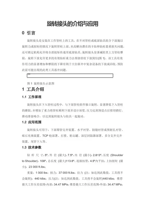
此前可能出现的此类工具落井问题。
静态轴承拉力(最大):240 klbs;静态轴承压力(最大):200 klbs;旋转速度(连续):≤40 r/min;旋转速度(间歇):60 r/min;剪切销钉值(平均):±1.72 MPa;剪切销钉数量(最大):12 个;使用标准黄铜螺钉转换压力(最大):±20.68 MPa;工作压力(最大):75%剪切力。
1.4 基地实验旋转接头在试验基地的水平井进行,通过井口组合7″尾管和旋转接头,模拟海上平台下7″尾管工艺流程,旨在检验旋转接头能否有效减小下套管的难度,有效传递钻杆钻压,以及提高裸眼段水平井下套管的成功率,从而解决水平井下套管磨阻大,钻杆钻压传递不完全,致使套管不能完全下入到预定完井深度的情况;另外,通过解锁、锁定工具锁定装置开关,验证工具锁定装置是否稳定、可靠,在锁定后可实现尾管挂旋转脱手。
1.4.1 地面测试钻具组合:十字浮鞋+7″尾管(500 m) +变扣(BTC*410) +球座(411*410)+5″旋转接头+ 5″钻杆;接旋转接头后,做地面测试。
旋转接头下接头打备钳,旋转接头连短钻杆,接顶驱,开转速10 r/min,工具运行正常,无憋扭现象。
1.4.2 中途测试在1 200 m以后进入第二造斜段,实测井斜达70°,因此在1 200 m至井底,每隔100 m分别测试管柱在旋转和非旋转状态下的上提下放悬重,考察在大斜度井段,旋转接头在增加钻具悬重方面的效果,借以判定旋转接头对于在复杂井段下入尾管是否能起到帮助,试验流体介质为清水[1-2]。
通过测试数据得出如下结论:旋转状态下管柱下放悬重大于静止状态下管柱下放悬重,在工具允许范围内,转速越高旋转下放悬重增加较静止下放悬重增加更明显。
旋转接头能明显降低其上方管柱摩阻,更多钻柱有效重力传递使得尾管下放更容易。
1.4.3 井底测试(1)悬重对比测试。
工具下钻至井底,探底深度1 783.64 m,测试静止和不同转速下管柱上提下放悬重,可得出旋转状态下管柱下放悬重大于静止状态下管柱下放悬重,更多钻柱有效重力传递至管柱下方。

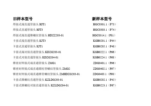
旧样本型号新样本型号焊接式端直通管接头HJT1 HGC0301.1(P73)焊接式直通管接头HJT3 HGC0303.1(P74)焊接式端直通锥螺纹管接头HDZZ203-01 HGC0314.1(P81)卡套式端直通管接头KJT3 KGB0201.1(P44)卡套式直通管接头KJT1 KGB0205.1(P48)卡套式端对接直通管接头KDZG203-01 KGB0222.1(P66)卡套式对接直通管接头KDZG204-01 KGB0224.1(P68)锥密封焊接式端直通管接头ZMG1 ZDG0401.1(P96)锥密封焊接式端直通圆柱管螺纹管接头ZMG2 ZDG0402.1(P97)锥密封焊接式端直通锥管螺纹管接头ZMHDZG203-01 ZDG0403.1(P98)卡套式锥螺纹直通管接头KZLDG203-01 KGB0202.1(P45)卡套式锥螺纹对接直通管接头KZLDG204-01 KGB0223.1(P67)扩口式端直通管接头KDTJT204-01 KGA0101.1(P18)扩口式锥螺纹直通管接头KZLWGJ204-01 KGA0102.1(P19)铜管用管接头GJT639 RGF0603.1(P126)铜管用直通管接头TJT634 RGF0607.1(P127)铜管用直角管接头JJT635 RGF0605.1(P127)钢管用螺纹连接三通接头ST8.5.4 ST8.5.4(P305)钢管用螺纹连接异径三通接头YST8.5.5 YST8.5.5(P305)钢管用螺纹连接弯头WT8.5.6 WT8.5.6(P306)钢管用螺纹连接外接头WT8.5.7 WT8.5.7(P306)钢管用螺纹连接内接头NJT8.5.8 NJT8.5.8(P307)钢管用螺纹连接内外接头NWJT8.5.9 NWJT8.5.9(P307)钢管用螺纹连接分管接头体FJT8.5.12 FJT8.5.12(P310)钢管用螺纹连接活接头HJT638 HJT638(P310)钢管用插入焊接式45°接头JT8.5.13 CGE0510.1(P120)钢管用插入焊接式变径接头BJT8.5.31 CGE0511.1(P121)钢管用插入焊接式接头JT8.5钢管用插入焊接式三通RST8.5.36 CGE0509.1(P120)钢管用插入焊接式弯头RWT8.5.37 CGE0501.1(P113)钢管用插入焊接式直通接头ZJT8.5.58 CGE0506.1(P118)钢管用插入焊接式变径直通接头BZT8.5.59 CGE0507.1(P118)钢管用插入焊接式变径接头RBJT8.5.61 CGE0505.1(P116)钢管用插入焊接式活接头RHT633 CGE0512.1(P121)钢管用插入焊接式高压法兰GFL631 CGE0513.1(P122)钢管用插入焊接式终端法兰ZFL826 CGE0514.1(P122)焊接式管接头SJT825 HGC0315.1(P82)焊接式管接头SJT8.27 HGC0322.1-1(P88)焊接式管接头SJT8.28 HGC0322.1-2(P88)带阀单向阀接头DFT636 DFT636(P317)带阀双向逆止阀接头SFT643 SFT643(P317)高压胶管总成GJG642 PGJ1201.1(P152)等径直角螺纹接头DJJT8.5.56 DJJT8.5.56 (P 313)等径直角螺纹长接头DCJT8.5.57 DCJT8.5.57 (P 313) 双通衬板SB8.5.64 SB8.5.64(P 314)直角法兰TFL8.5.65 TFL8.5.65(P 314)螺塞ZLS203 LGM2001.1(P 257) 旋转接头XJT637 XJT637(P318)分配器罩DWQZ828分配器罩DVQZ829分配器支架QJ8.5.47 QJ8.5.47 (P315)支架ZJ8.5.48 ZJ8.5.48 (P316)支架QJ8.5.43 QJ8.5.43(P316)管夹和管托架GJ811.1、GJ811.2、GJ811.3、GJ811.4 DGJ2201.1、D GJ2201.2、DGJ2201.3、DGJ2201.4(P269) U型螺栓US820 UXG2801.1 (P325)JG-焊接头、JGM-焊接头,带螺母ZTK1101.1焊接头、ZTK1101.2焊接头,带螺母(P148) DZT-端直通接头LGT2801.1 (P325)DZTN/DZTV-端直通管接头(公制螺纹、UNF螺纹)LGT2803.1(P327)BDT-变径端直通接头BDZ-变径端直通接头LGT2802.1 (P326)KDT-可调式端直通接头LGT2807.1(P331)KETM/KETA可调式端直通接头LGT2827.1(P349)KDZ-可调式端直角接头ZGD0416.1(P108)KZ-可调式端直角接头LGT2820.1(P343)STQ-三通管接头LGT2821.1(P344)ZTH-直通焊接接头ZGD0409.1(P103)ZTG-直通管接头ZGD0404.1(P99)ZJG-直角管接头ZGD0410.1(P103)STG-三通管接头ZGD0411.1(P104)FTG-四通管接头ZGD0419.1(P111)ZGB-直通隔壁管接头ZGD0413.1(P105)ZJGB-直角隔壁管接头ZGD0412.1(P105)ZJ-焊接头、DJ-焊接头,带螺母ZTK1103.1、ZTK1104.1(P150) JJT-铰接式接头LGT2817.1(P341)JST-铰接式三通管接头ZGD0418.1(P110)BJT-变径接头体BJT-变径接头体DT-堵头管路测试点接头KSE、HSC CGY2754.1、CGY2755.1(P297) FL-法兰FL(P211)FLJ-法兰接头FLJ(P211)FLM-盲孔法兰接头FLM(P211)FLJ/FLK-法兰接头-PN10-64(bar)FLJ/FLK(P212)FLJ/FLK-法兰接头-PN160(bar)FLJ/FLK(P213)FLJ/FLK-法兰接头-PN250(bar)FLJ/FLK(P214)FLJ/FLK-法兰接头-PN315(bar)FLJ/FLK(P215)FLJ/FLK-法兰接头-PN400(bar)FLJ/FLK(P216)FLJ/FLK-法兰接头-PN500(bar)FLJ/FLK(P217)BHG-变径焊接管BHG(P201)SF-三通法兰接头SF(P218)ZFL-直角法兰接头ZFL(P219)AFLJ/AFLK法兰接头AFLJ/AFLK(P220) DKF-对开法兰DKF(P221)QFL-全法兰QFL(P221)AFLJ-法兰接头AFLJ(P221)AFLK-法兰接头AFLK(P221)AFLM-盲孔法兰接头AFLM(P221)AFKM-盲孔法兰接头AFKM(P222)AFLJ/AFLK法兰接头(BSP内螺纹连接)AFLJ/AFLK(P223)FLA/FL-FLJX焊接法兰接头FLA/FL-FLJX(P224) SAFA/SAF-FLJX焊接法兰接头SAFA/SAF-FLJX(P225) SAFA/SAF-FLJX焊接法兰接头SAFA/SAF-FLJX(P226) BHM-24°锥FLJX法兰接头BHM-24°锥FLJX(P227)BHM-FLJX直角焊接法兰接头BHM-FLJX(P228)BHMW -24°锥FLJX直角法兰BHMW -24°锥FLJX(P229) BHMW -24°锥FLJX直角对开法兰接头BHMW -24°锥FLJX(P230) STF-FLJX三通法兰接头STF-FLJX(P231)旋转接头总成(P232)DJL-旋转接头DJL(P233)XJT/XZT-旋转接头XJT/XZT(P234)EFT-旋转接头EFT(P235)EDA-旋转接头EDA(P236)EDN-旋转接头EDN(P237)END-旋转接头END(P238)EDJ-旋转接头EDJ(P239)EDQO/EDA旋转接头EDQO/EDA(P240)WT-弯头GWJ1601.1(P197)腰形法兰接头-YFJT(3000Psi)YFJT(3000Psi)(P241) 腰形法兰接头-YFJT(6000Psi)YFJT(6000Psi)(P242) 腰形法兰接头-YFJ(3000Psi)YFJ(3000Psi)(P243) 腰形法兰接头-YFJ(6000Psi)YFJ(6000Psi)(P244) 方形法兰接头-FFJ FFJ(P245)方形法兰接头-FFJ FFJ(P246)快速接头-HRS1系列HRS1(P283)快速接头-HRS2系列HRS2(P286)快速接头-HRS3系列HRS3(P289)快速接头-HRS4系列HRS4(P292)轻型管夹(P270- P273)轻型叠加式管夹(P274)重型管夹(P275- P278) 重型叠加式管夹(P279)双联管夹(P280)。
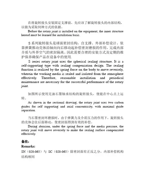
在将旋转接头安装固定支撑前,先应该了解旋转接头的内部结构,以做为采取何种方式的依据。
Before the rotary joint is installed on the equipment, the inner structure hereof must be learned for installation basis.S系列旋转接头是球面密封结构,自支撑、外部补偿设计。
依靠弹簧推动壳体沿轴向向后移动起补偿密封磨损的作用,完成内部介质与外界空气的密封隔离。
因此需要合理的安装方式及定期的维护保养确保产品在设备中的使用.S series rotary joint uses the spherical sealing structure. It is a self-supporting type with sealing compensation design. The sealing function is realized by the spring force on the body to move reversely, wherein the working media is sealed and isolated from the atmosphere effectively. Therefore, reasonable installation and periodical maintenance are necessary for the successful performance of the rotary joint.如图所示使用无油石墨轴承结构的旋转接头,使能在中心点上运转。
As shown in the sectional drawing, the rotary joint uses two carbon guides for self supporting and axial concentricity, with maximal guide separation.当石墨密封环磨损时,由于弹簧力及介质压力的作用下,旋转接头的壳体会往后面移动,使密封面得到有效的补偿。
SL450A ROTARY SWIVEL OPERATION MANUALSL450A-SMGoldenman Petroleum Equipment Co., Ltd Add:7/F, Wanda International Mansion, 67 Fuqian Street , Dongying China Tel:+0086-546-8058779 E-mail:********************CONTENTSI.Technical specifications (2)II.Structure instructions (2)III.Installation (3)IV.Operation (4)V.Lubrication (4)VI. Replacement of Packing Device (4)VII.Maintenance (5)VIII.Inspection and Debuggingent (6)IX.Packing and Shipping (7)X.Recommended Spares List (8)Please read the following operation manual before installing and operating the Swivel. It is necessary to confirm its maximum static loading for operation.The design and operation temperature for the product is -20°C(-4°F). It is necessary to inform lowest working temp when order the product.Regularly conduct NDT on main bearing parts (housing, central pipe, bail and bail pin).I. Technical Specification1. Max. Static Load 4500kN2. Max. RPM 300r/min3. Max. Working Pressure 35MPa4. Central Pipe ID. Ø75mm5. Sub connection 65/8 REG L.H.6. Gooseneck connection 4 LP API Std5B7. Air motor model FMS208. Air pressure 0.7-0.9MPa9. Air consumption 20m3/min10. Spinning speed 92rpm11. Brake torque 2940N.m12. Weight 3310kgII. Structure InstructionsSee Fig.1, SL450A rotary swivel consists of rotary part, fixed part, support part, sealing part and spinning part. Rotary part is composed of central pipe(14) and sub(24). Fixed part includes housing(15), upper cover(2), lower cover(18), gooseneck(10), bail(25) and bail pin (7). Support part consists of main bearing (16), guide bearing (12), and lower guide bearing (20). Seal part includes packing device and upper and lower seal rings. Spinning part covers air motor, air control clutch.Central pipe supports whole weight of drill string and inner mud pressure. Its connection thread with sub and the connection thread of sub and kelly meet API Spec 7-1 and 7-2 requirements.Central pipe is a kind of hollow part. Its upper end connects with packing device (Fig.1),its lower end connects with sub, and its middle part sits on the main bearing with two guide bearings centralize it, among which the upper guide bearing also has the function to avoid central pipe going up. Rubber umbrella (4) on top of the central pipe prevents mud from entering into swivel body.Bail which connects housing via two bail pins is to hang the swivel on the hook. Housing is a support part and is a oil pool for lubricating and cooling main bearings and guide bearings. On its two ends are top cover and bottom cover, on the external size is fitted with buffer (9) to avoid elevator ring impacting housing. Under the top cover is equipped with guide bearing and two oil seals(8). Those two seal rings should be installed in opposite directions, which will prevent oil leaking and mud entering. In top cover there is a thread hole fitted with an oil scale with relief valve function. When air pressure inside housing is higher than outside, the valve will auto open and discharge air. The gooseneck with a thread hole in the top is fixed on the top cover flange. The thread hole is designed for well logging. In drilling process, the hole is sealed with a plug (1) to avoid mud spilling. One end of gooseneck is connected with packing device, the other end is to connect with rotary hose via inner joint (API Std. 5B). Inside the lower cove is fitted with lower guide bearing with three oil seals (21).The packing device connects with the central pipe and the gooseneck pipe, which forms passage for drilling fluid. The packing device is an important part for sealing high pressure mud. It features self-sealing and quick disassembling structure. When wash pipe and packings are worn and needed to be replaced, only need to screw off the upper and lower nuts, then you can take out the whole device from one side, no need to disassemble gooseneck or rotary swivel. Simple, convenient, and can replace any time.Power reducer assembly (11) is secured with bolts and nuts on the upper plane of lower flange of top cover (2). It is an important part for spinning. Spinning is realized by control air valve. Look down at central pipe, clockwise rotation is called forward rotation and anti-clockwise rotation is reverse rotation.III. InstallationRefer to Fig.2 for installation of the spinner. Main control valve (8, left) controls the swivel’s spinning working and its stop. Reverse control valve is to invert the swivel’s rotation. Care should be taken to shut off the main air-in valve (20) when need to change rotation direction of the spinner.IV. OperationLoad test and dynamic pressure test for a new swivel have been conducted before leaving the manufacturing plant, and there is no oil in the swivel housing. So before use, must do the following.1. Unscrew and remove the oil scale, fill with lubricate L-CKC150 (to max. scale), and be sure the oil is clean.2. Inspect the central pipe. Rotate the pipe by a person with a one-meter long Chain tongs. The central pipe should turn evenly.3. Lubricate all grease fittings with gun.4. Check glands of upper and lower packing box (Fig.3, No.1 and No.10), gooseneck union nut (Fig.1,No.10) and sub (Fig.1, No.24) for tight. To ensure good connection and no damage on thread, it is necessary to screw off the sub and apply with thread grease, and tighten with rotary tong.5. Check all air line connections for correct and ensure unobstructed air flow.6. Air filter (Fig.2-19) should be fitted vertically.7. Never allow air motor to run idly.8. According to fields operation experience, new swivel should be used for shallow well, then to deep well, which is good for service life of the swivel.V. Lubrication1. Inspect oil level in the housing of the swivel every shift to see if oil level is higher than minimum limit(never allow oil being le. Replace lubrication oil every 2 months or every 200 hours for new and repaired swivels. Before injecting clean L-CKC150(winter), L-CKC220(summer), flush away dirty oil.2. Lubricate bail pins, packing device and oil seals inside supporting frame with lithium based grease No.1 (winter),or No.2 (summer). Once every shift. Packing must be lubricated when no pump pressure, so the grease can squeeze into every corner of packing and lubricate wash pipe and packing perfectly.3. Check oil level height inside lubricator. The lubricator should be injected with L-AN15 machine oil.VI. Replacement of Packing Device1. Disassemble (Refer to Fig.3)Hammer the nut (LH)(1) until it loose and flush wash pipe(6), then push out packing device from one side of the supporting frame.Separate lower packing box (12) from wash pipe, remove grease fitting (7), take out lower lantern ring (15), spacer rings (13,14), packings (4) and O-rings (9) from lower packing box.Remove stop ring from top side of wash pipe. And take out wash pipe, lantern ring (3), packing and O-ring.2.Inspection2.1 Clean all parts thoroughly.2.2 Check wear and tear. Replace worn and damaged parts.3.InstallationReassemble qualified and replaced parts.3.1Install packings and upper lantern ring coated with grease into upper packing box, and screw on nuts.3.2Put splined end of wash pipe through and install retainer ring.3.3Screw the nut on lower packing box. Put grease-coated packings, spacer ring, and lower lantern ring into lower packing box in proper order.3.4Put non-splined end of wash pipe through into packing carefully.3.5Put in the O ring and grease fitting.3.6Insert packing device into swivel and tighten upper and lower nuts.VII. Maintenance1. Disassemble as per the following steps. Refer to Fig.1.1.1 It is recommended to unscrew the saver sub on end of stem prior to demounting the swivel from rig.1.2 Hold straight the swivel while dismantling.1.3 Screw out plug (27) and plug (28) and drain oil.1.4 Dismount the reducer assembly (11).1.5 Refer to Section V Replacement of Packing Device for demounting the packing device.1.6 Remove rubber umbrella (4) from top end of central pipe.1.7 Dismantle gooseneck (10) and upper cover(2).1.8 Remove adjustment shims.1.9 Dismantle central pipe assembly (including central pipe, upper seat ring of mainbearing, inner rings of upper and lower guide bearings, and upper and lower bushings.)1.10 Take out main bearing carrier, lower seat ring and rollers from housing.1.10 Remove gland (18), tap the outer ring of lower guide bearing (20) and take it out from lower cover, then remove gland on the lower cover. So it is available to take out two oil seal rings and space ring from lower cover. Then remove grease fitting and O seal ring.2. Check and replace parts.2.1It is recommended to replace with new oil seals and O-rings when inspecting the swivel or replacing parts.2.2Check all bearing rollers and seats for broken, worn, corrosion and crack, especially for main bearing, if any defect occurs replace right away, to ensure reliable working performance. Upper seat and lower seat of the main bearing can not be interchanged, as upper seat is transition fitted with central pipe. For dismantling, only need to knock its seat off central pipe. If necessary, heat it to 65-100℃is favorable.3. Reassemble3.1Apply enough grease on lips of two oil seals and then fit into upper cover. Remember the installation of two oil seals should be on the contrary, and separated by spacer ring for lubrication. Secure with stop ring and tap guide bearing (12) into upper cover.3.2Tap out-ring of lower guide bearing (20) into lower cover and fit lower cover into housing.3.3 Set assembled housing upright on the supporter and put the lower ring of main bearing, rollers and holder into the housing.3.4 Put central pipe assembly into the housing.3.5 Turn central pipe assembly slightly to ensure the firm of main bearing.3.6 Install the assembled upper cover to the housing.3.7 Turn the central pipe assembly again to see if all the bearings is set firmly.3.8 Check the clearance between the bottom face of upper cover flange and upper face of housing. Remove the lower cover and put enough adjusting shims (16) to ensure the axial clearance within range 0.05mm~0.25mm.3.9 Enclose the upper cover to the housing. And tighten the screw bolt.3.10 Install rubber umbrella, gooseneck, packing device and joint (sub).3.11 Fix the grease fittings and screw in plugs. Then fill with oil and that will be ok for use.VIII. Inspection and DebuggingInspection and debugging is important in the course of assembly, which will affectservice life of parts. It is recommended to inspect and debug the swivel as per the following procedure.1. The clearance between end faces of upper seat ring of main bearing and central pipe must not be more than 0.03mm.2. Adjusting shims between upper cover and housing are for adjusting the axial clearance of upper guide bearing (12); the clearance should be within range 0.05~0.25mm.3. Inspect the following radial run-out with micrometer.3.1 Inspect upper cover hole as per Fig.4. Radial run out should not be over 0.20mm.3.2 Inspect gooseneck as per Fig. 5. Radial run out should not be over 0.30mm.3.3 Inspect mud pipe as per Fig. 6. Radial run out should not be over 0.30mm.If the radial run-out measured is more than the above range, you should adjust radial run-out of upper cover and gooseneck by releasing upper and lower packing box glands, tapping wash pipe and changing the tightening degree of bolts. Ensure radial run-out is within the specified range, and packing device working under best condition.3.4 Reducer assembly (Fig.7)3.4.1 When to install round nut, adjust bearing to its suitable tightness (Gear can turn freely by hand), then secure.3.4.2 Check clearance between internal and external friction pieces (18,25), keep it in the range of 0.5mm~0.8mm, adjust with shims.3.5 Contact point of gear ring of central pipe (Fig.1, 13) with gear shaft (Fig.7, 15) along depth of tooth should not be less than 40%, along length of tooth not less than 60%.3.6 Connect well air motor, transmission system and air control system.3.6.1 Check air line connection if correct.3.6.2 Check air control console if smooth. Rotation in forward and reverse meets requirements.3.6.3 One-way friction clutch engages normally.IX. Packing and Shipping1. Fix the swivel evenly on the supporter. Air directional valve and vent hole in the air motor should be wrapped with plastic cloth or insert with wood plug. Sub under central pipe should be fitted with a screw protector. Inner joint in the gooseneck should be fitted with protective cap.2. Use a lifting device when move and install the swivel, do not tow it directing on the ground.3. When the swivel is idle for a long time, keep it in a dry and ventilated place. Prior to storage, clean up oil and sediment inside the housing of the swivel, and apply anti-rust oil on threads, bearings, and exposed surface.X. Recommended Spare Parts ListNo. Part No.Description Qty.1RS78.120.00Packing device 12RS78.120-04Packing 103RS78.120-07Snap ring 14RS78.120-06Wash pipe 15RS78.100-09Bail pin 26RS78.100-07Upper bushing 17RS78.100-18Lowe bushing 18JB/ZQ4224O-ring 120*5.759JB/ZQ4224O-ring 135*5.7310JB/ZQ4224O-ring 560*8.6111JB/ZQ4224O-ring 560*3.1112HG-692-67Oil seal SD220*260*18213HG-692-67Oil seal SD250*290*18314RS78.100-06Rubber umbrella 115RS78.310-24Pinion 116Bearing 94754 Q4117RS78.310-22External friction pieceⅠ118RS78.310-21External friction piece Ⅱ119RS78.310-20External friction piece Ⅲ120RS78.310-18External friction piece Ⅳ121RS78.310-17External friction piece Ⅴ122RS78.310-23Internal friction piece Ⅰ223RS78.310-19Internal friction piece Ⅱ224RS78.310-16Internal friction piece Ⅲ2Parts list for Figure 1:No.Part No.Description Qty.No.Part No.Description Qty.1RS76.100-02Plug NPT2116Bearing 94754 Q41 2RS78.300-04Upper cover 117JB/ZQ4224O-ring 560*8.61 3RS78.120.00Packing device 118RS78.100-13Lower cover1 4RS78.100-06Rubber umbrella 119RS78.100-23Lantern ring 1 5HG4-692-67Oil seal D220*260*18220GB/T283Bearing NU104816RS78.100-07Upper bushing121HG4-692-67Oil sealSD250*290*1837RS78.100-09Bail pin222RS78.100-18Lower bushing 18JB/T7940.1Grease fittingM10*1323RS78.100-15Gland19RS78.110.00Cushion 124RS76.100-16Sub 1 10RS78.100-02Gooseneck 125RS78.100-01Bail 1 11RS78.310.00Reducer assy.126RS78.320.00Oil scale 1 12GB/T297Bearing 32040X2127JB/ZQ4446Plug R11 13RS78.300-02Gear ring128JB/ZQ4450Plug M12*1.251 14RS78.300-05Central pipe129JB982Washer 121 15RS78.300-03Housing 1Parts list for Figure 2:No.Part No.Description Qty.No.Part No.Description Qty. 105-03Goose neck 1No.Part No.Description Qty.2XSL160.2C-19Transition jointM39*2-Rc11/2113GB/T3287Reducing jointG11/2-G11305-05Transition jointM52*2-Rc11/2114GB/T3287Inner joint R11405.03.00Hose with joint25*20000115GB/T3287Union jointG11/225Hose 38I*20m 116GB/T3287Inner joint R11/2 4 6A01.5200.000Hose 10*20m 21714.09.01-04A Angle joint 3 705-07Transition joint M18*1.511805-04Four-way joint1 8QF501A Air valve Rc1/4219QSL-40Filter G11/21 9A01.5200.000Hose 10*6m 320Q11F-16Ball valve G11/2 1 10A01.5000-004Joint 321QIU-40Lubricator G11/2 11105-06Transition jointM52*2-R11Fig.1 Outline of SwivelFig.2 Installation of SL450A Swivel (recommended)No.Part No.Description Qty. remarks1RS78.120-01Upper packing box gland 12RS78.120-07Snap ring 13RS78.120-03Upper seal gland 14RS78.120-04Packing55RS78.120-02Upper packing box 16RS78.120-06Wash pipe17JB/T7940.1Grease fitting M10*118GB/T75Screw M10*1219JB/ZQ4224O seal ring 120*5.7110RS78.120-13Lower packing box gland 111RS78.120-12Lowe seal gland 112RS78.120-10Lower packing box 113RS78.120-11Spacer ring Ⅱ214RS78.120-09Spacer ring Ⅰ115RS78.120-08Lower bush ring 116RS78.120-05Upper bush ring 117JB/ZQ4224O seal ring 135*5.71Fig.4 Inspection and Adjustment for AssemblyFig.5 Inspection and Adjustment for AssemblyFig.6 Inspection and Adjustment for AssemblyParts list for Figure 7:No.Part No.Description Qty.No.Part No.Description Qty. 1FMS20Air motor116RS78.310-15Spring10 2Bearing NU207117GB/T276Bearing 60091 3RS78.310-01Gear118RS78.310-16Friction piece III24GB/T292Bearing 7010C119RS78.310-17External frictionpiece Ⅴ15RS78.310-03Spacer plate120RS78.310-18External frictionpieceⅣ16GB/T301Bearing 51120121RS78.310-19Internal frictionpiece Ⅱ27RS78.310-04Gasket122RS78.310-20External frictionpiece Ⅲ18RS78.310-25Shims1组23RS78.310-21External frictionpiece Ⅱ19GB/T119.1Pin 12n6*32224RS78.310-23External frictionpieceⅠ110GB/T301Bearing 51118125RS78.310-22Internal frictionpieceⅠ111JB/ZQ4224O-ring 175*8.6126JB/ZQ4224O-ring 16*2.41 12JB/ZQ4224O-ring 110*5.7127RS78.310-24Pinion1 13JB/ZQ4224O-ring 180*3.1128A01.5200.00Hose 10*500114GB/T283BearingNU2210M129K24JQ.L40.00Directional valve115RS78.310-12Gear shaft13005.01.50.00I Hose jointFig.7 Power Reducer Assembly。
页码
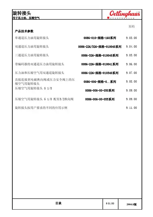
产品技术参数
单通道压力油用旋转接头 0086-010-规格-160系列
9.03.00
双通道压力油用旋转接头 0086-226/326-规格-010040系列 9.04.00 三通道压力油用旋转接头
0086-326-规格-010040系列 9.05.00 带编码器的双通道压力油用旋转接头 0086-226-规格-010041系列 9.06.00 压力油和压缩空气用双通道旋转接头 0086-226-规格-010340系列 9.07.00 直接连接到电磁换向阀或压力安全阀上的压缩空气用旋转接头 0086-006-规格-0..系列 9.08.00 压缩空气用旋转接头 G 1/8
0086-006-00-050系列 9.09.00 压缩空气用旋转接头 G 1/8 配有3/2换向阀 0086-006-00-055系列
9.09.00 旋转接头按用户要求的不同的应用示例 9.11.00
旋转接头
用于压力油,压缩空气
以下是随旋转接头一起供货:
M35x1.5 用于A1和 G1A 用于A:系列0086-006-03-000000
旋转接头 G1/8带3位2通阀控制最大压力= 8 bar。
液压注意 – 用户方责任 错误或不当地选择或使用本样本或有关资料阐述的产品,可能会导致人生伤亡及财产损失! 本样本以及其它由派克汉尼汾公司及其子公司、销售公司与授权分销商所提供的资料,仅供用户专业技术人员在对产品和系统的选型进行深入调查考证时参考。
用户应全面分析自身设备的运行工况、适用的工业标准,并仔细查阅现行的样本,以详细地了解产品及系统的相关信息,通过自己的分析和试验,对产品及系统的独立的最终选择负责,确保能满足自身设备的所有性能、耐用性、维修型、安全性以及预警功能等要求。
对于派克或其子公司或授权分销商而言,应负责按用户提供的技术资料和规范,选择和提供适当的元件或系统,而用户则应负责确定这些技术资料和规范对其设备的所有运行工况和能合理预见的使用工况是否充分和准确。
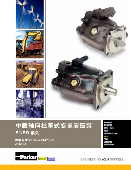
目录目录页次概述 1 订货代号 2 技术参数 4 变量控制器 5 控制选项 “C”, 压力限定(恒压)变量控制器 5 控制选项 “L”, 负载传感及压力限定变量控制器 6 控制选项 “AM”, 带遥控口的标准型先导式压力限定变量控制器 7 控制选项 “AN”, 带ISO 4401 NG06先导阀安装界面的先导式压力限定变量控制器 8 控制选项 “AE”及“AF”, 带电磁比例调节的先导式压力限定变量控制器 9 控制选项 “AMT”, “ALT”及“LOT”, 带最高压力限定的扭矩限定(恒功率)变量控制器 10 P1性能特性 11典型流量特性 11 典型总效率特性 13 典型轴输入功率特性 15 典型噪声特性 18 典型轴承寿命 20 PD性能特性 22典型流量特性 22 典型总效率特性 24 典型轴输入功率特性 26 典型噪声特性 29 典型轴承寿命 31 安装尺寸 33 P1/PD 018 33 P1/PD 028 36 P1/PD 045 40 P1/PD 060 44 P1/PD 075 49 P1/PD 100 54 P1/PD 140 59 变量控制器安装尺寸 65 可提供的扩展的液压产品 75派克汉尼汾备记派克汉尼汾概述简介, 优点派克汉尼汾简介 • 开式回路用轴向柱塞式变量液压泵 • 中压,连续工作压力280 bar • 高驱动转速型,适用于行走机械; 低噪声型,适用于工业应用 • 静音及高效的控制效能 优点 • 总结构尺寸紧凑 • 低噪声• 流量脉动小,进一步降低噪声• 采用弹性密封,不使用密封垫,从而避免外泄漏的产生• 总效率高,功耗小,减小发热• 采用带无泄漏调节装的简单变量控制器 • 符合SAE 及ISO 标准的安装法兰及油口 • 采用圆锥滚柱轴承,使用寿命长 • 全功率后驱动能力• 后部或侧面油口配置可选• 泄油口的配置对水平安装及驱动轴向上垂直安装均适用• 带有最大及最小排量调节选项 • 具有壳体至吸口单向阀选项,可延长轴封寿命 • 使用、维修方便 脉动容腔技术下列图表所示为侧向油口配置P1/PD 18, 28及45泵采用 “脉动容腔” 技术的效果,脉动容腔可降低泵出口处的压力脉动幅值40-60%,这样,无需增加成本来加装噪声缓冲元件,便可大大降低液压系统的整体噪声,P1系列 PD 系列出口压力p / bar平均压力脉动 / b a rP1 045出口压力脉动2600 rpm 无脉动容腔2600 rpm 带脉动容腔订货代号18 ml, 28 ml, 45ml派克汉尼汾P 类型 01 驱动轴 转向R 5密封材料E 油口配置0 壳体-吸口 单向阀 0 排量调节 018 排量 S 安装法兰 及油口 S 轴封 M 应用范围A 设计系列0 通轴驱动选项 C0控制选项0附加控制选项 00油漆 00修改代号系列 P D * 仅适用于045排量, “S”型安装法兰及油口00 标准型, 无修改M2 按要求修改 代号修改代号 * 适用于028及045排量 ** 仅适用于045排量 代号设计系列 A 现行设计系列5 氟碳橡胶 (FPM) 代号密封材料 A 82-2 SAE A M33x2 M27x2 BSPP 1/4”, 3/8” 101-2 SAE B M42x2 M27x2 BSPP 1/4”, 1/2” 101-2SAE B M48x2M33x2Ø38/25DN51/25BSPP 1/4”, 1/2”B ISO M33x2 M27x2 BSPP 1/4”,3/8”ISO M42x2 M27x2 BSPP 1/4”, 1/2” ISO M48x2M33x2Ø38/25DN51/25BSPP 1/4”, 1/2”代号 018排量 028排量 045排量 安装法兰及油口 安装 法兰 螺纹 油口 辅助 油口 安装 法兰 螺纹 油口 辅助 油口 安装法兰螺纹油口法兰 油口辅助 油口 S 82-2 SAE A SAE 16/12 SAE 4/6 101-2 SAE B SAE 20/12 SAE 4/8 101-2SAE B SAE 24/16Ø38/2561系列SAE 4/10M ISO M33x2 M27x2 M12x1.5 M16x1.5 ISO M42x2 M27x2 M12x1.5 M22x1.5 ISO M48x2M33x2Ø38/25DN51/25M12x1.5M22x1.5代号 018驱动轴 028驱动轴 045驱动轴 01 SAE A 11T 花键SAE B-B 15T 花键 SAE B-B 15T 花键02 SAE 19-1平键Ø0.75” SAE B-B 平键Ø1” SAE B-B 平键Ø1” 08— SAE B 13T 花键 SAE B 13T 花键 04 ISO/DIN 平键, Ø20ISO/DIN 平键, Ø25ISO/DIN 平键, Ø25 06 SAE A 9T 花键— — PD 工业液压用 代号 系列P1 行走机械用 代号 排量 018 18 ml/rev (1.10 in 3/rev) 028 28 ml/rev (1.71 in 3/rev) 045 45 ml/rev (2.75 in 3/rev) 代号 类型 P 开式回路用变量柱塞泵 U*通用 代号应用范围 S 工业液压 (PD) M 行走机械 (P1) R 顺时针 (右转)L 逆时针 (左转)代号 转向 代号 轴封 S 单唇轴封 * 并不具有控制功能,仅在运输时予以防护,详情见第7页的控制说明。
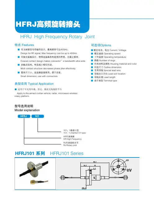
HFRJ高频旋转接头HFRJ High Frequency Rotary Joint■ 专为射频信号传输而设计,最高频率可达40GHz。
Design for RF signal, Max frequency can be up to 40GHz.■ 同轴式接触设计,使得连接器具有超宽的带宽,无截止频率。
Coaxial contact design makes connector’s bandwidth ultra wide.■ 多触点结构,有效减小相位抖动。
Multi contact structure decreases phase jitter effectively.■ 整体尺寸小,连接器接插使用,便于安装。
Small dimension, use with connectors特点 Features■ 额定电流、电压 Current / Voltage ■ 额定速度 Operating speed ■ 工作温度 Operating temperature ■ 路数 Number of rings■ 外壳材料及颜色 Housing material and color ■ 外型尺寸 Outline dimension ■ 专用导线 Special lead wire ■ 导线出口方向 Lead exit location ■ 导线长度 Lead length ■ 端子类型 Terminal type■ 适用于军民用车载、雷达、微波无线旋转平台Apply to the armed civilian vehicle, radar, microwave wireless rotary platform.可选项Options典型应用 Typical Application型号选用说明Model explanation101:1通道01型101: 1 channel O1 type HF代表高频HF:High Frequency RJ代表旋转关节RJ:Rotary jointHFRJ101 系列HFRJ101 Series工业滑环分册HFRJ102系列 SeriesSeriesSeriesHFRJ103系列HFRJ104系列HFRJ105系列工业滑环分册电气技术指标 Electrical dataHFRJ202系列电气技术指标 Electrical data。
Maier旋转接头HHH––B2––––––– HW1, 2, R2 – 450 L––––– HW1 – 500HWA, B, X2 – 500PN 40 DIN 2656 – HWX – HWB– HWA ––3H DN DN mm mmHWHW -450 1 15...25 2, R2 20 + 25 HW X2, A2 32 (100)1, 2, R2, 3 1, 2, R2, 3 15...100 15 (100)PN°C bar min–1-10...220 0,8 (20)-10...300 0,8 (10)-10...250 0,8 (20)-10...300 0,8 (10)-10...230 0,8 (28)-10...300 0,8 (10)-10. 0,8..150 150.000 100.000 150.000 100.000 100.000 50.000 (DN x PN) (DN x PN) (DN x PN) (DN x (DN x PN) (DN x PN) (DN x PN) 15 20 400 25 340 32 420DN min–1*470H H WWX232K–500X R B A1 2 315, 20, 25, 32, 40, 50, 65, 75, 80, 100, 125, 150, 200, 300R L KK4HW B2 32 (100)HW -500 1 32 (100)HW -500X2, A2 32 (100)HW -500 B2 32 (100)HW 1 125...300 A2 100 (300)..230 ..28-10...300 0,8 (10)-10...250 0,8 (20)-10...300 0,8 (10)-10...230 0,8 (28)-10...300 0,8 (10)-10...230 0,8 (28)-10...300 0,8 (10)-10...210 * 0,8...20 *-10...300 0,8 (10).000 x PN) 40 370150.000 100.000 100.000 150.000 (DN x PN) (DN x PN) (DN x PN) (DN x PN) 50 350 65 300 75 250 80 250150.000 150.000 150.000 150.000 150.000 (DN x PN) (DN x PN) (DN x PN) (DN x PN) (DN x PN) 100 200 125 100 150 80 200 60 300 30HWX – HWB – HWA DN 32-100+49 7321 317-239AB CB 06:00A 03:00 09:00 12:00C 01:30 03:00 04:30 06:00 07:30 09:00 10:30 12:005H1 + HW1DN 15 -100DN15 H 115 R 1108050 H 115 L 1108051 H 115 K 1108052 HW 115 R 1108065 HW 115 L 1108066 HW 115 K 110806720 H 120 R 1108130 H 120 L 1108131 H 120 K 1108132 HW 120 R 1108145 HW 120 L 1108146 HW 120 K 1108147 20 G 3/4G 3/4 A 148 122 93 8 88 30 30 36 42 50 8 50 12 8 23 27 2,425 H 125 R 1108210 H 125 L 1108211 H 125 K 1108212 HW 125 R 1108165 HW 125 L 1108166 HW 125 K 1108169 25 G1 G1A 174 143 104 8 97 35 35 40 48 53 8 54 14 9 28 30 3,432 H 132 R 1108350 H 132 L 1108351 H 132 K 1108352 HW 132 R 1108366 HW 132 L 1108367 HW 132 K 1108368 32 G 1 1/4 G 1 1/4 A 203 167 118 10 114 45 45 48 55 62 8 65 16 10 33 41 5,540 H 140 R 1108450 H 140 L 1108451 H 140 K 1108452 HW 140 R 1108465 HW 140 L 1108466 HW 140 K 1108467 38 G 1 1/2 G 1 1/2 A 226 183 124 11 124 52 50 53 65 66 10 70 16 12 36 46 7,150 H 150 R 1108550 H 150 L 1108551 H 150 K 1108552 HW 150 R 1108565 HW 150 L 1108566 HW 150 K 1108567 50 G2 G2A 275 225 146 13 144 66 65 62 80 82 10 81 18 13 43 60 11,365 H 165 R 1108650 H 165 L 1108651 H 165 K 1108652 HW 165 R 1108665 HW 165 L 1108666 HW 165 K 1108667 66 G 2 1/2 G 2 1/2 A 327 264 165 18 182 85 85 80 90 93 10 101 20 15 48 75 21,480 H 180 R 1108750 H 180 L 1108751 H 180 K 1108752 HW 180 R 1108765 HW 180 L 1108766 HW 180 K 1108767 81 G3 G 3 1/2 A 398 320 203 18 220 107 105 100 115 121 12 121 22 20 54 95 37,9100 H 1100 R 1108850 H 1100 L 1108851 H 1100 K 1108852 HW 1100 R 1108865 HW 1100 L 1108866 HW 1100 K 1108867 98G4 G4A 480 383 243 25 260 118 114 115 135 143 12 143 26 22 66 110 62HW ?A B D E F G H ?J ?K ? K G7/h8 L M N O R S T U SW (kg) H13 G 1/2 G 1/2 A 132 109 87 7 80 25 24 31 34 47 6 46 12 7 23 22 1,76H2 + HW2DN 15 -100DN15 H 215 R 1108053 H 215 L 1108054 H 215 K 1108055 HW 215 R 1108068 HW 215 L 1108069 HW 215 K 110807020 H 220 R 1108133 H 220 L 1108134 H 220 K 1108135 HW 220 R 1108148 HW 220 L 1108149 HW 220 K 1108150 20 G 1/2 G 1/4 G 3/4 A 146 122 93 8 88 30 30 36 42 50 8 50 12 8 23 32 27 2,325 H 225 R 1108213 H 225 L 1108214 H 225 K 1108215 HW 225 R 1108167 HW 225 L 1108168 HW 225 K 1108170 25 G 3/4 G 3/8 G1A 172 143 104 8 97 35 35 40 48 53 8 54 14 9 28 35 30 3,232 H 232 R 1108353 H 232 L 1108354 H 232 K 1108355 HW 232 R 1108363 HW 232 L 1108364 HW 232 K 1108365 32 G1 G 1/2 G 1 1/4 A 200 167 118 10 114 45 45 48 55 62 8 65 16 10 33 45 41 5,340 H 240 R 1108453 H 240 L 1108454 H 240 K 1108455 HW 240 R 1108468 HW 240 L 1108469 HW 240 K 1108470 38 G 1 1/4G 3/4 G 1 1/2 A 223 183 124 11 124 52 50 53 65 66 10 70 16 1236 50 46 6,950 H 250 R 1108553 H 250 L 1108554 H 250 K 1108555 HW250 R 1108568 HW 250 L 1108569 HW 250 K 1108570 50 G 1 1/2 G1 G2A 272 225 146 13 144 66 65 62 80 82 10 81 18 13 43 60 60 11,165 H 265 R 1108654 H 265 L 1108655 H 265 K 1108656 HW 265 R 1108668 HW 265 L 1108669 HW 265 K 1108670 66 G2 G 1 1/2 G 2 1/2 A 324 264 165 18 182 85 85 80 90 93 10 101 20 15 48 70 75 21,380 H 280 R 1108753 H 280 L 1108754 H 280 K 1108755 HW 280 R 1108768 HW 280 L 1108769 HW 280 K 1108770 81 G 2 1/2 G 1 1/2 G 3 1/2 A 393 320 203 18 220 107 105 100 115 121 12 121 22 20 54 80 95 37,1100 H 2100 R 1108853 H 2100 L 1108854 H 2100 K 1108855 HW 2100 R 1108868 HW 2100 L 1108869 HW 2100 K 1108870 98 G3 G2 G4A 475 383 243 25 260 118 114 115 135 143 12 143 26 22 66 90 110 61 7HW ?A B C D E F G H ?J ?K ? K G7/h8 L M N O R S T U V SW (kg)H13 G 3/8 G 1/8 G 1/2 A 130 109 87 7 80 25 24 31 34 47 6 46 12 7 23 28 22 1,6HR2 + HWR2DN 15 -100DN15 HR 215 R 1108056 HR 215 L 1108057 HR 215 K 1108058 HWR 215 R 1108071 HWR 215 L 1108072 HWR 215 K 110807320 HR 220 R 1108136 HR 220 L 1108137 HR 220 K 1108138 HWR 220 R 1108151 HWR 220 L 1108152 HWR 220 K 1108153 20 G 1/2 G 1/4 G 3/4 A 146 122 93 8 88 30 30 36 42 50 8 50 12 8 23 12 15 129 27 2,325 HR 225 R 1108219 HR 225 L 1108220 HR 225 K 1108224 HWR 225 R 1108171 HWR 225 L 1108172 HWR 225 K 1108176 25 G 3/4 G 3/8 G1A 172 143 104 8 97 35 35 40 48 53 8 54 14 9 28 16 15 152 30 3,232 HR 232 R 1108359 HR 232 L 1108360 HR 232 K 1108375 HWR 232 R 1108369 HWR 232 L 1108370 HWR 232 K 1108376 32 G1 G 1/2 G 1 1/4 A 200 167 118 10 114 45 45 48 55 62 8 65 16 10 33 20 15 170 41 5,340 HR 240 R 1108459 HR 240 L 1108460 HR 240 K 1108463 HWR 240 R 1108471 HWR 240 L 1108472 HWR 240 K 1108476 38 G 1 1/4 G 3/4 G 1 1/2 A 223 183 124 11 124 52 50 53 65 66 10 70 16 12 36 25 25 198 46 6,950 HR 250 R 1108556 HR 250 L 1108557 HR 250 K 1108560 HWR 250 R 1108571 HWR 250 L 1108572 HWR 250 K 1108573 50 G 1 1/2 G1 G2A 272 225 146 13 144 66 65 62 80 82 10 81 18 13 43 31,8 25 237 60 11,165 HR 265 R 1108657 HR 265 L 1108658 HR 265 K 1108659 HWR 265 R 1108671 HWR 265 L 1108672 HWR 265 K 1108673 66 G2 G 1 1/2 G 2 1/2 A 324 264 165 18 182 85 85 80 90 93 10 101 20 15 48 45 30 284 75 21,380 HR 280 R 1108756 HR 280 L 1108757 HR 280 K 1108761 HWR 280 R 1108771 HWR 280 L 1108772 HWR 280 K 1108773 81 G 2 1/2 G 1 1/2 G 3 1/2 A 393 320 203 18 220 107 105 100 115 121 12 121 22 20 54 45 30 343 95 37,1100 HR 2100 R 1108856 HR 2100 L 1108857 HR 2100 K 1108861 HWR 2100 R 1108871 HWR 2100 L 1108872 HWR 2100 K 1108873 98 G3 G2 G4A 475 383 243 25 260 118 114 115 135 143 12 143 26 22 66 60 40 425 110 61HW ?A B C D E F G H ?J ?K ? K G7/h8 L M N O R S T U ? W G7/e8 X Z SW (kg) 813 G 3/8 G 1/8 G 1/2 A 130 109 87 7 80 25 24 31 34 47 6 46 12 7 23 10 15 117 22 1,6H3DN 25 -40DN25 H 325 R 1108216 H 325 L 1108217 H 325 K 110821832 H 332 R 1108356 H 332 L 1108357 H 332 K 1108358 32 G1 G 1/2 G 1 1/4 A 200 167 118 10 114 45 45 48 55 62 8 69 65 16 10 33 45 41 5,740 H 340 R 1108456 H 340 L 1108457 H 340 K 1108458 38 G 1 1/4 G 3/4 G 1 1/2 A 223 183 124 11 124 52 50 53 65 66 10 7470 16 12 36 50 46 7,3A B C D E F G H ?J ?K ? K G7/h8 L M N O Q R S T U V SW (kg)25 G 3/4 G 3/8 G1A 172 143 104 8 97 35 35 40 48 53 8 64 54 14 9 28 35 30 3,69HW1DN 15 - 25 Serie -450DN152025HW 115 K-450 HW 120 K-450 HW 125 K-450 1108067-450 1108147-450 1108169-450 ?A B E F G H ?J ? K G7/h8 L M N O R ?S T GB (kg) 13 G 1/2 130 107 85 6 80 24 31 34 44 6 52 12 7 12 1,7 20 G 3/4 146 120 91 6 88 30 36 42 49 8 56 12 8 12 2,4 24,5 G1 174 143 104 8 97 35 40 48 53 8 64 12 9 14 3,4HW2 + HWR2DN 20 + 25 Serie -450DN20 HW 220 K-450 1108150-450 HW 220 K-450 1108153-45025 HW 225 K-450 1108170-450 HW 225 K-450 1108176-450 24,5 G 3/4 G 1/2 172 143 104 8 97 35 40 48 53 8 64 12 9 35 1815 152 14 3,2 11A B C E F G H ?J ? K G7/h8 L M N O R ?S T V ? W G7/e8 X Z GB (kg)20 G 1/2 G 3/8 144 120 91 6 88 30 36 42 49 8 56 12 8 32 16 15 127 12 2,3HW1DN 32-100 Serie -500DN3240506580100HW 132 K-500 HW 140 K-500 HW 150 K-500 HW 165 K-500 HW 180 K-500 HW 1100 K-500 1108368-500 1108467-500 1108567-500 1108667-500 1108767-500 1108867-500 ?A B F M DN (kg) 32 G 1 1/4 167 148,5 32 8,5 38 G 1 1/2 183 160,5 40 10,5 50 G2 225 179 50 16 66 G 2 1/2 264 193 65 27 81 G3 320 239,5 80 46 98 G4 383 277 100 7412HW 225 K-74:HW 125 K-24:HW 225 K-27:13HWX2DN 32-100DN32 HWX 232 K 110838540 HWX 240 K 1108485 38 G 1 1/4 G 1 1/4 313 132 204,5 16 159 50 58 75 129 20 151 110 16 15 30 G1 230 16 30,5 16,550 HWX 250 K 1108585 50 G 1 1/2 G 1 1/2 347 153 230 16 181 65 69 87 150 25 160 121 18 16 30 G 1 1/4 267 18 30,5 2265 HWX 265 K 1108685 66 G2 G2 402 178 272 18 218 85 85 103 179 25 180 144 20 18 30 G 1 1/2 307 20 35 3775 HWX 275 K 1108705 67 G 2 1/2 G 2 1/2 535 270 380 18 274 87,29 106 130 267 22,2 210 172 22 25 25 G 1 1/2 416 22 35 7380 HWX 280 K 1108785 80 G 2 1/2 G 2 1/2 540 275 385 18 274 105 106 130 272 30 210 172 22 25 30 G2 426 22 35 73 100 HWX 2100 K 1108885 98 G3 G3 609 305 424 25 302 114 120 145 299 30 240 194 26 26 30 G 2 1/2 472 26 43 92A B C E F G H J ? K G7 / h8 L M N O P R ?S T V W Z GB NT (kg)32 G1 G1 271 120 183 13,5 150 45 55 70 118 15 125 98 1613 25 G 3/4 206 16 23 1214HWB2DN 32-100DN32 HWB 232 K 110840240 HWB 240 K 1108482 38 G 1 1/4 G 1 1/4 313 132 204,5 16 159 50 58 75 129 20 151 110 16 15 28 30 190 16 30,5 16,550 HWB 250 K 1108577 50 G 1 1/2 G 1 1/2 347 153 230 16 181 65 69 87 150 25 160 121 18 16 35 30 225 18 30,5 2265 HWB 265 K 1108677 66 G2 G2 402 178 272 18 218 85 85 103 179 25 180 144 20 18 45 40 260 20 35 3775 HWB 275 K 1108702 67 G 2 1/2 G 2 1/2 535 270 380 18 274 87,29 106 130 267 22,2 210 172 22 25 45 40 372 22 35 7380 HWB 280 K 1108778 80 G 2 1/2 G 2 1/2 540 275 385 18 274 105 106 130 272 30 210 172 22 25 60 40 377 22 35 73 100 HWB 2100 K 1108902 98 G3 G3 609 305 424 25 302 114 120 145 299 30 240 194 26 26 75 50 419 26 43 92A B C E F G H J ? K G7/h8 L M N O P R ?S T ? W G7/e8 X Z GB NT (kg)32 G1 G1 271 120 183 13,5 150 45 55 70 118 15 125 98 16 13 22 30 172 16 23 1215HWA2DN 32-100DN32 HWA 232 K 110839040 HWA 240 K 1108490 38 G 1 1/4 G 1 1/4 313 132 204,5 16 159 50 58 75 129 20 151 110 16 15 28 30 190 16 30,5 16,550 HWA 250 K 1108590 50 G 1 1/2 G 1 1/2 347 153 230 16 181 65 69 87 150 25 160 121 18 16 35 30 225 18 30,5 2265 HWA 265 K 1108690 66 G2 G2 402 178 272 18 218 85 85103 179 25 180 144 20 18 45 40 260 20 35 3775 HWA 275 K 1108710 67 G 2 1/2 G 2 1/2 535 270 380 18 274 87,29 106 130 267 22,2 210 172 22 25 45 40 372 22 35 7380 HWA 280 K 1108790 80 G 2 1/2 G 2 1/2 540 275 385 18 274 105 106 130 272 30 210 172 22 25 60 40 377 22 35 73 100 HWA 2099 K 1108880 98 G3 G3 609 305 424 25 302 114 120 145 299 30 240 194 26 26 75 50 419 26 43 92A B C E F G H J ? K G7/h8 L M N O P R ?S T ? W G7/e8 X Z GB NT (kg)32 G1 G1 271 120 183 13,5 150 45 55 70 118 15 125 98 16 13 22 30 172 16 23 1216HWX2 + HWB2 + HWA2DN 32-100-500DN324050657580100 HWX 2100 K-500 1108885-500 HWB 2100 K-500 1108902-500 HWA 2099 K-500 1108880-500 98 G3 G3 305 269,5 240 80 107HWX 232 K-500 HWX 240 K-500 HWX 250 K-500 HWX 265 K-500 HWX 275 K-500 HWX 280 K-500 1108385-500 1108485-500 1108585-500 1108685-500 1108705-500 1108785-500 HWB 232 K-500 HWB 240 K-500 HWB 250 K-500 HWB 265 K-500 HWB275 K-500 HWB 280 K-500 1108402-500 1108482-500 1108577-500 1108677-500 1108702-500 1108778-500 HWA 232 K-500 HWA 240 K-500 HWA 250 K-500 HWA 265 K-500 HWA 275 K-500 HWA 280 K-500 1108390-500 1108490-500 1108590-500 1108690-500 1108710-500 1108790-500 ?A B C F M P DN (kg) 32 G1 G1 120 161,5 125 25 16 38 G 1 1/4 G 1 1/4 132 168,5 151 32 22 50 G 1 1/2 G 1 1/2 153 182,5 160 40 29 66 G2 G2 178 202 180 50 46,5 67 G 2 1/2 G 2 1/2 270 233 210 65 84,5 80 G 2 1/2 G 2 1/2 275 233 210 65 84,517HW1DN 125-300DN125 HW 1125 K 1104001150 HW 1150 K 1104101 145 DN 150 706 393 440 25 346 180 210 258 413 40 350 40 25 46 245200 HW 1200 K 1104201 195 DN 200 881 498 560 25 420 230 265 320 593 45 400 40 25 46 305300 HW 1300 K 1104401 298 DN 300 1314 700 840 35 595 350 385 486 853 60 700 50 40 58 435A B E F G H ?J ? K G7/h8 L M N O R ?S T SH TA (kg)120 DN 125 653 370 410 20 319 150 183 250 410 35 300 25 20 31 20618HWA2DN 100-300DN100 HWA 2100 K 1108890125 HWA 2125 K 1104002 120 DN 100 DN 100 928 360 415 20 319 150 183 250 410 35 450 300 25 20 88 80 592 31 206150 HWA 2150 K 1104102 145 DN 125 DN 125 1030 394 445 25 346 180 210 258 413 40 502 350 40 25 110 80 635 46 245200 HWA 2200 K 1104202 195 DN 150 DN 150 1286 498 570 25 420 230 265 304 593 45 638 400 40 25 135 100 808 46 305300 HWA 2300 K 1104402 298 DN 250 DN 250 1910 708 84035 595 350 385 486 853 60 977 700 50 40 215 150 1169 58 435A B C E F G H ?J ? K G7/h8 L M N O P R ?S T ? W G7/e8 X Z SH TA (kg)98 DN 80 DN 80 815 328 365 20 268 114 152 210 360 30 388 250 25 20 75 80 528 31 11719。

旋转接头的原理及结构 HEN system office room 【HEN16H-HENS2AHENS8Q8-HENH1688】旋转接头的原理及结构有三个油口和车间管路相连接,分别是A口、B口、和Y口中。
三个油口与旋转接头的外壳是静连接的。
外壳和开卷机或卷取机是保持相对不转动的。
心轴的直径小于外壳的直径,其间隙与一般液压缸的缸筒与活塞之间的间隙相当。
由于安装的原因使旋转接头在旋转过程中会产生摆动,两个轴承用于承受外壳摆动时产生的轴向力,并使心轴与外壳之间保持间隙。
旋转密封的材料为耐磨的复合材料或金属材料,旋转密封安装心轴与外壳之间。
旋转密封能承受高压,通常能达到200bar,材料较硬,密封性能不好。
油封是骨架唇形密封,不能承受过高的压力,通常不能超过3bar,但是其在低压高速情况下有很好的密封性,其作用是封闭来自旋转密封的泄漏油。
泄漏油必须在很低压力的情况下被排回油箱中,以保护油封不被损坏。
在泄漏油管上不能安装过滤器。
旋转接头通过最右端的法兰与涨缩缸把合在一起,旋转接头的油口与液压缸的油口对接。
旋转接头的旋转密封主要有两类,复合材料密封和机械密封。
复合材料密封的密封性能相对要好一些,用在液压缸有中间定位的场合。
使用复合材料密封的旋转接头由于密封本身的尺寸较小,可以使旋转接头制作的更加紧凑小巧。
复合材料密封本身的成本也要比机械密封便宜很多。
复合材料旋转密封由两部份组成,由一个PTFE材质的外环和一个NBR材质的O形圈组合而成。
O形圈起到支承外环的作用,使整个旋转密封更容易安装。
外环与旋转接头的外壳之间滑动。
机械密封在理论上可以实现无接触滑动,可以达到很长的寿命。
机械密封的制作比较复杂,精度要求也比较高,相对较贵。
目前采用机械密封的旋转接头国内还没有生产。
下图是德国GAT公司的产品内部结构示意图。
介质从外壳>部件1>部件3>心轴>液压缸。
机械旋转密封套在心轴上,心轴与旋转接头之间的密封用的是上面提到复合材料旋转密封,当机械旋转密封卡死时,机械旋转密封与心轴之间可以存在相对转动,复合材料旋转密封启着保险作用,机械旋转密封与外壳之间的配合与密封也是通过复合材料旋转密封实现的。
RC系列单作用液压油缸★特有的GR2双重导向环技术能够轻松地吸收偏载,减少磨损,延长油缸寿命。
★外环螺纹、柱塞螺纹和底部安装孔使得定位方便(对多数型号而言)。
★设计为在任何安装位置上使用。
★可拆卸手柄使固定方便(RC-5013,RC-7513和所有95吨型号油缸)。
★高强度合金钢经久耐用。
★高强度复位弹簧。
★烤漆表面耐腐蚀能力更强。
★各型号均包含CR-400快速接头与防尘帽。
★防尘密封圈可减少污染,延长液压缸使用寿命。
RSM&RCS系列单作用薄型液压油缸RSM系列超薄型液压油缸★紧凑扁平设计用于其它液压缸不适用的场合。
★RSM-750/-1000/-1500配有手柄便于搬运。
★安装孔使固定方便。
★所有型号均包含CR-400快速接头与防尘帽,除RSM-50配有AR-400快速接头。
★高质量钢柱塞表面镀硬铬处理。
★沟槽柱塞端面无需鞍座。
★单作用,弹簧回缩。
RCS系列,薄型液压油缸★轻巧紧凑设计用于狭小工作空间。
★烤漆表面增强耐腐蚀能力。
★防尘圈减少污染,延长液压缸使用寿命。
★所有型号均包含CR-400快速接头与防尘帽。
★沟槽柱塞顶部的螺纹孔可用于安装倾斜式鞍座。
★RCS-1002配有手柄便于携带。
★钢柱塞表面镀青铜处理。
★单作用,弹簧回缩。
RCH系列单作用中空柱塞液压油缸★中空柱塞设计既可以用于拉力,又可以用于推力。
★单作用,弹簧回缩。
★对于20吨以上的型号,使用镀镍的浮动中心管增加产品寿命。
★烤漆表面耐腐蚀能力更强。
★外环螺纹使安装方便。
★RCH-120包括AR-630接头,具有1/4NPT油口。
★RCH-121和RCH-1211配有FZ-1630变径接头和AR-630快速接头、其它型号配CR-400接头。
P系列新型钢制手动泵★恩派克新型高压钢制手动泵是棘手工作的首选。
★动力推进把手,增加舒适度,减少疲劳。
★双速操作,可减少操作者劳动强度(除P-39)。
★免排气储油箱,防止溢漏。
★配有手柄,易于提携。
旋转接头介绍
什么叫旋转接头:
旋转接头是将流体介质从静止的管道输入到旋转或往复运动的设备中,再从旋转接头中排出的连接密封装置,简称“旋转接头〞。
旋转接头的组成:
单通路旋转接头-就是一个方向进水
单通
双通-由进水孔〔弯头配长内管〕进入再由出口流出,全过程不泄露
以上介绍全是平面密封〔因为用量太大,也是应用最广泛的〕
旋转接头的类别
平面密封〔机械密封〕
球面密封〔凹凸严密配合密封〕大多用在造纸,印染,〔我也不太专业所以这个就不介绍了〕线密封〔O型圈密封〕大口径旋转接头〔海底输油管道-钢铁大型管道水,用量不大〕
这3种类别是最常见的也是国际都在用的密封方式
旋转接头的应用:
钢铁用量是最大的,连铸机,火红的钢材在运输线上温度太高,就要给运输棍冷却,旋转接头就用在运输棍两端给炉棍内部冷却。
其他行业也根本都是这样使用
要么用旋转接头给辊到冷却,要么通蒸汽或热油给辊道加热,
这是单通使用图
双通使用图
尺寸比照
DN 8 10 15 20 25 32 40 50
2 1/2 3〞4〞
DN 65 80 100。
ENGINEERINGCATALOG2600E n g i n e e r e d f o r P e r f o r m a n c eROTATING UNIONSwater steam air hydraulic hot oil vacuum coolant custom applicationsw w w.d e u b l i n.c o mw w w .d e u b l i n .c o m2Selection Chart for DEUBLIN Rotating UnionsWater & Hot Oil up to 250°F *6-213/8" - 2"557502503,500General Purpose 1 or 2 6 - 103/8" - 2"571502003,500Water Service 1 or 27 - 1021/2"755200250750General Purpose 1 or 2113"857150250500Water Service 1 or 212 - 133/8" - 1"541,8002003,500316 Stainless Steel1143/8"9274,0002002,000Water Service High Pressure 1151/2" - 3/4"221,500250250Water Service Car Wash 1152" - 4"6000150250750Water Service Cartridge Seal 1 or 216 - 195"F127150250750Water Service1 or 2203/4" - 1 1/2"2400150250100Water Service Continuous Casters 1 or 221Steam & Hot Oil up to 450°F * 22-303/8" - 1/2" N Steam 250400750Single Bearing Spherical Seal 1 or 2223/8" - 1/2" N Hot Oil 100450750Single Bearing Spherical Seal 1 or 2223/4" - 2" 9000 Steam 150365400Single Bearing Spherical Seal 1 or 223 - 253/4" - 2" 9000 Hot Oil 100450400Single Bearing Spherical Seal 1 or 223 - 2511/2"HPS Steam 250400400Dual Bearing Spherical Seal 2263/4" - 2"H Steam 150365400Dual Bearing Spherical Seal 1 or 227 - 3021/2" - 5"H Steam 150365180Dual Bearing Spherical Seal 1 or 227 - 303/4" - 2"H Hot Oil 100450400Dual Bearing Spherical Seal 1 or 227 - 3021/2" - 5"H Hot Oil 100450350Dual Bearing Spherical Seal 1 or 227 - 30Air &Hydraulic31-451/8" - 3/8"1005,1102,11151,0002503,500Standard Applications 131 - 321/2"1205,2200 1,0002503,500Standard Applications 131 - 323/4" - 1 1/2"250,355,4521,0002503,500Standard Applications 1331/8" - 3/8"1005,1102,11151,0002503,500In-the-shaft Mounted 1341/4" - 1/2"AP 5,7002001,500High Pressure High Speed1351/4" - 1 1/2"D 6,400120250High Pressure Low Speed or Swivel 1363/8" X 215001502501,500DEU-PLEX Air 2371/2" X 215901502501,500DEU-PLEX Air 2381/2" X 215791,0002501,500DEU-PLEX Hyd Oil2391/4" X 225207502505,000DEU-PLEX Air & Hyd Oil 2403/8" - 1/2" X 41379,14793,600175250Multi Media 4 Pass4411/4" - 1/2"17,213,000250250Low Speed Air & Hyd Oil1421/4" X 1/2"21173,000250250Low Speed Tandem Air & Hyd Oil 2431/4"-1/2"-3/4" X 21690,1790,18903,00025020DEU-PLEX Low Speed 244 - 451/4" X 3/4" X 318903,000250250Triple Passage345Coolant (Wider range of products featured in Coolant Union Catalog)46-513/8"11172,00016020,000Bearingless1463/8"11292,00016020,000Bearingless ("Pop-Off") High Speed 1473/16"11011,50016015,000Standard Applications High Speed 1483/8"11161,00016010,000Standard Applications1491/4" - 3/8"11091,50016020,000Dry-run ("Pop-Off") High Speed 1503/8"9021,00016010,000Dry-run ("Pop-Off")151Unions for Special Applications *52-531/8" - 1"1005,468,9817502503,500Water,Oil Rig,Clutch & Brake 1 to 3521/4" - 3/8"1102,1115,8821502503,500Central Tire Inflation 1 or 252Custom7000 / 71003,0002505,000Around The Shaft53SizeSeriesPagesPassagesDescriptionTemp.Speed PSI °F RPM*Attention! For applications exceeding indicated limits,contact DEUBLIN.Indicate media,size,speed (RPM),pressure,temperature and connection specifications.-Subject to technical and dimensional changes without notice.1-847-689-8600 o r Max.Operating DataSince 1945,Deublin has grown from a small garage shop to theworld’s largest manufacturer of rotating unions.Today,Deublin’sinternational headquarters is located in Waukegan,Illinois,withmanufacturing facilities,sales offices and warehouses located in17countries on four continents.DEMAND CUSTOM UNIONSo r w w w.d e u b l i n.c o m1-847-689-8PROFESSIONAL SERVICE AROUND THE WORLDAt Deublin,our service is as reliable as our products.Given the importance of rotating unions to your equipment’s performance,our products have to be reliable.To provide you local and emergencyOperating DataMaximum Water Pressure Model55-555 750 PSI50barMaximum Water Pressure Model655600 PSI41barMaximum Saturated Steam Pressure (Intermittent)15 PSI 1 barForged BrassOperating DataMaximum Water Pressure 150 PSI 10 bar 1-847-689-8600 o r Seal GuideSilicon Carbide Keyed Rotor SealGasketCarbon Graphite/Silicon Carbide Floating SealViton-O-RingCoil SpringAcross FlatsA1/16"D 1Monoflow Length(3) 11/32"Dia. VentsEq. SpacedJLock-up Approx81-847-689-8600 o r w w w .d e u b l i n .c o m55 & 57 Series Monoflow Union SpecificationsChart InstructionsSelect Union Size and Rotor Thread.Follow this line to opposite page to find Duoflow Elbow Specifications.Add Duoflow Elbow Suffix to the end of the Ordering Number.†Recessed O-Ring in Rotor End in Place of Copper Gasket55-000-00155-147-15157-000-00157-050-0013⁄8"NPT RH 13⁄4"315⁄16"413⁄16"1"5⁄8"3⁄8"7⁄8"211⁄16"55-000-00255-147-15257-000-00257-050-0023⁄8"NPT LH 55-000-00355-147-14957-000-00357-050-0035⁄8"-18 UNF RH 13⁄4"315⁄16"413⁄16"1"5⁄8"3⁄8"7⁄8"21⁄2"55-000-00455-147-15057-000-00457-050-0045⁄8"-18 UNF LH 55-000-09455-147-19257-000-09457-050-094G 3⁄8"(BSP)RH 44.510212326169.522.26355-000-09555-147-19357-000-09557-050-095G 3⁄8"(BSP)LH 155-000-001155-208-113157-000-001157-050-0011⁄2"NPT RH 21⁄4"413⁄16"57⁄8"17⁄16"7⁄8"1⁄2"11⁄8"31⁄2"155-000-002155-208-114157-000-002157-050-0021⁄2"NPT LH 155-000-021155-208-185157-000-021157-050-0213⁄4"-16 UNF RH 21⁄4"411⁄16"53⁄4"15⁄16"3⁄4"1⁄2"11⁄8"31⁄16"155-000-022155-208-229157-000-022157-050-0223⁄4"-16 UNF LH 155-000-151155-208-252157-000-151157-050-151G 1⁄2"(BSP)RH 57.2120148341912.728.678155-000-152155-208-253157-000-152157-050-152G 1⁄2"(BSP)LH 255-000-020255-052-255257-000-020257-050-0203⁄4"NPT RH 27⁄8"59⁄16"63⁄4"17⁄16"7⁄8"11⁄16"11⁄4"41⁄16"255-000-021255-052-256257-000-021257-050-0213⁄4"NPT LH 255-000-003255-052-258257-000-135†257-050-135†1"-14 UNS RH 27⁄8"57⁄16"65⁄8"15⁄16"3⁄4"21⁄32"11⁄4"311⁄16"255-000-027255-052-257257-000-136†257-050-136†1"-14 UNS LH 255-000-284255-052-445257-000-284257-050-284G 3⁄4"(BSP)RH 73138168341917.53294255-000-285255-052-446257-000-285257-050-285G 3⁄4"(BSP)LH 355-000-002355-064-186357-000-002357-050-0021" NPT RH 31⁄4"613⁄16"85⁄16"115⁄16"11⁄8"1"11⁄2"411⁄16"355-000-003355-064-187357-000-003357-050-0031" NPT LH 355-000-019355-064-328357-000-019357-050-01911⁄2"-12 UNF RH 31⁄4"613⁄16"85⁄16"115⁄16"11⁄8"1"11⁄2"41⁄4"355-000-074355-064-329357-000-074357-050-07411⁄2"-12 UNF LH 355-000-222355-064-378357-000-222357-050-222G1" (BSP)RH 75.41662044221.522.238.1108355-000-223355-064-379357-000-223357-050-223G1" (BSP)LH 525-000-001525-097-043527-000-001527-050-00111⁄4"NPT RH 39⁄16"79⁄16"93⁄8"23⁄16"11⁄8"11⁄4"13⁄4"51⁄4"525-000-002525-097-044527-000-002527-050-00211⁄4"NPT LH 525-000-026525-097-095527-000-026527-050-02613⁄4"-12 UN RH 39⁄16"79⁄16"93⁄8"23⁄16"13⁄16"11⁄4"13⁄4"411⁄16"525-000-027525-097-096527-000-027527-050-02713⁄4"-12 UN LH 525-000-054525-097-122527-000-054527-050-054G11⁄4"(BSP)RH 90.5191234542730.244.5119525-000-055525-097-123527-000-055527-050-055G11⁄4"(BSP)LH 555-000-001555-033-154557-000-001557-050-00111⁄2"NPT RH 41⁄4"81⁄2"105⁄16"27⁄16"13⁄16"11⁄2"21⁄8"6"555-000-002555-033-160557-000-002557-050-00211⁄2"NPT LH 555-000-395555-033-399557-000-395557-050-3952"-12 UN RH 41⁄4"87⁄8"1011⁄16"213⁄16"11⁄8"11⁄2"21⁄8"513⁄16"555-000-396555-033-382557-000-396557-050-3962"-12 UN LH 555-000-198555-033-288557-000-198557-050-198G11⁄2"(BSP)RH 10822526871293554147555-000-199555-033-289557-000-199557-050-199G11⁄2"(BSP)LH 655-500-116655-502-116657-000-116657-050-1162" NPT RH 45⁄8"101⁄16"113⁄4"3"11⁄2"17⁄8"21⁄4"7"655-500-117655-502-117657-000-117657-050-1172" NPT LH 127⁄16"655-500-124655-502-124657-000-124657-050-124G2" (BSP)RH 1172462896528.64755164655-500-125655-502-125657-000-125657-050-125G2" (BSP)LHB Port NPTA xRotor ThreadC D 1D 2E FGHJOrdering Number 55 Series All Purpose55 Series E.L.S.57 SeriesE.L.S.57 Series Water Service3⁄8"1⁄2"3⁄4"1"2"11⁄4"11⁄2"xMetric threads and other thread sizes are available.Contact factory for further information.For 2",21⁄2",3",4" and 5" capacity unions refer to pages 11-13 and 16-20.DEUBLIN91-847-689-8600 o r w w w .d e u b l i n .c o mG Rotor HolePipe Supplied By CustomerA1/16"R Pipe Length Into UnionD 2Duoflow Length(3) 11/32"Dia. VentsEq.SpacedJLock-up Approx.H Across FlatsSPipe Ø55 & 57 Series Duoflow Union SpecificationsFixed Supply Pipe DetailRotating Supply Pipe Detail———-030.250"43⁄16"—————1⁄4"11⁄16"13⁄8"1⁄4"2#———-030.250"43⁄16"—————1⁄4"11⁄16"13⁄8"1⁄4"2#-120M6X198.5————————1⁄4"18351⁄4"0.9 Kg -0121⁄8"NPT 43⁄4"-061.375"57⁄16"—————3⁄8"11⁄16"11⁄2"3⁄8"3#-0121⁄8"NPT43⁄4"-061.375"55⁄16"-0611⁄8".371"13⁄16"5"3⁄8"11⁄16"11⁄2"3⁄8"3#.370"-199G 1⁄8"(BSP)117———-471—9.93301273⁄8"18383⁄8"1.4 Kg 9.90-0431⁄4"NPT 51⁄4"-075.500"513⁄16"—————1⁄2"1"13⁄4"1⁄2"5#-0441⁄8"NPT 51⁄8"-026.437"-0431⁄4"NPT 51⁄8"-075.500"513⁄16"-0751⁄4".496"11⁄4"511⁄16"1⁄2"1"13⁄4"1⁄2"5#-0441⁄8"NPT 5"-026.437".495"-368G 1⁄4"(BSP)136.5———-681—12.9531146.51⁄2"26451⁄2" 2.3 Kg -367G 1⁄8"(BSP)132.512.90-0833⁄8"NPT 71⁄16"-163.625"71⁄8"—————3⁄4"11⁄16"25⁄16"1⁄2"8#-0841⁄4"NPT 7"-0833⁄8"NPT 71⁄16"-163.625"71⁄8"-1633⁄8".621"11⁄4"7"3⁄4"11⁄16"25⁄16"1⁄2"8#-0841⁄4"NPT7".619"-255G 3⁄8"(BSP)162—-——-347—15.95311753⁄4"27591⁄2" 3.6 Kg 15.90-0071⁄2"NPT 81⁄8"-104.750"81⁄4"—————1"13⁄8"213⁄16"3⁄4"10#-0071⁄2"NPT81⁄8"-104.750"81⁄4"-1041⁄2".745"11⁄2"83⁄16"1"13⁄8"213⁄16"3⁄4"10#.743"-079G 1⁄2"(BSP)185.5———-237—21.9438201.51"35723⁄4" 4.5 Kg 21.89-0133⁄4"NPT 813⁄16"-263 1.000"91⁄8"—————11⁄4"11⁄2"31⁄16"3⁄4"16#-0361⁄2"NPT 83⁄4"-0133⁄4"NPT 93⁄16"-263 1.000"91⁄2"-1443⁄4"1.000"13⁄4"95⁄16"11⁄4"11⁄2"31⁄16"3⁄4"16#-0361⁄2"NPT91⁄8".998"-221G 3⁄4"(BSP)222———-468—25.914424411⁄4"38783⁄4"7.2 Kg 25.81-0133⁄4"NPT 101⁄4"-263 1.000"105⁄8"—————11⁄4"11⁄2"31⁄16"3⁄4"17#-1831"NPT103⁄8"13⁄4"31⁄2"1"-221G 3⁄4"(BSP)243———-468—25.914425011⁄4"38783⁄4"7.7 Kg25.81RKNPTMNO NPTShpg.Wt.Fixed Supply Pipe Fixed Supply TubeElbow SuffixThread R Elbow Suffix TubeODRotating Supply PipeS RElbowSuffixPipe Size PipeDia.D 2Duoflow LengthThread SpecificationPipe Supplied By CustomerOFor Description See Page 10101-847-689-8600 o r w w w .d e u b l i n .c o mThreaded PipeThe largest threaded supply pipe achieves the maximum flow rates available for a particular size union. Stresses at the pipe thread can cause breakage allowing the pipe to fall into the roll. For this reason pipe lengths longer than 4union lengths (4 x D1) and rotational speeds above 1000RPM should be avoided.Fixed TubeThin wall stainless steel tube silver soldered into the Duoflow elbow produces the strongest, lightest weightassembly.The thinner wall sections allow greater flow rates than the threaded pipe. Maximum flow rates are obtained with the largest tube available for a given size union. Tube length is usually limited to 6 union lengths (6 x D1). Speeds to 3500 RPM are possible.Rotating PipeRotating pipes are fastened internally to rotate with the roll.The Duoflow elbow helps to support the pipe and restrict crosstalk between passages. The pipe must be straight and concentric to the center line to avoid excessive loading of the union. The union must also have a rotor with astraight thread (Example 1"-14 UNS) rather than a tapered pipe thread to assure concentricity. Rotational speeds above 1000 RPM should be avoided.Deublin water service unions can be adapted for Duoflow applications where a single media is circulated through and around the supply pipe. Duoflow elbows are available in 3 styles to accept a variety of different supply systems.The guidelines shown below should be carefully considered. A poorly designed supply system can contribute to premature union failure.Where long pipes or high speeds are required, an adapter should be used to avoid transmitting stresses from heavy pipes, cascading water or vibrations to the union. A typical adapter is illustrated.Customer ShaftAdapter*PilotGasketUnionStationary TubeElbowInletOutletRotorGasket*Carbon Filled TFE Bearing*Rotating Pipe**Supplied by customer.Duoflow Supply Pipe InstallationsR EFPipe Supplied by Customer2" NPTD2D1CCast Iron HousingSupply Pipe(Stationary Shown)Stainless Steel SpringDual Ball BearingsOperating DataVent Supply Pipe(Rotating Shown) Dual Ball BearingsDEUBLIN7/8"31/2"J R D 9"Dia.GAFE DC1/16"7/8"3.312"3.307"Dia.DRJ Type I Type II Type III14181814159910413/16"13/16"13/16"13/16"11/16"11/16"7/8"3/16"3/8"7/8"1/4"2Dia.3.430"3.425"Dia.BJH (Across Flats)1/4"27/8"Dia.4.004"4.002"Pilot Dia.(6) 11/16"Dia. Bolt Holeson a 79/16"DBC1Type I Type II Type III 13171714"14991013/16"13/16"15/16"15/16"13/16"11/16"5/16"D RPipe Length Into UnionE FCGPipe Supplied By CustomerA JH (Across Flats)BNOP 3" NPTT -Dia.SRPipe Length Into UnionFlange O-Ring size 2-353857 Series Specifications857-132 Flanged Rotor DetailType I Monoflow857-128 Quick ConnectRotor DetailType IIDuoflow Fixed PipeType IIIDuoflow Rotating Pipe857-000-1013" NPT RH 71⁄2"133⁄4"37⁄16"17⁄8"27⁄8"4"109⁄16"------50#857-000-1023" NPT LH 857-000-118G3" (BSP) RH 190344834473102244------23 Kg 857-000-119G3" (BSP) LH 857-001-1013" NPT RH 71⁄2"177⁄8"37⁄16"17⁄8"27⁄8"4"93⁄4"511⁄16"2"2"1315⁄16"--55#857-001-1023" NPT LH 857-001-118G3" (BSP) RH 1904518344731022281442"2"351--25 Kg857-001-119G3" (BSP) LH 857-002-1013" NPT RH 71⁄2"177⁄8"37⁄16"17⁄8"27⁄8"4"93⁄4"511⁄16"2"-141⁄4"23⁄4" 2.308"55#857-002-1023" NPT LH 2.302"857-002-118G3" (BSP) RH 1904518344731022281442"-3557058.6225 Kg857-002-119G3" (BSP) LH58.47B Port NPTC Dia.D E F G H J NO NPT P NPTR S TShpg.Wt.Ordering Number ARotor Thread 3"T y p e IT y p e I IT y p e I I I2"2"Operating DataDEUBLIN Exclusive On-The-Machine Repair CartridgeCast Iron HousingCast Iron End Cap (nickel-plated)Supply Pipe (Rotating Shown)Composite BearingVentReplaceable Seal CartridgeReplaceable Rotor SealCarbon Steel RotorHeavy-Duty Dual Ball BearingsA Dia.WB.C.PilotDia.JLock-upJLock-upZR Dia.Lug HoleMonoflow Rotating UnionFlanged O-Ring(supplied by DEUBLIN)for:Model O-Ring Size62002-343 Viton62502-343 Viton63002-353 Viton64002-361 Viton6200-001-1236200-016-1232" NPT RH51⁄4"12"215⁄16"11⁄2"17⁄8"95⁄8"27⁄8"39⁄16"31⁄16"1⁄2"––––––2"21# 6200-001-1356200-016-1352" NPT LH6200-001-1376200-016-137G2"(BSP)RH13329563.528.64722873907812.7––––––2"9.5 Kg 6200-001-1396200-016-139G2"(BSP)LH6200-001-1156200-016-1159" O.D.51⁄4"12"31⁄4"1"17⁄8"101⁄4"27⁄8"39⁄16"31⁄16"1⁄2"411⁄16"63⁄8"8.317"–1⁄4"2"32# FLANGE8.315"6250-001-1156250-018-11521⁄2"NPT RH7"145⁄8"31⁄4"17⁄8"23⁄8"12"33⁄4"47⁄16"37⁄8"9⁄16"––––––21⁄2"441⁄2# 6250-001-1196250-018-11921⁄2"NPT LH6250-001-1216250-018-121G21⁄2"(BSP)RH17837182.538.160290951139814.3––––––21⁄2"20.2 Kg 6250-001-1236250-018-123G21⁄2"(BSP)LH6250-001-3006250-018-3009" O.D.7"15"35⁄8"1"23⁄8"1215⁄16"33⁄4"47⁄16"37⁄8"9⁄16"411⁄16"63⁄8"8.317"–1⁄4"21⁄2"59# FLANGE8.315"6300-001-1576300-015-1573" NPT RH9"173⁄16"37⁄8"17⁄8"27⁄8"14"37⁄16"55⁄16"43⁄4"9⁄16"––––––3"98# 6300-001-1586300-015-1583" NPT LH6300-001-1616300-015-161G3"(BSP)RH2294339544.4733358713512114.3––––––3"45.5 Kg 6300-001-1626300-015-162G3"(BSP)LH6300-001-1036300-015-1039" O.D.9"163⁄4"37⁄16"7⁄8"3"141⁄2"37⁄16"55⁄16"43⁄4"9⁄16"611⁄16"79⁄16"4.004"1⁄4"–3"113# FLANGE 4.002"6400-030-3306400-042-330107⁄8"O.D.11"19"3"7⁄8"4"163⁄8"33⁄4"61⁄8"51⁄4"5⁄8"613⁄16"9"4.749".300–4"156# FLANGE 4.746"B Port NPTARotor ThreadC D1E F G LOrdering NumberStandard E.L.S.J M Q R T U W X Y ZNPTPilotDia.Shpg.Wt.21⁄2" 2" 3" 4"Threaded Rotor Flanged RotorNote:Threaded Rotors Not For Calender Service.DEUBLINAA Dia.W B.C.Pilot Dia.GYSupplied By CustomerRPJ Lock-upN Approx.Pipe Dia.ZR Dia.Lug HoleKPipe Length Into Union D 2SL EFXT /UCQME FJ Lock-up6200-002-1236200-030-1232" NPT RH 51⁄4"127⁄8"215⁄16"11⁄2"17⁄8"8"105⁄8"27⁄8"6200-002-1356200-030-1352" NPT LH 6200-002-1376200-030-137G2" (BSP)RH 13331463.528.647189260736200-002-1396200-030-139G2" (BSP)LH6200-002-1156200-030-1159" O.D.51⁄4"133⁄16"31⁄4"1"17⁄8"85⁄8"1015⁄16"27⁄8"FLANGE 6250-002-1156250-030-11521⁄2"NPT RH 7"157⁄8"31⁄4"17⁄8"23⁄8"93⁄4"1213⁄16"33⁄4"6250-002-1196250-030-11921⁄2"NPT LH 6250-002-1216250-030-121G21⁄2"(BSP)RH 17840382.538.160228.6325956250-002-1236250-030-123G21⁄2"(BSP)LH6250-002-3006250-030-3009" O.D.7"161⁄4"35⁄8"1"23⁄8"109⁄16"131⁄2"33⁄4"FLANGE 6300-002-1576300-030-1573" NPT RH 9"20"37⁄8"17⁄8"27⁄8"121⁄4"163⁄8"37⁄16"6300-002-1586300-030-1583" NPT LH 6300-002-1616300-030-161G3" (BSP)RH 2295059544.473288.9412876300-002-1626300-030-162G3" (BSP)LH6300-002-1036300-030-1039" O.D.9"199⁄16"37⁄16"7⁄8"3"123⁄4"16"37⁄16"FLANGE 6400-031-3306400-051-330107⁄8"O.D.11"213⁄8"3"7⁄8"4"133⁄4"171⁄2"33⁄4"FLANGE6200-011-1236200-040-1232" NPT RH 51⁄4"127⁄8"215⁄16"11⁄2"17⁄8"8"101⁄8"27⁄8"6200-011-1356200-040-1352" NPT LH 6200-013-1376200-020-137G2" (BSP)RH 13331463.528.647189246736200-013-1396200-020-139G2" (BSP)LH6200-011-1156200-040-1159" O.D.51⁄4"133⁄16"31⁄4"1"17⁄8"85⁄8"101⁄16"27⁄8"FLANGE 6250-006-1156250-040-11521⁄2"NPT RH 7"157⁄8"31⁄4"17⁄8"23⁄8"93⁄4"13"33⁄4"6250-006-1196250-040-11921⁄2"NPT LH 6250-025-*******-035-121G21⁄2"(BSP)RH 17840382.538.160228.6330956250-025-*******-035-123G21⁄2"(BSP)LH6250-006-3006250-040-3009" O.D.7"161⁄4"35⁄8"1"23⁄8"109⁄16"133⁄8"33⁄4"FLANGE 6300-006-1576300-040-1573" NPT RH 9"20"37⁄8"17⁄8"27⁄8"121⁄4"161⁄16"37⁄16"6300-006-1586300-040-1583" NPT LH 6300-025-*******-035-161G3" (BSP)RH 2295059544.473288.9404876300-025-*******-035-162G3" (BSP)LH6300-006-1036300-040-1039" O.D.9"199⁄16"37⁄16"7⁄8"3"123⁄4"1637⁄16"FLANGE 6400-024-3306400-054-330107⁄8"O.D.11"213⁄8"3"7⁄8"4"133⁄4"17"33⁄4"FLANGEB &O Port NPTACD 2EFGJStandardE.L.S.KL(2) x 1"(2) x 2"(2) x 11⁄2"(2) x 21⁄2"(2) x 1"(2) x 2"(2) x 11⁄2"(2) x 21⁄2"Duoflow Rotating Pipe ModelsB &O Port NPTACD 2EFGJStandardE.L.S.KLDuoflow Fixed Pipe ModelsFlanged/Threaded Duoflow Rotating PipeDEUBLINFPON Approx.BZMJ Lock-upYK Pipe Length Into UnionD2LR Dia. Lug HoleT /U QE FXA Dia.Pilot Dia.W B.C.AJ Lock-upE FSupplied By Customer39⁄16"33⁄8"1" 1.245"1"31⁄16"1⁄2"11⁄2"––––––2"29#1.240"90861"31.621"7812.738––––––2"13.2 Kg 31.4939⁄16"33⁄8"1" 1.245"1"31⁄16"1⁄2"11⁄2"411⁄16"63⁄8"8.317"–1⁄4"2"40#1.240"8.315"47⁄16"41⁄16"11⁄2" 1.867"11⁄2"37⁄8"9⁄16"15⁄8"––––––21⁄2"551⁄2#1.865"11310311⁄2"47.4211⁄2"9814.341––––––21⁄2"25.2 Kg 47.3747⁄16"41⁄16"11⁄2" 1.867"11⁄2"37⁄8"9⁄16"15⁄8"411⁄16"63⁄8"8.317"–1⁄4"21⁄2"70#1.865"8.315"55⁄16"53⁄16"2" 2.308"2"43⁄4"9⁄16"23⁄4"––––––3"105#2.302"1351322"58.622"12114.370––––––3"47.7 Kg 58.4755⁄16"53⁄16"2" 2.308"2"43⁄4"9⁄16"23⁄4"611⁄16"79⁄16" 4.004"1⁄4"–3"120#2.302" 4.002"61⁄8"53⁄4"21⁄2"2.745"21⁄2"51⁄4"5⁄8"21⁄2"613⁄16"9"4.749".300"–4"168#2.742"4.746"39⁄16"33⁄8"1"1"31⁄16"1⁄2"–––-––2"29#NPT 90861"G1"7812.7––––––2"13.2 Kg (BSP)39⁄16"33⁄8"1"1"31⁄16"1⁄2"411⁄16"63⁄8"8.317"–1⁄4"2"40#NPT 8.315"47⁄16"41⁄16"11⁄2"11⁄2"37⁄8"9⁄16"––––––21⁄2"551⁄2#NPT 11310311⁄2"G11⁄2"9814.3––––––21⁄2"25.2 Kg (BSP)47⁄16"41⁄16"11⁄2"11⁄2"37⁄8"9⁄16"411⁄16"63⁄8"8.317"–1⁄4"21⁄2"70#NPT 8.315"55⁄16"53⁄16"2"2"43⁄4"9⁄16"––––––3"105#NPT 1351322"G2"12114.3––––––3"47.7 Kg (BSP)55⁄16"53⁄16"2"2"43⁄4"9⁄16"611⁄16"79⁄16" 4.004"1⁄4"–3"120#NPT 4.002"61⁄8"53⁄4"21⁄2"21⁄2"51⁄4"5⁄8"613⁄16"9"4.749".300"–4"168#NPT4.746"T U WPilot Dia.X YZ NPT Shpg.Wt.M NO NPT Pipe Dia.RP Q RS MNO NPTFPQRTUWPilot Dia.XYZ NPTShpg.Wt.Flanged/Threaded Duoflow Fixed PipeOperating Data Maximum Water Pressure x230 PSI16 bar x1,000 RPM1,000/min Maximum SpeedOperating DataOperating DataMaximum Saturated Steam Pressure x 150 PSI 10 bar Stainless Steel SpringSiphon Pipe SupportRemovable Duo AdapterSupply or Return Pipe (Stationary Shown)One Piece Nickel-PlatedSteel RotorSteel End CapBearingC GAERotor HoleS Dia.T Spanner Wrench Hole CenterJApprox. Lock-UpBMQKGB.S.P . Rotor DetailAJ Lock-Up HAcross FlatsRotor HoleFE1/16"J Lock-Up Quick Detail Rotor ConnectG EF1/16"Rotor HoleF 1F 2F 3D 1Approx. MonoflowLengthPT orque Restraining Rod HoleR9075-001-1069075-020-1243⁄4"NPT RH37⁄16"6"85⁄8"17⁄8"––––21⁄32"–49⁄16"1"9075-001-1079075-020-1253⁄4"NPT LH9075-001-1179075-020-128QUICK37⁄16"6"85⁄8"17⁄8"7⁄16"1.025.95511⁄16"21⁄32"–41⁄2"1"CONNECT 1.020.9509075-029-*******-030-126G 3⁄4"(BSP)RH 871532194819–––16.6251081"9075-029-*******-030-127G 3⁄4"(BSP)LH 9100-001-1039100-020-2201" NPT RH 313⁄16"71⁄4"97⁄8"23⁄8"––––1"–53⁄8"1"9100-001-1099100-020-2211" NPT LH9100-001-1219100-020-213QUICK313⁄16"71⁄4"97⁄8"23⁄8"7⁄16"1.274 1.21611⁄16"1"–57⁄16"1"CONNECT 1.269 1.2119100-027-*******-045-211G1" (BSP)RH971842516022–––25321281"9100-027-*******-045-212G1" (BSP)LH9125-001-1099125-020-13911⁄4"NPTRH 47⁄16"81⁄8"111⁄8"21⁄2"––––11⁄4"–57⁄8"11⁄2"9125-001-1109125-020-14011⁄4"NPT LH9125-001-1269125-020-141QUICK47⁄16"77⁄8"107⁄8"21⁄4"1⁄2"1.615 1.5623⁄4"11⁄4"–57⁄8"11⁄2"CONNECT 1.610 1.5579125-015-1189125-030-137G11⁄4"(BSP)RH1122062826425–––323813811⁄2"9125-015-1199125-030-138G11⁄4"(BSP)LH 9150-001-1039150-020-19511⁄2"NPT RH51⁄4"9"125⁄8"21⁄2"––––11⁄2"–65⁄8"11⁄2"9150-001-1049150-020-19611⁄2"NPT LH9150-001-1179150-020-199QUICK51⁄4"9"125⁄8"21⁄2"1⁄2"1.865 1.7757⁄8"11⁄2"–65⁄8"11⁄2"CONNECT 1.860 1.7709150-018-1139150-031-197G11⁄2"(BSP)RH1332293206428–––384615411⁄2"9150-018-1149150-031-198G11⁄2"(BSP)LH9200-001-1029200-020-1122" NPTRH 63⁄32"101⁄16"137⁄16"25⁄8"––––115⁄16"–75⁄32"11⁄2"9200-001-1119200-020-1132" NPT LH9200-001-1219200-020-122QUICK63⁄32"107⁄16"133⁄16"3"5⁄8"2.320 2.2307⁄8"115⁄16"–77⁄16"11⁄2"CONNECT 2.315 2.2259200-029-*******-030-119G2" (BSP)RH1542553416730–––496016611⁄2"9200-029-*******-030-120G2" (BSP)LHB PortARotor ThreadC D 1D 2E F F 1F 2F 3GH JK NPTOrdering NumberSteam Service Hot Oil Service G 3⁄4"(BSP)3⁄4"NPT 1"NPTG1"(BSP)11⁄4"NPTG11⁄4"(BSP)11⁄2"NPTG11⁄2"(BSP)2"NPTG2"(BSP)9000 Series Monoflow Union Specifications。
特 点 ・本体采用强力铝合金,轻重量。
・小型而容易安装的简单型。
・采用封入珠轴承,实现完全无给油。
・基本上没有旋转阻力。
・能够实现高速旋转。
结 构使用条件注 记要在最高使用压力条件下使用时,请避免使用最高转速。
请避免进行空运转(不通流体)。
最高转速6A~25A 1500次/每分钟32A~65A 1000次/每分钟KC Series①转子 (CARBON STEEL) ②外壳 (ALUMINUM) ③球轴承 ④卡环 ⑤卡环 ⑥密封圈 ⑦弹簧 ⑧弹簧座 ⑨O形密封圈 ⑩弯管接头 ⑪检查孔流 体空气、煤气、水、油最高温度100℃最高压力0.98MPa(10㎏f/㎝²)Pearl Rotary JointsKCL Type 单式螺纹安装式(A)641020861424109192915122133201622342520233632302843403528435048305565564078※转子除了有螺纹安装式之外,还有法兰安装式(KCLF Type)。
※也生产流路直线型(KCS Type)。
SKCL Type 单式螺纹安装式 (转子 : 直螺纹 G螺纹/M螺纹)转子 : G螺纹(A)86171426109261626151229183020163519312520412033※转子上附有铜板垫圈。
转子 : M螺纹SKCL Type(A)86171426109261626151229183020163519312520412033※转子上附有铜板垫圈。
Rc170Rc3/4603/4M26x1.51M30x1.5981161051277991901053/8M18x1.5Rc3/8461/2M22x1.5Rc1/254L3L 1/4M16x1.5Rc1/4407787D F L1L2公称尺寸A BC (B)Rc170Rc3/4603/4G3/41G1981161051277991901053/8G3/8Rc3/8461/2G1/2Rc1/254L3L (B)1/4G1/4Rc1/4407787D F L1L2公称尺寸A BC 16420320625621/221/221/214822212413516511/211/211/2951081301311581117011/411/411/4903/4601/2541/21/23/43/494109102120758582941/41/41/4403/83/83/846L3L (B)1/81/81/8346070公称尺寸A B C D L1L2KC Type 复式内管固定螺纹安装式(A)151312282133201316312234251520382336322030432843402135432843502548623055653056624078※内管请由贵公司制作。
旋转接头
油压,压缩空气和其他介质
奥特林豪斯-摩擦片.离合器.制动器.系统
10086-006系列3/40088-226/-326系列压缩空气用单通道旋转接头价格适中,一般安装在机床旋转轴上,广泛用于压力机离合器制动器的供气。
直接与压力机安全阀连接。
20086-010系列这是一种非常成熟的单通道旋转接头,为设备的旋转件供油或压力油,例如,离合器/制动器和涨紧套的驱动。
旋转接头上使用了高等级的轴向平面密封,可以保证在120°C 的温度下不会漏油。
旋转接头中的定子件和外壳为中央螺纹连接;接头可以内装或外装。
压力油用双通道或三通道旋转接头有一个法兰盘,其表面安装在设备的旋转件上。
间隙密封可能会渗油。
除了压力油螺纹连接外,在外壳上也是螺纹连接以便渗油和测量间隙。
这种旋转接头可以提供大量的油或压力油,温度大约可以达到100°C 。
50088系列这是一种专门为客户专门设计的非标旋转接头,主要是供气和液体的,在我们的标准样本中没有列出。
*0088-326系列,35尺寸**取决于压力范围和结构压力
bar
至15
至70至70(100)*
按客户的要求
序号系列介质10086-006气20086-010油3/40088-226/-326油50088油,水,气速度min–1温度°C 连接方式至3150**至70G 1/4to G 2M 16x1,5-M 65x1,5至1500**至120G 3/8to G 1至2500**至100法兰盘ø81to 150外壳G 1/2to G 1按要求取决于结构按要求。