液压离合器制动器样本中文
- 格式:doc
- 大小:13.00 KB
- 文档页数:2

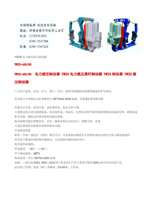
YWZ5电力液压块式制动器YWZ5-400/80YWZ5-400/80 电力液压制动器 YWZ5电力液压推杆制动器 YWZ5制动器 YWZ5液压制动器广泛用于起重、冶金、矿山、港口、码头、建筑等机械驱动装置的减速和停车制动。
其安装尺寸和制动力矩参数符合JB/T6046-2006标准。
匹配Ed系列推动器性能安全可靠、制动平稳、动作频率高、制动力矩可调。
主要摆动铰点设自润滑轴承,传动效率高、寿命长,在使用过程中始终保持两侧瓦块退距均等,避免因退距不均使一侧制动衬垫浮帖制动轮的现象。
制动弹簧布置在弹簧管内,并在一侧设有制动力矩标尺,调整方便,直观。
可通过增设附加装置实现某些附加功能:手动释放装置释放(开闸)或闭合(闭闸)限位开关,可实现制动器是否正常释放或闭合的信号显示或连锁保护。
采用带下降延时阀的推动器推动,可实现制动器的延时闭合。
使用条件和规程:环境温度: -25℃~+45℃。
空气相对湿度:≤90%海拔高度:符合GB755-2000标准。
电源:三相交流50Hz·380V. (根据用户要求也生产用于要求可提供60Hz或不同电压的产品。
适应的工作制:连续(S1)和断续(S3-60%)工作制。
一、概述YWZ 、YWZ2、YWZ3、YWZ4、YWZ5等系列液压块式制动器主要用于起重、运输、冶金、矿山、港口、建筑机械驱动装置的机械制动,具有制动平稳,安全可靠、维修方便、耗电少、寿命长、无噪音等优点。
①WYZ 系列操作次数每小时可达720次。
符合JB/ZQ4388-86标准; ②WYZ2系列操作每小时可达1200次,符合JB/ZQ4388-86标准; ③YWZ3系列操作每小时可达720次,符合GB6333-86标准; ④YWZ4系列操作每小时可达1200次,符合JB/ZQ4388-86标准; ⑤YW Z5系列操作每小时可达1200次,符合GB6333-86标准;二、使用条件1、环境温度-20℃~+50%(低于推动器改为YH-10航空液压油)2、空气相对湿度不大于90%3、一般用于三相交流电源,50HZ,380V;4、海高度符合GB755-87标准;5、在无爆炸危险,且介质中无足以腐蚀金属和破坏绝缘的气体及放电尘埃中;6、YZW、YZW3使用YTI系列推动器,一般适用于垂直工作,倾斜度不超过±去15°三、产品型号及意义四、外形尺寸图五、YWZ5技术数据、外形尺寸表(毫米)BED-80/6隔爆型电力液压推动器BED-80/12隔爆型电力液压推动器品牌:虹发产地:河南价格:1000人民币/台规格:BED-80/6,BED-80/12简要说明:BED系列电力液压推动器主要用作YWZ4,YWZ5,YWZ8,YWZ9,YWZP系列电力液压块式制动器的操作元件,广泛适用于起重运输,冶金,矿山,港口,建筑等行业。
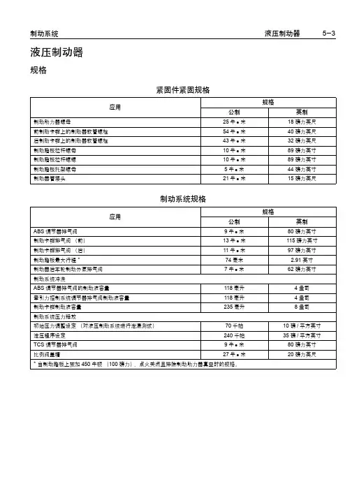
液压制动器规格紧固件紧固规格应用规格公制英制制动助力器螺母25牛z米18磅力英尺前制动卡钳上的制动器软管螺栓54牛z米40磅力英尺后制动卡钳上的制动器软管螺栓43牛z米32磅力英尺制动踏板拉杆螺母10牛z米89磅力英寸制动踏板拉杆螺螺10牛z米89磅力英寸制动踏板托架螺母5牛z米44磅力英寸制动器管接头21牛z米15磅力英尺制动系统规格应用规格公制英制ABS调节器排气阀9牛z米80磅力英寸制动卡钳排气阀(前)13牛z米115磅力英寸制动卡钳排气阀(后)11牛z米97磅力英寸制动踏板最大行程* 74毫米 2.91英寸制动器后车轮制动分泵排气阀7牛z米62磅力英寸制动系统冲洗ABS调节器排气阀的制动液容量118毫升4盎司牵引力控制系统调节器排气阀制动液容量118毫升4盎司制动卡钳制动液容量235毫升8盎司制动系统压力释放初始压力调整设定(对液压制动系统进行泄漏测试)70千帕10磅/平方英寸泄压程序设定240千帕35磅/平方英寸TCS调节器排气阀9牛z米80磅力英寸比例阀盖帽27牛z米20磅力英尺* 当制动踏板上施加450牛顿(100磅力)、点火关闭且排除制动助力器真空时的规格。
上海通用汽车零件组编号应用上海通用汽车零件组编号制动总泵04.650制动踏及托架04.625前制动器软管04.680总泵液面传感器04.650总泵储液箱04.651比例阀04.650后制动器软管04.680停车灯开关04.115真空制动助力器04.901真空制动助力器单向阀04.955示意图和布线图9326841部件定位图液压制动器部件视图发动机室左侧619488图标(1)制动液液面指示灯传感器驻车制动器619483图标(1)驻车制动器总成(2)驻车制动器指示灯开关液压制动器连接器端视图制动液液面开关连接器零件信息z15449028z2路 F GT 150 系列密封(黑色)针导线颜色电路编号功能A 黑色/白色1551接地B粉红色849制动液液面传感器信号1538760驻车制动器开关连接器零件信息z12004267z1路 F 56 系列锁止型(黑色)针导线颜色电路编号功能A浅蓝色1134驻车制动器开关信号35348DTC C0267电路说明制动液液面开关监控制动总泵中制动液液面情况。
JIANGXI AGRICULTURAL UNIVERSITY 本科毕业论文(设计)题目:常闭鼓式制动器学院:工学院*名:***学号: ********专业:机械设计制造及其自动化年级:机制082班指导教师:林金龙职称:讲师二0一二年五月摘要制动器可以分两大类,工业制动器和汽车制动器,汽车制动器又分为行车制动器(脚刹)和驻车制动器。
在行车过程中,一般都采用行车制动(脚刹),便于在前进的过程中减速停车,不单是使汽车保持不动。
若行车制动失灵时才采用驻车制动。
当车停稳后,就要使用驻车制动(手刹),防止车辆前滑和后溜。
停车后一般除使用驻车制动外,上坡要将档位挂在一档(防止后溜),下坡要将档位挂在倒档(防止前滑)。
使机械运转部件停止或减速所必须施加的阻力矩称为制动力矩。
制动力矩是设计、选用制动器的依据,其大小由机械的型式和工作要求决定。
制动器上所用摩擦材料(制动件)的性能直接影响制动过程,而影响其性能的主要因素为工作温度和温升速度。
摩擦材料应具备高而稳定的摩擦系数和良好的耐磨性。
摩擦材料分金属和非金属两类。
前者常用的有铸铁、钢、青铜和粉末冶金摩擦材料等,后者有皮革、橡胶、木材和石棉等。
块式制动器是一种的主要适用于起重运输机械的制动装置。
本论文着重介绍了其特点、关键零部件的选择或设计计算方法、主要性能参数。
除此之外还着重介绍了制动臂、等关键部件的设计参数及注意事项,同时细节方面对于制动器的静力矩也做了详细的计算设计。
关键词:制动块;制动器;制动瓦;制动轮AbstractBrakes can be divided into two categories, industrial brakes and automotive brakes, automotive brake is divided into brake (foot brake) and the parking brake. In the driving process, generally used brake (foot brake), to facilitate the process of deceleration in the forward stop, not just the car to remain intact. If the traffic Zhidongshiling when using the parking brake. When the car completely stopped, it has to use the parking brake (hand brake), to prevent the vehicle front and rear slip slide. After stopping the general addition to the parking brake, the uphill hanging in a stall to stall (after the slide to prevent), downhill to hang in the reverse gear (to prevent forward slip.) Mechanical moving parts to stop or slow down the resistance of the moment must be applied as the brake torque. Braking torque is the design, selection based on the brake, the size of the pattern and work by the mechanical requirements of the decision. Friction material used on brake (brake parts) directly affects the performance of the braking process, and the main factors affecting the performance of the working temperature and the temperature rise speed. Friction material should have high and stable friction coefficient and good wear resistance. Metallic and nonmetallic friction materials sub-categories. The former are commonly used cast iron, steel, bronze, and powder metallurgy friction materials, which have leather, rubber, wood and asbestos.Disc brake arm frame is a new major for the braking device handling equipment. This paper focuses on its characteristics, key components of the selection or design methods, the main performance parameters and some bench test results. Highlights in addition to the brake arm, loose brake components, etc. The key design parameters and considerations, while the details of the static torque for the brake has also done a detailed calculation of design.Keyword:shoe block;arrester;brake scotch;brake pulley目录1 绪论 (1)1.1制动器简介 (1)1.2 制动器工作原理 (1)2 制动器的种类和用途 (1)2.1制动器的用途 (1)2.2 制动器的种类 (2)2.2.1 根据制动器的构造形式分类 (2)2.2.2 根据操作情况分类 (4)2.2.3 根据制动器驱动方式形式分类 (5)3 块式制动器的构造 (5)3.1制动轮 (5)3.2 制动瓦块 (5)3.3制动衬料 (5)3.3.1 关于制动衬料的要求: (6)3.3.2 摩擦衬料的主要种类: (6)4 块式制动器的设计与选用 (6)4.1 毕业设计(论文)内容与技术参数: (6)4.1.1 确定制动瓦块的正压力 (8)4.1.2确定B点的力的大小; (8)4.1.3确定D点力的大小 (9)4.1.4确定弹簧力的大小 (9)4.1.5确定油泵需要的力 (9)4.2 制动瓦块的 (9)4.3 均等杠杆 (11)总结 (12)参考文献 (13)致谢 (14)1 绪论1.1 制动器简介制动器是使机械中的运动件停止或减速的机械零件。
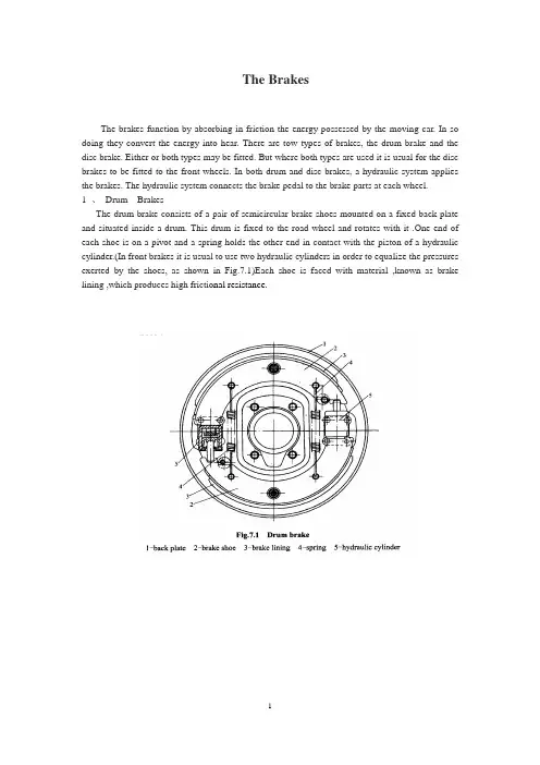
The BrakesThe brakes function by absorbing in friction the energy possessed by the moving car. In so doing they convert the energy into hear. There are tow types of brakes, the drum brake and the disc brake. Either or both types may be fitted. But where both types are used it is usual for the disc brakes to be fitted to the front wheels. In both drum and disc brakes, a hydraulic system applies the brakes. The hydraulic system connects the brake pedal to the brake parts at each wheel.1 、Drum BrakesThe drum brake consists of a pair of semicircular brake shoes mounted on a fixed back plate and situated inside a drum. This drum is fixed to the road wheel and rotates with it .One end of each shoe is on a pivot and a spring holds the other end in contact with the piston of a hydraulic cylinder.(In front brakes it is usual to use two hydraulic cylinders in order to equalize the pressures exerted by the shoes, as shown in Fig.7.1)Each shoe is faced with material ,known as brake lining ,which produces high frictio nal resistance.The hydraulic system comprises a master cylinder and the slave cylinders which are the cylinders on the road wheels. The slave cylinders are connected to the master cylinder by tubing and the whole system is filled with hydraulic fluid .A piston in the master cylinder is connected to the brake pedal, so that when the driver depresses the pedal the fluid is forced out to each slave cylinder and operates their pistons. The fluid pushes the pistons out of their cylinders. They ,in turn, push against the inner ends of the brake shoes and force them against the drums in each wheel. We say that the brakes are on. This friction of the shoes against the drums, which are fixed to the road wheels, slows down or stops the car.As the brake pedal is allowed to come up, the hydraulic fluid returns to its original position, the pistons retract, and a spring attached to each brake shoe returns it also to its original position. Free of the brake drum. Now we say that the brakes are off.(Fig.7.2)The brakes may also be operated by mechanical linkages from the foot pedal and hand brake lever. Common practice is to operate both front and rear brakes hydraulically with a secondary mechanical system operating the rear brakes only from the hand lever. One of the great advantages of hydraulic operation is that the system is self-balancing, which means that the same pressure is automatically produced at all four brakes, whereas mechanical linkages have to be very carefully adjusted for balance. Of course, if more pressure is put on one of the brakes than on the others there is a danger that the car will skid.The mechanical linkage on the rear brakes is a system of rods or cables connecting the handbrake lever to the brake-shoe mechanism, which work entirely independently of the hydraulic system. Drum brakes are prone to a reduction in the braking effort, known as “fade”, caused by the overheating of the brake linings and the drum. Fade can affect all or only some of the brakes at a time, but it is not permanent, and full efficiency returns as soon as the brakes have cooled down. However, fading is unlikely to occur except after the brakes have been used repeatedly in slowing the car from a high speed or after braking continuously down a steep hill. Descending such a hill, it would have been preferable to use engine braking by changing down into a lower gear. Drum brakes can be made less prone to fade by improving the cooling arrangements, by arranging formore air to be deflected over them, for example.2 Disc BrakesThe disc brake consists of a steel disc with friction pads operated by slave hydraulic cylinders. The steel disc is attached to the road wheel and rotates with it. Part of this steel disc is enclosed in a caliper. This caliper contains two friction pads,one on each side of the disc, and two hydraulic cylinders, one outside each pad. The pads are normally held apart by a spring, but when the driver depresses the brake pedal, pistons from the hydraulic cylinders force the pads against the sides of the disc. Because the disc is not enclosed all the way round, the heat generated when the brakes are applied is dissipated very much more quickly than it is from brake shoes which are entirely enclosed inside a drum. This means that disc brakes are less prone to fade than drum brakes.(Fig.7.3)3 、Anti-lock Brake System (ABS)The function of an anti-lock, or anti-skid, braking system is to prevent the wheels from locking under hard braking. Maximum braking force is obtained just before the wheels lock and skid. Such anti-skid system ate useful on slippery surfaces, such as ice and snow, where the wheels may lock easily. Locked wheels are dangerous because the car needs a much longer distance to stop. Locked wheels also can cause the driver to lose control.The system uses a sensor that knows when one wheel (or a pair of wheel) is skidding. (Fig.7.4) The sensor sends a signal to a computer, which signals a modulator valve. The modulator connects into the hydraulic system and can momentarily release the brake pressure and prevent the wheels from locking.(The pressure release is so fast that a driver is seldom aware of it.) pressure is then reapplied until the sensor again senses that the wheel is about to lock up. Thus, this system keeps the wheels as close to lock up as possible, without actually allowing the wheels to lock up and skid. This is called incipient lock up. Maximum braking occurs at that point. If any part of the system should fail to work, the system goes into a “fail-safe” mode. The brakes operate normally, as they would on a car that is not equipped with ABS. Today , ABS is an optional or standard feature that typically is found on expensive luxury cars and sports cars. In the future, ABS may be available for all cars.3.1、ABS overviewAnti-lock braking system is using the body of a rubber balloon, while hitting the brakes, will give brake oil pressure, feeding through to the ABS body, using of the air in the middle of the air layer to return the pressure, make wheels evade the locked points. When the wheel will arrive next locked point, brake oil pressure makes balloon in a repeat function, so can function eight to thirty times in one second equivalent constantly brake, relax, namely, similar to the "mechanical braking ". Therefore, ABS anti-lock braking system, can avoid the orientation losing control , the wheel’s lateral sliding coming up and the wheels rubbing on one point with the ground without being locked in the emergency brake,so it can make the brake friction efficiency achieves ninety percent. It also can reduce the braking consumption and prolong the brake wheel drum, disc and tire twice with the service life of the vehicle in the ABS. On the dry tarmac road or on snowy or on rainy days, the slippery performance reached 80% - 90%, 30% -10%, 15% - 20%. Ordinary braking system on a wet road surface brake, or in the emergency brake, it’s easy for wheels to be locked owing to the braking force exceeds the friction force of the tires and ground. In recent years, the consumers of the vehicle emphasis on the safety , so most of the cars have ABS listed as standard. Without ABS, emergency brake usually cause tire locked, then, the rolling friction becomes sliding friction, as a result, braking force dramatically decreased. And if front wheels are locked first, the vehicle will lose the steering ability; if the rear tires are first locked, the vehicle is easy to slide laterally , so the direction becomes impossible to control. Through electronic or mechanicalcontrol, the ABS system controls the braking fluid pressure at a fast speed to avoid the wheelslocked. Insure the tire have the biggest braking force and the turning ability when braking, and make the vehicle have the ability to evade the obstacles in emergency braking. With the rapid development of the automotive industry, safety increasingly become the important basis of that people choose and buy cars. At present the widespread adoption of holding brake system (ABS) that people can fully meet the safety of requirements. Automobile brake prevent embrace system, referred to as the ABS, is to improve the car an important device passive safety. Someone said brake prevent embrace system is auto safety measures relay belts after another major progress. Automobile braking system is the bus passengers safety is the most important relationship to one of the second systems. With the rapid development of the automotive industry, automobile safety for people appeals more and more attention. Automobile brake prevent embrace system, is another major progress to improve the safety.ABS braking system is controlled by automobile microcomputer, when braking, it can keep the wheel rotating to help driver control vehicle parking safely. The anti-locked braking system detects wheel speed by speed sensor, and then send the wheel speed signals to the microcomputer. The microcomputer controls wheel slipping rate by increasing or decreasing the brake pressure repeatedly according to the input wheel speed to keep wheel rotate. In braking process, keeping wheel rotate not only ensures the ability of controlling driving direction, but also provides higher brake force than the locked wheel in most circumstances, .3.2、The working principle of ABSIt includes control devices and ABS warning lights, in different ABS system, the structure of brake pressure adjusting device and working principle of electronic control devices are often different, the internal structure and control logic of ABS system usually includes the wheel speed sensors, brake pressure adjusting device, electronic identical and so on. In common ABS system, each wheel is installed a rotational speed sensor on the wheel speed, input the signal to electronic control device. The electronic control unit states monitoring and determination according to each wheel speed sensors’ sign al about each wheel movement, and has formed the corresponding control instruction. Brake pressure adjusting device is mainly composed by pressure regulating solenoid valves, electric pump composition and liquid container components compose an independent whole, braking main cylinder and the cylinder brake wheel connected by the brake pipe. Brake pressure adjusting device is controlled by the electronic unit to control all brake wheel cylinders’ brake pressure. The working process of ABS can be divided into general braking, brake pressure kept brake pressure decrease and brake pressure increase stage. In general braking phase, ABS doesn't intervene brake pressure control, pressure regulating electromagnetic valve assembly in various into liquid solenoid valves are no electricity and is open, each produced liquid are no electricity and electromagnetic valve is in the closed position, electric pump also operates without electricity, and brake main cylinder to each brake wheel cylinder brake lines are in communication condition, and the brake wheel cylinder to liquid brake lines are in close condition, the brake wheel cylinder brake pressure change with the output pressure brake master cylinder, the brakingprocess at this time is completely the same with conventional braking system braking process.In braking process, when the electronic control detects that the wheels primarily tend to embrace dies according to the wheel speed sensors of the wheel speed signal input, ABS came into the braking anti-lock process. For example, when the electronic control unit judges the front-right wheel tends to embrace, the electronic control unit will make control scrape the dynamic pressure front-right wheel failure into liquid solenoid valves electricity, make the fluid electromagnetic valve closed, brake main cylinder output brake fluid no longer enter into brake wheel cylinder, right now, right at the end of a fluid electromagnetic valve still energized and closed, the right brake wheel cylinder brake fluid also won't outflow, the right brake wheel cylinder scraping dynamic pressure stays certain, and other arms tend to be dead wheel with still brake pressure braking main cylinder and the increase of output pressure increases; If the right brake wheel cylinder brake pressure keep certain, the electronic control unit front-right wheel failure still tend to judge lock, the electronic control unit and move out liquid solenoid valves also electrify into a state of opening, the part right brake wheel cylinder brake wave will pass is open from fluid electromagnetic valve flow back to liquid container, make right brake wheel cylinder brake pressure holding diminishes quickly front-right wheel failure will start to eliminate death trend, with the right brake wheel cylinder brake pressure decreases, the front-right wheel under the action of inertia force will speed up gradually; accelerate gradually When the electronic control device determines the lock front-right wheel failure to completely eliminate according to the wheel speed sensors input signal, the electronic control unit makes right into the fluid electromagnetic valve and a liquid solenoid valves are without electricity, make into fluid electromagnetic valve to open, use liquid into closed electromagnetic valve, also make electric pump operation, energized to brake wheel cylinder pump brake fluid, output by brake main cylinder brake fluid electromagnetic valve into the right brake wheel cylinders, make right brake wheel cylinder brake pressure increased rapidly, opening up a front-right wheel failure and slow rotation. ABS control the sliding rate of wheels which tend to be locked through holding the brake force of wheels that tends to be locked repeatedly ,adhesion coefficient is in peak within the scope of the sliding rate, until the bus speed reduced to very low or brake main cylinder pressure no longer tend to be locked. Brake pressure to adjust cycle of frequency can reach 3 ~ 20HZ. In the ABS each has on the fluid and the fluid electromagnetic valve in corresponding at each brake wheel cylinder, but by the electronic control device to control, therefore, respectively, the brake wheel cylinder brake pressure can be independently adjustment so that four wheels are not occur braking lock phenomenon. Although various ABS structure form and working process is not exactly the same, are based on the brake holding pressure adaptive cycle adjustment of wheel which tends to be locked, to prevent the controlled wheels holding in death occurred when brake.3.3、ABS functionThe braking performance is one of main auto performance, it is also related to the security of driving. Evaluate the braking performance of a car , the basic index is brake acceleration ,braking distance and direction of braking time and braking stability.Braking stability points to that the vehicle can still be specified in the direction of auto brake when driving in the direction of track. If cars proceed high-speed brake (especially when emergency brake) and make the wheel fully embrace die, it is very dangerous. If front wheel is locked, it will make cars lose steering ability. If the rear wheel is locked, it will appear to swing tail or switching (running deviation, sideslip) especially in the road is all wet slippery case, it will cause the traffic safety great harm. Automobile braking force depends on the brake friction, but the braking force which can make the car brake to slow, and also restricted by ground adhesion coefficient. When brake produces braking force increases to certain value, the tires will appear slipping on the ground. Its sliding rateδ = (Vt - Va) / Vt x 100%δ: delta - sliding rate;Vt - theoretical speed of the car;Va - the actual speed of the car.According to the experiments confirm, when wheel sliding rate delta range from 15% to 20% , the ground adhesion coefficient reach maximum, therefore, in order to get the best braking effect, we must control the slip rate in 15% ~ 20% range.ABS function will namely decrease the brake force when the wheels will embrace dies, , and when the wheel will not hold died and increase braking force, so repeated action, braking effect is the best.3.4、The problems needing attention when ABS is used(1) After replace brake or replace hydraulic brake system components, it should exhaust the air in the brake pipe, lest affect braking system work normally.(2)The car equipped with ABS should be replaced every year. Otherwise, brake fluid hygroscopic is very strong, water will not only reduce the boiling point to make it easy to produce corrosion, and still can cause braking performance recession.(3) To examine ABS braking system should pull power firstly.制动系简介制动器通过摩擦的形式吸收运动车辆所具有的能量而起作用。
液压注意 – 用户方责任 错误或不当地选择或使用本样本或有关资料阐述的产品,可能会导致人生伤亡及财产损失! 本样本以及其它由派克汉尼汾公司及其子公司、销售公司与授权分销商所提供的资料,仅供用户专业技术人员在对产品和系统的选型进行深入调查考证时参考。
用户应全面分析自身设备的运行工况、适用的工业标准,并仔细查阅现行的样本,以详细地了解产品及系统的相关信息,通过自己的分析和试验,对产品及系统的独立的最终选择负责,确保能满足自身设备的所有性能、耐用性、维修型、安全性以及预警功能等要求。
对于派克或其子公司或授权分销商而言,应负责按用户提供的技术资料和规范,选择和提供适当的元件或系统,而用户则应负责确定这些技术资料和规范对其设备的所有运行工况和能合理预见的使用工况是否充分和准确。
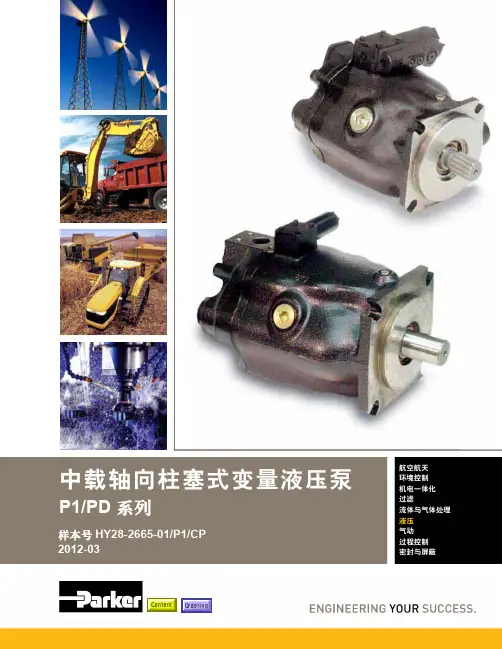
目录目录页次概述 1 订货代号 2 技术参数 4 变量控制器 5 控制选项 “C”, 压力限定(恒压)变量控制器 5 控制选项 “L”, 负载传感及压力限定变量控制器 6 控制选项 “AM”, 带遥控口的标准型先导式压力限定变量控制器 7 控制选项 “AN”, 带ISO 4401 NG06先导阀安装界面的先导式压力限定变量控制器 8 控制选项 “AE”及“AF”, 带电磁比例调节的先导式压力限定变量控制器 9 控制选项 “AMT”, “ALT”及“LOT”, 带最高压力限定的扭矩限定(恒功率)变量控制器 10 P1性能特性 11典型流量特性 11 典型总效率特性 13 典型轴输入功率特性 15 典型噪声特性 18 典型轴承寿命 20 PD性能特性 22典型流量特性 22 典型总效率特性 24 典型轴输入功率特性 26 典型噪声特性 29 典型轴承寿命 31 安装尺寸 33 P1/PD 018 33 P1/PD 028 36 P1/PD 045 40 P1/PD 060 44 P1/PD 075 49 P1/PD 100 54 P1/PD 140 59 变量控制器安装尺寸 65 可提供的扩展的液压产品 75派克汉尼汾备记派克汉尼汾概述简介, 优点派克汉尼汾简介 • 开式回路用轴向柱塞式变量液压泵 • 中压,连续工作压力280 bar • 高驱动转速型,适用于行走机械; 低噪声型,适用于工业应用 • 静音及高效的控制效能 优点 • 总结构尺寸紧凑 • 低噪声• 流量脉动小,进一步降低噪声• 采用弹性密封,不使用密封垫,从而避免外泄漏的产生• 总效率高,功耗小,减小发热• 采用带无泄漏调节装的简单变量控制器 • 符合SAE 及ISO 标准的安装法兰及油口 • 采用圆锥滚柱轴承,使用寿命长 • 全功率后驱动能力• 后部或侧面油口配置可选• 泄油口的配置对水平安装及驱动轴向上垂直安装均适用• 带有最大及最小排量调节选项 • 具有壳体至吸口单向阀选项,可延长轴封寿命 • 使用、维修方便 脉动容腔技术下列图表所示为侧向油口配置P1/PD 18, 28及45泵采用 “脉动容腔” 技术的效果,脉动容腔可降低泵出口处的压力脉动幅值40-60%,这样,无需增加成本来加装噪声缓冲元件,便可大大降低液压系统的整体噪声,P1系列 PD 系列出口压力p / bar平均压力脉动 / b a rP1 045出口压力脉动2600 rpm 无脉动容腔2600 rpm 带脉动容腔订货代号18 ml, 28 ml, 45ml派克汉尼汾P 类型 01 驱动轴 转向R 5密封材料E 油口配置0 壳体-吸口 单向阀 0 排量调节 018 排量 S 安装法兰 及油口 S 轴封 M 应用范围A 设计系列0 通轴驱动选项 C0控制选项0附加控制选项 00油漆 00修改代号系列 P D * 仅适用于045排量, “S”型安装法兰及油口00 标准型, 无修改M2 按要求修改 代号修改代号 * 适用于028及045排量 ** 仅适用于045排量 代号设计系列 A 现行设计系列5 氟碳橡胶 (FPM) 代号密封材料 A 82-2 SAE A M33x2 M27x2 BSPP 1/4”, 3/8” 101-2 SAE B M42x2 M27x2 BSPP 1/4”, 1/2” 101-2SAE B M48x2M33x2Ø38/25DN51/25BSPP 1/4”, 1/2”B ISO M33x2 M27x2 BSPP 1/4”,3/8”ISO M42x2 M27x2 BSPP 1/4”, 1/2” ISO M48x2M33x2Ø38/25DN51/25BSPP 1/4”, 1/2”代号 018排量 028排量 045排量 安装法兰及油口 安装 法兰 螺纹 油口 辅助 油口 安装 法兰 螺纹 油口 辅助 油口 安装法兰螺纹油口法兰 油口辅助 油口 S 82-2 SAE A SAE 16/12 SAE 4/6 101-2 SAE B SAE 20/12 SAE 4/8 101-2SAE B SAE 24/16Ø38/2561系列SAE 4/10M ISO M33x2 M27x2 M12x1.5 M16x1.5 ISO M42x2 M27x2 M12x1.5 M22x1.5 ISO M48x2M33x2Ø38/25DN51/25M12x1.5M22x1.5代号 018驱动轴 028驱动轴 045驱动轴 01 SAE A 11T 花键SAE B-B 15T 花键 SAE B-B 15T 花键02 SAE 19-1平键Ø0.75” SAE B-B 平键Ø1” SAE B-B 平键Ø1” 08— SAE B 13T 花键 SAE B 13T 花键 04 ISO/DIN 平键, Ø20ISO/DIN 平键, Ø25ISO/DIN 平键, Ø25 06 SAE A 9T 花键— — PD 工业液压用 代号 系列P1 行走机械用 代号 排量 018 18 ml/rev (1.10 in 3/rev) 028 28 ml/rev (1.71 in 3/rev) 045 45 ml/rev (2.75 in 3/rev) 代号 类型 P 开式回路用变量柱塞泵 U*通用 代号应用范围 S 工业液压 (PD) M 行走机械 (P1) R 顺时针 (右转)L 逆时针 (左转)代号 转向 代号 轴封 S 单唇轴封 * 并不具有控制功能,仅在运输时予以防护,详情见第7页的控制说明。

Hydraulically and Pneumatically Operated Clutches and BrakesP-8359-SG-A4 9/173Stromag | +49 2303 102-0P-8359-SG-A4 9/17In conjunction with flexible Stromag couplings, drives subject to impact or shock loads such as road millers or stone crushers are comfortably controlled.Hydraulically or pneumatically operated brakes in drives ensure stability of construction machinery and keep rotary drives in the required position. Winches on cranes or ships are also braked andheld under difficult conditions.High torques and small dimensions are two significant characteristics of hydraulically operated clutches and brakes. By selecting suitablefriction linings and influencing pressure build-up, the operating characteristics can be adapted to meet specific requirements.This brochure contains several clutch and brake series on the basis ofwhich we can develop solutions tailored to your particular application.Hydraulically or pneumatically operated clutches and brakes are highly advanced and reliable components for modern energy-efficient drives.These units control individual drive trains on modern agricultural machinessuch as combine harvesters and forage harvesters, as well as the powerflow in various hybrid drives.• Universal, hydraulically operated multi-disc clutch. Suitable for wet or dry operation.• Various friction linings with different properties are available.• Transmittable torques from 200 Nm to 140,000 Nm.• Other sizes and customer-specific adaptations available on request.Pneumatic option also available.INSTALLATION IN GEARBOX (WET OPERATION)Stromag KMK for use in gearboxes (wet operation) with optional disc oilflushing. Hydraulic and cooling oil supplied via the transmission shaft.Stromag KMK for use in gearboxes (wet operation) with optional discoil flushing. Hydraulic and cooling oil supplied via integrated radial oilsupply (KRE).No bores in the transmission shaft.MOUNTING ON GEARBOX (DRY OPERATION)Stromag KMK as a shaft-pulley connection for use outsidegearboxes (dry operation). Hydraulic oil can be supplied axially through theshaft. Available as a completely assembled and bearing supported unit.Stromag KMK as a shaft-cardan shaft connection for use outsidegearboxes (dry operation). Hydraulic oil supplied axially through theshaft. Available as a completely assembled and bearing supported unit. P-8359-SG-A4 9/17• Hydraulic multi-disc clutch with hammer head discs.• Designed specially for dry operation on drivessubject to torsional vibrations.• Transmittable torques from 1,600 Nm to 6,000 Nm.• Other sizes and customer specific adaptationsavailable on request.• Pneumatic option also available.Stromag KUK as a basic type. For use outside gearboxes(dry operation). Hydraulic oil supplied axially through the shaft.Customer-specific adaptations of shaft and external body connectionspossible.Stromag KUK as a shaft-pulley connection for use outsidegearboxes (dry operation). Hydraulic oil supplied axially through theshaft. Available as a completely assembled and bearing supported unit.• Hydraulic clutches with low or backlash-free torque• Transmission via diaphragms. Minimal residualtorque when open. Suitable for direct use on internalcombustion engines.• Transmittable torques from 600 Nm to 5,000 Nm.• Other sizes and customer-specific adaptationsavailable on request.• Pneumatic option also available.Stromag KHM as a shaft-pulley connection. Backlash-freepower transmission on pulley side through external body and pistonwith diaphragm guidance. Friction lining carrier on shaft side with lowwearing, wide sliding gear.Stromag KHM for engine mounting. Backlash-free powertransmission via diaphragm guided pistons and frictionlinings. Drag torque free when open. Connection forSAE flywheels. Housings for SAE sizes 1 to 4 possible.5Stromag | +49 2303 102-0P-8359-SG-A4 9/17Stromag KHA with additional carrier for heavy-duty pilot bearing andbracing springs for reducing drag torque.Connection for standard flywheels. Housings for SAE sizes 1 to 4possible.Stromag KHA with flexible Periflex® VN couplings for drives particularlysubject to torsional vibrations. Connection for SAE flywheels. Housingsfor SAE sizes 1 to 4 possible.Stromag KHR as a "Two in One" combination in SAE housing on dieselengine with direct flange-mounted cardan shaft.Stromag KHR as a complete unit for preassembly with supportedexternal body as a shaft-shaft connection.• Hydraulically operated multi-disc clutches withrotating piston. For use mainly outside gearboxes(dry operation) when no axial oil supply is possible• Transmittable torques from 200 to 12,000 Nm• Other sizes and customer-specific adaptationsavailable on request.• Pneumatic option also available• Dry, hydraulically operated multi-disc clutches inhousings with SAE connection sizes for mounting ondiesel engines• Reinforced inner discs and outer discs with hammerhead for low gear wear.• Transmittable torques from 500 Nm to 5,000 Nm.• Other sizes and customer-specific adaptationsavailable on request.• Pneumatic option also available. P-8359-SG-A4 9/17Stromag KMB standard type for direct mounting on shaft end ongearbox or motor. Alternatively with or without sealed shaft bushing.Stromag KMB adapted customer-specific requirements.Integrated in a gearbox.• Hydraulically released, spring-applied multi-disc brake in own housing with standard flangeconnections for mounting between gearbox andhydraulic motors• Flange types and shaft connections according tocustomer requirements• Transmittable torques from 270 to 2,000 Nm• Other sizes and customer specific adaptationsavailable on request• Pneumatic option also available.Stromag KMB.ZM mounted between gearbox and hydraulic motor.Connection flanges according to SAE standard orcustomer specifications.• Universal hydraulically released, spring-appliedmulti-disc brake. For use in or outside gearboxes(wet or dry operation) as well as a holding brakewith emergency stop function.• Various friction linings with different properties areavailable• Transmittable torques from 100 Nm to 130,000 Nm• Other sizes and customer specific adaptationsavailable on request• Pneumatic option also available7Stromag | +49 2303 102-0P-8359-SG-A4 9/17The Brands of Altra Industrial MotionCouplingsAmeridrivesGuardian Couplings HucoStromagTB Wood’sGeared Cam Limit Switches Stromag Electric Clutches & BrakesInertia DynamicsMatrixStromagWarner ElectricLinear ProductsWarner LinearEngineered Bearing AssembliesKilianHeavy Duty Clutches & BrakesIndustrial ClutchStromagSvendborg BrakesWichita ClutchBelted DrivesTB Wood’sGearingBauer Gear MotorBoston GearDelroyd Worm GearNuttall GearOverrunning ClutchesFormsprag ClutchMarland ClutchStieber ClutchStromag FacilitiesEuropeGermanyHansastraße 12059425 Unna - Germany+49 (0) 23 03 102 0Clutches & Brakes, Couplings, Geared Cam Limit Switches, Discs, Wind BrakesDessauer Str. 1006844 Dessau-Roßlau - Germany+49 (0) 340 2190 0 Electromagnetic Clutches & Brakes FranceAvenue de l’Europe18150 La Guerche sur L’Aubois - France +33 (0)2 48 80 72 72Industrial Caliper & Drum Brakes Great Britain11 Fleming ClosePark Farm Industrial Estate Wellingborough NN8 6UF+44 (0)1933 675494 Electromagnetic Clutches & Brakes, Industrial Caliper Brakes North AmericaUSA31 Industrial Park RoadNew Hartford, CT 06057 - USA860-238-4783Electromagnetic Clutches & Brakes300 Indiana Highway 212Michigan City, IN 46360 – USA219-874-5248Couplings2800 Fisher Rd.Wichita Falls, TX940-723-3400Geared Cam Limit Switches,Industrial Caliper & Drum BrakesAsia PacificChinaT40B -5, No. 1765 Chuan Qiao RoadPudong 201206, Shanghai - ChinaTel +86 21-60580600Clutches & Brakes, ElectromagneticClutches & Brakes, Couplings, IndustrialCaliper & Drum Brakes, Discs,GearedCam Limit Switches, Wind BrakesIndiaGat No.: 448/14, Shinde Vasti, NighojeTal Khed, Pune- 410 501+91 2135 622100Clutches & Brakes, ElectromagneticClutches & Brakes, Couplings, IndustrialCaliper & Drum Brakes, Discs,GearedCam Limit Switches, Wind Brakes Hansastraße 120 59425 Unna - Germany +49 2303 102-0P-8359-SG-A4 9/17。
液压离合器制动器样本中文
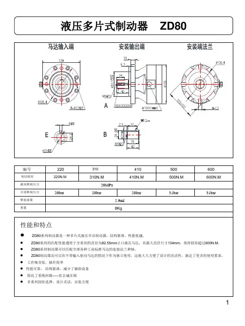
/–..../摩擦片数量的选择会大大地影响扭矩传递能力和啮合频率。
可以定量控制冷却油的流量,从而可以有效的对摩擦片进行散热。
0023系列可以采用双键槽实现轴和轮毂的固定,0123系列可以采用双键槽,也可以采用涨紧套实现轴和轮毂的固定摩擦材料组合:钢/烧结材料工作压力:60巴压力和冷却油:旋转接头应用范围:压力机、冲压生产线、剪切设备和其他锻压设备Sinus??0021-007这种结构的离合器广泛应用在紧凑型的设备上,离合器的占用空间很小。
摩擦材料组合:钢/烧结材料工作压力:18至20巴压力和冷却油:旋转接头应用范围:机床设备、车辆、固定和移动行车以及其他升降设备Sinus??0021-3.3这是一种用于重载驱动系统的离合器,标准结构为凸台外壳,无“紧急啮合装置”。
也可以提供带“紧急啮合装置”的结构。
这种离合器也可以有大孔径结构,如果用于船舶行业,可以按客户的要求由船级社对离合器进行认证。
由于传递扭矩很大,也是由于使用了钢/烧结材料,磨损量很少,奥特林豪斯生产的Sinus??多片离合器、制动器和组合式离合器制动器可以广泛应用在机械工程、车辆和传动系统上。
经过精确控制的冷却油进入摩擦片内,根据不同的使用场合,可以有效的进行散热。
可以说这种离合器和制动器无磨损,基本上不需要维修~/0023和0123应用在压力机、剪切设备和其他锻压产品上的组合离合器制动器被认为是最安全可靠的离合器制动器,完全符合CE规定的相关标准。
工作压力:25巴压力和冷却油:旋转接头应用范围:船舶用换向齿轮、变距推进器传动系统和多级马达传动系统Sinus??0-002这种离合器用于各种重型传动系统,啮合频率很高;有法兰盘结构或凸台外壳结构,无“紧急啮合装置”。
也可以提供“紧急啮合装置”。
这种离合器可以按照客户的要求由船级社进行认证。
摩擦材料组合:钢/烧结材料工作压力:24巴压力和冷却油:旋转接头应用范围:船舶用换向齿轮、变距推进器传动系统、多级马达传动系统和动力输出装置
0022-..0/..9这是一种弹簧制动安全制动器外壳为不对中结构,所以这种制动器主要安装在轴端和齿轮箱的外壳上。
其他变型结构还包括闭式法兰盘和开式法兰盘结构,这样轴可以从中穿过。
“湿式摩擦片”可以浸泡在油里进行润滑,或借助摩擦片箱体内的油进行润滑,取决于使用情况。
这种制动器在液压系统出现故障时可以借助“紧急松脱装置”机械松脱。
摩擦材料组合:钢/烧结材料;干式或湿式工作压力:最大320巴压力和冷却油:固定缸体外径的外侧应用范围:广泛应用在机械工程,特别是行车、锚机和绞车的液压马达上002-..1这是一种弹簧制动安全制动器,外壳有对中和负载功能。
“湿式摩擦片”可以浸泡在油里进行润滑,或借助摩擦片箱体内的油进行润滑,取决于使用情况。
这种制动器在液压系统出现故障时可以借助“紧急松脱装置”机械松脱。
摩擦材料组合:钢/烧结材料;干式或湿式工作压力:最大320巴压力和冷却油:固定缸体外径的外侧应用范围:应用在电机(液压马达)和驱动件之间0022-.20这是一种占用空间很小的结构,应用在设备空间有限的场合。
外壳有对中和负载功能。
摩擦材料组合:钢/烧结材料;干式或湿式工作压力:最大320巴压力和冷却油:固定缸体外径的外侧应用范围:各种齿轮箱、行车和其他升降装置。
0022-.20奥特林豪斯可以提供各种也液压驱动离合器和制动器配套的附件,并可以与所使用的设备配套使用。
附件包括:??压力安全阀??全套模块化离合器制动器控制系统??单双通道旋转接头(详见样本)??为离合器和制动器提供压力和冷却油的液压泵站??油冷/风冷装置或油/水热交换器??用于离合器和制动器的密封外壳0-022-304系列弹簧制动液压松脱多片制动器,安装在锚机或绞车传动装置上0-123系列弹簧制动液压松脱多片制动器,
安装在锚机或绞车传动装置上0-123系列液压驱动组合式离合器/制动器,安装在锚
机或绞车传动装置上,安装在压力机传动系统上Nm。