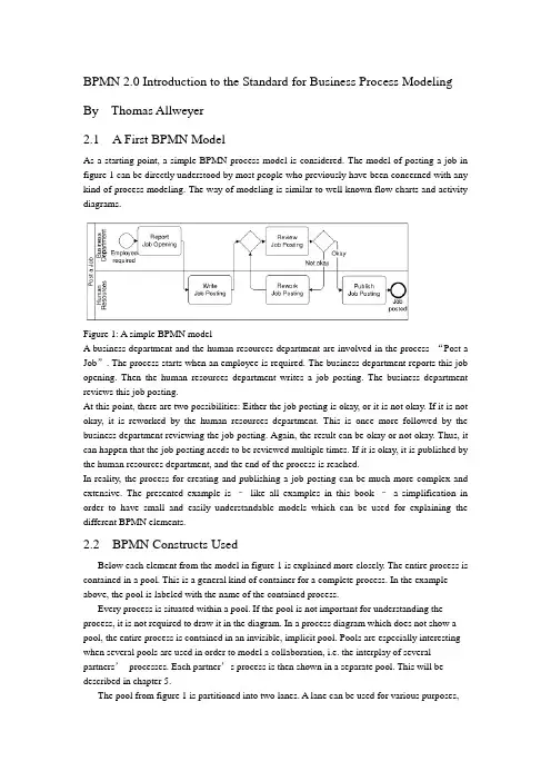
BPMN 2.0 Introduction to the Standard for Business Process Modeling By Thomas Allweyer2.1 A First BPMN ModelAs a starting point, a simple BPMN process model is considered. The model of posting a job in figure 1 can be directly understood by most people who previously have been concerned with any kind of process modeling. The way of modeling is similar to well known flow charts and activity diagrams.Figure 1: A simple BPMN modelA business department and the human resources department are involved in the process “Post a Job”. The process starts when an employee is required. The business department reports this job opening. Then the human resources department writes a job posting. The business department reviews this job posting.At this point, there are two possibilities: Either the job posting is okay, or it is not okay. If it is not okay, it is reworked by the human resources department. This is once more followed by the business department reviewing the job posting. Again, the result can be okay or not okay. Thus, it can happen that the job posting needs to be reviewed multiple times. If it is okay, it is published by the human resources department, and the end of the process is reached.In reality, the process for creating and publishing a job posting can be much more complex and extensive. The presented example is –like all examples in this book –a simplification in order to have small and easily understandable models which can be used for explaining the different BPMN elements.2.2 BPMN Constructs UsedBelow each element from the model in figure 1 is explained more closely. The entire process is contained in a pool. This is a general kind of container for a complete process. In the example above, the pool is labeled with the name of the contained process.Every process is situated within a pool. If the pool is not important for understanding the process, it is not required to draw it in the diagram. In a process diagram which does not show a pool, the entire process is contained in an invisible, implicit pool. Pools are especially interesting when several pools are used in order to model a collaboration, i.e. the interplay of several partners’processes. Each partner’s process is then shown in a separate pool. This will be described in chapter 5.The pool from figure 1 is partitioned into two lanes. A lane can be used for various purposes,e.g. for assigning organizational units, as in the example, or for representing different components within a technical system. In the example, the lanes show witch of the process’s activities are performed by the business department and which by the human resource department.Pools and lanes are also called “swimlanes”. They resemble the partitioning of swimming pools into lanes. Every participant of a competition swims only in his own lane.The process itself begins with the start event “Employee required”. Processes usually have such a start event. Its symbol is a simple circle. In most cases it makes sense to use only one start event, not several ones.A rounded rectangle represents an activity. In an activity something gets done. This is expressed by the activities’names, such as “Report Job Opening”or “Review Job Posting”.The connecting arrows are used for modeling the sequence flow. They represent the sequence in which the different events, activities, and further elements are traversed. Often this is called control flow, but in BPMN there is a second type of flow, the message flow, which influences the control of a process as well, and is therefore some kind of control flow, too. For that reason, the term “sequence flow”is used. For distinguishing it from other kinds of flow, it is important to draw sequence flows with solid lines and filled arrowheads.The process “Post a Job”contains a split: The activity “Review job posting”is followed by a gateway. A blank diamond shape stands for an exclusive gateway. This means that out of several outgoing sequence flows, exactly one must be selected. Every time the right gateway in the job posting-process is reached, a decision must be taken. Either the sequence flow to the right is followed, leading to the activity “Publish Job Posting”, or the one to the left is selected, triggering the activity “Rework Job Posting”. It is not possible to follow both paths simultaneously.The logic of such a decision is also called “exclusive OR”, abbreviated “XOR”. The conditions on the outgoing paths determine which path is selected. If a modeling tool is used and the process has to be executed or simulated by a software program, then it is usually possible to formally define exact conditions. Such formal descriptions, which may be expressed in a programming language, can be stored in special attributes of the sequence flows.If, on the other hand, the purpose of a model is to explain a process to other people,then it is advisable to write informal, but understandable, statements directly into the diagram, next to the sequence flows. The meaning of “okay”and “not okay”after the activity called “Review Job Posting”is clear to humans –a program could not make use of it.Gateways are also used for merging alternative paths. In the sample process, the gateway on the left of the activity “Review Job Posting”merges the two incoming sequence flows. Again, this is an exclusive gateway. It expects that either the activity“Write Job Posting”or “Rework Job Posting”is carried out before the gateway is reached –but not both at the same time. It should be taken care to use a gateway either for splitting or for joining, but not for a combination of both. The last element in the example process is the end event. Like the start event it has a circle as symbol –but with a thick border.2.3 Sequence Flow LogicThe flow logic of the job posting process above is rather easy to understand. In more complex models it is sometimes not clear how the modeled structure exactly is to be interpreted. Therefore it is helpful if the meaning of the sequence flow’s elements is defined in an unambiguous way.The logic of a process diagram’s sequence flow can be explained by “tokens”. Just as in a board game tokens are moved over the board according to the game’s rules, one can imagine moving tokens through a process model according to BPMN’s rules.Every time the process is started, the start event creates a token (cf. figure 2). Since the job posting process is carried out more than once, many tokens can be created in the course of time. Thereby it can happen that the process for one job posting is not yet finished, when the process for posting another job starts. As it moves through the process, each token is independent from the other tokens’movements.Figure 2: A start event creates a tokenThe token that has been created by the start event moves through the sequence flow to the first activity. This activity receives a token, performs its task (in this case it reports a job opening), and then releases it to the outgoing sequence flow (cf. figure 3).Figure 3: An activity receives a token and forwards it after completionThe following activity forwards the token. It then arrives at the merging exclusive gateway. The task of this gateway is simple: It just takes a token that arrives via any incoming sequence flow and moves it to the outgoing sequence flow. This is shown in figure 4. In case A, a token arrives from the left, in case B from below. In both cases the token is routed to the outgoing sequence flow to the right.Figure 4: Routing of a token by a merging exclusive gatewayThe task of the splitting exclusive gateway is more interesting. It takes one arriving token and decides according to the conditions, to which sequence flow it should be moved. In case A in figure 5, the condition “okay”is true, i.e. the preceding review activity has produced a positive result. In this case, the token is moved to the right. Otherwise, if the condition “not okay”is true, the token is moved to the downwards sequence flow (case B).The modeler must define the conditions in such a way that always exactly one of the conditions is true. The BPMN specification does not state how to define conditions and how to check whichconditions are true. Since the considered process is not executed by software, the rather simple statements used here are sufficient. Otherwise, it would be necessary to define the conditions according to the requirements and rules of the software tool.The token may travel several times through the loop for reworking the job posting. Finally it arrives at the end event. This simply removes any arriving token and thus finishes the entire process (figure 6).Figure 5: Routing of a token by a splitting exclusive gatewayThe sequence flow of every process diagram can be simulated in this way with the help of tokens. This allows for analyzing whether the flow logic of a process has been modeled correctly.It should be noted that a token does not represent such a thing as a data object or a document. In the case of the job posting process, it could be imagined to have a document “job posting”flowing through the process. This document could contain all required data, such as the result of the activity “Review Job Posting”. At the splitting gateway, the decision could then be based on this attribute value. However, the BPMN sequence flow is constrained to the pure order of execution. The tokens therefore do not carry any information, other than a unique identifier for distinguishing the tokens from each other. For data objects there are separate BPMN constructs which will be presented in chapter 10.2.4 Presentation OptionsUsually pools are drawn horizontally. The preferred direction of sequence flow is then from left to right. On the other hand, it is also possible to use vertical pools and to draw the sequence flow from top to bottom, as in the example in figure 7.It makes sense to decide for only one of these possibilities –horizontal or vertical. Nevertheless there are modeling tools which only support horizontal modelingFigure 6: An end event removes an arriving tokenFigure 7: Vertical swimlanes and nested lanesFigure 7 also shows an example of nested lanes. The lane labeled “Sales”is partitioned into the two lanes “Sales Force”and “Order Processing”. In principle it is possible to partition these lanes again, etc., although this only makes sense up to a certain level of depth.It is not prescribed where to place the names of pools and lanes. Typical are the variants selected for figure 1 and figure 7. Here the names are placed on the left of the pools or lanes, or at the top for the vertical style, respectively. The name of a pool is separated by a line. The names of the lanes, however, are placed directly within the lanes. A separation line is only used for a lane that is partitioned into further sub-lanes. Lanes can also be arranged as a matrix. The procurement process in figure 8 runs through a business department and the procurement department, both of which span a branch office and the headquarters. When a demand occurs in a branch’s business department, this department reports the demand. In the next step, the procurement is approved by the same department in the headquarters. The central part of the procurement department then closes a contract with a supplier, followed by the branch’s purchasing department carrying out the purchase locally.Although the BPMN specification explicitly describes the possibility of such a matrix presentation, it is hardly ever applied, so far.12.2 Message CorrelationThe contents of the message flows within one conversation are always related to each other. For example, all messages that are exchanged within one instance of the conversation “Process Order for Advertisement”relate to the same advertisement order. It is therefore possible to use the order ID for the correlation, i.e. the assignment of messages to a process instance. If a customer receives an advertisement for approval, he can determine the corresponding order –and thus the process instance –based on the order ID. All messages of a conversation have a common correlation.A simple conversation which is not broken down into other conversations is called communication. Therefore, the lines are called communication links (the specification draft at some places alsocalls them conversation links). A conversation has always communication links to two or more participants.If the end of a communication link is forked, multiple partners of the same type can be part of the communication, otherwise exactly one. “Process Order for Advertisement”has exactly one customer and one advertising agency as participants, but multiple designers. Therefore, the designer’s pool contains a multiple marker. However, having only the multiple marker in the pool is not sufficient. The conversation “Handle order for an illustration”, for example, has only one designer as participant. Therefore, the respective end of the communication link is not forked.12.3 Hierarchies of ConversationsBesides communications, it is also possible to use sub-conversations. Similar to sub-processes they are marked with a ‘+’-sign. The details of a sub-conversation can be described in another conversation diagram. The diagram of a sub-conversation can only contain those participants who are linked to the sub-conversation within the parent diagram.Figure 171 shows the detailed conversation diagram for the sub-conversation “Process Order for Advertisement”As can be seen from this diagram, it is also possible to draw message flows directly into the conversation diagram. Other than collaboration diagrams, conversation diagrams are not allowed to show processes in the pools or choreographies between the pools.Figure 171: Conversation diagram for sub-conversation “Process Order for Advertisement”The diagram contains those message flows that are related to the same order. To be more precise, they relate to the same inquiry. At the beginning, an order has not been placed yet, and not every inquiry turns into an order. Therefore, the common reference point is the inquiry.Besides the explicitly displayed message flows between customer and advertising agency, the diagram also contains the communication “Assignment of Graphics Design”. All message flows of this communication are also related to the same inquiry, but this information is not sufficient for the advertising agency in order to assign all incoming messages correctly. This is due to the fact that availability requests are sent to several designers. The advertising agency has to correctly assign each incoming availability notice to the correct availability request. Thus, additional information is required for correlating these messages, e.g. the IDs of the availability requests.Therefore it is possible to define a separate communication for the message flows between advertising agency and designer. The message exchanges of this communication can also be modeled in a collaboration diagram (figure 172) or in a choreography diagram (figure 173). Of course, it is also possible to show the message flows of the entire sub-conversation within a single diagram (figures 161 and 162 in the previous chapter).Figure 172: Collaboration diagram for communication “Assignment of Graphics Design”Like sub-processes, sub-conversations can also be expanded, i.e. the hexagon is enlarged, and the detailed conversation is shown in its interior. However, it is graphically not easy to include, for example, the contents of figure 171 into an expanded sub-conversation in figure 170. Unfortunately, the BPMN specification draft does not contain any examples for expandedsub-conversations either.。