EtherPeek-NX-2.1软件的基本使用方法
- 格式:doc
- 大小:274.50 KB
- 文档页数:7

如何用EtherPeek NX抓取大量报文一、目的大部分的抓包软件都可以提供Capture功能,但通常是将报文放在内存中,只有在点击保存时,才会将内存中的文件写入到硬盘上,如果想要抓取大量报文,例如抓取一个大文件的传输过程,大部分软件都无能为力,因为缓存能力有限,这里介绍如何利用Ethereek NX 软件实现这一功能。
二、安装EtherPeek软件是一个通用软件,可以在网络上下载,通常需要注册码,可自行解决。
三、配置本次讲解用EtherPeek NX版本,即EtherPeek NX for Windows v2.1版本,其他版本大同小异。
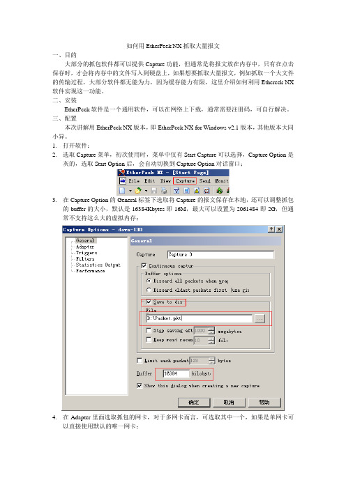
1.打开软件:2.选取Capture菜单,初次使用时,菜单中仅有Start Capture可以选择,Capture Option是灰的,选取Start Option后,会自动切换到Capture Option对话窗口;3.在Capture Option的General标签下选取将Capture的报文保存在本地,还可以调整抓包的buffer的大小,默认是16384Kbytes即16M,最大可以设置为2061484即2G,但通常不支持这么大的虚拟内存;4.在Adapter里面选取抓包的网卡,对于多网卡而言,可选取其中一个,如果是单网卡可以直接使用默认的唯一网卡;5.Triggers可以设置抓包的触发条件;6.Filters可以为收到的报文设置一个过滤,只Capture过滤的报文;7.Statistics Output可以将统计数据已HTML的格式保存成report;8.Performance可以查看启用和取消部分性能统计;9.点击确认,就开始Capture报文,这些报文会在抓满Buffer后,以文件的形式存在指定的路径中,如果报文非常多,那就保存很多文件,文件名以本机的抓包起始时间命令。
注意:1.上述方式可以抓取大量的数据报文,但前提是抓包的PC机性能需要高于发送和接收的设备,因为抓包的PC需要通过EtherPeek抓到报文后,还要写入硬盘,写入硬盘的速率太低会导致写入时间太长,在写入期间的数据报文是不会被抓取的;2.EtherPeek中的抓包buffer不宜设置过大,因为文件太大,PC系统在写入硬盘时,耗时太长,同样存在写入期间的数据报文无法抓取的情况;。

EtherScope ™nXGPortable Network ExpertDATA SHEETThe EtherScope nXG has two sets of native Wi-Fi network interfaces: a 4x4 adapter that scan and test Wi-Fi networks, and a 1x1 adapter for remote control connection and testing. Both interfaces support 802.11a/b/g/n/ac and can show analysis of utilization and status of Wi-Fi channels, SSIDs, BSSIDs, access points, client devices, and interferers. The EtherScope nXG provides visibility of Wi-Fi 6 devices.The EtherScope nXG has two Ethernet ports. The main test RJ-45 port supports Multi-Gig networks from 10/100/1000Mbps to 2.5/5/10G to verify link speed and duplex advertised and connected. It can request and verify PoE power under load from up to 90W PSE’s. Alternatively, it can interface to fiber networks via single/multi-mode SFP+ to test 1/10Gbps fiber-based Ethernet. The second RJ-45 management port connects to 10/100/1000Mbps Ethernet for remote control, and conducts network scanning and tests where needed. It is also the port for cable testing.The EtherScope nXG has built-in Bluetooth v5/BLE and USB interfaces to discover and Key FeaturesNEWUSB-AMain Ethernet Test Ports (RJ-45 & SFP)Cable Test & ManagementPortsUSB-CThe EtherScope nXG can stress critical network links, such as switch ports to servers/storage/Wi-Fi access points, uplinks or WAN links, with up to four simultaneous data streams at up to 10G line-rate. It verifies the link’s compliance to service level agreements (SLA) based on throughput, packet loss, delay and jitter against peers such as EtherScope nXG(s), OneTouch™ 10G(s), OptiView® XG(s) or a software reflector agent(s).The EtherScope nXG uses the popular iPerf v3 network test algorithm to test against the NetAlly Test Accessory. It determines TCP or UDP application throughput through its Wi-Fi or wired interfaces.Settings for data streams and thresholds for VoIP or video service can be stored and recalled where needed, saving configuration time.For key servers/services in the cloud or Internet, engineers can pre-define tests and thresholds to verify their connectivity and performance using ping, TCP connect, HTTP, or FTP. Continuous testing with response time measurements is available to verify consistency and identify intermittent issues. These tests can be easily recalled by field technicians to reduce configuration time or mistakes, to get more done faster.EtherScope nXG OneTouch™OptiView® XGWindows-basedSo ware AgentLinkRunner® AT LinkRunner G2Test AccessoryEtherScope nXGPEERS REFLECTORS bi-directionalround-tripLINE RATETEST IPERF TEST EthernetPerformance test with up to 4 streams and 4 end pointsFrame loss, jitter, and latency chartediPerf throughput test with TCP or UDP frames HTTP test against awebserver10G copper/fiber wired and Wi-Fi performance testsfor critical links and key devicesThe EtherScope nXG automatically discovers your network through its dual set of Wi-Fi and Ethernet test interfaces immediately upon power-up. The discovery provides quick security and health audits of the network devices across multiple VLANs and all Wi-Fi channels.Devices are classified and correlated to provide complete visibility of their name, network addresses, VLAN, SSID, device type, and whereavailable, traffic statistics. Discovery results can be directly uploaded to thecomplimentary Link-Live Cloud Service for storage or converted to CSV/PDFfiles as documentation.The EtherScope correlates the discovery result from the wired and Wi-Fi networks so that it is possible to show the name and IP address of Wi-Fi devices connected to the network. EtherScope nXG makes it easy to discover the actual identity of a Wi-Fi device while most other Wi-Fi tools only show the MAC address.EtherScope nXG’s discovery can be enriched by accessing SNMP MIBsof infrastructure devices. It shows details such as device configuration summary, interface configuration and traffic detail, SSIDs supported by WLAN Controllers, and devices directly connected to switches. Community strings entered are concealed from view.Discover possible security risks caused by users and others: 2nd DHCP offers indicating possible rogue servers, APs with different security schemes, unknown switches granting access to multiple devices, rogue Wi-Fi devices probing the network, and hidden SSIDs.The EtherScope nXG discovery automatically detects problems. It shows possible cause(s) for each problem detected, and it has integratedtroubleshooting tools to investigate further to get to root cause.Auditing and documenting network security andhealthWi-Fi Device shown with name & IP address Filters available to narrow down to devices of interestAdditional filters available for device types Device detail showingVLAN, interfaces, uptime, &more with drill-downDevice interfaces sortable by VLAN, connected devices, & utilization Interface traffic statistic - correlated 24 hr charts to detect intermittent eventsThe EtherScope nXG has out-of-the-box AutoTest profiles with best practice pass/fail thresholds for quick assessment of network configurations and services of Wi-Fi and wired networks.Ethernet Network: switch port PoE characteristics, link speed advertised vs negotiated, DHCP/DNS/Gateway availability and accessibility.Air Quality: assess number of APs, co-channel and adjacent channel interference, and channel utilizationWi-Fi Network: supports various authentication and security schemes to connect to SSIDs/BSSIDs for coverage by signal/noise, and DHCP/DNA/Gateway availability and accessibility.Wi-Fi Air Quality - detects oversubscribed channelsWi-Fi SSID connectivity &coverageSimplifies tasks and empowers technicians to verify complex networks with next generation AutoTestConfigurationTestingDocumentationCollaborationPath Analysis: shows the switch/router path connecting the EtherScope nXG to an IP device on across wired and Wi-Fi networks, and even beyond the local network, e.g., from the EtherScope nXG’s Wi-Fi port to a server in the cloud or data center on the Internet. The EtherScope nXG offers built-in tools to conduct further analysis of the devices along the path: view configuration, interface traffic statistics, launch Telnet or browser, conduct port scan, ping and more.Packet Capture: from both the Wi-Fi and Ethernet test interfaces. You can capture up to 10G line-rate to create a PCAP file of up to 1Gigabyte. Packet slicing and filtering are supported, and PAP files can be uploaded to theLink-Live Cloud Service for easy sharing.Cable Test: determine length, shorts, and split pairs and locate opens on UTP cable. Verify the wiremap of UTP and ScTP cable with a WireViewadapter. It can generate either analog tone or the unique digital tone for theFluke Networks IntelliTone™ Probe for quick cable tracing.Android Apps: Users can download apps from the Link-Live app store toaccomplish many tasks in addition to testing.Multiple advanced troubleshooting tools in oneMultiple profiles can be created for complex networks with multiple VLANs supported per switch port, and Wi-Fi networks with multiple SSIDs each with its own set of IP targets. These can then be organized into profilegroups that execute each test against each profile in sequence. The result is that multiple VLANs, and SSIDs can be verified and documented in one go. Since the pre-defined profiles can be executed individually, the profiles group serves as a resource for technicians to verify each specific VLAN orSSID during troubleshooting. With profile groups, engineers can transfertheir network configuration and test knowledge to technicians, saving training time and effort.Simplifies tasks and empowers technicians to verify complex networks withnext generation AutoTest (continued)Tools, such as a browser, are available to conduct device level investigationCable test with Wiremap detecting distance to fault Path Analysis shows the device & interfaces that UDP/TCP traffic traversesShows the interfaces of devices present in pathanalysisNBASE-T switch networkvalidationAdd & customize profiles for standardized testingExamples of Android apps available to download to EtherScope nXGThe EtherScope nXG has dedicated Wi-Fi and Ethernet management ports that empower a more experienced/knowledgeable remote engineer to control the EtherScope nXG to collaborate with technicians on-site. At locations with no Internet service, the Wi-Fi Management Port canconnect to a personal Wi-Fi hotspot for remote control, and upload results to the Link-Live Cloud Service.Apart from providing remote access, the dedicated management ports are used for discovery to access to SNMP MIBs of devices via a management VLAN isolated from client VLANs, and conduct Ping/TCP Connect tests and iPerf tests.Ordering GuideEXG-200Includes: (1) EXG-200 mainframe with Li-ION battery, G3-PWRADAPTER, SFP+MR-10G850, Inline RJ-AccessoriesSpecificationsNOTE: The battery will not charge if the internal temperature of the tester is above 122°F (50°C).Certifications and Complaince©2019 NetAlly. NetAlly® is a registered trademark of LinkRunner® LLC dba NetAlly. Third-party trademarks mentioned are the property of their respective owners./products/etherscopenxgSpecifications (continued)。


Combine flexibility in Remote I/O configurationwith the speed and determinism of EtherCAT.•The EtherCAT Coupler Unit is the link between the EtherCAT MachineControl network and the NX-series I/O Units. With I/O Units ranging frombasic I/O's to high-speed synchronous models, the NX-series is the perfectmatch for the Sysmac Machine Automation Controllers.Features•Up to 63 NX-IO Units can be connected to one EtherCAT Coupler Unit. Standard and high-performance units can be mixed.*1•High-speed remote I/O control is possible at the fastest communication cycle of 125 μs.*2•Each Coupler plus its I/O form just a single EtherCAT node on the network.•I/O control and safety control can be integrated by connecting Units for safety.•The Coupler supports the EtherCAT Distributed Clock (DC) and propagates this to synchronous I/O units.•The node address can be fixed by rotary switches, or set by software. Choose the method that best suits your way of engineering.•Slave configuration by Sysmac Studio can be done centrally via the controller, or on-the-spot using the Coupler's built-in USB port.*1Input per Coupler Unit: Maximum 1024 bytes, Output per Coupler Unit: Maximum 1024 bytes*2NX7-@@@@ and NX-ECC203 combinedSysmac is a trademark or registered trademark of OMRON Corporation in Japan and other countries for OMRON factory automation products. EtherCAT is a registered trademark of Beckhoff Automation GmbH for their patented technology. EtherNet/IP TM is the trademarks of ODVA. Other company names and product names in this document are the trademarks or registered trademarks of their respective companies.System ConfigurationSystem Configuration of Slave TerminalsThe following figure shows an example of the system configuration when an EtherCAT Coupler Unit is used as a Communications Coupler Unit.*1.The connection method for the Sysmac Studio depends on the model of the CPU Unit or Industrial PC.*2.An EtherCAT Slave Terminal cannot be connected to any of the OMRON CJ1W-NC @81/@82 Position Control Units even though they canoperate as EtherCAT masters.*3.For whether NX Units can be connected to the CPU Unit or Communications Coupler Unit to be used, refer to the user's manual for the CPUUnit or Communications Coupler Unit to be used.EtherCAT master *2Sysmac Studio Support SoftwareOrdering InformationApplicable standardsRefer to the OMRON website () or ask your OMRON representative for the most recent applicable standards for each model.*1.This depends on the specifications of the EtherCAT master. For example, the values are as follows when the EtherCAT Coupler Unit isconnected to the built-in EtherCAT port on an NJ5-series CPU Unit: 500 μs, 1,000 μs, 2,000 μs, and 4,000 μs. Refer to the NJ/NX-series CPU Unit Built-in EtherCAT Port User’s Manual (Cat. No. W505) for the specifications of the built-in EtherCAT ports on NJ/NX-series CPU Units.*2.This depends on the Unit configuration.Recommended EtherCAT Communications CableUse a straight STP (shielded twisted-pair) cable of category 5 or higher with double shielding (braiding and aluminum foil tape) for EtherCAT.Cable with Connectors*1.Standard type cables length 0.2, 0.3, 0.5, 1, 1.5, 2, 3, 5, 7.5, 10, 15 and 20 m are available.Rugged type cables length 0.3, 0.5, 1, 2, 3, 5, 10 and 15 m are available.For details, refer to Cat.No.G019.*2.The lineup features Low Smoke Zero Halogen cables for in-cabinet use and PUR cables for out-of-cabinet use. Although the LSZH cable issingle shielded, its communications and noise characteristics meet the standards.*3.Cables colors are available in blue, yellow, or Green.*4.For details, contact your OMRON representative.Product nameCommunications cycle inDC Mode *1 *2Current consumptionMaximum I/O power supply current Model EtherCAT Coupler Unit250 to 4,000 μs 1.45 W or lower4 ANX-ECC20110 ANX-ECC202125 to 10,000 μs 1.25 W or lower NX-ECC203ItemAppearanceRecommended manufacturerCable length [m] *1ModelCable with Connectors on Both Ends (RJ45/RJ45)Standard RJ45 plugs type *1Wire gauge and number of pairs: AWG26, 4-pair cable Cable sheath material: LSZH *2Cable color: Yellow *3OMRON0.3XS6W-6LSZH8SS30CM-Y 0.5XS6W-6LSZH8SS50CM-Y 1XS6W-6LSZH8SS100CM-Y 2XS6W-6LSZH8SS200CM-Y 3XS6W-6LSZH8SS300CM-Y 5XS6W-6LSZH8SS500CM-Y Cable with Connectors on Both Ends (RJ45/RJ45)Rugged RJ45 plugs type *1Wire gauge and number of pairs: AWG22, 2-pair cable Cable color: Light blueOMRON0.3XS5W-T421-AMD-K 0.5XS5W-T421-BMD-K 1XS5W-T421-CMD-K 2XS5W-T421-DMD-K 5XS5W-T421-GMD-K 10XS5W-T421-JMD-K Cable with Connectors on Both Ends (M12 Straight/M12 Straight)Shield Strengthening Connector cable *4M12/Smartclick ConnectorsWire Gauge and Number of Pairs: AWG22, 2-pair Cable Cable color: BlackOMRON0.5XS5W-T421-BM2-SS 1XS5W-T421-CM2-SS 2XS5W-T421-DM2-SS 3XS5W-T421-EM2-SS 5XS5W-T421-GM2-SS 10XS5W-T421-JM2-SS Cable with Connectors on Both Ends (M12 Straight/RJ45)Shield Strengthening Connector cable *4M12/Smartclick Connectors Rugged RJ45 plugs typeWire Gauge and Number of Pairs: AWG22, 2-pair Cable Cable color: BlackOMRON0.5XS5W-T421-BMC-SS 1XS5W-T421-CMC-SS 2XS5W-T421-DMC-SS 3XS5W-T421-EMC-SS 5XS5W-T421-GMC-SS 10XS5W-T421-JMC-SSCables / ConnectorsWire Gauge and Number of Pairs: AWG24, 4-pair Cable*We recommend you to use above cable and connector together.Wire Gauge and Number of Pairs: AWG22, 2-pair Cable*We recommend you to use above cable and connector together.Note:Connect both ends of cable shielded wires to the connector hoods.Optional ProductsAccessoriesEnd Cover (NX-END01)An End Cover is connected to the end of the EtherCAT Slave Terminal.One End Cover is provided together with the EtherCAT Coupler Unit.ItemAppearanceRecommended manufacturerModelCables-Hitachi Metals, STAR-C5E SAB 0.5 × 4P CP *-Kuramo Electric Co.KETH-SB *-SWCC Showa Cable Systems Co.FAE-5004 *RJ45 Connectors-Panduit CorporationMPS588-C *ItemAppearanceRecommended manufacturer ModelCables-Kuramo Electric Co.KETH-PSB-OMR *-JMACS Japan Co., Ltd.PNET/B *RJ45 Assembly ConnectorOMRONXS6G-T421-1 *Product nameSpecificationModelUnit/Terminal Block Coding PinsPins for 10 Units(30 terminal block pins and 30 Unit pins)NX-AUX02Product NameSpecificationModelNo. of terminals Ground terminal mark Terminal current capacity Terminal Block8Present10 ANX-TBC082General Specification*Refer to the OMRON website (/) or consult your OMRON representative for the most recent applicable standards for each model.SpecificationsEtherCAT Coupler Unit NX-ECC201/NX-ECC202/NX-ECC203*1.Refer to the NX-series Safety Control Units User’s Manual (Cat. No. Z930) for the number of Safety Control Units that can be connected.*2.This function was added or improved for a version upgrade. Refer to the NX-series EtherCAT Coupler Unit User’s Manual (Cat. No. W519) forinformation on version upgrades.*3.The range of node addresses that can be set depends on the model of the built-in EtherCAT port. For the node address ranges that can beset for a built-in EtherCAT port, refer to the user's manual for the built-in EtherCAT port on the connected CPU Unit or Industrial PC.*4.This depends on the specifications of the EtherCAT master. For example, the values are as follows when the EtherCAT Coupler Unit isconnected to the built-in EtherCAT port on an NJ5-series CPU Unit: 500 μs, 1,000 μs, 2,000 μs, and 4,000 μs. For the specifications of the built-in EtherCAT port, refer to the user's manual for the built-in EtherCAT port on the connected CPU Unit or the Industrial PC.*5.This depends on the Unit configuration.*6.There are restrictions in the communications cycles that you can set for some of the NX Units. If you use any of those NX Units, set acommunications cycle that will satisfy the specifications for the refresh cycles that can be executed by the NX Unit. Refer to the appendix of the NX-series Data Reference Manual (Cat. No. W525-E1-07 or later) to see if there are restrictions on any specific NX Units. For information on the communications cycles that you can set, refer to the user’s manuals for the NX Units.*7.Refer to the NX-series EtherCAT Coupler Unit User’s Manual (Cat. No. W519) for procedures for designing the Unit power supply system andI/O power supply system.*e a voltage that is appropriate for the I/O circuits of the NX Units and the connected external devices.ItemSpecificationEnclosureMounted in a panel Grounding methodGround to 100 Ω or less Operating environmentAmbient operating temperature 0 to 55°CAmbient operating humidity 10% to 95% (with no condensation or icing)AtmosphereMust be free from corrosive gases.Ambient storage temperature −25 to 70°C (with no condensation or icing)Altitude2,000 m max.Pollution degree Pollution degree 2 or less: Meets IEC 61010-2-201.Noise immunity Conforms to IEC61000-4-4. 2 kV (power supply line)Overvoltage category Category II: Meets IEC 61010-2-201.EMC immunity level Zone BVibration resistance Conforms to IEC 60068-2-6.5 to 8.4 Hz with 3.5-mm amplitude, 8.4 to 150 Hz, acceleration of 9.8 m/s 2, 100 min each in X, Y, and Z directions (10 sweeps of 10 min each = 100 min total)Shock resistanceConforms to IEC 60068-2-27. 147 m/s 2, 3 times each in X, Y, and Z directions Applicable standards *cULus: Listed (UL 508 or UL61010-2-201), ANSI/ISA 12.12.01,EU: EN 61131-2, C-Tick or RCM, KC Registration, NK, and LRItemSpecificationNX-ECC201NX-ECC202NX-ECC203Number of connectable NX Units 63 Units max.*1Send/receive PDO data sizes Input: 1,024 bytes max. (including input data, status, and unused areas)Output: 1,024 bytes max. (including output data and unused areas)Mailbox data size Input: 256 bytes Output: 256 bytesMailboxEmergency messages and SDO requestsRefreshing methods *2•Free-Run refreshing •Synchronous I/O refreshing •Time stamp refreshing•Free-Run refreshing•Synchronous I/O refreshing •Time stamp refreshing •Task period prioritized refreshingNode address setting rangeWhen the settable node address range for the built-in EtherCAT port is 1 to 512*3•Set on switches: 1 to 199•Set with the Sysmac Studio: 1 to 512When the settable node address range for the built-in EtherCAT port is 1 to 192*3•Set on switches: 1 to 192•Set with the Sysmac Studio: 1 to 192I/O jitter performanceInputs: 1 μs max.Outputs: 1 μs munications cycle in DC Mode250 to 4,000 μs *4 *5125 to 10,000 μs *3 *4 *6Unit power supply *7Power supply voltage24 VDC (20.4 to 28.8 VDC)NX Unit power supply capacity10 W max.Refer to Installation orientation and restrictions for details.NX Unit power supply efficiency 70%Isolation methodNo isolation between NX Unit power supply and Unit power supply terminals Current capacity of power supply terminals4 A max.I/O powersupply *7Power supply voltage5 to 24 VDC (4.5 to 28.8 VDC) *8Maximum I/O power supply current4 A 10 A Current capacity of power supply terminals4 A max.10 A max.NX Unit power consumption1.45 W max. 1.25 W max.Current consumption from I/O power supply 10 mA max. (for 24 VDC)Dielectric strength 510 VAC for 1 min, leakage current: 5 mA max. (between isolated circuits)Insulation resistance100 VDC, 20 M Ω min. (between isolated circuits)EtherCAT Communications Specifications*The EtherCAT Coupler Unit conforms to EtherCAT standards. Check the specifications of the EtherCAT master being connected for the configurable topology. However, note that only NX-ECC203 EtherCAT Coupler Units (Ver. 1.5 or later) is compatible with a ring topology.Version InformationNote:Some Units do not have all of the versions given in the above table. If a Unit does not have the specified version, support is provided by theoldest available version after the specified version. Refer to the user's manuals for the specific Units for the relation between models and versions.*1For the NX-ECC202, there is no unit version of 1.1 or earlier.*2For the NX-ECC203, there is no unit version of 1.2 or earlier.ItemSpecificationCommunications standard IEC 61158 Type 12Physical layer 100BASE-TX (IEEE 802.3)Modulation Baseband Baud rate 100 MbpsTopologyDepends on the specifications of the EtherCAT master. *Transmission mediaCategory 5 or higher twisted-pair cable (Recommended cable: double-shielded cable with aluminum tape and braiding)Transmission distance Distance between nodes: 100 m or lessModel number of EtherCAT Coupler UnitUnit version Corresponding versionsUsing an NX-series CPU Unit Using an NJ-series CPU Unit Using an NY-series Industrial PC Unit version of CPU UnitSysmac StudioversionUnit version of CPU Unit Sysmac Studioversion Unit version of Industrial PCSysmac StudioversionNX-ECC201Ver. 1.2Ver. 1.10Ver. 1.13Ver. 1.07Ver. 1.08Ver. 1.12Ver. 1.17Ver. 1.1Ver. 1.06Ver. 1.07Ver. 1.0Ver. 1.05Ver. 1.06NX-ECC202Ver. 1.2*1Ver. 1.07Ver. 1.08NX-ECC203Ver. 1.7Ver. 1.41Ver. 1.41Ver. 1.41Ver. 1.6Ver. 1.25Ver. 1.25Ver. 1.25Ver. 1.5Ver. 1.19Ver. 1.19Ver. 1.19Ver. 1.4Ver. 1.16Ver. 1.16Ver. 1.17Ver. 1.3*2Ver. 1.13Ver. 1.13External InterfaceEtherCAT Coupler Unit NX-ECC20@Terminal BlockApplicable Terminal Blocks for Each Unit ModelSymbol NameFunction(A)NX bus connectorThis connector is used to connect each Unit.(B)IndicatorsThe indicators show the current operating status of the Unit.(C)Communications connectors These connectors are connected to the communications cables of the EtherCAT network.There are two connectors, one for the input port and one for the output port.(D)Peripheral USB port This port is used to connect to the Sysmac Studio Support Software.(E)Terminal block The terminal block is used to connect external devices.The number of terminals depends on the type of Unit.(F)Rotary switches These rotary switches are used to set the 1s digit and 10s digit of the node address of the EtherCAT Coupler Unit as an EtherCAT slave. The address is set in decimal.(G)DIP switchThe DIP switch is used to set the 100s digit of the node address of the EtherCAT Coupler Unit as an EtherCAT slave.Symbol NameFunction(A)Terminal number indications The terminal numbers (A1 to A8 and B1 to B8) are displayed.The terminal number indicators are the same regardless of the number of terminals on the terminal block, as shown above.(B)Release holes Insert a flat-blade screwdriver into these holes to connect and remove the wires.(C)Terminal holes The wires are inserted into these holes.(D)Ground terminal markThis mark indicates the ground terminals. Only the NX-TBC082 has this mark.Unit modelCurrent capacity ofUnit's power supply terminals Terminal BlocksUnit power supplyI/O power supplyModelNo. of terminalsGround terminalmark Terminal currentcapacity NX-ECC201 4 A NX-TBC0828Present 10 A NX-ECC202 or NX-ECC2034 A10 ANX-TBC0828Present10 A(B)(D)(E)Eight-terminal Block(A)NX-TBC082Applicable WiresUsing FerrulesIf you use ferrules, attach the twisted wires to them.Observe the application instructions for your ferrules for the wire stripping length when attaching ferrules.Always use plated one-pin ferrules. Do not use unplated ferrules or two-pin ferrules.The applicable ferrules, wires, and crimping tool are given in the following table.*1.Some AWG 14 wires exceed 2.0 mm 2 and cannot be used in the screwless clamping terminal block.When you use any ferrules other than those in the above table, crimp them to the twisted wires so that the following processed dimensions are achieved.Using Twisted Wires/Solid WiresIf you use the twisted wires or the solid wires, use the following table to determine the correct wire specifications.*1Secure wires to the screwless clamping terminal block. Refer to the Securing Wires in the USER'S MANUAL for how to secure wires.*2With the NX-TB @@@1 Terminal Block, use twisted wires to connect the ground terminal. Do not use a solid wire.<Additional Information> If more than 2 A will flow on the wires, use plated wires or use ferrules.Terminal typesManufacturerFerrule model Applicable wire (mm 2 (AWG))Crimping toolTerminals other than ground terminalsPhoenix Contact AI0,34-80.34 (#22)Phoenix Contact (The figure in parentheses is the applicable wire size.)CRIMPFOX 6 (0.25 to 6 mm 2, AWG 24 to 10)AI0,5-80.5 (#20)AI0,5-10AI0,75-80.75 (#18)AI0,75-10AI1,0-8 1.0 (#18)AI1,0-10AI1,5-8 1.5 (#16)AI1,5-10Ground terminalsAI2,5-102.0 *1Terminals other than ground terminalsWeidmuller H0.14/120.14 (#26)Weidmueller (The figure in parentheses is the applicable wire size.)PZ6 Roto (0.14 to 6 mm 2, AWG 26 to 10)H0.25/120.25 (#24)H0.34/120.34 (#22)H0.5/140.5 (#20)H0.5/16H0.75/140.75 (#18)H0.75/16H1.0/14 1.0 (#18)H1.0/16H1.5/14 1.5 (#16)H1.5/16TerminalsWire typeWire sizeConductor length(stripping length)Twisted wires Solid wire Classification Current capacity Plated Unplated Plated UnplatedAll terminals except ground terminals2 A max.Possible Possible Possible Possible0.08 to 1.5 mm 2AWG28 to 168 to 10 mmGreater than2 A and 4 A or less Not Possible Possible*1NotPossible Greater than 4 A Possible *1NotPossibleGround terminals ---Possible PossiblePossible *2Possible*22.0 mm 29 to 10 mm1.6 mm max.2.0 mm max.(Ground terminals)(Ground terminals)Conductor length (stripping length)Dimensions(Unit: mm)EtherCAT Coupler Unit● EtherCAT Coupler Unit Only*The dimension is 1.35 mm for Units with lot numbers through December 2014.● With Cables Connected*1.*2.•• 1.5NX-ECC 11End Cover*This is the shape for Units with lot numbers through December 2014.Related Manuals Man. No Model Manual ApplicationDescription W519NX-ECC20@NX-series EtherCAT Coupler Unit User’s ManualLeaning how to use anNX-series EtherCATCoupler Unit andEther-CAT Slave Terminals The following items are described: the overall system and configuration methods of an EtherCAT Slave Terminal (which consists of an NX-series EtherCAT Coupler Unit and NX Units), and information on hardware, setup, and functions to setup, control, and monitor NX Units through EtherCAT.2020.6In the interest of product improvement, specifications are subject to change without notice. OMRON CorporationIndustrial Automation Company/(c)Copyright OMRON Corporation 2020 All Right Reserved.。

EtherNetIP APP 使用说明书 资料版本:V1.1—2019.9声明首先非常感谢您选择本公司产品!在使用前,请您仔细阅读本用户手册。
非本公司书面许可,任何单位和个人不得擅自摘抄、复制本书内容的部分或全部,并不得以任何形式传播。
由于不断更新,本公司不能承诺该资料与实际产品一致, 同时也不承担由于实际技术参数与本资料不符所导致的任何争议,任何改动恕不提前通知。
本公司保留最终更改权和解释权。
版权所有©2019北京映翰通网络技术股份有限公司及其许可者版权所有,保留一切权利。
本手册图形界面约定格 式意 义表示按钮名,如“单击确定按钮”。
“” “”表示窗口名、菜单名,如:弹出“新建用户”窗口。
>>多级菜单用“>>”隔开。
如“文件>>新建>>文件夹”多级菜单表示“文件”菜单下的“新建”子菜单下的“文件夹”菜单项。
提醒操作中应注意的事项,不当的操作可能会导致数据丢失或者设备损坏。
对操作内容的描述进行必要的补充和说明。
技术支持联络信息北京映翰通网络技术股份有限公司(总部)地址:北京市朝阳区利泽中园103号楼3层302电话:(8610)6439 1099 传真:(8610)8417 0089成都办事处地址:四川省成都市高新区府城大道西段399号,天府新谷10栋1406室广州办事处地址:广州市天河区棠东东路5号远洋新三板创意园B-130单元武汉办事处 地址:湖北省武汉市洪山区珞瑜东路2号巴黎豪庭11栋2001室 上海办事处 电话: ************地址:上海市普陀区顺义路18号1103室目 录1 概述 (1)2 准备项 (2)2.1 软件 (2)2.2 接线 (2)3 配置PLC (3)3.1 新建项目 (3)3.2 添加设备 (3)3.3 设备组态 (4)3.4 导入或编写程序 (7)3.5 下载程序 (8)4 配置网关 (11)4.1 升级系统固件 (11)4.2 升级PySDK (11)4.3 启用Python APP管理 (12)4.4 运行EtherNetIP APP (12)4.5 配置EtherNetIP APP变量表 (14)4.6 开启设备远程监控平台 (17)5 登录云平台查看采集数据 (19)6 附录 (20)6.1 测试通信 (20)6.2 配置文件 (21)6.2.1 配置文件示例 (21)6.2.2 配置文件详解 (21)1概述伴随着信息技术的飞速发展,各种数据采集系统广泛应用于工业、农业、国防科技和人工智能等领域中,对其准确度、存储大小以及控制方法等技术指标的要求越来越严格,绝大多数数据需要实时传输。
EtherPeek NX的使用一、前言本文旨在推荐使用EtherPeek NX的同时,通过分析截取的QQ协议包,探讨QQ私有协议的一些特点。
二、EtherPeek NX概述前不久由于工作需要,修改madwifi代码分析无线接收包,但发送包无法获取,从源代码着手分析也过于复杂,所以才用上了Win下的截包软件EtherPeek NX,EtherPeek NX能根据OSI七层的架构,解析每个包且即时监视网路的各种状态,并能通过对问题的自动识别提供说明及解决方案,同时可以对多种网络状况提供Latency及Throughput解析,将网络上的所有结点沟通的状态以图形的方式完全显示出来,人机交互界面做的非常友好,当然,类似于其它截包软件,EtherPeek NX也需要WinPcap的支持,关于WinPcap 的更多信息可参考:/。
三、EtherPeek NX 2.0界面四、包分析五、QQ协议特点QQ协议有以下特点:1、默认采用UDP方式,客户端默认端口:4000,服务器端默认端口:8000;2、截取负载部分如下所示:02 19 0F 00 91 1A 37 03 DC CA EE 10 49 E4 F0 20 [42-57]C6 A1 5C 32 CB 1E 7F 42 76 D3 7B 6A A8 3E 41 AD [58-73]D4 34 2D 3E 64 56 3B E6 2E 3F 99 2D D4 60 DF 4F [74-89]BF F4 1B DB 40 43 9B ED 18 AD 6A 58 4D 10 C8 F0 [90-105]9D 5F 1E CC 83 3B A6 9E DC B3 00 03 [106-117]3、多次截包分析可知,前4个字节固定,表示内部协议版本:02 19 0F 00 ;4、第5个字节为命令类型编号:91;5、第6~第7的2个字节随机生成的包序列号(同一命令类型,连续多个包,依次递增):1A 37(用于回应包的对号入座);6、第8~第11的4个字节为QQ帐号,此处用的是明文方式,且自动补0:03 DC CA EE (转换成十进制为:64801518,作者的QQ号);7、最后1字节为消息结束码:03;8、从客户端(本地)发往服务器端的所有包都包含上述的1~7,而服务器端回应客户端也应该包含相应的1~7;9、分析可知,QQ的消息包有包头,包体,包尾之分,而且包体有全加密,不加密和部分加密的区别;10、前面12个包大小一致,且顺序一致,后面的则错乱,或者推知前面完成口令认证过程。
Ethereal软件的安装与使用一、实验目的学会安装Ethereal软件,熟悉Ethereal,用ethereal来观察网络。
了解ethereal工具的使用方法。
了解使用ethereal抓包中各个字段的含义。
为进一步实验做准备。
二、实验内容Ethereal是一个开放源码的网络分析系统,也是目前最好的开放源码的网络协议分析器,支持Linux和Windows平台。
Ethereal起初由Gerald Combs开发,随后由一个松散的Etheral团队组织进行维护开发。
自从1998年发布最早的0.2版本至今,大量的志愿者为Ethereal添加新的协议解析器,如今Ethereal已经支持五百多种协议解析。
很难想象如此多的人开发的代码可以很好的融入系统中;并且在系统中加入一个新的协议解析器很简单,一个不了解系统的结构的新手也可以根据留出的接口进行自己的协议开发。
这都归功于Ehereal良好的设计结构。
事实上由于网络上各种协议种类繁多,各种新的协议层出不穷。
一个好的协议分析器必需有很好的可扩展性和结构,这样才能适应网络发展的需要不断加入新的协议解析器。
关于ethereal软件中option选项的说明:如下图所示。
●IP address:选择的网卡所对应的IP地址●Link-layer header type:数据链路层的协议,在以太网中一般是Ethernet II●Buffer size:数据缓存大小设定,默认是1M字节●Interface:选择采集数据包的网卡●Capture packets in promiscuous mode:设定在混杂模式下捕获数据,如果不选中,将只能捕获本机的数据通讯,默认情况下选中该项 Limit each packet to:设定只捕获数据包的前多少个字节(从以太网头开始计算),默认是68●Capture Filter:设定当前的数据包采集过滤器●File:设定数据包文件的保存位置和保存文件名,默认不保存●Use multiple files:启用多文件保存,默认不启用●Next file every:设定每个数据包文件的大小(单位是M,默认1M),只有启用Use multiple files后此项才可用●Next file every: 设定每个数据包文件的大小(单位是分钟,默认1分钟),只有启用Use multiple files后此项才可用●Ring buffer with:当保存多少个数据包文件后循环缓存,默认是2个文件,即保存2个数据包文件后丢弃缓存中的数据包,再添加新采集到的数据包●Stop capture after: 当保存多少个数据包文件后停止捕获,默认是1个文件Stop Capture 中●… after:捕获到多少个数据包后停止捕获,默认不启用,如启用,默认值是1●… after:捕获到多少M字节的数据包后停止捕获,默认不启用,如启用,默认值是1●… after:捕获多少分钟后停止捕获,默认不启用,如启用,默认值是1Display Options●Update list of packets in real time:实时更新捕获到的数据包列表信息●Automatic scrolling in live capture:对捕获到的数据包信息进行自动滚屏显示●Hide capture info dialog:隐藏捕获信息对话框Name Resolution●Enable MAC name resolution:把MAC地址前3位解析为相应的生产厂商●Enable network name resolution:启用网络地址解析,解析IP,IPX地址对应的主机名●Enable transport name resolution:启用端口名解析,解析端口号对应的端口名三、实验要求要求抓图(如下图),说明每一个字段的含义。
网络协议分析器EtherPeek NX 2.1实验目的:掌握EtherPeek NX 2.1软件的基本使用方法。
实验内容:EtherPeek NX 2.1是一个提供信息包捕获过程中实时进行专业诊断和结构解码的网络协议分析器。
主要用监听统计和捕获数据包两种方式进行网络分析。
下面我们对以下几个方面进行详细介绍。
一.监听统计(Monitor statistics)监听统计是从全局来观察网络通信,以便发现网络通信中的瓶颈和异常等问题。
网络统计的Gauge和Value窗口分别如图1-1和1-2所示。
监听统计的数据采集独立于任何捕获窗口,不能由筛选器、触发器等其它功能改变。
图1-1图1-21.为监听统计选择适配器当首次启动EtherPeek NX时,要求选择一个用于采集监听统计信息的适配器。
步骤如下:(1)从“开始”菜单中,选择“WildPackets EtherPeek NX”来运行程序。
(2)在打开的Monitor Options对话框的Adapter视图中,选择列表中提供的任一支持的以太网适配器,如图1-3所示。
EtherPeek NX将使用这个适配器捕获它所监听到的所有通信。
(3)在“Monitor”菜单中,若未选择“Monitor Statistics”项,则选中它。
(4)EtherPeek NX基于所选适配器监听到的所有通信,计算得到监听统计信息,继续收集监听统计信息,直到退出程序或重置统计信息。
2.概要统计(Summary Statistics)概要统计功能允许我们实时监听关键的网络统计信息,并保存这些信息以便以后进行比较。
使用概要统计,我们可以保存正常网络活动的统计信息,然后让存在异常网络行为时得到的统计信息与其进行比较,从而有助于准确描述问题的起因。
此外,概要统计也可以用来比较两个不同网络的性能。
下面我们来查看概要统计信息:图1-3(1)在“Monitor”菜单中选择“Summary”,即可打开Summary Statistics窗口,如图1-4所示。
(2)单击窗口工具栏的Snapshot按钮,在Current栏中显示的实时网络通信数据将被复制到一个以“Snapshot#”命名的新栏中,其中“#”是snapshot的序号,在这个新栏中,会显示snapshot日期和起始时间。
(3)在“File”菜单中选择“Save Summary Statistics”,来以文本文件形式保存信息。
图1-4二.捕获数据包1.开始捕获(Start Capture)在EtherPeek NX中捕获数据包,我们需要创建一个捕获窗口,设置它的参数(包括在特定捕获窗口中使用的适配器)。
步骤如下:(1)在“File”菜单中选择“New…”,打开Capture Options对话框,如图1-5所示。
图1-5(2)在Capture Options对话框的General视图中,在Capture title中输入新创建捕获窗口的名字。
(3)在Buffer size中设置捕获缓冲区的大小,或者接受默认大小(16384 kilobytes)。
(4)Continuous capture选项用来指定在捕获期间缓冲区的使用方法。
当Continuous capture未选中时,当缓冲满时捕获就停止。
当Continuous capture被选中时,选择单选按钮Discard all packets when wrapping或Discard oldest packets first (use ring buffer)。
(5)在Capture Options对话框的Adapter视图中,从列表中选择一个支持的适配器。
(6)在Triggers,Filters,Statistics Output和Performance视图中,可进行其它选项的设置,可以在第一次创建捕获窗口时设置,也可以以后通过在“Capture”菜单中选择“Capture Options…”来打开Capture Options对话框进行设置。
(7)单击OK按钮,即可打开新建的捕获窗口。
(8)单击Start Capture按钮,就会在新建的捕获窗口中出现捕获的数据包。
2.Packets视图捕获窗口中提供了许多方式来查看捕获的通信信息。
我们可以通过单击位于捕获窗口底部的标签来打开这些视图。
如图1-6所示。
图1-6数据包视图是捕获窗口的核心部分,该视图由三个可选择的窗格组成:数据包列表、解码窗格和十六进制码窗格。
数据包列表用来显示所有的数据包,每行一个数据包。
解码窗格显示对数据包列表中所选数据包的解码。
十六进制码窗格显示的是数据包列表中所选数据包的原始十六进制和ASCII码内容。
我们可以通过使用捕获窗口工具条的按钮显示这三部分。
在其它视图中显示的统计信息是基于数据包视图中的数据包的。
类似的,在其它视图中的Select操作实际上也是在数据包视图中生效的。
Select操作,与Edit菜单中Hide Selected Packets、Hide Unselected Packets以及Unhide All Packets命令结合起来,对复杂的分析非常有用。
默认数据包列表为每个数据包显示以下栏:Packet,Source地址,Destination地址,Flag,Size,Protocol,Relative Time,Summary,Expert。
可以通过单击Column headings打开Packet List Options对话框来添加或删除栏目。
如图1-7所示。
图1-7三.查看解码数据包通过查看数据包的详细信息能够很快地解决一些网络问题。
数据包解码窗口使得我们能够打开数据包来观察数据包的内部,准确描述问题来源,跟踪出故障的硬件,了解和检验协议的结构和规范。
数据包解码窗口表示的是单个数据包的详细结构和内容。
EtherPeek NX能够对数以万计的协议和子协议解码,能够显示出以太网数据包的组成元素,并有英文解释其含义。
我们按下面步骤查看一个数据包的解码。
(1)在捕获窗口或数据包文件窗口中打开Packets视图的解码窗格和十六进制码窗格,也可以在Packets窗口中双击任一数据包来打开。
如图1-8所示。
图1-8(2)查看解码窗格顶部以绿色显示的部分。
这部分包含数据包的Flag,Status,PacketLength 和Timestamp信息。
(3)查看解码窗格的主体部分。
信息排列的顺序同数据包自身一致。
通过观察这部分通常能够分析出问题所在。
(4)查看解码窗格下面的十六进制码窗格,该窗格显示了数据包原始十六制码,左部是每行首字符的偏移量,右部是原始数据包数据的ASCII码。
(5)当在解码窗格中单击一部分使其高亮显示时,在十六进制码窗格和ASCII码窗格数据包中对应字节部分也高亮显示。
(6)单击窗口顶部的Decode Previous或Decode Next按钮,来观察捕获窗口或数据包文件窗口中数据包列表中当前数据包的前后数据包。
四.在捕获窗口中设置筛选器筛选器可以使我们集中于某些特定的通信。
如果想检查两个设备间的问题,比如一台计算机和一台打印机,地址筛选器能够只捕获两个设备间的通信。
如果网络中某个特定功能存在问题,协议筛选器能够帮助我们准确地给出与该功能相关的通信。
1.定义和设置一个基于地址和协议的筛选器地址筛选器用于筛选两个特定网络设备间,或一个特定网络设备和其它设备间的通信。
协议筛选器则集中于特定的通信类型或网络功能。
下面我们定义一个简单的筛选器,用于筛选通过某个特定协议(Kerberos)进出服务器接口的通信。
步骤如下:(1)打开捕获窗口的Filters视图,或者通过选择“View”菜单下的“Filters”来打开Filters 窗口。
如图1-9所示。
图1-9(2)单击Insert按钮,打开Edit Filter对话框。
默认情况下是Simple视图。
从Type下拉列表中可选择Simple和Advanced视图。
Advanced视图提供了额外的筛选器参数,以及在单一命名筛选器中利用逻辑与、或、非进行多项测试的能力。
(3)在Filter域中输入名字。
(4)单击Color控件来为筛选器选择颜色,或者接受默认颜色(黑色)。
(5)在Comment域中,可以输入一个评论,此功能可选。
(6)选中Address filter复选框。
Type下拉列表中的选项用来确定输入的地址类型,我们在此选择Physical。
(7)在Address 1中,输入服务器NIC的物理地址。
物理地址是一些十六进制字符组,并以冒号间隔。
(8)在Address 2中,单击Any address单选按钮。
(9)单击位于Address filter部分中间的按钮,从下拉列表中选择Both directions。
(10)选中Protocol filter复选框,单击Protocol…按钮来打开Protocol Filter对话框。
(11)在顶部的下拉列表中选择定义协议的方法ProtoSpecs。
(12)选择Ethernet Type2>IP>TCP>Kerberos,单击OK接受当前选项,同时关闭Protocol Filter 对话框,返回Edit Filter对话框。
(如果网络是IEEE802.3,则选择IEEE802.3>SNAP>IP>TCP>Kerberos。
)(13)单击OK接受修改并关闭Edit Filter对话框,新建的筛选器出现在筛选器列表中。
(14)为了在捕获窗口中激活新建的筛选器,打开Filter视图,选中新建筛选器前的复选框。
则将只会捕获筛选器指定的通信。
2.Make Filter命令创建新筛选器的一个简单的方法就是使用Make Filter命令,在许多窗口提供了Make Filter按钮,或者在适当位置右击得到的菜单中有Make Filter命令。
Make Filter命令对所选数据包或统计项来创建筛选器。
Make Filter也可以用于Name Table中,对所选命名结点、协议或端口来创建筛选器,还可以用在数据包解码窗口中对所选数据项来创建筛选器。
如果选择了多项,则Make Filter命令为每项创建一个筛选器。