伯恩半导体 SMB封装 P3100SC规格书
- 格式:pdf
- 大小:504.74 KB
- 文档页数:3

16-11-08 08:31D a t e o f i s s u e : 2016-11-08250940_e n g .x m lInstructionManual electrical apparatus for hazardous areas Device category 1Gfor use in hazardous areas with gas, vapour and mist EC-T ype Examination CertificateCE marking ATEX marking ¬ II 1G Ex ia IIC T6…T1 G aThe Ex-related marking can also be printed on the enclosed label.Standards EN 60079-0:2012+A11:2013 EN 60079-11:2012 Ignition protection "Intrinsic safety"Use is restricted to the following stated conditions Appropriate typeNJ 10-30GK-SN...Effective internal inductivity C i ≤ 120 nF ; a cable length of 10 m is considered.Effective internal inductance L i≤ 150 µH ; a cable length of 10 m is considered.G eneralThe apparatus has to be operated according to the appropriate data in the data sheet and in this instruction manual. The EU-type examination certificate has to beobserved. The special conditions must be adhered to! The ATEX directive and there-fore the EU-type-examination certificates generally apply only to the use of electrical apparatus under atmospheric conditions.The device has been checked for suitability for use at ambient temperatures of > 60 °C by the named certification authority. The surface temperature of the device remains within the required limits.For the use of apparatus outside of atmospheric conditions, a reduction of the per-missible minimum ignition energies may need to be considered.Ambient temperatureDetails of the correlation between the type of circuit connected, the maximum per-missible ambient temperature, the temperature class, and the effective internal reac-tance values can be found on the EC-type examination certificate. Note: Use the temperature table for category 1 The 20 % reduction in accordance with EN 1127-1 has already been applied to the temperature table for category 1.Installation, commissioningLaws and/or regulations and standards governing the use or intended usage goal must be observed. The intrinsic safety is only assured in connection with an appro-priate related apparatus and according to the proof of intrinsic safety. The associated apparatus must satisfy the requirements of category ia. Because of the risk of igni-tion, which can occur due to faults and/or transient currents in the equipotential bonding system, galvanic isolation is preferable in the supply and signal circuits. Associated apparatus without electrical isolation can only be used if the correspond-ing requirements of IEC 60079-14 are satisfied. If the Ex-related marking is printed only on the supplied label, then this must be attached in the immediate vicinity of the sensor. The sticking surface for the label must be clean and free from grease. The attached label must be legible and indelible, including in the event of possible chem-ical corrosion.Maintenance No changes can be made to apparatus, which are operated in hazardous areas.Repairs to these apparatus are not possible.Special conditionsProtection from mechanical dangerWhen using the device in a temperature range of -60 °C to -20 °C, protect the sensor against the effects of impact by installing an additional enclosure. The information regarding the minimum ambient temperature for the sensor as provided in the datasheet must also be observed.Electrostatic chargeWhen used in group IIC non-permissible electrostatic charges should be avoided on the plastic housing parts. Avoid electrostatic charges that can cause electrostatic dis-charge when installing or operating the device. Information on electrostatic hazards can be found in the technical specification IEC/TS 60079-32-1.Degree of protection required when installing connecting componentsThe connecting parts of the sensor must be set up in such a way that degree of pro-tection IP20, in accordance with lEC 60529, is achieved as a minimum.R e l e a s e d a t e : 2016-11-08 08:31D a t e o f i s s u e : 2016-11-08250940_e n g .x m lInstructionManual electrical apparatus for hazardous areas Device category 2Gfor use in hazardous areas with gas, vapour and mist EC-T ype Examination CertificateCE marking ATEX marking ¬ II 1G Ex ia IIC T6…T1 G aThe Ex-related marking can also be printed on the enclosed label.Standards EN 60079-0:2012+A11:2013 EN 60079-11:2012 Ignition protection "Intrinsic safety"Use is restricted to the following stated conditions Appropriate typeNJ 10-30GK-SN...Effective internal inductivity C i≤ 120 nF ; a cable length of 10 m is considered.Effective internal inductance L i ≤ 150 µH ; a cable length of 10 m is considered.G eneralThe apparatus has to be operated according to the appropriate data in the data sheet and in this instruction manual. The EU-type examination certificate has to beobserved. The special conditions must be adhered to! The ATEX directive and there-fore the EU-type-examination certificates generally apply only to the use of electrical apparatus under atmospheric conditions.The device has been checked for suitability for use at ambient temperatures of > 60 °C by the named certification authority. The surface temperature of the device remains within the required limits.For the use of apparatus outside of atmospheric conditions, a reduction of the per-missible minimum ignition energies may need to be considered.Maximum permissible ambient temperature T amb Details of the correlation between the type of circuit connected, the maximum per-missible ambient temperature, the temperature class, and the effective internal reac-tance values can be found on the EC-type examination certificate.Installation, commissioningLaws and/or regulations and standards governing the use or intended usage goal must be observed. The intrinsic safety is only assured in connection with an appro-priate related apparatus and according to the proof of intrinsic safety. If the Ex-related marking is printed only on the supplied label, then this must be attached in the imme-diate vicinity of the sensor. The sticking surface for the label must be clean and free from grease. The attached label must be legible and indelible, including in the event of possible chemical corrosion.Maintenance No changes can be made to apparatus, which are operated in hazardous areas.Repairs to these apparatus are not possible.Special conditionsProtection from mechanical dangerWhen using the device in a temperature range of -60 °C to -20 °C, protect the sensor against the effects of impact by installing an additional enclosure. The information regarding the minimum ambient temperature for the sensor as provided in the datasheet must also be observed.Degree of protection required when installing connecting componentsThe connecting parts of the sensor must be set up in such a way that degree of pro-tection IP20, in accordance with lEC 60529, is achieved as a minimum.16-11-08 08:31D a t e o f i s s u e : 2016-11-08250940_e n g .x m lInstructionManual electrical apparatus for hazardous areas Device category 3G (nA) for use in hazardous areas with gas, vapour and mist Certificate of ComplianceCE marking ATEX marking ¬ II 3G Ex nA IIC T6 GcThe Ex-related marking can also be printed on the enclosed label.Standards EN 60079-0:2012+A11:2013, EN 60079-15:2010 Ignition protection category "n"Use is restricted to the following stated conditionsG eneralThe apparatus has to be operated according to the appropriate data in the data sheet and in this instruction manual. The data stated in the data sheet are restricted by this operating instruction! The special conditions must be observed!Installation, commissioningLaws and/or regulations and standards governing the use or intended usage goal must be observed. If the Ex-related marking is printed only on the supplied label, then this must be attached in the immediate vicinity of the sensor. The sticking surface for the label must be clean and free from grease. The attached label must be legible and indel-ible, including in the event of possible chemical corrosion.MaintenanceNo changes can be made to apparatus, which are operated in hazardous areas.Repairs to these apparatus are not possible.Special conditionsMinimum series resistance R V A minimum series resistance R V is to be provided between the power supply voltage and the proximity switch in accordance with the following list. This can also be assured by using a switch amplifier.Maximum operating voltage U BmaxThe maximum permissible operating voltage UB max is restricted to the values in the following list. T olerances are not permissible.Maximum permissible ambient temperature T Umax Values can be obtained from the following list, depending on the max. operating voltage Ub max and the minimum series resistance Rv. at U Bmax =9 V , R V =562 Ω58 °C (136.4 °F) using an amplifier in accordance with EN 60947-5-6 58 °C (136.4 °F)Protection from mechanical danger The sensor must not be exposed to ANY FORM of mechanical danger.Protection from UV lightThe sensor and the connection cable must be protected from damaging UV-radiation. This can be achieved when the sensor is used in internal areas.Protection of the connection cable The connection cable must be prevented from being subjected to tension and torsional loading.Protection against transients Ensure transient protection is provided and that the maximum value of the transient pro-tection (140% of 85 V) is not exceeded.Material selection accessoriesWhen selecting accessories, ensure that the material allows the temperature of the enclosure to rise to up to 70 °C.R e l e a s e d a t e : 2016-11-08 08:31D a t e o f i s s u e : 2016-11-08250940_e n g .x m lInstructionManual electrical apparatus for hazardous areas Device category 1Dfor use in hazardous areas with combustible dust EC-T ype Examination CertificateCE marking ATEX marking ¬ II 1D Ex ia IIIC T135°C DaThe Ex-related marking can also be printed on the enclosed label.Standards EN 60079-0:2012+A11:2013 EN 60079-11:2012Ignition protection "Intrinsic safety" Use is restricted to the following stated condi-tionsAppropriate typeNJ 10-30GK-SN...Effective internal inductivity C i≤ 120 nF ; a cable length of 10 m is considered.Effective internal inductance L i ≤ 150 µHA cable length of 10 m is considered.G eneralThe apparatus has to be operated according to the appropriate data in the data sheet and in this instruction manual. The EU-type examination certificate has to beobserved. The ATEX directive and therefore the EU-type-examination certificates generally apply only to the use of electrical apparatus under atmospheric conditions.The device has been checked for suitability for use at ambient temperatures of > 60 °C by the named certification authority. The surface temperature of the device remains within the required limits.For the use of apparatus outside of atmospheric conditions, a reduction of the per-missible minimum ignition energies may need to be considered.Permissible ambient temperature rangeDetails of the correlation between the type of circuit connected, the maximum per-missible ambient temperature, the surface temperature, and the effective internal reactance values can be found on the EC-type-examination certificate. The maxi-mum permissible ambient temperature of the data sheet must be noted, in addition, the lower of the two values must be maintained.Installation, commissioningLaws and/or regulations and standards governing the use or intended usage goal must be observed. The intrinsic safety is only assured in connection with an appro-priate related apparatus and according to the proof of intrinsic safety. If the Ex-related marking is printed only on the supplied label, then this must be attached in the imme-diate vicinity of the sensor. The sticking surface for the label must be clean and free from grease. The attached label must be legible and indelible, including in the event of possible chemical corrosion.Maintenance No changes can be made to apparatus, which are operated in hazardous areas.Repairs to these apparatus are not possible.Special conditionsProtection from mechanical dangerWhen using the device in a temperature range of -60 °C to -20 °C, protect the sensor against the effects of impact by installing an additional enclosure. The information regarding the minimum ambient temperature for the sensor as provided in the datasheet must also be observed.Electrostatic chargeAvoid electrostatic charges that can cause electrostatic discharge when installing or operating the device. Information on electrostatic hazards can be found in the techni-cal specification IEC/TS 60079-32-1. Do not attach the nameplate provided in areas where electrostatic charge can build up.Degree of protection required when installing connecting componentsThe connecting parts of the sensor must be set up in such a way that degree of pro-tection IP20, in accordance with lEC 60529, is achieved as a minimum.16-11-08 08:31D a t e o f i s s u e : 2016-11-08250940_e n g .x m lInstructionManual electrical apparatus for hazardous areas Device category 3D for use in hazardous areas with combustible dust Certificate of ComplianceCE marking ATEX marking ¬ II 3D Ex tc IIIC T80°C DcThe Ex-related marking can also be printed on the enclosed label.Standards EN 60079-0:2012+A11:2013, EN 60079-31:2014Protection by enclosure "tc" Some of the information in this instruction manual is more specific than the information provided in the datasheet.G eneralThe corresponding datasheets, declarations of conformity, EC-type examination certifi-cates, certifications, and control drawings, where applicable (see datasheets), form an integral part of this document. These documents can be found at . The maximum surface temperature of the device was determined without a layer of dust on the apparatus. Some of the information in this instruction manual is more specific than the information provided in the datasheet.Installation, commissioningLaws and/or regulations and standards governing the use or intended usage goal must be observed. If the Ex-related marking is printed only on the supplied label, then this must be attached in the immediate vicinity of the sensor. The sticking surface for the label must be clean and free from grease. The attached label must be legible and indel-ible, including in the event of possible chemical corrosion.MaintenanceNo changes can be made to apparatus, which are operated in hazardous areas.Repairs to these apparatus are not possible.Special conditionsMinimum series resistance R V A minimum series resistance RV is to be provided between the power supply voltage and the proximity switch in accordance with the following list. This can also be assured by using a switch amplifier.Maximum operating voltage U BmaxThe maximum permissible operating voltage UBmax must be restricted to the values given in the following list. T olerances are not permitted.Maximum permissible ambient temperature T Umax Values can be obtained from the following list, depending on the max. operating voltage Ub max and the minimum series resistance Rv. at U Bmax =9 V , R V =562 Ω58 °C (136.4 °F) using an amplifier in accordance with EN 60947-5-6 58 °C (136.4 °F)Protection from mechanical danger The sensor must not be exposed to ANY FORM of mechanical danger.Protection from UV lightThe sensor and the connection cable must be protected from damaging UV-radiation. This can be achieved when the sensor is used in internal areas.Protection of the connection cable The connection cable must be prevented from being subjected to tension and torsional loading.Electrostatic chargeAvoid electrostatic charges that can cause electrostatic discharge when installing or operating the device. Information on electrostatic hazards can be found in the technical specification IEC/TS 60079-32-1. Do not attach the nameplate provided in areas where electrostatic charge can build up.。
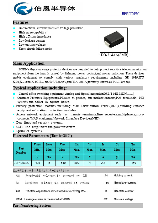
Features◆ Bi-directional crowbar transient voltage protection ◆ High surge capability ◆ High off-state impedance ◆ Low leakage current ◆ Low on-state voltage ◆ Short-circuit failure modeDO-214AA(SMB)Main ApplicationBORN’s thyristor surge protector devices are degsn ied to help protect sensitive telecommunication equipment from the hazards caused by lighning ,power contact,and power induction. These devices enable equipment to comply with various regulatory requirements including GR 1089,ITU K.20,K.21and K.45,IEC 60950,UL 60950,and TIA-968-A(formerly known as FCC Part 68).Typical application including:● Central office switching equipment. Analog and digital linecards(xDSL,T1/E1,ISDN……)● Customer Premises Equipment(CPE)such as phones, fax machines,modems,POS terminals, PBXsystems and caller ID adjunct boxes.● Primary protection modules including Main Distribution Frames(M DF),building entranceequipment and station protection modules.● Access network equipment such as remote terminals,line repeaters,multiplexers,cross-connects,WAN equipment,Network Int erface Devices(NID). ● Data lines and security systems.● CATV line amplifiers and power inserters. ● Sprinkler systems.Electrcal Parameters (Tamb=25℃)Part NumberV DRMI DRMV BOI BOV TI TC O`I HMin.Max.Max.Max.Max.Max.Max.Min.VuAVmAVApFmA BEP 4200SC400554080042.245150Eletrical CharacteristicsV DRMS t a nd -o ff v o l tag e,is m ea sur ed a t ID RM I HHolding current.V BOB r e a ko v e r v o l tag e,is m ea sur ed a t 100V/μs. I BOBreadover current.C OOff-state capacitance ismeasured in V DC =2V@1M HZ .I TON-state currentI DRM Leakage current,is measured at VDRM.V TOn-state voltage.Part Numbering SystemBEP 00SCBEP 00SC(A)(B)(C)(D)(A) SH’s Semiconductor Surge Arrester(B) Series:0080,0300…3500,3800,4200etc. (C) Pake:SMB(DO-214AA)(D) Rating Sure V oltage:C:6KV(10/700μs )Electrical Characteristics CurvesFigure1 V-I CharacteristicsFigure2 tr x td Pulse Wave-formFigure 3 Normalized V S Change versus Figure 4 Normalized DC Holding Current Junction TemperatureBEP 00SCThermal ConsiderationsPackage DO-214AA/SMBSymbolParameterValueUnitT J Operating Junction Temperature -40 to +150℃T S Storage Temperature Range -40 to +150℃R θJAJunction to Ambient on printed circuit90℃/WBEP 00SCDimensionInches Millimeters M IN M AX M INM AX A 0.134 0.155 3.40 3.94 B 0.205 0.22 5.21 5.59 C 0.075 0.083 1.90 2.11 D 0.166 0.185 4.22 4.70 E 0.036 0.056 0.91 1.42 F0.073 0.087 1.85 2.2 G 0.002 0.008 0.05 0.20 H 0.077 0.094 1.95 2.40 J0.043 0.053 1.09 1.35 K 0.008 0.014 0.20 0.35 L0.0390.0490.991.24Solder Reflow Recommendations●Recommended reflow methods: IR, vapor phase oven, hot air oven, wave solder. ●The device can be exposed to a maximumtemperature of 265°C for 10 seconds. ●Devices can be cleaned using standard industry methods and solvents.Notes: If reflow temperatures exceed therecommended profile, devices may not meet the performance requirements.Product Dimensions.079 (2.0)。
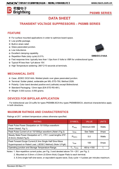

MECHANICAL DATACase: SMB (DO-214AA)Molding compound meets UL 94 V-0 flammability rating Base P/N-E3 - RoHS-compliant, commercial gradeBase P/N-M3 - halogen-free, RoHS-compliant, commercial gradeBase P/NHE3_X - RoHS-compliant and AEC-Q101 qualified Base P/NHM3_X - halogen-free, RoHS-compliant, and AEC-Q101 qualified(“_X” denotes revision code e.g. A, B, ..... and only available for 250 V to 540 V type)Terminals: matte tin plated leads, solderable per J-STD-002 and JESD 22-B102E3, M3, HE3, and HM3 suffix meets JESD 201 class 2 whisker testPolarity: for uni-directional types the band denotes cathode end, no marking on bi-directional typesNotes(1) Non-repetitive current pulse, per fig. 3 and derated above T A= 25 °C per fig. 2 (2) Mounted on 0.2" x 0.2" (5.0 mm x 5.0 mm) copper pads to each terminalFEATURES• Low profile package• Ideal for automated placement • Glass passivated chip junction• Available in uni-directional and bi-directional • 600 W peak pulse power capability with a 10/1000 μs waveform, repetitive rate (duty cycle): 0.01 %• Excellent clamping capability • Very fast response time• Low incremental surge resistance• Meets MSL level 1, per J-STD-020, LF maximum peak of 260 °C• AEC-Q101 qualified available- Automotive ordering code: base P/NHE3 or P/NHM3(1) Pulse test: t p 50 ms(2) Surge current waveform per fig. 3 and derate per fig. 2(3) For bi-directional types with V WM of 10 V and less, the I D limit is doubled(4) All terms and symbols are consistent with ANSI/IEEE CA62.35(5) V F = 3.5 V at I F = 50 A (uni-directional only)RATINGS AND CHARACTERISTICS CURVES (T A = 25 °C unless otherwise noted)1001011007550250.10.1 µs 1.0 µs 10 µs 100 µs 1.0 ms 10 ms0 25 50 75 100125 150 175 200t d - Pulse Width (s) TJ - Initial Temperature (°C) Fig. 1 - Peak Pulse Power Rating Curve Fig. 2 - Pulse Power or Current vs. Initial Junction TemperatureFig. 3 - Pulse Waveform Fig. 5 - Typical Transient Thermal Impedance Fig. 4 - Typical Junction Capacitance Fig. 6 - Maximum Non-Repetitive Peak Forward Surge Current PPPM-PeakPulsePower(kW)PeakPulsePower(PPP)orCurrent(IPP)DeratinginPercentage,%。
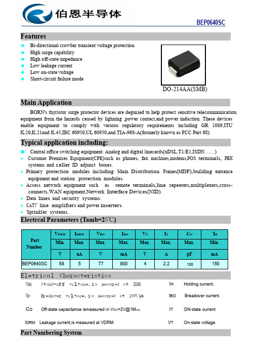
Features◆ Bi-directional crowbar transient voltage protection ◆ High surge capability ◆ High off-state impedance ◆ Low leakage current ◆ Low on-state voltage ◆ Short-circuit failure modeDO-214AA(SMB)Main ApplicationBORN’s thyristor surge protector devices are degsn ied to help protect sensitive telecommunication equipment from the hazards caused by lighning ,power contact,and power induction. These devices enable equipment to comply with various regulatory requirements including GR 1089,ITU K.20,K.21and K.45,IEC 60950,UL 60950,and TIA-968-A(formerly known as FCC Part 68).Typical application including:● Central office switching equipment. Analog and digital linecards(xDSL,T1/E1,ISDN……)● Customer Premises Equipment(CPE)such as phones, fax machines,modems,POS terminals, PBXsystems and caller ID adjunct boxes.● Primary protection modules including Main Distribution Frames(M DF),building entranceequipment and station protection modules.● Access network equipment such as remote terminals,line repeaters,multiplexers,cross-connects,WAN equipment,Network Int erface Devices(NID). ● Data lines and security systems.● CATV line amplifiers and power inserters. ● Sprinkler systems.Electrcal Parameters (Tamb=25℃)Part NumberV DRMI DRMV BOI BOV TI TC O`I H Min.Max.Max.Max.Max.Max.Max.Min.VuAVmAVApFmA BEP 0640SC5857780042.2100150Eletrical CharacteristicsV DRMS t a nd -o ff v o l tag e,is m ea sur ed a t ID RM I HHolding current.V BOB r e a ko v e r v o l tag e,is m ea sur ed a t 100V/μs. I BOBreadover current.C OOff-state capacitance ismeasured in V DC =2V@1M HZ .I TON-state currentI DRM Leakage current,is measured at VDRM.V TOn-state voltage.Part Numbering SystemBEP 0640SCBEP 0640SC(A)(B)(C)(D)(A) SH’s Semiconductor Surge Arrester(B) Series:0080,0300…3500,3800,4200etc. (C) Pake:SMB(DO-214AA)(D) Rating Sure V oltage:C:6KV(10/700μs )Electrical Characteristics CurvesFigure1 V-I CharacteristicsFigure2 tr x td Pulse Wave-formFigure 3 Normalized V S Change versus Figure 4 Normalized DC Holding Current Junction TemperatureBEP 0640SCThermal ConsiderationsPackage DO-214AA/SMBSymbolParameterValueUnitT J Operating Junction Temperature -40 to +150℃T S Storage Temperature Range -40 to +150℃R θJAJunction to Ambient on printed circuit90℃/WBEP 0640SCDimensionInches Millimeters M IN M AX M INM AX A 0.134 0.155 3.40 3.94 B 0.205 0.22 5.21 5.59 C 0.075 0.083 1.90 2.11 D 0.166 0.185 4.22 4.70 E 0.036 0.056 0.91 1.42 F0.073 0.087 1.85 2.2 G 0.002 0.008 0.05 0.20 H 0.077 0.094 1.95 2.40 J0.043 0.053 1.09 1.35 K 0.008 0.014 0.20 0.35 L0.0390.0490.991.24Solder Reflow Recommendations●Recommended reflow methods: IR, vapor phase oven, hot air oven, wave solder. ●The device can be exposed to a maximumtemperature of 265°C for 10 seconds. ●Devices can be cleaned using standard industry methods and solvents.Notes: If reflow temperatures exceed therecommended profile, devices may not meet the performance requirements.Product Dimensions.079 (2.0)。
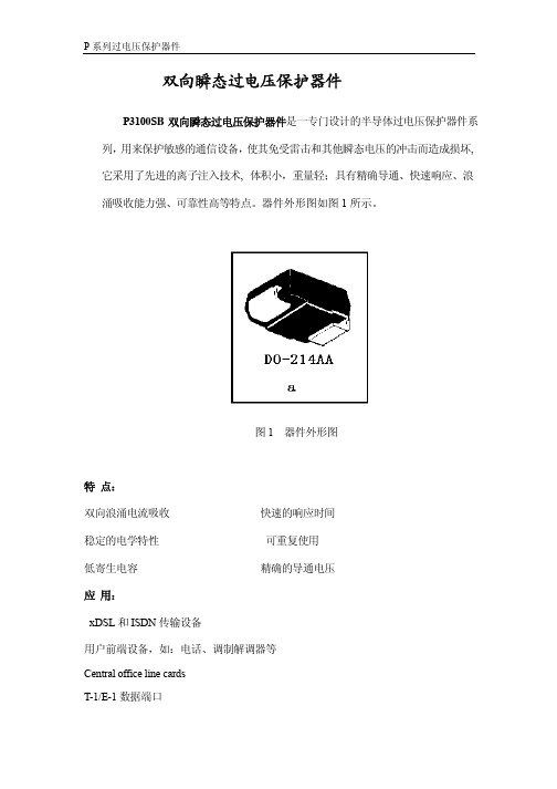
双向瞬态过电压保护器件
P3100S B双向瞬态过电压保护器件是一专门设计的半导体过电压保护器件系列,用来保护敏感的通信设备,使其免受雷击和其他瞬态电压的冲击而造成损坏,它采用了先进的离子注入技术,体积小,重量轻;具有精确导通、快速响应、浪涌吸收能力强、可靠性高等特点。
器件外形图如图1所示。
图1 器件外形图
特点:
双向浪涌电流吸收快速的响应时间
稳定的电学特性可重复使用
低寄生电容精确的导通电压
应用:
xDSL和ISDN传输设备
用户前端设备,如:电话、调制解调器等
Central office line cards
T-1/E-1数据端口
PBX 和其它交换设备
数据线保护
P3100S B 双向瞬态过电压保护器件的器件等效结构和 I-V 特性曲线如图 2和图 3示。
图 2 器件等效结构 图3 器件I-V 特性曲线
P3100S B 双向瞬态过电压保护器件的电学参数: V DRM I DRM V BO I BO V T I T I H Co
I PP Max. Max. Min.Max.Max.Max.Min.Max.
A Part Number
V µA V mA mA V A
mA pF A P3100S B 275 10 350 150 800 5 1 100 40 100(10/560us)
注:1、DO-214AA 封装
2、寄生电容Co 是在1MHz ,2V 偏置条件下产品的最大测量值。
标示说明:0S B
生产日期 (例如:0421表示 2004年第 21周生产)
包 装:2500PCS/REEL
封装形式:。
Page 1 of 4Features◆ Bi-directional crowbar transient voltage protection ◆ High surge capability ◆ High off-state impedance ◆ Low leakage current ◆ Low on-state voltage ◆ Short-circuit failure modeDO-214AA(SMB)Main ApplicationELA ’s thyristor surge protector devices are designed to help protect sensitive telecommunication equipment from the hazards caused by lighning ,power contact,and power induction. These devices enable equipment to comply with various regulatory requirements including GR 1089,ITU K.20,K.21and K.45,IEC 60950,UL 60950,and TIA-968-A(formerly known as FCC Part 68).Typical application including:● Central office switching equipment. Analog and digital linecards(xDSL,T1/E1,ISDN……)● Customer Premises Equipment(CPE)such as phones, fax machines,modems,POSterminals, PBX systems and caller ID adjunct boxes. ● Primary protection modules including Main Distribution Frames(M DF),building entrance equipment and station protection modules.● Access network equipment such as remoteterminals,line repeaters,multiplexers,cross-connects,WAN equipment,Network Int erface Devices(NID).● Data lines and security systems.● CATV line amplifiers and power inserters. ● Sprinkler systems.Electrcal Parameters (Tamb=25℃)Part NumberV DRMI DRMV BOI BOV TI TC O`I H Min.Max.Max.Max.Max.Max.Max.Min.VuAVmAVApFmABEP 3100SB275535080042.245150Eletrical CharacteristicsV DRMS t a nd -o ff v o l tag e,is m ea sur ed a t ID RM I HHolding current.V BOB r e a ko v e r v o l tag e,is m ea sur ed a t 100V/μs. I BOBreadover current.C OOff-state capacitance ismeasured in V DC =2V@1M HZ .I TON-state currentPage 2 of 4I DRM Leakage current,is measured at VDRM.V T On-state voltage.Part Numbering SystemBEP 3100SB(A)(B)(C)(D)(A) SH’s Semiconductor Surge Arrester(B) Series:0080,0300…3500,3800,4200etc. (C) Pake:SMB(DO-214AA)(D) Rating Sure V oltage:B:4KV(10/700μs )Electrical Characteristics CurvesFigure1 V-I CharacteristicsFigure2 tr x td Pulse Wave-formFigure 3 Normalized V S Change versus Figure 4 Normalized DC Holding Current Junction TemperatureBEP 3100SBThermal ConsiderationsPackage DO-214AA/SMBSymbolParameterValueUnitT J Operating Junction Temperature -40 to +150℃T S Storage Temperature Range -40 to +150℃R θJAJunction to Ambient on printed circuit90℃/WSolder Reflow Recommendations●Recommended reflow methods: IR, vapor phase oven, hot air oven, wave solder. ●The device can be exposed to a maximumtemperature of 265°C for 10 seconds. ●Devices can be cleaned using standard industry methods and solvents.Notes: If reflow temperatures exceed therecommended profile, devices may not meet the performance requirements.DimensionInches Millimeters M IN M AX M INM AX A 0.134 0.155 3.40 3.94 B 0.205 0.22 5.21 5.59 C 0.075 0.083 1.90 2.11 D 0.166 0.185 4.22 4.70 E 0.036 0.056 0.91 1.42 F0.073 0.087 1.85 2.2 G 0.002 0.008 0.05 0.20 H 0.077 0.094 1.95 2.40 J0.043 0.053 1.09 1.35 K 0.008 0.014 0.20 0.35 L0.0390.0490.991.24BEP 3100SBProduct Dimensions.079 (2.0)。
•Electrically isolated base plate•Available up to 1200 V RRM /V DRM•High dynamic characteristics•Wide choice of circuit configurations•Simplified mechanical design and assembly•UL E78996 approved•Material categorization: for definitions of complianceplease see /doc?99912DESCRIPTIONThe VS-P100 series of integrated power circuits consists of power thyristors and power diodes configured in a single package. With its isolating base plate, mechanical designs are greatly simplified giving advantages of cost reduction and reduced size.Applications include power supplies, control circuits andbattery chargers.ELECTRICAL SPECIFICATIONS PRIMARY CHARACTERISTICS I O 25 ATypeModules - thyristor, standard Package PACE-PAK (D-19)PACE-PAK (D-19)MAJOR RATINGS AND CHARACTERISTICSSYMBOLCHARACTERISTICS VALUES UNITS I O85 °C 25A I TSM50 Hz 357A 60 Hz 375I 2t50 Hz 637A 2s 60 Hz 580I 2√t6365A 2√s V DRM , V RRM400 to 1200V V ISOL2500V T JRange -40 to +125°C T Stg -40 to +125°CVOLTAGE RATINGSTYPE NUMBERV RRM /V DRM , MAXIMUM REPETITIVE PEAK REVERSE AND PEAK OFF-STATE VOLTAGE V V RSM , MAXIMUM NON-REPETITIVE PEAK REVERSE VOLTAGE V I RRM MAXIMUM AT T J MAXIMUM mAVS-P101, VS-P121, VS-P13140050010VS-P102, VS-P122, VS-P132600700VS-P103, VS-P123, VS-P133800900VS-P103, VS-P124, VS-P13410001100VS-P105, VS-P125, VS-P135********25 85Maximum peak, one-cycle non-repetitive on-state or forward current I TSM,I FSMNo voltagereappliedSinusoidal half wave,initial T J = T J maximum357A t = 8.3 ms375t = 10 ms100 % VRRMreapplied300 t = 8.3 ms315Maximum I2t for fusing I2t t = 10 ms No voltagereapplied637A2s t = 8.3 ms580t = 10 ms100 % VRRMreapplied450t = 8.3 ms410Maximum I2√t for fusing I2√t t = 0.1 ms to 10 ms, no voltage reappliedI2t for time tx = I2√t · √tx6365A2√sMaximum value of threshold voltage V T(TO)T J = 125 °C0.82V Maximum level value of on-state sloperesistancer t1T J = 125 °C, average power = V T(TO) x I T(AV) + r t + (I T(RMS))212mΩMaximum on-state voltage drop V TM I TM = π x I T(AV)T J = 25 °C 1.35V Maximum forward voltage drop V FM I FM = π x I F(AV)T J = 25 °C 1.35VMaximum non-repetitive rate of rise of turned-on current dI/dtT J = 125 °C from 0.67 V DRMI TM = π x I T(AV), I g = 500 mA, t r < 0.5 μs, t p > 6 μs200A/μsMaximum holding current I H T J = 25 °C anode supply = 6 V, resistive load, gate open130mA Maximum latching current I L T J = 25 °C anode supply = 6 V, resistive load250BLOCKINGPARAMETERS YMBOL TES TCONDITIONS VALUES UNITS Maximum critical rate of rise of off-statevoltagedV/dt T J = 125 °C, exponential to 0.67 V DRM gate open200V/μsMaximum peak reverse and off-state leakage current at V RRM, V DRM I RRM,I DRMT J = 125 °C, gate open circuit10mAMaximum peak reverse leakage current I RRM T J = 25 °C100μARMS isolation voltage V ISOL 50 Hz, circuit to base, all terminals shorted,T J = 25 °C, t = 1 s2500VTRIGGERINGPARAMETER SYMBOL TEST CONDITIONS VALUES UNITS Maximum peak gate power P GM8W Maximum average gate power P G(AV)2Maximum peak gate current I GM2A Maximum peak negative gate voltage-V GM10VMaximum gate voltage required to trigger V GTT J = -40 °CAnode supply =6 V resistive load 3VT J = 25 °C2 T J = 125 °C1Maximum gate current required to trigger I GT T J = -40 °C90mA T J = 25 °C60T J = 125 °C35Maximum gate voltage that will not trigger V GDT J = 125 °C, rated V DRM applied 0.2VMaximum gate current that will not trigger I GD2mANote(1) A mounting compound is recommended and the torque should be checked after a period of 3 hours to allow for the spread of the compoundFig. 1 - Current Ratings Nomogram (1 Module Per Heatsink)Fig. 2 - On-State Power Loss Characteristics Fig. 3 - On-State Power Loss Characteristics junction to case per junctionR thJC DC operation 2.24K/W Maximum thermal resistance,case to heatsinkR thCS Mounting surface, smooth and greased 0.10Mounting torque, base to heatsink (1)4Nm Approximate weight58g 2.0oz.Case style PACE-PAK (D-19)Fig. 4 - Current Ratings Characteristics Fig. 5 - On-State Voltage Drop Characteristics Fig. 6 - Maximum Non-Repetitive Surge CurrentFig. 7 - Maximum Non-Repetitive Surge CurrentFig. 8 - Thermal Impedance Z thJC CharacteristicsFig. 9 - Gate Characteristics ORDERING INFORMATION TABLENote(1) To complete code refer to Voltage Ratings table, i.e.: for 600 V P10.W complete code is P102WCODING (1)CIRCUIT DESCRIPTIONCIRCUIT CONFIGURATION CODE BASIC SERIES WITH VOLTAGE SUPPRESSION WITH FREEWHEELING DIODE WITH BOTH VOLTAGE SUPPRESSION AND FREEWHEELING DIODE Single phase, hybrid bridgecommon cathode0P10.P10.K P10.W P10.KW Single phase, hybrid bridgedoubler connection2P12.P12.K --Single phase, all SCR bridge 3P13.P13.K --LINKS TO RELATED DOCUMENTSDimensions /doc?95335V ishay Intertechnology, Inc., its affiliates, agents, and employees, and all persons acting on its or their behalf (collectively,“Vishay”), disclaim any and all liability for any errors, inaccuracies or incompleteness contained in any datasheet or in any other disclosure relating to any product.Vishay makes no warranty, representation or guarantee regarding the suitability of the products for any particular purpose or the continuing production of any product. To the maximum extent permitted by applicable law, Vishay disclaims (i) any and all liability arising out of the application or use of any product, (ii) any and all liability, including without limitation special, consequential or incidental damages, and (iii) any and all implied warranties, including warranties of fitness for particular purpose, non-infringement and merchantability.Statements regarding the suitability of products for certain types of applications are based on Vishay's knowledge of typical requirements that are often placed on Vishay products in generic applications. Such statements are not binding statements about the suitability of products for a particular application. It is the customer's responsibility to validate that a particular product with the properties described in the product specification is suitable for use in a particular application. Parameters provided in datasheets and / or specifications may vary in different applications and performance may vary over time. All operating parameters, including typical parameters, must be validated for each customer application by the customer's technical experts. Product specifications do not expand or otherwise modify Vishay's terms and conditions of purchase, including but not limited to the warranty expressed therein.Hyperlinks included in this datasheet may direct users to third-party websites. These links are provided as a convenience and for informational purposes only. Inclusion of these hyperlinks does not constitute an endorsement or an approval by Vishay of any of the products, services or opinions of the corporation, organization or individual associated with the third-party website. Vishay disclaims any and all liability and bears no responsibility for the accuracy, legality or content of the third-party website or for that of subsequent links.Except as expressly indicated in writing, Vishay products are not designed for use in medical, life-saving, or life-sustaining applications or for any other application in which the failure of the Vishay product could result in personal injury or death. Customers using or selling Vishay products not expressly indicated for use in such applications do so at their own risk. Please contact authorized Vishay personnel to obtain written terms and conditions regarding products designed for such applications. No license, express or implied, by estoppel or otherwise, to any intellectual property rights is granted by this document or by any conduct of Vishay. Product names and markings noted herein may be trademarks of their respective owners.© 2021 VISHAY INTERTECHNOLOGY, INC. ALL RIGHTS RESERVED。
Features/Benefits• Compliant with ESA specifications 3401/072• Ultra-light weight• Solid fully machined aluminium alloy material• Non MagneticTypical Applications• Space equipment• Satellites harnesses• Avionics / MilitarySpecificationHigh performance Backshell ESA qualified, for space applications.Compliant to ESCC specifications 3401/072 Lightweight Accessories for rectangular connectors 3401/001 and 3401/002. Compatible with ESCC 3401/022 accessories.Suitable for use in Space, and high performance military/aerospace applications: Board to Cable or Cable to Cable applications. Sizes available:E, A, B, C, D and F.Outlets:Straight saddle clampStraight cylindricalStraight cylindrical for EMI applicationStraight elliptical45° elliptical90° cylindricalCharacteristicsCHARACTERISTIC SPECIFICATIONOperating temperature range -55 / +125 °CStorage temperature range -55 / +125 °CResidual Magnetism Level 200 Gamma max.Quality LevelFlying Model: Code 3401 - ESA / ESCC specification. Qualification reviewed every 2 years.Engineering Model: code FR022 - C&K specification.OptionsUniversal male screwlock with “slotted” or “hexagonal hole” head screw (be ordered separately).PackagingIndividual packaging.Traceability associated as per ESA/ESCC specifications.COMPONENT MATERIAL FINISHShell Aluminium alloy 6061-T6 Code A174: 25.4 µm min. electroless NickelNo code or FR172: 0.7 µm min. Gold over 25.4 µm min. electroless NickelScrews Brass 0.7 µm Gold over 1 µm min. Cu Gasket Silicone conductive elastomer NoneDescription and Part NumbersSize A ±0.2 B ±0.15 C ±0.13 D ±0.50 ØE ±0.15 ØF ±0.15 G ±0.50 Weight (grams)E 30.68 12.50 24.99 40.6 7.009.0025.4 6.5 A 39.01 12.50 33.32 49.0 10.00 12.00 25.4 10 B 52.91 12.50 47.04 62.7 10.50 12.50 25.4 13.5 C 69.19 12.50 63.50 79.2 10.50 12.50 25.4 18 D 66.80 15.30 61.11 76.7 13.30 15.30 25.4 23 F69.30 17.30 63.5079.915.30 17.3035.428Configuration Sizes E-A-B-C-DConfiguration Size FDetail A-ADetail B-BRight Outlet(Our design accepts right or left mounting)Description and Part NumbersSize A ±0.2 B ±0.15 C ±0.13 D ±0.50 ØE ±0.15 ØF ±0.15 G ±0.50 Weight (grams)E 30.68 12.50 24.99 40.6 7.009.0025.4 6.5 A 39.01 12.50 33.32 49.0 10.00 12.00 25.4 10 B 52.91 12.50 47.04 62.7 10.50 12.50 25.4 13.5 C 69.19 12.50 63.50 79.2 10.50 12.50 25.4 18 D 66.80 15.30 61.11 76.7 13.30 15.30 25.4 23 F69.30 17.30 63.5079.915.30 17.3035.428Left Outlet(Our design accepts right or left mounting) Configuration Sizes E-A-B-C-DConfiguration Size FDetail A-ADetail B-BSize A ±0.2 B ±0.15 C ±0.13 D ±0.20 E ±0 .15 Weight (grams) E 30.68 12.50 24.99 7.00 9.00 6.5 A 39.01 12.50 33.32 10.00 12.00 8.5 B 52.91 12.50 47.04 10.50 12.50 11.5 C 69.19 12.50 63.50 10.50 12.50 13.5 D 66.80 15.30 61.11 13.30 15.30 14.5 F69.3017.3063.5015.3017.3016.5Straight Cable OutletDetail A-ADetail B-BConfiguration Sizes E-A-B-C-DConfiguration Size FSize A ±0.2 B ±0.15 C ±0.13 D ±0.38 E ±0 .15 Weight (grams)E 30.68 12.50 24.99 12.70 9.50 8 A 39.01 12.50 33.32 15.87 9.50 13 B 52.91 12.50 47.04 19.05 9.50 18 C 69.19 12.50 63.50 25.40 9.50 23 D 66.80 15.30 61.11 22.22 12.30 28 F69.3017.3063.5032.0014.3033Detail A-AConfiguration Size FConfiguration Sizes E-A-B-C-DDetail B-BUltra-Elliptical Band TerminationSize A ±0.2 B ±0.15 C ±0.13 D ±0.38 E ±0 .15 Weight (grams) E 30.68 12.50 24.99 12.70 9.50 10 A 39.01 12.50 33.32 15.87 9.50 14 B 52.91 12.50 47.04 19.05 9.50 20 C 69.19 12.50 63.50 25.40 9.50 26 D 66.80 15.30 61.11 22.22 12.30 33 F69.3017.3063.5029.0014.3040Right Outlet(Our design accepts right or left mounting) Detail A-ADetail B-BConfiguration Size F F ViewConfiguration Sizes E-A-B-C-DSize A ±0.2 B ±0.15 C ±0.13 D ±0.38 E ±0 .15 Weight (grams) E 30.68 12.50 24.99 12.70 9.50 10 A 39.01 12.50 33.32 15.87 9.50 14 B 52.91 12.50 47.04 19.05 9.50 20 C 69.19 12.50 63.50 25.40 9.50 26 D 66.80 15.30 61.11 22.22 12.30 33 F69.3017.3063.5029.0014.3040Left Outlet(Our design accepts right or left mounting) Detail A-ADetail B-BConfiguration Size F Configuration Sizes E-A-B-C-DF ViewDescription and Part NumbersSize A ±0.2 B ±0.15 C ±0.13 D ±0.30 E ±0 .25 F ±0 .50 Weight (grams) E 30.68 12.50 24.99 9.50 9.50 66.75 15.5 A 39.01 12.50 33.32 18.10 9.50 66.75 19 B 52.91 12.50 47.04 25.40 9.50 68.35 23 C 69.19 12.50 63.50 34.90 9.50 68.35 29 D 66.80 15.30 61.11 35.70 11.90 68.35 33 F69.3017.3063.5047.0013.9068.3537Saddle Clamp for Straight ReliefDetail A-ADetail B-BConfiguration Size FConfiguration Sizes E-A-B-C-DSize A ±0.2 B ±0.15 C ±0.13 Weight (grams)E 30.68 12.50 24.99 8 A 39.01 12.50 33.32 10 B 52.91 12.50 47.04 14 C 69.19 12.50 63.50 20 D 66.80 15.30 61.11 26 F69.3017.3063.5030Detail A-ADetail B-BConfiguration Size FConfiguration Sizes E-A-B-C-DShorting CanFinishSizeESA/ESCC Quality Level FR022 Quality Level DescriptionP/NDescriptionP/NElectroless NickelE 340107261B NMBA-A174 C115366-2637D DE-BCKS-10-NMB-A174-FR022 C115366-2637B A340107262B NMBA-A174 C115366-2638D DA-BCKS-10-NMB-A174-FR022 C115366-2638B B 340107263B NMBA-A174 C115366-2639D DB-BCKS-10-NMB-A174-FR022 C115366-2639B C 340107264B NMBA-A174 C115366-2640D DC-BCKS-10-NMB-A174-FR022C115366-2640B D 340107265B NMBA-A174 C115366-2641D DD-BCKS-10-NMB-A174-FR022 C115366-2641B F 340107280B NMB-A174 C115366-2695D DF-BCKS-10-NMB-A174-FR022 C115366-2695B GoldE 340107261B NMBA C115366-2637C DE-BCKS-10-NMB-FR172-FR022 C115366-2637A A 340107262B NMBA C115366-2638C DA-BCKS-10-NMB-FR172-FR022 C115366-2638A B 340107263B NMBA C115366-2639C DB-BCKS-10-NMB-FR172-FR022 C115366-2639A C 340107264B NMBA C115366-2640C DC-BCKS-10-NMB-FR172-FR022 C115366-2640A D 340107265B NMBA C115366-2641C DD-BCKS-10-NMB-FR172-FR022 C115366-2641A F340107280B NMBC115366-2695CDF-BCKS-10-NMB-FR172-FR022C115366-2695ASize A ±0.2 B ±0.15 C ±0.13 Weight (grams)E 30.68 12.50 24.99 8 A 39.01 12.50 33.32 10 B 52.91 12.50 47.04 14 C 69.19 12.50 63.50 20 D 66.80 15.30 61.11 26 F69.3017.3063.5030Extra Shorting CanDetail A-ADetail B-BConfiguration Size FConfiguration Sizes E-A-B-C-DDescription and Part NumbersSize A ±0.25 B ±0.25 C ±0.13 D ±0.30 E ±0 .25 F +0.05/0 Weight (grams) E 35.03 15.98 24.99 32.70 6.73 8.35 21 A 43.36 15.98 33.32 32.70 9.90 8.35 26 B 57.25 15.98 47.04 38.30 10.54 8.35 30 C 73.53 15.98 63.50 38.30 10.54 8.35 35 D71.1418.7561.1138.3013.338.3540Straight Cable Outlet for EMI Application(EMI performances linked to the design of the harness)Front Mounting OnlyAccessoriesFR022 Quality Level Slotted Head Screw Description P/N Description P/N340102287B NMB C115366-2408C D115440-0165-FR022 C115440-0165ADescription P/N Description P/N340102289B NMB C115366-2410C D115440-0167-FR022 C115440-0167A For the complete range of accessories and details, consult our D-Sub accessories datasheet.。
Features◆ Bi-directional crowbar transient voltage protection ◆ High surge capability ◆ High off-state impedance ◆ Low leakage current ◆ Low on-state voltage ◆ Short-circuit failure modeDO-214AA(SMB)Main ApplicationBORN’s thyristor surge protector devices are degsn ied to help protect sensitive telecommunication equipment from the hazards caused by lighning ,power contact,and power induction. These devices enable equipment to comply with various regulatory requirements including GR 1089,ITU K.20,K.21and K.45,IEC 60950,UL 60950,and TIA-968-A(formerly known as FCC Part 68).Typical application including:● Central office switching equipment. Analog and digital linecards(xDSL,T1/E1,ISDN……)● Customer Premises Equipment(CPE)such as phones, fax machines,modems,POS terminals, PBXsystems and caller ID adjunct boxes.● Primary protection modules including Main Distribution Frames(M DF),building entranceequipment and station protection modules.● Access network equipment such as remote terminals,line repeaters,multiplexers,cross-connects,WAN equipment,Network Int erface Devices(NID). ● Data lines and security systems.● CATV line amplifiers and power inserters. ● Sprinkler systems.Electrcal Parameters (Tamb=25℃)Part NumberV DRMI DRMV BOI BOV TI TC O`I H Min.Max.Max.Max.Max.Max.Max.Min.VuAVmAVApFmA BEP 0300SC2554080042.210025Eletrical CharacteristicsV DRMS t a nd -o ff v o l tag e,is m ea sur ed a t ID RM I HHolding current.V BOB r e a ko v e r v o l tag e,is m ea sur ed a t 100V/μs. I BOBreadover current.C OOff-state capacitance ismeasured in V DC =2V@1M HZ .I TON-state currentI DRM Leakage current,is measured at VDRM.V TOn-state voltage.Part Numbering SystemBEP 0300SCBEP 0300SC(A)(B)(C)(D)(A) SH’s Semiconductor Surge Arrester(B) Series:0080,0300…3500,3800,4200etc. (C) Pake:SMB(DO-214AA)(D) Rating Sure V oltage:C:6KV(10/700μs )Electrical Characteristics CurvesFigure1 V-I CharacteristicsFigure2 tr x td Pulse Wave-formFigure 3 Normalized V S Change versus Figure 4 Normalized DC Holding Current Junction TemperatureBEP 0300SCThermal ConsiderationsPackage DO-214AA/SMBSymbolParameterValueUnitT J Operating Junction Temperature -40 to +150℃T S Storage Temperature Range -40 to +150℃R θJAJunction to Ambient on printed circuit90℃/WBEP 0300SCDimensionInches Millimeters M IN M AX M INM AX A 0.134 0.155 3.40 3.94 B 0.205 0.22 5.21 5.59 C 0.075 0.083 1.90 2.11 D 0.166 0.185 4.22 4.70 E 0.036 0.056 0.91 1.42 F0.073 0.087 1.85 2.2 G 0.002 0.008 0.05 0.20 H 0.077 0.094 1.95 2.40 J0.043 0.053 1.09 1.35 K 0.008 0.014 0.20 0.35 L0.0390.0490.991.24Solder Reflow Recommendations●Recommended reflow methods: IR, vapor phase oven, hot air oven, wave solder. ●The device can be exposed to a maximumtemperature of 265°C for 10 seconds. ●Devices can be cleaned using standard industry methods and solvents.Notes: If reflow temperatures exceed therecommended profile, devices may not meet the performance requirements.Product Dimensions.079 (2.0)。
Features
◆ Bi-directional crowbar transient voltage protection ◆ High surge capability ◆ High off-state impedance ◆ Low leakage current ◆ Low on-state voltage ◆ Short-circuit failure mode
DO-214AA(SMB)
Main Application
BORN’s thyristor surge protector devices are degsn ied to help protect sensitive telecommunication equipment from the hazards caused by lighning ,power contact,and power induction. These devices enable equipment to comply with various regulatory requirements including GR 1089,ITU K.20,K.21and K.45,IEC 60950,UL 60950,and TIA-968-A(formerly known as FCC Part 68).
Typical application including:
● Central office switching equipment. Analog and digital linecards(xDSL,T1/E1,ISDN……)
● Customer Premises Equipment(CPE)such as phones, fax machines,modems,POS terminals, PBX
systems and caller ID adjunct boxes.
● Primary protection modules including Main Distribution Frames(M DF),building entrance
equipment and station protection modules.
● Access network equipment such as remote terminals,line repeaters,multiplexers,cross-connects,WAN equipment,Network Int erface Devices(NID). ● Data lines and security systems.
● CATV line amplifiers and power inserters. ● Sprinkler systems.
Electrcal Parameters (Tamb=25℃)
Part Number
V DRM
I DRM
V BO
I BO
V T
I T
C O
`I H Min.
Max.
Max.
Max.
Max.
Max.
Max.
Min.
V
uA
V
mA
V
A
pF
mA BEP 3100SC
275
5
350
800
4
2.2
65
150
Eletrical Characteristics
V DRM
S t a nd -o ff v o l tag e,is m ea sur ed a t ID RM I H
Holding current.
V BO
B r e a ko v e r v o l tag e,is m ea sur ed a t 100V/μs. I BO
Breadover current.
C O
Off-state capacitance ismeasured in V DC =2V@1M HZ .
I T
ON-state current
I DRM Leakage current,is measured at VDRM.
V T
On-state voltage.
Part Numbering System
BEP 3100SC
BEP 3100
S
C
(A)
(B)
(C)
(D)
(A) SH’s Semiconductor Surge Arrester
(B) Series:0080,0300…3500,3800,4200etc. (C) Pake:SMB(DO-214AA)
(D) Rating Sure V oltage:C:6KV(10/700μs )
Electrical Characteristics Curves
Figure1 V-I Characteristics
Figure2 tr x td Pulse Wave-form
Figure 3 Normalized V S Change versus Figure 4 Normalized DC Holding Current Junction Temperature
BEP 3100SC
Thermal Considerations
Package DO-214AA/SMB
Symbol
Parameter
Value
Unit
T J Operating Junction Temperature -40 to +150
℃
T S Storage Temperature Range -40 to +150
℃
R θJA
Junction to Ambient on printed circuit
90
℃/W
BEP 3100SC
Dimension
Inches Millimeters M IN M AX M IN
M AX A 0.134 0.155 3.40 3.94 B 0.205 0.22 5.21 5.59 C 0.075 0.083 1.90 2.11 D 0.166 0.185 4.22 4.70 E 0.036 0.056 0.91 1.42 F
0.073 0.087 1.85 2.2 G 0.002 0.008 0.05 0.20 H 0.077 0.094 1.95 2.40 J
0.043 0.053 1.09 1.35 K 0.008 0.014 0.20 0.35 L
0.039
0.049
0.99
1.24
Solder Reflow Recommendations
●Recommended reflow methods: IR, vapor phase oven, hot air oven, wave solder. ●The device can be exposed to a maximum
temperature of 265°C for 10 seconds. ●Devices can be cleaned using standard industry methods and solvents.
Notes: If reflow temperatures exceed the
recommended profile, devices may not meet the performance requirements.
Product Dimensions
.079 (2.0)。