SCL-6系列超声流量计说明书(含60、62)
- 格式:pdf
- 大小:2.21 MB
- 文档页数:35

六通道超声波发生器使用说明书深圳己道科技有限公司目录1概述 (3)2功能部件 (3)2.1前面板 (3)2.2后面板 (4)3接口、功能及技术指标 (4)3.1环境接口 (4)3.2电气接口 (4)3.3结构尺寸 (6)4功能及技术指标 (6)4.1主要功能 (6)4.2技术指标 (6)5基本操作 (7)5.1显示 (7)5.2操作 (9)5.3开机、关机 (11)5.4外部急停使能 (11)5.5总启动、停止 (12)6使用规范 (12)7异常情况处理 (12)8技术支持 (12)1概述六通道超声波发生器(以下简称发生器)可同时输出6通道同频、不同相的超声波信号,具备自动扫频和频率追踪功能,在不同负载状态下6个换能器同时有效谐振,并且1组3个换能器之间相位可调。
发生器可以独立使用,通过面板元件来设置各项功能和参数。
本文介绍了发生器的功能部件,描述了发生器的使用方法。
2功能部件2.1前面板a.液晶显示器,数字化显示所有状态及参数;b.选择按钮,选中需要设置的参数;c.手轮,配合选择按钮设置参数;d.启动/停止按钮,启动或关闭超声信号输出;e.急停使能开关,使能或禁能外部急停信号;f.RS-485通信插座,连接上位机通信线;g.外控IO插座,连接防爆柜IO插头,内含振子类型选择和急停信号。
2.2后面板a.电源开关,接通或关断发生器总电源;b.电源插座,连接电源线;c.散热风扇1、2,排风口,冷却发生器内部元件;d.超声信号插座,输出A、B、C、D、E、F共六个通道的超声信号;e.超声信号接线柱,也是超声信号输出端,内部与超声信号插座并联,便于连接示波器或U型接线端子,红色接线柱为正极,黑色为负极。
3接口、功能及技术指标3.1环境接口a.供电电源:AC220V,50Hz,3000VA;b.环境温度:0℃-45℃;c.环境湿度:1%-95%,无凝露。
3.2电气接口a.电源插座采用带保险管座的三线品字插座,配2.5方的三芯电源线。
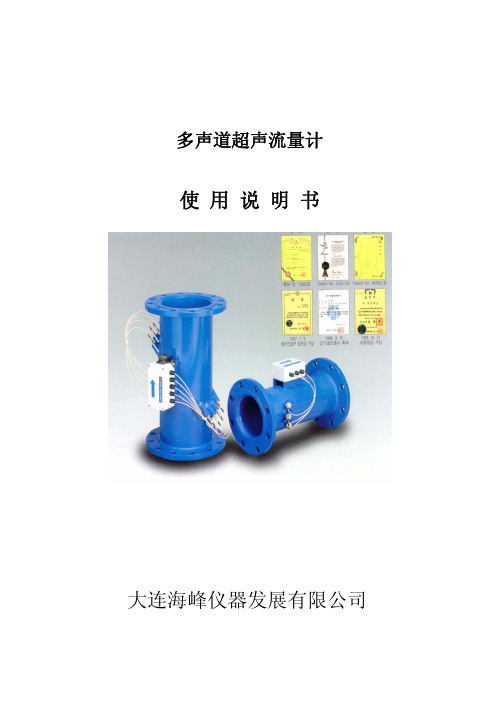
多声道超声流量计使用说明书大连海峰仪器发展有限公司目 录1多声道超声流量计简介 (1)1.1测量原理 (1)1.2产品特点 (1)1.3产品构成 (1)2技术参数 (2)2.1准确度等级 (2)2.2工作环境要求 (2)2.3流量计防护等级 (2)2.4显示参数 (2)2.5输出 (2)2.6控制器(二次表)外形尺寸及重量 (2)3流量计安装 (2)3.1测量管(一次表)安装 (3)3.2控制器(二次表)安装 (3)3.3仪表箱(LOP)的安装 (3)3.4现场仪表盘内部接线 (6)3.5主电缆安装 (6)3.6压力变送器安装 (8)3.7接地方法 (9)3.8排水泵安装 (11)4控制器外观及操作键 (12)4.1控制器外观 (12)4.2操作键 (12)5显示器(LCD) (12)6功能与编制程序 (13)6.1功能菜单设定(MEAS FUNCTION) (13)6.2时间设定(TIME FUNCTION) (15)6.3累积流量清零,停电记录清零,存储数据清零 (15)6.4密码设定 (16)6.5查看累积流量,停电记录,错误编码 (16)6.6查看STAT菜单。
能显示各声道测量时间、各声道流速、声速和各声道工作状态 (17)6.7 通讯端口设置 (18)7维护及故障诊断 (19)7.1控制器 (19)7.2换能器 (19)7.3检测 (19)7.4其他 (19)7.5错误代码对查表 (20)8通讯协议及时时传送数据解析 (21)8.1叙述 (21)8.2缩语解释 (21)8.3通讯协议指令 (22)8.4数据内容定义 (22)附件:超级终端下载方法1 多声道超声流量计简介1.1 测量原理多声道超声流量计是采用时差法,通过测量超声脉冲在被测介质中的传播时间差得出的介质流速的速度式流量计。
可广泛用于原水、自来水、工业用水、冷却循环水、软化水、污水、海水等介质的流量测量。
1.2产品特点测量准确度高 “海峰”多声道超声流量计是通过对流速分布和面积分布的二重积分计算出面平均 流速和流量,在测量过程中不受雷诺数影响,因此可获得高准确度和高重复性。

FLS F6.60电磁流量计安全说明通用说明• 必须按以下说明手册安装并使用产品。
• 此产品设计用于连接其他仪表,如果使用不当,这些仪表可能存在危险。
在使用前,应阅读所有相关仪表手册,并遵守相关规定。
• 产品安装与接线只能由有资质的人员完成。
• 请勿改动产品构造。
安装与调试说明• 在进行输入与输出接线之前,应切断仪表电源。
• 仪表使用不得超过极限值规定。
• 要清洁设备单元,请只使用兼容化学制品。
包装清单请核实产品完整,并且没有任何损坏。
必须包含以下物品:• F6.60 电磁流量计• F6.60 电磁流量计说明手册• 带接口软件的 USB 笔式驱动器• 用于仪表/电脑接口的 USB 电缆说明新型 FLS F6.60 是一种无移动机械部件的流量计,可以用于测量具有导电性的匀质污染液体。
F6.60可以提供三种不同的选项:与FLS流量监视器相连的频率输出,长距离传输和PLC连接的4-20mA输出,以及新的可自由设置的体积脉冲输出。
F6.60插入型电磁流量计装有USB接口和完整专用软件(可从FLS网站免费下载),可以通过电脑按照特殊的安装要求轻松设置所有参数(例如满刻度和截止参数)。
此特定设计可以在DN15(0.5”) - DN600(24”)的宽范围管道尺寸内实现精确的流量测量。
技术数据通用• 管道尺寸范围:DN15 至 DN600(0.5”至 24”)• 最大流量范围:0.05 - 8m/s(0.15 - 26.24 ft./s)• 满量程:8 m/s (26.24 ft/s)• 线性:读数的± 1% + 1.0 cm/s• 可重复性:读数的± 0.5%• 外壳:IP65• 材料:- 箱体:PC/ABS- 垫片:EPDM• 焊接材料:- 传感器本体:316L SS/PVDF;316L SS/PEEK;CuNi合金/PVDF- O形圈:EPDM或FPM- 电极:316L SS 或 CuNi 合金电气• 电源:- 12 - 24VDC±10% 稳压(逆极性和短路保护)- 最大电流:消耗量:250 mA- 保护性接地:< 10 Ω• 电流输出:- 4-20 mA,隔离- 最大环路阻抗:800Ω(24VDC)- 250Ω(12VDC)- 正流量指示或负流量指示• 固态继电器输出:- 用户可选择:最小值警报、最大值警报、体积测定、脉冲输出、窗口警报、关闭- 光隔离,50mA最大漏电流,24VDC最大上拉电压- 最大脉冲/分钟:300- 迟滞:用户可选择• 开路集电极输出(频率):- 类型:开路集电极NPN- 频率:0 – 800 Hz- 最大上拉电压:24 VDC- 最大电流:50 mA,限流- 与FLS M9.02、M9.03、M9.50兼容• 开路集电极输出(方向):- 类型:开路集电极NPN- 最大上拉电压:24 VDC- 最大电流:50mA,限流- 电流方向:0 VDC 箭头方向+ VDC 箭头反向环境• 存储温度:-30°C - +80°C(-22°F - 176°F)• 环境温度:-20°C - +70°C(-4°F - 158°F)•相对湿度:0 - 95%(无结露)• 液体条件:- 均质液体、糊剂或料浆,还有固体成份- 最小电导率:20 μS- 温度:PVDF底部版本:-10°C - +60°C(14°F - 140°F)PEEK底部版本:-10°C - +150°C(14°F - 302°F)• 最大工作压力:- 16 bar @ 25°C (232 psi @ 77°F)- 8.6 bar @ 60°C (124 psi @ 140°F)标准和认证•按照ISO 9001要求制造•按照ISO 14001要求制造•CE•RoHS合规性•GOST R尺寸A 传感器本体B F6.60 电磁流量计1 O形圈(EPDM 或 FPM)2 传感器本体(316L SS 或 CuNi)3 隔离板(PVDF 或 PEEK)4 电极(316L SS 或 CuNi)5 电缆填料盖6 管件内安装使用的 ABS 端帽7 电子盒安装管道位置• 图1中显示的六个最普通的安装配置有助于在管道中为转轮式流量传感器和电磁流量传感器选择最佳位置。

目录一概述 .............................................................................................................................................. - 3 - §1.1 引言 .................................................................................................................................... - 3 - §1.2 FC-80的特点 ....................................................................................................................... - 3 - §1.3 工作原理............................................................................................................................. - 3 - §1.6 可选备件............................................................................................................................. - 4 - §1.7产品型号编码规则 ............................................................................................................... - 4 - §1.8 外形图和接线图.................................................................................................................. - 5 - §1.9 性能指标............................................................................................................................. - 6 - 二开始安装测量................................................................................................................................ - 7 - §2.1 开箱检查............................................................................................................................. - 7 - §2.2 供电电源............................................................................................................................. - 7 - §2.2.1便携式 ....................................................................................................................... - 7 - §2.2.2固定式 ....................................................................................................................... - 7 - §2.2.3接线........................................................................................................................... - 7 - §2.3 通电 .................................................................................................................................... - 7 - §2.4 键盘 .................................................................................................................................... - 8 - §2.5 怎样操作............................................................................................................................. - 8 - §2.6 窗口简介............................................................................................................................. - 9 - §2.7 快速输入管道参数和步骤 ................................................................................................... - 9 - §2.8 选择测量点 ....................................................................................................................... - 10 - §2.9 探头接线........................................................................................................................... - 10 - §2.10 安装探头......................................................................................................................... - 10 - §2.10.1 探头安装距离........................................................................................................ - 11 - §2.10.2 探头安装方式........................................................................................................ - 11 - §2.10.3 V法 ....................................................................................................................... - 11 - §2.10.4 Z法........................................................................................................................ - 11 - §2.10.5 N法(不常用的方法) .......................................................................................... - 11 - §2.10.6 W法(极不常用的方法)...................................................................................... - 12 - §2.10.7 插入式传感器的安装............................................................................................. - 12 - §2.11 检查安装 ......................................................................................................................... - 15 - §2.11.1 信号强度 ............................................................................................................... - 15 - §2.11.2信号质量(Q值) ...................................................................................................... - 15 - §2.11.3 总传输时间、时差................................................................................................. - 16 - §2.11.4 传输时间比............................................................................................................ - 16 - §2.11.4 安装时注意的问题................................................................................................. - 16 - 三怎样使用..................................................................................................................................... - 17 -§3.1 怎样判断流量计是否工作正常 .......................................................................................... - 17 -§3.2 怎样选择流量单位制......................................................................................................... - 17 -§3.3 怎样选择瞬时流量单位..................................................................................................... - 17 -§3.4 怎样选择累积流量单位..................................................................................................... - 17 -§3.5 怎样选择累积器倍乘因子 ................................................................................................. - 17 -§3.6 怎样打开或关闭流量累积器.............................................................................................. - 17 -§3.7 怎样实现流量累积器清零 ................................................................................................. - 17 -§3.8 怎样恢复出厂设置 ............................................................................................................ - 17 -§3.9 怎样使用阻尼器稳定流量显示 .......................................................................................... - 17 -§3.10 怎样使用零点切除避免无效累积..................................................................................... - 18 -§3.11 设置零点提高测量精度 ................................................................................................... - 18 -§3.12 修改仪表系数(标尺因子)进行标定校正...................................................................... - 18 -§3.13 密码保护(加锁与开锁)................................................................................................ - 18 -§3.14 使用键盘锁定,避免无关人员操作................................................................................. - 18 -§3.15 怎样使用打印机.............................................................................................................. - 19 -§3.16 怎样使用4~20mA电流环输出........................................................................................ - 19 -§3.17 怎样输出模拟电压信号................................................................................................... - 19 -§3.18 怎样使用频率信号输出................................................................................................... - 19 -§3.19 怎样输出累积脉冲 .......................................................................................................... - 20 -§3.20 怎样产生输出报警信号................................................................................................... - 20 -§3.21 怎样使用蜂鸣器.............................................................................................................. - 20 -§3.22 怎样使用OCT输出 ........................................................................................................ - 21 -§3.23 怎样使用继电器输出....................................................................................................... - 21 -§3.24 怎样修改日期时间 .......................................................................................................... - 21 -§3.25 怎样调整LCD显示器..................................................................................................... - 21 -§3.26 怎样使用RS232/RS485串行口 ....................................................................................... - 21 -§3.27 怎样查看每日、每月、每年流量 .................................................................................... - 21 -§3.28 怎样连接压力信号和温度信号(模拟输入) .................................................................. - 21 -§3.29 怎样实现断电时间段内流量的自动补加 ......................................................................... - 22 -§3.30 怎样使用工作计时器....................................................................................................... - 22 -§3.31 怎样使用手动累积器....................................................................................................... - 22 -§3.32 怎样使用批量(定量)控制器........................................................................................ - 22 -§3.33 怎样对模拟输出进行校准 ............................................................................................... - 22 -§3.34 查看电子序列号和其他细节............................................................................................ - 22 -四命令/显示窗口详解..................................................................................................................... - 23 -§4.1 显示窗口一览表................................................................................................................ - 23 -§4.2 显示窗口顺序介绍............................................................................................................ - 24 -五问题处理..................................................................................................................................... - 41 -表1. 硬件上电自检信息及原因对策......................................................................................... - 41 -表2. 工作时错误代码原因及对策............................................................................................. - 42 -其他常见问题问答 .................................................................................................................... - 42 -六联网使用及通信协议 .................................................................................................................. - 44 -§6.1 概述.................................................................................................................................. - 44 -§6.2 流量计串行口定义............................................................................................................ - 44 -§6.3 同上位机的RS232直接联接............................................................................................. - 44 -§6.4 通信协议及其使用............................................................................................................ - 44 -§6.4.1 基本命令................................................................................................................. - 44 -§6.4.2 功能前缀和功能符号 .............................................................................................. - 46 -§6.4.3 兼容协议1.............................................................................................................. - 46 -§6.4.4 兼容协议2.............................................................................................................. - 47 -§6.5 键值编码........................................................................................................................... - 49 -§6.7 编程举例........................................................................................................................... - 49 -§7.1 功能介绍........................................................................................................................... - 50 -§7.2热量测量硬件接线............................................................................................................. - 50 -§7.3怎样进行热量测量............................................................................................................. - 50 -§7.4温度、压力等信号的量程范围设置 ................................................................................... - 51 -§7.5模拟输入的校准................................................................................................................. - 51 -§7.5联网时模拟输入量的读取.................................................................................................. - 51 -§8.1 质量保证........................................................................................................................... - 52 -§8.2 公司服务........................................................................................................................... - 52 -§8.3 产品升级........................................................................................................................... - 52 -§8.4 技术咨询........................................................................................................................... - 52 -九附录............................................................................................................................................ - 53 -§9.1常用液体声速和粘度 ......................................................................................................... - 53 -§9.2常用材料声速............................................................................................................................... - 53 -一概述§1.1 引言欢迎您选择使用性能更优异、功能更多、采用了专利技术制造的FC-80系列超声波流量计。

超声波能量计使用说明书目录一、产品概述:…………………… - 1-二、测量原理及特点:…………… - 1-1、原理组成:……………………- 1-2、设计及功能特点:……………- 2 -三、性能参数:………………………- 4-四、能量计安装:………………… - 6-1、安装注意事项:……………… - 6-2、安装方式:……………………- 7-五、按键说明:…………………… - 10-一、产品概述:JN-XMY超声波能量计为机电一体化智能型热量计量装置,实现对冷、热量的精确计量。
该产品具有外型美观、安装方便、计量准确、运行稳定、压损小、无堵塞无吸附等特点。
完全符合CJ128-2007标准及JJG225-2001国家标准检定规程。
应用于集中供暖、中央空调和冷热联供等热量计量收费的采暖设施中。
二、测量原理及特点:1、原理组成JN-XMY超声波能量计用于计量以水为媒介的热交换系统释放或吸收的热量,既可以用于采暖供热系统,也可用于空调制冷系统,该产品主要由配对温度传感器、流量传感器和计算部分组成。
配对温度传感器测量进水与回水的温度、流量传感器测量经管道的热水的体积,此两项数据被采集后送至积分计算,计算出所使用的冷、热量并显示出来。
2、设计及功能特点◆换能器:作为超声波能量计中的主要信号发生部件,采用进口压电陶瓷片,性能稳定、一致性好,是超声波能量计实现高精度计量必不可少的因素之一。
◆温度传感器:采用专用PT1000高精度铂电阻,并配置精密测量电路,保证高精度的温度测量。
◆积分计算模块:日本进口NEC集成电路,该模块具有多功能、微功耗、存储空间大、速度快等特点,优化软件、硬件设计两方面,保证计算器长寿命低功耗稳定运行,并有很强的抗电磁干扰能力。
◆自我诊断功能:超声波能量计在稳定运行过程中,若出现信号通讯不正常、电池电量不足或人为破坏时,系统会将相对应的代码显示出来,在屏幕的右上角会显示“故障”系统并自动将数据保存下来,等待故障排除后恢复。

CLEAN ING AND DISASSEMBLY Occasional cleaning may be required if dirt appears in the flow tube or if float movement becomes restricted. To clean, remove the top plug and remove the float. Wash the tapered hole and top plug with a mild liquid detergent and soft brush. Rinse all parts with clean water and dry thoroughly with clean air or nitrogen. Do not use solvents to clean this meter as they will attack the acrylic and destroy the meter. FL-2001 FL-2031 FL-2060 DIMENSIONSto to to FL-2025 FL-2057 FL-2069 AIN. 4 6½6 5/8 mm 102 165 164 B IN. 3 5 1/i 5 In mm76.2 140 140 CIN. I I 318 I 1/8 mm 25.1 34.9 28.6 DIN. I 518 3½ 3 1/, mm 41.3 88.9 38.1 EIN. I 3/16 I 1/2 1112 mm 30.2 38.1 38.1 FIN. I 1/8 I 1/8 I 3/8 mm �9.6 28.6 34.9 G IN. 1/8-27 118-27 1/4-18 mm MNPT MNPT MNPT*Does not include 1 /8" backplate.FL-2001 to FL-2025 FLOW RATES RANGEMODEL RANGE MODEL SCFH OF A IRCODE LPM OF A IR CODE .1-1 rL-2001 .04 Lu o_s LMP FL-2010 .2-2 FL-2002 1-1 FL-2011 4-5 FL-2003 2-25 FL-2012 5-10 FL-2004 4-5 FL-2013 2-20 FL-2005 1-10 FL-2014 3.-30 FL-2006 2-25 FL-2015 4-50 FL-2007 6-50 FL-2016 10-100 FL-2008 10-100 F L -2017 20-200 GPHOFWATER CODE CCM OFWATER CODE 2-2 FL-2021 5-50 FL-2018 .4-5 FL-2022 10-100 FL-2019 1-IO FL-2023 20-240 FL-2020 2-20 FL-2024 4--40 FL-2025 RE-ASSEMBLY Check to make sure that all parts are clean and dry. To lubricate the o-rings, apply a small amount of halocarbon grease prior to re-assembly. If applicable, reinstall the rod guide assembly into the flowmeter body. Make sure the rod guide is seated firmly in the body of the meter. Reinstall the top plug, making sure that the rod guide is properly aligned. Tighten top plug until it's flush with top of acrylic body. Exceeding this may damage the meter body. If you have any questions regarding the installation, maintenance or use of this tlowmeter, please call the Customer Service Department. 1 ' / i'. -G .,, I0-32ME.ADED INSERTS (2PtACES) I 0 l @'. __ L 0 j i l---c-----i FL-2060 to FL-2069 F LOW RA T ES* RANGE MODEL RANGE MODEL SCF M OF AIR CODE LPM OF A IR CODE .5-5 FL-2060 14-140 FL-2063 1-10 FL-2061 30-280 FL-2064 2-20 FL-2062 60-560 FL-2065 GPM OFWATER CODE LPM OFWATER CODE .2-2.5 FL-2066 8-9 FL-2068 .4-5 FL-2067 1.5-20 FL-2069 FL-203 I to FL-2057 F LOW RA T ES RANGE MODEL RANGE MODEL SCF H O F A IR CODE CCM OFWATER CODE .4.5 FL-2031 4-50 FL-2045 1-10 FL-2032 10-120 FL-2046 2-20 FL-2033 25-225 FL-2047 4-40 FL-2034 40-400 FL-2048 10-100 FL-2035 40-060 FL-2049 14-150 FL-2036 100-1500 FL-2050 20-200 FL-2037200-3000 FL-2051 CCM OF A IR CODE ]00-3700 FL-2052 100-1000 FL-2038GPHWATER CODE LPM OF AIR CODE 1-10 FL-2053 .4-5 FL-2039 2-25 FL-2054 1-10 FL-2040 4-50 FL-2055 2-20 FL-2041 6-60 FL-2056 3-30 FL-2042 SCF M OF A IR CODE4-50 FL-2043 .3-3 FL-2057 10-100 FL-2044 CONTINUED PRODUCT IMPROVEMENT MAY RESULT IN SPECIFICATION REVISIONSWHEN ORDER.ING PARTS PLEASE tNCLUOE PART DESCRlPTtON. ITEM NUMBER AND TYPE OF MATERIAL REQUlRED.M3231 I 0821。
This flowmeter is a clamp-on type ultrasonic flow meter based on transit-time measuring method.Making full use of the latest electronics and digital signal processing technologies, we realized a compact and light-weight design, and improved the accuracy and easiness to use while keeping with anti-bubble performance.The communication function (MODBUS: Option) is also applicable.)($785(61. Compact and light-weightThanks to the adoption of the latest electronics the flow transmitter size and mass are 1/3 of our traditional instrument.2. Full variety of sensorsThe flowmeter can be used with various types of sensors applicable for wide range of pipe size (ø13 to ø6000mm) and fluid temperature (-40 to +200°C).3. High accuracyThe flowmeter is designed for high accurary (better than ±1.0% of rate) by dynamic correction of fully-developed flow profile. Reynolds Number is calculated and a meter factor (K) is automatically applied for best accuracy at all flow velocities. Further, the adoption of new sound velocity measurement system permits measurements of fluids of unknown sound velocity. Moreover, affection from fluid temperature and pressure is negligible (Auto-Temp./Press. compensation).4. Excellent resistance against aerated flowFuji's unique ABM feature improves measurement reli-ability for different flow like slurries, sludge, raw sewage and bubble-contained flow (acceptable up to air bubble of 12% volume at 1m/s velocity).5. Quick responseWith the use of high-speed micro-processor suitedfor digital signal processing, the fast response time is realized.6. Multi-lingualThe following languages are supported for display:Japanese (Katakana), E nglish, German French, and Spanish.7. Excellent performance and easy operationLCD and function keys are allowing easy configuration and trouble shooting.− LCD with back light− Easy mounting of sensor− Trouble shooting− E asy operation with keypad on the front surface of the flow transmitter (FSV···S)63(&,),&$7,216Operational specificationsSystem configuration:Single-path system of a flow transmit-ter (Model FSV) and a detector (ModelFLS/FSG/FSD)Applicable fluid: Homogenous liquid where the ultra-sonic signal can be transmittedBubble quantity: 0 to 12vol% (for pipesize 50A, water, velocity 1m/s)Fluid turbidity: 10000mg/L max.Type of flow: Fully-developed turbulentor laminar flow in a full-filled pipeFlow velocity range:0 to ±0.3 ... ±32m/s6(5,(68/75$621,& )/2:0(7(5Detector (FSD32)Flow transmitter (FSV···S)Detector(FLSE12)(FLSE22)Detector (FSG)Detector (FSD22)Power supply: 100 to 240V AC +10%/-15%, 50/60Hz;or 20 to 30V DCSignal cable (between detector and converter):Coaxial cable (5m standard, 300m (60mfor popular detector (FLS)) max.)Heat resistance: 80°CInstallation environment:Non-explosive area without direct sun-light, corrosive gas and heat radiation. Ambient temperature:Flow transmitter: -20 to +55°CDetector: -20 to +60°C-20 to +80°C(for FLSE 2 2-A only) Ambient humidity:95%RHmax.Grounding: Class D (100 Ω)Arrester:Provided as standard at output andpower supplyApplicable piping and fluid temperature:Note 1: If the pipe material is PP or PVDF, select FSGS31, FSGS41 or FSGS5.Note that the wall thickness is 15mm or less for PP, and 9mm or less for PVDF. Note 2: For cast iron pipe, lining pipe, old steel pipe or others through which the ultrasonic signal could not be transmitted easily, select FSGS31,FSGS41 or FSGS50.Lining material: Tar epoxy, mortar, rubber, etc.* In case the lining is not glued to a pipe, the measurement may be impossible.Straight pipe length: Typically 10D for upstream and 5D for dowstream.(D: Pipe inner diameter)Refer to conditions on straight pipe for details(Japan Electric Measuring Instruments Manufacturers'Association Standard JEMIS-032).Note 3: If silicone-free grease is used as acoustic coupler, the fluid temperature range is0 to 60°C regardless of the detector.Note 4: When the 9th digit in the code symbol is “A”, the applicable piping diameter is up t o 150mm.Performance specificationsResponse time: 0.5s (standard mode)0.2s as selected (quick response mode)Power consumption:15VA max. (AC power supply)6W max. (DC power supply)Functional specificationsAnalog signal: 4 to 20mA DC (1 point)Load resistance: 1 kΩ max.Digital output:Forward total, reverse total, alarm,acting range, flow switch, total switchassignable arbitrarily(1) Mechanical relay contact (isolated,socket provided, arrester incorpo-rated)• Output: 1 point• Normal: Open/Close selectable• Contact capacity: 240V AC, 30V DC, 1A• Output frequency: 1P/s max. (pulsewidth: 50, 100, 200ms)(2) Transistor contact (isolated, open col-lector, arrester incorporated)• Outputs: 2 points• Normal: ON/OFF selectable• Contact capacity: 30V DC, 0.1A• Output frequency: 1000P/s max. (pulsewidth: 5, 10, 50, 100, 200ms)Digital input: 1 point (no-voltage contact) (option)/Set zero, Preset total assignableSerial communication (option):RS-232C equivalent or RS-485, isolated,arrester incorporatedConnectable quantity: 1 unit (RS-232C)/upto 31 units (RS-485: MODBUS)Baud rate: 9600, 19200, 38400bpsParity: None/Odd/Even selectableStop bits: 1 or 2 bits selectableCable length: 15m max. (RS-232C)/1km max. (RS-485)Data: Flow velocity, flow rate, forwardtotal, reverse total, status, etc.Display device: 2-color LED (Normal: green, Extraordi-nary: red)LCD with 2 lines of 16 characters andback lightIndication language: Japanese (Katakana)/English/French/German/Spanish (changeable)Flow velocity/flow rate indication: Instantaneous flow velocity, instantaneousflow rate indication (minus indication for reverse flow)Numerals: 8 digits (decimal point iscounted as 1 digit)Unit: Metric/Inch system selectableMetric systemInch system Velocitym/sft/sFlow rate L/s, L/min, L/h, L/d, kL/d, ML/d, m 3/s, m 3/min, m 3/d, km 3/d, Mm 3/d, BBL/s, BBL/min, BBL/h, BBL/d, kBBL/d, MBBL/d gal/s, gal/min, gal/h,gal/d, kgal/d, Mgal/d, ft 3/s, ft 3/min, ft 3/d, Kft 3/d, Mft 3/d, BBL/s, BBL/min, BBL/h, BBL/d, kBBL/d, MBBL/dNote: The ”gal” means USgal.Total indication: Forward or reverse total value indica-tion (negative indication for reverse direction)Numerals: 8 digits (decimal point iscounted as 1 digit)Unit: Metric/Inch system selectableMetric systemInch systemTotalmL, L, m 3, km 3, Mm 3, mBBL, BBL, KBBL gal, kgal, ft 3, kft 3, Mft 3,mBBL, BBL, kBBL,ACRE-ftConfiguration:Fully configurable from the 4-key pad (ESC, , , ENT)Zero adjustment: S et zero/Clear available External zero adjustment: Set zero available upon digital inputsettingDamping: 0 to 100s (every 0.1s) for analog outputand flow velocity/flow rate indicationLow flow rate cutoff: 0 to 5m/s in terms of flow velocity Alarm: Digital output available for Hardwarefault or Process faultBurnout: Analog output: Hold/Overscale/Under-scale/Zero selectable Flow rate total: Hold/Count selectable Burnout timer: 0 to 100s (every 1s)Bi-directional range: Forward and reverse ranges configu-rable independently. Hysteresis: 0 to 10% of working range Working range applicable to digitaloutputAuto-2 range: 2 forward ranges configurable indepen-dentlyHysteresis: 0 to 10% of working range Working range applicable to digitaloutputFlow switch:Lower limit, upper limit configurableindependentlyDigital output available for status atactuated pointTotal switch: Forward total switching point configu-rable Digital output available when actuated External total preset: Preset total settable upon contact inputsettingPhysical specificationsType of enclosure: Flow transmitter: FSV···S: IP66 FSV···H: IP67 (With large LCD) Detector: FLS (popular type): IP65 (When waterproot BNC con-nector is provided) FSG (common type): IP67 (Silicone compound is filledon the terminal part when wiring)FSG (submersible type): IP68 (submersible in water for 5days)FSD (small diameter and high tempera-ture type): IP52Mounting method:Flow transmitter: Mounted on wall or by2B pipeDetector: Clamped on pipe surfaceAcoustic coupler: Silicone rubber, silicone grease or silicone-free greaseNote: The acoustic coupler is a mediumthat eliminates a gap between detector and pipeProcure silicone grease (G40M), if necessary, as an optional accessory.Material: Flow transmitter: Aluminum alloy Detector:DetectorSensor housing Sensor cover SUS304Guide railPBT FLSE1SUS304PBT FLSE2Aluminum alloy + plasticPBT FSD22SUS304–PBT FSGS41FSGS5SUS304SUS304 + plasticPBT FSGS3––––SUS304 + aluminum alloySUS304FSD320($685,1* 35,1&,3/(With ultrasonic pulses propagated diagonally between the upstream and downstream sensors, flow rate is measured by detecting the time difference obtained by the flow offluid.Detector02817,1* 2) '(7(&725&21),*85$7,21 ',$*5$0(1) Single-path system (V method)Signal cable:FLY3 (applicable detector: FLS)• S tructure: Heat-resisting high-frequencycoaxial cable (3D2V)• S heath: Flame-resisting PVC• O uter diameter: ø5mm• T ermination: M3 amp terminal (flowtransmitter side) and BNC connector(sensor side)FLY8, FLY9 (applicable detector: FSG,FSD)• S tructure: High frequency coaxial cable(double shield)• S heath: Black flame-resisting PVC• O uter diameter: ø7.3mm• T ermination: M3 amp terminal (flowtransmitter side) and M4 amp terminal(FLY8).Note, however, that the detecterside of FSD22 and FSD32 is providedwith BNC connector (FLY9).• M ass: Approx. 90g/mDimensions: Flow transmitter FSV···S (IP66):H170×W142×D70mmFlow transmitter FSV···H (IP67):H277×W244×D95mmDetector:H50×W228×D34mm (FLSE1)H50×W348×D34mm (FLSE2)H90×W320×D53mm (FSD22)H46×W410×D50mm (FSGS3)H46×W54×D37mm (FSGS41)H67×W78×D84mm (FSGS5)H205×W530×D52mm(FSD32)Mass: Flow transmitter (indoor type):1.5kgFlow transmitter (outdoor type):4.5kgDetector:0.3kg(FLSE1)0.4kg(FLSE2)0.6kg(FSD22)0.6kg(FSGS3)0.3kg(FSGS4)1.2kg(FSGS5)1.6kg(FSD32)Provided as standard•Compatible model is PC/AT compatible instrument.•Operation is undefined for PC98 series (NEC).•Main functions: Software for Main unit parameter set-ting/change on PC•OS: Windows 2000/XP•Memory requirement: 125MB min.•Disk unit: CD-ROM drive compatible with Windows2000/XP•Hard disk capacity: Minimum vacant capacity of 52MBor moreNote: Optional communication board (specified at the5th digit of code symbols) and loader cable (ModelZZP*TK4J1236) are additionally necessary for RS232Cserial communication.Note: USB-RS232C converterFor PC that does not support RS-232C serial interface,a converter is necessary for connecting the PC andmain unit.USB-RS232C converter should be combined with theabove loader cable.<Recommendation>USB-CVRS9 (manufactured by Sanwa Supply)'(7(&725 6(/(&7,21 *8,'(Note: The ultrasonic signal cannot be transmitted easily when the classification of piping material is Px or the turbidity is high. In such a case, a preliminary check by a portable ultrasonic flowmeter is recommended.Px : PP , PVDFP : Plastic (PVC, etc.)M : Msetallic piping (steel pipe, copper pipe, aluminum, etc.)Classification ofpiping materials&2'( 6<0%2/<Flow transmitter>1YF S VY Description1234567891011121314(Destination) (4th digit)Standard (English)(Communication) (5th digit)NoneRS232C+DI RS485+DI(Use) (6th digit)Single measuring path (Power supply) (7th digit)AC100 to 240V 50/60Hz DC20 to 30V(Case structure) (9th digit)IP66IP67(Wire connection port) (10th digit)Weatherproof gland provided[G1/2 and G3/8 (internal threads)]Union (for pilica) with gland [G1/2 female screw](when "H" is specified 9th digit)(Combination with explosion-proof detector) (11th digit)None(Parameter setting) (12th digit)NoneSetting providedSetting provided + tag Tag(Mounting method) (13th digit)Pipe mount (if the 9th digit is S)Wall mountPipe mount (if the 9th digit is H)(Area) (14th digit)AmericaEurope, Middle East, Africa AsiaE Y AS H 14Y Y A BYY A B C A B CN E A<Detector, small diameter/high temperature type>112345678Small diameter sensor (ø13 to ø100) V method High-temperature sensor *1 (ø50 to ø400)V or Z method220S 1320F S D F S D Y *1:Note: As standard acoustic coupler, silicone rubber (KE-348W) isprovided for small diameter sensor, or grease for high temperature (KS62M) for high-temperature sensor.For turbid fluid or old pipe, cast iron pipe, mortar lining pipe orothers through which the ultrasonic signal could not betransmitted easily, use an optional guide rail (TK4C6164C1), and carry out mounting by Z method.Applicable diameter range V method: ø50 to ø250 Z method: ø150 to ø400&2'( 6<0%2/<Detector, popular type><Detector, common type>DescriptionType (5th and 6th digits)Small sensor 2MHz (ø50 to ø300)Small sensor 1MHz (ø50 to ø300)*2Middle sensor 1MHz (ø200 to ø1200)Large sensor 1MHz (ø200 to ø6000)Large sensor 0.5KHz (ø200 to ø6000)*2Acoustic coupler (10th digit)None *5Silicon rubber (KE348)Silicone-free grease (HIGH-Z) (Note 2)Silicone grease (G40M) (Note 2)Additional specification (11th digit)None Tag plateWire rope for mounting (12th digit)Specify it in the case of FSGS41 or FSGS5.NoneNominal diameter: up to ø500mm Nominal diameter: up to ø1000mm Nominal diameter: up to ø1500mmNominal diameter: up to ø3000mm Nominal diameter: up to ø6000mm 1F S G SY Y 112345678910111213Y A B C 3231415150Y AY A B C D EV methodV or ZmethodCan be specified only for FSGS5*2:*3:*5:For aging pipes, cast iron pipes or mortar-lined pipes that interruptsthe propagation of ultrasonic signals, select FSGS31 or FSGS50.Procure type FLY for the signal cable.Silicone rubber (KE-348W) is provided as a standard accessory to fillthe wiring mold. (It can also be used as an acoustic coupler.)If an additional acoustic coupler is required, select one among A, B and C.<Detector, submersible type>Description1F S G SA 112345678910111213A CBCDEFGH J K L M N P Q R Z3231415150Y AY A B C D EDedicated signal cable (9th digit)10m 20m 30m 40m 50m 60m 70m 80m 90m 100m 110m 120m 130m 140m 150mSpecified length(Contact us if length is more than 150m. Max. length is 300m.)Type (5th and 6th digits)Small sensor 2MHz (ø50 to ø300)Small sensor 1MHz (ø50 to ø300)*2Middle sensor 1MHz (ø200 to ø1200)Large sensor 1MHz (ø200 to ø6000)Large sensor 0.5KHz (ø200 to ø6000)*2Acoustic coupler (10th digit)Silicon rubber (KE348)Silicone grease (G40M) (Note 2)Additional specification (11th digit)None Tag plateWire rope for mounting (12th digit)Specify it in the case of FSGS41 or FSGS5.NoneNominal diameter: up to ø500mm Nominal diameter: up to ø1000mm Nominal diameter: up to ø1500mmNominal diameter: up to ø3000mm Nominal diameter: up to ø6000mm V methodV or ZmethodCan be specified only for FSGS5*2:For aging pipes, cast iron pipes or mortar-lined pipes that interruptsthe propagation of ultrasonic signals, select FSGS31 or FSGS50.3F L S EDescription12345678910Type (4th, 5th and 6th digits)Small diameter sensor, 2MNz (ø25 to ø100mm)Small sensor, 2MHz(ø50 to ø225mm) (Note 1)Acoustic coupler (7th digit) (Note 2)NoneSilicone rubberSilicone-free grease1222Y A BY A Optional specification (10th digit)None TagY BFluid temperature range (9th digit)-20 to +100°C 0 to +120°CV methodNote 2:Normally select silicone rubber as acoustic coupler. Siliconerubber in tube (100g) is furnished. If you place an order for several units, 1 tube may suffice for every 5 units.Select silicone-free grease for semiconductor manufacturing equipment or the like that is vulnerable to silicone. Thesilicone-free grease is water-soluble and, therefore, cannot be used in environment exposed to water or on piping subjected to a condensation. Since the grease does not set, a periodic maintenance (cleaning, refilling every about 6 months at normal temperature) is necessary.Note 1: When the 9th digit in the code symbol is “A”,the applicable piping diameter is up to 150mm.&2'( 6<0%2/<Signal cable>• For detector FLSF 1DescriptionL Y12345678F 1DescriptionL Y12345678Type of sensor (4th digit code) (for FLS)Cable length (5, 6 and 7th digit) 5 m 10 m 15 m 20 m 25 m 30 m 40 m 50 m 60 mOthers (contact us)005010015020025030040050060Z Z Z3 Type of sensor (4th digit)Small and large sensor (for FSG)Small dia and hight temp sensor (for FSD) Cable length (5,6 and 7th digit) 5 m 10 m 15 m 20 m 25 m 30 m 35 m 40 m 45 m 50 m 55 m 60 m 65 m 70 m 75 m 80 m 85 m 90 m 95 m 100 m 110 m 120 m 130 m 140 m 150 mOthers (contact us)005010015020025030035040045050055060065070075080085090095100110120130140150Z Z Z89Note: Must be procured unless the sensor is a submersible type.• For detector FSG and FSDConditions on straight pipe(Note) The source : JEMIS-032( D : Inside diameter of pipe)287/,1( ',$*5$0 (Unit:mm)Flow transmitter : FSV···S (IP66)Flow transmitter : FSV···H (IP67)Detecter (type : FLSE 2) (popular type)U bolt (M8)(option)U bolt (M8)& output cable (PF1/2)cable (PF1/2)287/,1( ',$*5$0 (Unit:mm)Detector FSD22 (Small diameter sensor)D i s t a n c e b e t w e e n t w o Detector FSGS5 (Large sensor)Detector FSGS3 (Small sensor)Detector FSD32 (High-temperature sensor)(Common type)(Submersible type)(Common type)(Submersible type)287/,1( ',$*5$0 (Unit:mm)Signal cable : FLY3 (For FLS)Signal cable : FLY8 (For FSG)Signal cable : FLY9 (For FSD)Loader cable : ZZP*TK4J1236Detector FSGS41 (Middle sensor)(Common type)(Submersible type)&211(&7,21 ',$*5$0NameDrawing No.123456789ZZP*TK4C6164C1ZZP*TK4J1236C1ZZP*45231N5ZZP*45735N2ZZP*TK7M0981P1ZZP*TK7G7983C1ZZP*TK7N3827P8ZZP*TK7J1005P1ZZP*TK745007P1ZZP*TK464686C1ZZP*TK464686C2ZZP*TK464686C3ZZP*TK464686C6ZZP*TK464686C13Guide rail for high-temperature sensor PC Loader cable Silicon grease (G40M)Silicone rubber (KE 348W)Silicone-free grease (HIGH Z)High-temperature grease (KS62M)Fuse for AC power Fuse for DC powerWire rope for mounting the sensor Spring Wire ropeNomal diameter: up to ø500mm Nomal diameter: up to ø1000mm Nomal diameter: up to ø1500mm Nomal diameter: up to ø3000mm Nomal diameter: up to ø6000mmtransmitter432N 1L 43−21+DC20 to 30V4TXDR1321SHILD RS-485TXDR24TXD321DI1GND RXD RS-232CDI1Status input(DI)AC power supplyDC power supplyOptionStatus input(DI)Earth terminal (M4)AC100 to 240V50/60Hz*1) Only for double shield coaxial cable (type FLY8, 9)<Flow transmitter><Detector>6&23( 2) '(/,9(5<•Flow transmitter (provided with U-bolt and nuts for pipe mount)•Detector (provided with mounting fixture and acoustic coupler)*The acoustic coupler is option for popular type detec-tors.•Signal cable•CD-ROM (contains instruction manual, loader software),7(06 '(6,*1$7(' 25'(5,1*1. Detector code symbols2. Flow transmitter code symbols3. Signal cable code symbols4. For large sensor: Mounting pipe size5. Tag No. as necessary6. If parameter setting is specified, send back the attached parameter specification table duly filled.237,21$/ $&&(6625,(6Printed in JapanCaution on Safety*Before using this product, be sure to read its instruction manual in advance.Information in this catalog is subject to change without notice.Note1: When total pulse output has been selected for DO1, DO2 or DO3 specify total pulse value and total pulse width so that conditions 1 and 2 shown below are satisfies.* In the case of 2 ranges, perform calculations using either flow span-1 or flow span-2, whichever is greater.Condition 1 :1000 [In the case of DO1 and DO2]1 [In the case of DO3]Flow span-1*[m 3/s]total pulse value*[m 3]Condition 2 :Flow span-1*[m 3/s]total pulse value*[m 3]10002 × total pulse width [ms]。
SCL-6T水处理机组说明书目录一、简介二、RO进水要求三、制水系统各部件名称、使用维护保养及注意事项四、制水系统安装说明五、控制面板功能描述六、操作说明七、附录A——化学清洗一览表八、附录B——RO系统常见故障及处理简介本说明书用于帮助用户能够正确安装和使用该制水系统,以使设备达到最佳运行效果和最长的使用寿命,所以请用户在安装和使用本设备前务必花一定时间认真阅读本说明书。
设备的生产能力都是在原水温度为25℃的情况下设定的。
若实际运行中原水温度高于或低于这个温度,其生产能力会有一定程度的变化。
当然,原水其它条件的变化都会对产品水水质和产量带来影响,这在后面有关章节及有关功能中分别阐述。
反渗透过程是利用半透性螺旋卷式样膜分离去除水中的可溶性固体、有机物、胶体物质及细菌。
原水以一定压力被送至并通过反渗透膜,水透过膜的微小孔径,经收集后得到纯水。
水中的杂质在截流液中浓缩并被排出。
RO膜可除去96%以上的溶解性固体,99%以上的有机物及胶体,以及几乎100%的细菌。
RO设备是目前世界上水处理设备中制取纯水或更高要求饮用水的最先进的设备之一,其运行费用低、经济、操作方便、运行可靠,是商家首选的制取初级纯净水设备。
RO进水条件本反渗透制水系统应在以下条件下运行,检查你的原水是否在此限度内是非常重要的。
RO进水条件不符合此标准将会导致膜元件的永久性不可恢复的污染和损坏。
因此种情况而导致的膜污染和损坏不在系统的保质范围内。
最小原水压力:40PSI水温: 4℃~ 45℃PH范围: 4 ~ 9计)硬度:17㎎/L(以CaCO3浊度:SDI <5总溶解性固体含量:TDS<1000㎎/L且RO进水必须符合以下要求:铁:<0。
1㎎/L游离氯:不得检出锰:<0。
05㎎/L有机物:<1㎎/L自来水水源自来水因需消毒而被氯化过,故RO前必须安装除氯装置以去除水中的余氯来保护RO膜免受侵害。
本商用RO系统中的反渗透膜为聚酰胺复合薄膜,如果原水中存在游离氯,膜就会受到不可恢复的损坏,因原水中的氯而使膜受到损害的不在保质范围内。
说明: 2AH 命令方式26H 数据方式XXH 被读取数据的转换器通讯号码DDH~DDH 被读取数据转换器返回的数据字串(祥见附表)3AH 52H 命令尾缀ZZH ZZH ZZH 3 字节校验数据3 字节校验数据格式为:将所有数据字串(DDH~DDH)按位累加,得出累加和,以ASCII码值返回。
如:字串为:-123.45 则累加和为:1+2+3+4+5=15,则累加和数据为 015 用ASCII值表示为:30H 31H 35H。
附表:DDH~DDH 数据表示的意义,返回的数值全部以ASCII 值格式。
如果数值为负数,其负号以ASCII 数值(2DH)返回,位置在有效数字之前。
如果数据不能将位数全部占满,以“0”(30H)填位。
数据字串中,没有小数点。
注:数据采集时间间隔应大于500ms ,当主机发出读数命令后超过350ms 后仪表没有返回数据,此次通讯失败。
通讯口类型RS-485 串行通讯接口 波特率 数据位 停止位 校验位 4800 bps 8 1 无 读取数据命令格式2AH XXH 3AH 52H 4 个字节 返回数据格式 26H 3AH DDH~DDH ZZH ZZH ZZH105个字节 位 置意 义 字节数说明 1~3本转换器的站号 3 数值范围:60~199 4~13转换器的日历及时钟 10表示年、月、日、时、分每两个字节表示一个单位。
14~21转换器测得的流速 8 此数值需要缩小1000倍为实际数值 22~34转换器测得的瞬时流量 13此数值需要缩小100000倍为实际数值 35~47转换器测得的累计流量 13此数值需要缩小1000倍为实际数值 48~60转换器测得的正累计流量13此数值需要缩小1000倍为实际数值 61~73转换器测得的负累计流量13此数值需要缩小1000倍为实际数值 74~80 累计运行时间 7 单位:分钟81 流量单位识别码 1 数值 瞬时流量 意义 累计流量 意义0 m3 / h 小时立方米 m3 立方米1 m3 / h 每秒立方米 m3 立方米2 L / s 每秒升 L 升3 UG/m 每分钟美国加仑 UG 美国加仑82~100 有关数据 19。