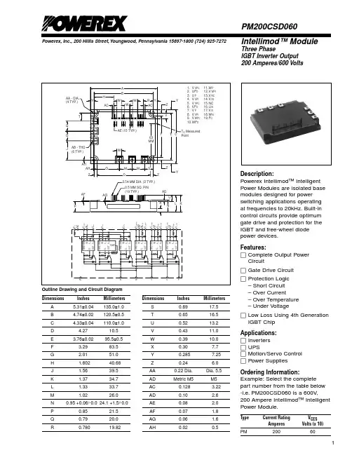
7MBR30SC060资料
- 格式:pdf
- 大小:433.30 KB
- 文档页数:7
7MBR30SC060IGBT Modules
PIM/Built-in converter with thyristorand brake (S series)600V / 30A / PIMFeatures· Low VCE(sat)· Compact Package· P.C. Board Mount Module· Converter Diode Bridge Dynamic Brake Circuit
Applications· Inverter for Motor Drive· AC and DC Servo Drive Amplifier· Uninterruptible Power SupplyMaximum ratings and characteristicsAbsolute maximum ratings (Tc=25°C unless without specified)Item Symbol Condition Rating Unit
Collector-Emitter voltageGate-Emitter voltageCollector currentCollector power disspationCollector-Emitter voltageGate-Emitter voltageCollector currentCollector power disspationRepetitive peak reverse voltage(Diode)Repetitive peak off-state voltageRepetitive peak reverse voltageAverage on-state currentSurge 0n-state current (Non-Repetitive)Junction temperatureRepetitive peak reverse voltageAverage output currentSurge current (Non-Repetitive)I2t (Non-Repetitive)Converter Thyristor Brake Inverter
Junction temperature (except Thyristor)Storage temperatureIsolation between terminal and copper base *2voltage between thermistor and others *3Mounting screw torqueVCESVGESICICP-ICPCVCESVGESICICPPCVRRMVDRMVRRMIT(AV)ITSMTjwVRRMIOIFSMI2tTjTstgVisoContinuous1ms1 device
Continuous1ms1 device
50Hz/60Hz sine waveTj=125°C, 10ms half sine wave
50Hz/60Hz sine waveTj=150°C, 10mshalf sine wave
AC : 1 minute 600 ±20 30 60 30 120 600 ±20 20 40 80 600 800 800 30 275 125 800 30 210 221 +150-40 to +125 AC 2500 AC 2500 1.7 *1VVAAAWVVAAWVVVAA°CVAAA2s°C°CVVN·m*1 Recommendable value : 1.3 to 1.7 N·m (M4)*2 All terminals should be connected together when isolation test will be done.*3 Terminal 8 and 9 should be connected together. Terminal 1 to 7 and 10 to 26 should be connected together and shorted to copper base.元器件交易网www.cecb2b.comElectrical characteristics (Tj=25°C unless otherwise specified)Item Symbol Condition Characteristics Unit Min. Typ. Max.Zero gate voltage collector currentGate-Emitter leakage currentGate-Emitter threshold voltageCollector-Emitter saturation voltageInput capacitanceTurn-on timeTurn-offForward on voltageReverse recovery time of FRDZero gate voltage collector currentGate-Emitter leakage currentCollector-Emitter saturation voltageTurn-on timeTurn-off timeReverse currentoff-state currentReverse current Gate trigger currentGate trigger voltageOn-state voltageForward on voltageReverse currentResistanceB valueThermistor Converter Thyristor Brake InverterICESIGESVGE(th)VCE(sat)CiestontrtofftfVFtrrICESIGESVCE(sat)tontrtofftfIRRMIDMIRRMIGTVGTVTMVFMIRRMRBVCE=600V, VGE=0VVCE=0V, VGE=±20VVCE=20V, IC=30mAVGE=15V, Ic=30A chip terminalVGE=0V, VCE=10V, f=1MHzVCC=300VIC=30AVGE=±15VRG=82ΩIF=30A chip terminalIF=30AVCES=600V, VGE=0VVCE=0V, VGE=±20VIC=20A, VGE=15V chip terminalVCC=300VIC=20AVGE=±15VRG=120ΩVR=600VVDM=800VVRM=800VVD=6V, IT=1AVD=6V, IT=1AITM=30A chip terminalIF=30A chip terminalVR=800VT=25°CT=100°CT=25/50°C 75200 8.5 2.4 1.2 0.6 1.0 0.35 2.6300 75200 2.4 1.2 0.6 1.0 0.35 75 1.0 1.0100 2.5 1.2
1.5 7530005.5 7.8µAnAVVpFµs
VnsµAnAVµs
µAmAmAmAVVVµAΩK
Item Symbol Condition Characteristics Unit Min. Typ. Max.Inverter IGBTInverter FWDBrake IGBTThyristorConverter DiodeWith thermal compound 1.04 2.00 1.56 1.00 °C/W 1.330.05Thermal resistance ( 1 device ) Rth(j-c)
Contact thermal resistance * Rth(c-f)Thermal resistance CharacteristicsIGBT Module7MBR30SC060
* This is the value which is defined mounting on the additional cooling fin with thermal compound1.81.950.450.250.400.051.81.95
1.81.950.450.250.400.05
1.01.11.11.2 5000 465 495 5203305 3375 3450元器件交易网www.cecb2b.comIGBT Module7MBR30SC060Characteristics (Representative)
012345010203040506070
10V12V15VVGE= 20V[ Inverter ]Collector current vs. Collector-Emitter voltageTj= 25°C(typ.)
Collector current : Ic [ A ]
Collector - Emitter voltage : VCE [ V ]012345010203040506070
10V12V15VVGE= 20V[ Inverter ]Collector current vs. Collector-Emitter voltageTj= 125°C(typ.)
Collector - Emitter voltage : VCE [ V ]Collector current : Ic [ A ]
01234010203040506070Tj= 25°CTj= 125°C[ Inverter ]Collector current vs. Collector-Emitter voltageVGE=15V (typ.)
Collector - Emitter voltage : VCE [ V ]Collector current : Ic [ A ]
5101520250246810
Ic= 15AIc= 30AIc= 60A[ Inverter ]Collector-Emitter voltage vs. Gate-Emitter voltageTj= 25°C(typ.)
Collector - Emitter voltage : VCE [ V ]
Gate - Emitter voltage : VGE [ V ]
05101520253035100100010000[ Inverter ]Capacitance vs. Collector-Emitter voltage (typ.)VGE=0V, f= 1MHz, Tj= 25°C
Capacitance : Cies, Coes, Cres [ pF ]
Collector - Emitter voltage : VCE [ V ]CoesCresCies
0501001502000100200300400500[ Inverter ]Dynamic Gate charge (typ.)Vcc=300V, Ic=30A, Tj= 25°C
Gate charge : Qg [ nC ]Collector - Emitter voltage : VCE [ V ]