视频防雷器UT-B101.B201说明书
- 格式:pdf
- 大小:102.54 KB
- 文档页数:3

带外串联间隙型线路避雷器安装使用说明书广州华盛避雷器实业有限公司1用途及特点带外串联间隙型线路避雷器(以下简称避雷器)与线路绝缘子(串)并联安装使用,特别在雷电活动强烈或降低杆(铁)塔接地电阻困难的线段,可有效降低线路雷击跳闸事故率。
避雷器具有放电分散性小、密封性能好、防爆、耐污、体积小、重量轻、运输及安装方便等优点。
2 工作原理因串联间隙的隔离作用,在系统正常运行时,本体基本处于“休息”状态,大部分工频电压由串联间隙承担,由于串联间隙对工频和操作过电压的耐受特性,在工频和操作过电压的作用下,避雷器不动作,只有在雷电过电压的作用下,串联间隙才击穿放电,避雷器动作,限制了雷电过电压,从而确保了被保护的线路绝缘子(串)不发生闪络,并在雷电冲击过后,串联间隙可靠切断工频续流,系统恢复正常运行。
3 正常使用条件a)环境温度不高于+45℃,不低于–40℃;b)太的辐射;c)海拔高度不超过2000m;d)电源频率不小于48Hz,不超过62Hz;e)地震烈度8度及以下地区;f)最大风速不超过35m/s;4 型号及含义5.技术性能避雷器主要技术性能见表1。
6.验收试验用户应对交货的避雷器进行验收试验:⑴按装箱单检查随机文件及附件,应齐全。
⑵测量本体直流1mA参考电压及0.75倍直流1mA参考电压下泄漏电流应符合表1规定(注意:在潮湿及表面污秽时,应采用屏蔽法测量)。
⑶测量串联间隙距离应符合表1规定。
7.贮存避雷器应贮放在环境温度为–40℃~ +45℃、干燥通风、无酸碱及其它有害物质的库房中保存。
8.安装⑴避雷器外形结构及安装尺寸,见图1。
⑵避雷器与被保护的线路绝缘子(串)并联安装使用。
可悬垂安装、水平安装、斜装或其组合方式,依据塔型及实际需要确定,见图2~9。
(a) 悬垂安装悬垂安装于直线塔时,安装支架(杆塔为用抱箍安装于水泥杆上的单支角钢,其悬挂避雷器端用钢索斜拉,铁塔为安装于塔横担上的三角支架,门型杆塔、酒杯型铁塔、猫头型铁塔等单回路塔的中相则可为安装于塔顶的单支角钢)应沿线路方向抬高伸出,35kV、110kV、220kV避雷器与线路绝缘子(串)间的净距离最小值分别为360mm、800mm、1520mm,避雷器与输电导线宜采用并沟线夹或T形线夹连接,安装好后避雷器的最低点应不低于同相输电导线。


VAL-MS230 ST 和F-MS 12 ST 德国菲尼克斯浪涌保护器防雷器防雷器的工作原理:防雷器内部结构其实就是巨功率电压敏感器件,当雷击进入电源进户线路时:防雷器将过高的电压吸收和泄放到大地上,所以地线是很重要的,没有地线就没有防雷效果,只能吸收浪涌效果,当遇到过于强大的雷击时需要空气开关或熔断器(保险丝)来保护,所以空气开关和熔断器的电流要选择合适,不然烧了防雷器还和电网未断开,在空气开关后面再接熔断器是为了更保险,因为空气开关是机械动作的,不会100%可靠。
防雷器的使用必须和空气开关和熔断器配合,理论上讲:空气开关或保险丝电流越小越好,防雷器的并联只数越多效果越好,对雷电的吸收功率越大,但如果选用过大电流的空气开关是不利的,当防雷器达到极限功率时间后,如果空气开关或保险丝未断开是不行的。
使用漏电开关要接在防雷线路之后,漏电开关里面有电子线路,接在防雷线路后面可以保护漏电开关被雷击损坏。
本防雷器属于快速更换结构,当过强雷击被击穿后可以快速更换防雷器芯,不用任何工具,只从防雷器座上拔下和插上,购买时也以多买几个防雷器芯备用,防雷器芯购买请看:德国菲尼克斯PHOENIX CONTACT V AL-MS230 防雷器芯下图是:简单的浪涌保护接线图,本图不能实现防雷保护,只有浪涌保护,空气开关和溶断器大于32A时用两只防雷器并联。
下图是:简单型的防雷和浪涌保护(成本低,效果一般)。
下图是:32A典型防雷浪涌保护接线图(效果最好)。
下图是:63A以下大电流防雷浪涌保护接线图(对线路电流大的也有很好效果)。
下图是: 三相五线防雷浪涌保护接线图,电流大的要用多只并联。
VALVETRAB -MS是一个单通道、导轨安装式的Ⅱ类(C级)电涌保护器。
为了对多路导线进行电涌保护,可以将多个VALVETRAB并联在一起安装,并在接地侧桥接。
VAL MS...VF产品在保护插头中特殊设计了压敏电阻和气体放电管,可以有效限制漏电流。


避雷器阻性泄漏电流检测仪说明书由于输入输出端子、测试柱等均有可能带电压,您在插拔测试线、电源插座时,会产生电火花,小心电击,避免触电危险,注意人身安全!安全要求请阅读下列安全注意事项,以免人身伤害,为了避免可能发生的危险,只可在规定的范围内使用。
只有合格的技术人员才可执行维修。
—防止火灾或人身伤害使用适当的电源线。
只可使用专用并且符合规格的电源线。
正确地连接和断开。
当测试导线与带电端子连接时,请勿随意连接或断开测试导线。
注意所有终端的额定值。
为了防止火灾或电击危险,请注意所有额定值和标记。
在进行连接之前,请阅读使用说明书,以便进一步了解有关额定值的信息。
使用适当的保险丝。
只可使用符合规定类型和额定值的保险丝。
避免接触裸露电路和带电金属。
有电时,请勿触摸裸露的接点和部位。
请勿在潮湿环境下操作。
请勿在易爆环境中操作。
-安全术语警告:警告字句指出可能造成人身伤亡的状况或做法。
目录一、概述 (5)二、仪器面板结构图 (5)三、主要技术指标 (5)四、接线图 (6)五、仪器的操作 (7)六、测量原理和数据分析 (9)七、注意事项 (11)一、概述:氧化锌避雷器测试仪用于氧化锌[MOA] 泄漏电流的测量分析。
主要是用于测量阻性电流,从而分析氧化锌老化和受潮的程度。
现场带电测试符合中华人民共和国电力行业标准《DL474.5—92现场绝缘试验实施导则—避雷器试验》的要术。
也可用于实验室做出厂和验收试验。
二、仪器面板结构图: 返回复位确认开关液晶显示器打印机测量接地IX全电流输入UREF参考电压输入AC220V对比度三、主要技术指标:参考电压输入范围(峰值): 10-400V全泄漏电流测量范围(峰值): 0-10mA阻性电流测量范围(峰值): 0-10mA容性电流测量范围(峰值): 0-10mA角度测量范围: 0°-360°功耗: 4W系统测量准确度: ±(读数⨯5% + 5个字)交流电源: AC 220V ±10%,50Hz ±1% 内附直流电池: DC 12V 2A四、接线图:1. 实验室接线图~220V 测量绕组避雷器电流输入电压输入电流输入避雷器测试仪保护器图2本方法需配可调交流高压电源,电压信号输入接到试验变压器的测量仪表端,氧化锌避雷器一端接高压,另一端经一保护器接地,与仪器的地在联接在一起。
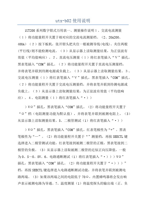
utx-b02使用说明1UT200系列数字钳式万用表一、测量操作说明1、交流电流测量(1)将功能量程开关置于相对应的交流电流测量档。
(2、20A200、400A)(2)按下板机,张开钳头把夹住一根被测导线(电线)。
夹住两根(平行线)则不能检测电流。
(3)从显示器上读取测量结果,为正弦波有效值(平均值响应)。
2、直流电压测量(1)将红表笔插入“V”插孔,黑表笔插入“COM”插孔。
(2)将功能量程开关置于直流电压测量档,并将表笔并联到待测电源或负载上。
(3)从显示器上读取测量结果。
3、交流电压测量(1)将红表笔插入“V”插孔,黑表笔插入“COM”插孔。
(2)将功能量程开关置于交流电压测量档,并将表笔并联到待测电源或负载上。
(3)从显示器上读取测量结果,为正弦波有效值(平均值响应)。
4、电阻测量(1)将红表笔插入“·)))VΩ”插孔,黑表笔插入“COM”插孔。
(2)将功能量程开关置于“Ω”档(电阻测量功能为默认值),并将表笔并联到被测电阻上。
(3)从显示器上读取测量结果。
5、二极管测试(1)将红表笔插入“·)))VΩ”插孔,黑表笔插入“COM”插孔。
红表笔极性为“+”。
黑表笔极性为“—”。
(2)将功能量程开关置于“”测量档,再按SEECTL键选择进入二极管测试功能,红表笔接到被测二极管的正极,黑表笔接到二极管的负极。
(3)从显示器上读取被测二极管的近似正向压降值,一般为0。
5~0。
8V。
6、电路通断测试(1)将红表笔插入“·)))VΩ”插孔,黑表笔插入“COM”插孔。
(2)将功能量程开关置于“·)))”档,再按SEECTL键选择进入电路通断测试功能,并将表笔并联到被测电路两端。
(3)如果该两端之间的电阻低于70Ω,内置蜂鸣器将会发出响声表示被测电路为导通。
7、温度测量(1)将温度探头的输出端(正、负极)分别接入仪表“·)))VΩ”、“COM”输入插孔。
野外训练可移动避雷针,驻训防雷设备,拉练防雷针说明书编辑:郑州万佳防雷有限公司升降避雷针的内置式设计这种内置式升降杆要求当天线升起后,钢丝绳不裸露在外。
这就要求设计时,在杆与杆之间有限的空间内合理安排钢丝绳的缠绕方式。
首先,升降杆的管材截面采用正方形截面。
这是因为(1)杆内壁要安装滑轮,需要大的安装平面,若选用圆管,它的内壁不好安装滑轮;(2)相同壁厚和截面积的管子,方形比圆形的抗弯截面系数大。
第二,天线升降杆的钢丝绳与杆件之间的缠绕形式如前面的结构简图(图1)所示。
主动钢丝绳的安装平面在杆2的中间平面内,从动钢丝绳的安装平面在杆3的中间平面内,且与主动钢丝绳安装平面垂直。
这种形式可以避免两根钢丝绳在同一平面内相互交叉碰闯。
第三,滑轮安装关键在于减小摩擦。
前面的原理受力计算过程忽略了摩擦力,但钢丝绳在滑轮上滚动时产生的摩擦力是实际存在的,而且如果设计考虑不周,摩擦力将很大,直接影响能否提起各级杆以及钢丝绳的粗细。
因此在设计时滑轮内安装滚动轴承。
一、升降避雷针制造步骤与要求◆步骤:①根据图纸要求在土建进行升降避雷针基础施工时,预埋好地脚螺栓等。
②按设计要求的材料所需的长度分上、中、下三节进行下料。
如果升降避雷针的针尖采用钢管制作,先将上节钢管一端锯成锯齿形,用手锤收尖后进行焊缝磨尖、涮锡,然后将另一端与中、下两节找直焊好。
◆要求:①所有升降避雷针的金属部件必须镀锌,操作时注意保护镀锌层。
②采用镀锌钢管管制作针尖,管壁厚度不得小于3mm,针尖刷锡长度不得小于70mm③升降避雷针应垂直安装牢固。
垂直度允许偏差为3/1000。
④焊接要求焊接应采用搭接焊,其搭接长度必须符合下列规定:⑤扁钢为其宽度的2倍(且至少3个棱边焊接)。
⑥圆钢为其直径的6倍。
⑦圆钢与扁钢连接时,其长度为圆钢直径的6倍。
※升降避雷针一般采用圆钢或钢管制成,其直径不应小于下列数值:a.独立升降避雷针一般采用直径为19mm镀锌圆钢。
b.屋面上的升降避雷针采用直径25mm镀锌钢管。
BEFORE USE ....Thank you for choosing M-System. Before use, please check contents of the package you received as outlined below .If you have any problems or questions with the product, please contact M-System’s Sales Office or representatives. ■PACKAGE INCLUDES:Surge protector ....................................................................(1) ■MODEL NO.Check that the model No. described on the specifications matches the operational line voltage and other specifica-tions as shown in ‘PERFORMANCE’ hereafter.■INSTALLATION / INSTRUCTION MANUALThis manual describes necessary points of caution when you use this product, installation, and basic maintenance procedure.LIMITATION APPLICABLE TO MATPHThe MATPH will protect electronics equipment from damage caused by induced lightning by absorbing most of the surge voltages.However, MATPH may not be effective against certain extremely high voltages exceeding its discharge current capacity (20 kA @ 8/20 µsec. waveform) caused by a di-rect or almost direct hit by lightning.The MATPH must be installed according to this installa-tion / instruction manual.PERFORMANCEMax. continuous operating voltage (Uc, Line to line):750 V DC for MATPH-7501000 V DC for MATPH-1000Discharge voltage (Line to earth): 500 V DC Voltage protection level (Up):•MATPH-750Line to line: 2.5 kV (@In)Line to earth: 1.8 kV (@In)•MATPH-1000Line to line: 3.3 kV (@In) Line to earth: 2.1 kV (@In)Maximum discharge current (Imax): 20 kA (8/ 20 μsec.)Nominal discharge current (In): 10 kA (8/ 20 μsec.)Response time:Line to line: ≤ 4 nsec. Line to earth: ≤ 20 nsec.Leakage current: ≤ 1 mAInsulation resistance: ≥ 100 MΩ with 500 V DC (line to alarm output)Dielectric strength: 2000 V AC @ 1 minute (line to alarm output)POINTS OF CAUTION■CONFORMITY WITH EU DIRECTIVES • Altitude up to 2000 meters.• The equipment must be installed such that appropriate clearance and creepage distances are maintained to con-form to CE requirements. Failure to observe these re-quirements may invalidate the CE conformance. ■INSTALLATION •DANGER! D O NOT install the MATPH at the point common to an external lightning protection device such as a lightning rod. The MATPH will be subject to the danger of direct lightning.•DANGER!D O NOT perform an installation and wiring of the MAT-PH during thunder storms.• Indoor use.• Be sure to house the MATPH inside an metal enclosure for safety . Even though the MATPH is capable of with-standing an induced discharge current expected in nor-mal conditions, it is entirely possible to be hit by a certain strong lightning exceeding its designed capacity . It is also subject to a direct hit by a lightning. The MATPH will be destroyed by such high lightning energy .• We recommend to install the MATPH in a position where the monitor LED is clearly visible to facilitate inspection and maintenance.• DO NOT install the MATPH where it is subjected to con-tinuous vibration. Do not apply physical impact to the MATPH.• Environmental temperature must be within -25 to +80°C (-13 to +176°F) and relative humidity within 30 to 90%RH in order to ensure adequate life span and operation. ■HIGH TEMPERATURE •DANGER! T he front parts of the surface may be hot. DO NOT grab the sides of the module. When the MATPH’s discharge element (zinc oxide element) gradually degrades, its increased leakage current causes high temperature at the surface of the MATPH, until the discharge element is finally separated from the power line by the thermal breaker. However, a part of the module may already be too hot to touch safely if the module is near the end of its life. ■DIELECTRIC S TRENGTH TES TING• Conduct the dielectric strength test with all power sup-ply wires removed. The MATPH will start discharging at the described discharge voltage if a test voltage is applied with all power supply wires connected. It will result in an insulation failure. ■AND....• We recommend that you keep spare MATPHs so that you can replace them quickly when necessary .056 222 38 18SEN TRONIC AGFEATURES■CURRENT CAPACITY• The one-port SPD can be used regardless of the load cur-rent.■HIGH PERFORMANCE & RESPONSE TIME• The discharge element (zinc oxide varistor) between the lines does not disturb the power line with follow current normally observed by a spark gap after a discharge. The response time is also very high.■HIGH DISCHARGE CURRENT CAPACITY• The MATPH is designed to withstand 20 kA surges (test waveform 8/20 µsec.). High design standard compared to normally induced surge current level of 1 kA.■THERMAL BREAKER• The power supply voltage is continuously applied to the incorporated discharge element (zinc oxide element). Degraded element is automatically separated from the power lines for safety to prevent overheating caused by leakage current.• The failure is notified visually by the monitor LED and remotely by an alarm contact.■PREVENTING ELECTRIC SHOCK• The MATPH’s terminal section with a terminal cover has IP20 protection level to protect from an electric shock.• The MATPH is designed for use with ring shape solder-less terminals for a wide range of wire sizes from 2 to 14 mm2.■MEASUREMENT OF RESISTANCE TO EARTH• A spark gap is employed as surge suppressor between line and earth. That makes measurement of resistance to earth without removing the SPD even in case switch gears connected. (If the measurement voltage is higher than 500 V DC, remove the SPD.)SCHEMATIC CIRCUITRYѳ: Thermal breakerNote: Terminals A0 & A1 are available for ‘Alarm output’ code ‘A.’INSTALLATION■DIN RAIL MOUNTINGThe MATPH is mounted on a 35-mm-wide DIN rail. Set the MATPH so that its DIN rail adaptor is at the bottom. Posi-tion the upper hook at the rear side of base on the DIN rail and push in the lower.When removing, push down the DIN rail adaptor utilizing a minus screwdriver and pull.CONNECTION PROCEDURE■INSTALLING CIRCUIT BREAKERSThis unit incorporates a thermal breaker which separates the discharge element from the power line upon detecting the in-creased leakage current by the element’s gradual degradation.However, in rare cases, when the unit is hit by an extremely strong lightning which exceeds the unit’s designed induced surge capacity , the discharge element may be burned out and short-circuited at a burst without the thermal breaker being able to separate it safely from the line.Install a circuit breaker at the power source side of the surge protector as a backup protection. The example below shows a photovoltaic system. Molded-case circuit breakers (MCCB), residual current circuit breaker (RCCB) or current limiting fuses (slow-blow type only) can be used.■CONNECTION DIAGRAM■***WIRING■LEADWIRESConductor cross-section area: 5.5 mm2 minimum for both the power and the earth lines. However, a local industrial standard requirement for wiring should take precedence.■SOLDERLESS TERMINALApplicable ring tongue terminal without insulation sleeve is as indicated below. Spade tongue terminal must conform with the ring type size.In order to ensure IP20 protection (IEC 60529) with a sol-derless terminal, cover the terminal with a insulation cap to prevent direct touching by a hand.d : M5 useB ≤ 12.5 mmF ≥ 7.0 mm(F ≥ 8.2 mm for sharing terminals)T ≤ 1.8 mm• Applicable Solderless Terminal Size■TORQUETighten the screw terminals securely. Maximum allowabletorque is of 2.5 N·m.■WIRE LENGTHK eep the wire length to the minimum for both the powersource side and the earth side. The wire length between thebranch point and the earth should ideally be less than 0.5meters. Extra long wires should not be bundled in coils, butbe cut to the minimum required length.EARTHING■COMMON EARTHING WITH CROSS-OVER WIREBasically a common earthing with cross-wiring between theMATPH and the protected device is recommended for ad-equate protection. Earthing resistance should be less than100 ohms. If the protected device has no earth terminal,earth only the MATPH.The earthing point should be close to the MATPH side asshown below.ALARM OUTPUTOptional breack-contact relay output is available to alertwhen the thermal breaker has separated the discharge ele-ment from the power supply circuit.If the alarm output should be transmitted remotely via out-door cables, a surge protector for signal line is required.Choose a circuit breaker with an alarm output. Configure alogical addition sequence so that the alarm trips when bothor either of the MATPH or the breaker alarm trips.■RELAY SPECIFICATIONSAlarm output: T he breack-contact relay trips when the ther-mal breaker operates.Rated load: 250V AC @50mA (resistive load)24V DC @50mA (resistive load)■CONNECTIONTerminal: Tension clampApplicable wire size: 0.13 to 1.5 mm2Stripped length: 8 mmCHECKING■WIRING• Make sure that wiring is done as instructed in the con-nection diagram.• Make sure that the earth terminal (G) is connected to themetallic housing of protected equipment.• Make sure that the earth terminal (G) is earthed to earth.MAINTENANCEEven lightning in remote locations could induce surges without our knowledge. Regular checking of the surge pro-tector is important to find degradations in early stage, be-fore and after the storm seasons, and whenever you experi-ence a strong lightning storm.DO NOT attempt checking or replacing the surge protector during a thunder storm for safety.Checking procedure is as explained below:■CHECK EXTERIORIf discoloration or deformation is observed, replace with a new one immediately.■CHECK MONITOR LEDGreen LED turns on during normal operation, indicating the surge protector is functioning properly. Turning off means that the protector is in failure. Replace with a new one immediately.When the voltage between L+ and L- is low, the monitor LED may be dark. In that case, check the LED with a insu-lation tester (100 V DC to operational voltage). When the polarity is opposite, change it.EXTERNAL DIMENSIONS & TERMINAL ASSIGNMENT Unit: mm (inch)* Only for 'Alarm output' code 'A.'。
防雷安装手册企业商用产品版权所有©2021深圳市和为顺网络技术有限公司。
保留一切权利。
约定由于产品版本升级或其它原因,本文档内容会不定期更新。
文中所有信息仅作为使用指导,不构成任何形式的担保。
本手册制定过程中,参考了以下标准:- GB 50343-2012《建筑物电子信息系统防雷技术规范》- GB 50057-2010《建筑物防雷设计规范》- YD/T 5098-2001《通信局(站)雷电过电压保护工程设计规范》- GB 4943-2011《信息技术设备的安全》- GB/T 18802.21-2016《电信和信号网络的电涌保护器(SPD)性能要求和试验方法》本手册适用于IP-COM企业商用产品的防雷安装,以交换机为例进行说明。
参考文献目录第1章 防雷术语及基本常识 (1)1.1 术语 (1)1.2 雷电常识 (2)1.2.1 雷击的危害 (2)1.2.2 雷击的分类 (2)1.2.3 雷击入侵网络设备的途径 (2)1.2.4 雷击的防护 (3)第2章 设备防雷安装 (4)2.1 接地 (4)2.1.1 接地的一般要求 (4)2.1.2 接地方法 (5)2.2 合理布线 (7)2.2.1 布线的一般要求 (7)2.2.2 线缆安装方法 (7)2.3 等电位连接 (9)2.3.1 等电位连接的一般要求 (9)2.3.2 等电位连接方法 (9)第3章 使用防雷器 (10)3.1 使用电源防雷器 (10)3.2 使用网口防雷器 (10)第1章 防雷术语及基本常识1.1 术语术语雷击雷云间,或雷云对大地及地面物体的迅速放电现象直击雷雷云与大地上的某一点发生的迅猛的放电现象雷电过电压接地感应雷解释将导体连接到“地”,使之具有近似大地(或代替大地)的电位接闪器包括避雷针、避雷带(线)、避雷网,以及用作接闪的金属屋面或金属构件接地体为达到与地连接的目的,一根或一组与土壤(大地)密切接触并提供与土壤(大地)之间电气连接的导体雷云放电后产生的感应电压或感应电磁场对附近物体的破坏现象因特定的雷电放电,在系统中一定位置上出现的瞬态过电压接地引下线从引下线断接卡或换线处至接地体的连接导体;或从接地端子、等电位连接带至接地体的连接导体BGND 直流地,机箱直流供电电源的接地,一般是将-48V DC的正极在电源柜处进行接地,也可采用 RTN表示接地网为实现良好接地,由接地体演变而来的大面积金属栅格接地端子设备的保护接地端(PE)PE 保护地,机箱及机箱内各种设备金属外壳的保护接地等电位连接直接用连接导体或通过浪涌保护器将分离的金属部件、外来导电物、电力线路、通信线路及其他电缆连接起来以减小雷电流在它们之间产生电位差的措施GND 工作地,机箱中各种设备功能电路的接地,是单板及母板上的数字地和模拟地的统称共用接地系统将防雷系统的接地装置、建筑物金属构件、低压配电保护线(PE)、等电位连接端子板或连接带、设备保护地、屏蔽体接地、防静电接地、功能性接地等连接在一起构成共用的接地系统雷电引下线用于将雷电流从接闪器传导至接地装置的导体1.2.1 雷击的危害1.2 雷电常识雷击是严重自然灾害之一。
控制信号保护器
1. 概述
本雷击浪涌保护器参照国家标准IEC61643-21:2000 / GB/T18802.21设计。
随着国民经济的发展,互联网时代的发展日益月新,互联网技术发展进步神速。
然而,却不能无视发展中存在这样或者那样的问题,安全问题是放在第一位的。
日常生活中,雷电对于电子设备的损坏是最严重的,静电产生的威胁也无处不在,为了广大用户有一个更安全的使用环境,提高设备可靠性的要求的呼声也越来越强烈。
2. 功能特点
适用于控制信号、视频信号为一体的监控系统信号过电压防护,使其免受感应过电压、操作过电压和静电放电等所造成的损坏;多级保护、通流容量大、限制电压低、响应时间快、插入损耗小等优点。
3. 使用环境
温度:-40℃~85℃;
相对湿度:5%~95%;
大气压:70kPa~106 kPa.
4. 工作原理
雷击浪涌保护器串接于被保护设备的前端,当传输线遭到感应雷及其它瞬时过电压冲击时,冲击电流通过浪涌保护器的保护支路将其泄放到大地,并将输出电压钳位在设备允许的电压范围内,从而确保了运行设备的安全。
5. 技术指标
型号UT-B101 UT-B201 额定工作电压Un 5V 5V
最大直流工作电压Uc 6V 6V
最大交流工作电压Uc 4.2V 4.2V
额定工作电流IL 0.12A 0.12A
标称放电电流(8/20 us)In 3KA 5KA
最大放电电流In 5KA 10KA
限制电压Upl ≤11V ≤13V
线的串联阻抗特性Ro 10 Ohm 10 Ohm
线与地之间的电容值Cpe ≤10pF ≤10pF
响应时间ta <1 ns <1 ns
工作温度范围-40℃~85℃-40℃~85℃
测试标准IEC61000-4-5 IEC61000-4-5
测试等级X X
绝缘电阻>1MΩ >1MΩ
插入损耗(dB)≤0.5 dB ≤0.5dB
外壳防护等级IP30 IP30
外形尺寸25*25*88 25*25*88
外壳材料屏蔽金属铝屏蔽金属铝
接线形式BNC(K/J) BNC(K/J)
防静电等级4级4级
传输速率(BPS)200M 200M
、使用和维护
安装、
6 安装
6.1安装说明
6.1.1将保护器接入系统前,先检查地网接地电阻,应符合规范要求。
6.1.2将保护器接入被保护设备前端,必须连接可靠。
6.1.3将保护器的接地线尽可能短地连接到保护接地母线上。
6.2注意事项
6.2.1保护器上有输入(IN)、输出(OUT)标志,输出端与被保护设备连接,切勿接反。
否则会造成保护器的损坏,设备也无法得到保护。
6.2.2若由于插头座连接不良等因素引起损耗增大,应重新连接或更换保护器。
6.2.3用户不可随意拆卸保护器各部位的紧固件,以免造成损坏,影响正常工作。
6.3保护器的检查
6.3.1用三用表“Ω×1”档测量保护器输入芯线与输出芯线之间的电阻约为10 Ω;若开路,则不正常,应更换保护器。