Juniper netscreen 防火墙三种部署模式及基本配置
- 格式:docx
- 大小:21.13 KB
- 文档页数:6
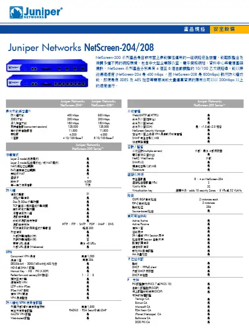
系統管理WebUI(HTTP 與HTTPS)命令列介面(控制台)命令列介面(telnet)命令列介面(SSH)NetScreen-Security Manager在任何介面上透過VPN 通道執行所有管理SNMP 完全客製化MIBMicrosoft CA RSA Keon CAiPlanet (Netscape) CA Baltimore CA DOD PKI CA內建(內部)資料庫使用者限制第三方使用者認證XAUTH VPN 認證Web-based 認證Juniper Networks NetScreen-204/208NetScreen-200 系列產品是目前市面上最能彈性運用的一組網路安全裝置,能輕鬆整合及保護多種不同的網路環境,包含中大型企業辦公室、電子商務網站、資料中心與電信基礎建設。
NetScreen 系列產品分別具有 4 個至 8 個自動調整的 10/100 乙太網路埠,能以接近連線速度 (NetScreen-204 是 400 Mbps ,而 NetScreen-208 是 800Mbps) 執行防火牆功能。
即便是像 3DES 及 AES 加密等需要消耗大量運算資源的應用也可以以 200Mbps 以上的速度進行。
最大效能與容量(2)防火牆效能3DES 效能深入檢查效能同時會話數(concurrent sessions)每秒的新會話數目策略數介面數400 Mbps 200 Mbps 180 Mbps 128,00011,5004,0004 10/100 Base-T550 Mbps 200 Mbps 180 Mbps 128,00011,5004,0008 10/100 Base-T高達1,500RADIUS 、RSA SecurID 與LDAP是是是是是是,v1.5與v2.0 相容是是是是是是是是是管理本地管理資枓庫外部管理資料庫限制性管理網路根管理、管理和唯讀用戶權限軟體升級組態自動恢復路徑管理保障頻寬最大頻寬優先頻寬利用DiffServ stamp外部FlashCompactFlash TM 事件日誌和預警系統配置腳本NetScreen ScreenOS 軟體尺寸與電源尺寸(H/W/L)重量機架掛載電源供應(AC)電源供應(DC)認證安全認證UL 、CUL 、CSA 、CB 、NEBS Level 3 (NetScreen-208 含DC 電源供應)EMC 認證FCC A 級、BSMI 、CE A 級、C-Tick 、VCCI A 級操作環境作業溫度:23°to 122° F 、-5°to 50° C 非作業溫度:-4°to 158° F 、-20°to 70° C 溼度:10 to 90%非冷凝MTBF (Bellcore 機型)NetScreen-204:6.8 年、NetScreen-208:6.5 年安全性認證 (僅限高階機型)Common Criteria :EAL4+FIPS 140-2:Level 2ICSA 防火牆與VPN訂購資訊NetScreen-208美式電源線NS-208-001NetScreen-208英式電源線NS-208-003NetScreen-208歐式電源線NS-208-005NetScreen-208日式電源線NS-208-007Juniper NetScreen-208 w/DC 電源供應NetScreen-208直流電源NS-208-001-DC Juniper NetScreen-204 w/AC 電源供應NetScreen-204美式電源線NS-204-001NetScreen-204英式電源線NS-204-003NetScreen-204歐式電源線NS-204-005NetScreen-204日式電源線NS-204-007Juniper NetScreen-204 w/dC 電源供應NetScreen-204直流電源NS-204-001-DCJuniper NetScreen-200 系列虛擬化技術NetScreen-200 Virtualization KeyNS-200-VIRTVirtualization Key 增加 32 VLANs 、5 個額外的虛擬路由,與 10 個額外的安全區。

Juniper NetScreen防火墙新人指南(WEB、CLI)来源:作者:netscreen时间:01-03 06:02:55浏览:737【大中小】NetScreen防火墙支持多种管理方式:WEB管理,CLI (Telnet) 管理等,由于一般调试工作中,我们最常用的也就是前面两种。
(ScreenOS 4.0)首先,使用CONSOLE口进行配置1.把配送的线的一端插在防火墙的CONSOLE口,线的另一端插在转换插头后插在PC的串行口上。
2.打开WINDOWS的附件-》通讯-》超级终端,选择插有CONSOLE线的串口连接。
(设置串口属性:9600-8-无-硬件)3.出现提示符号后输入帐号密码进入设置命令行界面。
(默认帐号:Netscreen;密码Netscreen)4.进入Netscreen命令行管理界面 }B4BWeb管理连接设置1. 设置接口IP;若所有接口均未配置IP(Netscreen设备初始化设置),需设置一个端口IP,用于连接web管理界面,这里设置trust端口;在命令行模式下输入: ns5XT->set int trust ip *命令说明: A.B.C.D为IP地址,通常设置为一个内网地址,E 为IP地址的掩码位,通常设为24。
此时通过get interface命令可以看到端口状态的信息(类似CISCO SHOW 接口命令)2.启动接口的web管理功能; ns5XT->set int trust manage web3.连通PC和防火墙间的网络,通过浏览器的web界面进行具体功能设置 DW,建立对于NS-5,NS-10,NS-100防火墙,PC与trust口,DMZ口采用直通电缆连接,PC与untrust 口的连接采用交叉线。
对于NS-25,NS-200及以上产品,PC与防火墙所有端口的连接都采用直通电缆。
注意:将PC网卡的IP地址设置成与防火墙相应端口的管理IP同一个网段内;打开IE浏览器,键入防火墙的管理IP,打开登陆画面;防火墙基本设置:1.设置访问超时时间:Web: 在Web中的Configuration>Admin>Management中的Enabel Web Management Idle Timeout 中填入访问超时的分钟数,并在前面打勾。
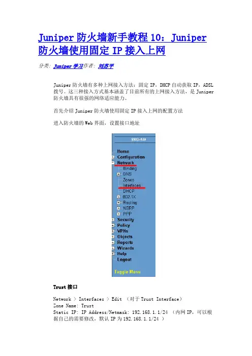
Juniper防火墙新手教程10:Juniper 防火墙使用固定IP接入上网分类: Juniper学习作者: 刘苏平Juniper防火墙有多种上网接入方法:固定IP,DHCP自动获取IP,ADSL拨号。
这三种接入方式基本涵盖了目前所有的上网接入方法,是Juniper防火墙具有很强的网络适应能力。
首先介绍Juniper防火墙使用固定IP接入上网的配置方法进入防火墙的Web界面,设置接口地址Trust接口Network > Interfaces > Edit (对于Trust Interface)Zone Name: TrustStatic IP: IP Address/Netmask: 192.168.1.1/24 (内网IP,可以根据自己的需要修改,默认IP为192.168.1.1/24 )Interface Mode: NAT默认的管理地址(Manage IP)与接口地址相同,但也可以更改,但管理地址必须与接口地址在同一网段中。
Untrust接口Network > Interfaces > Edit (对于Untrust Interface)Zone Name: UntrustStatic IP: IP Address/Netmask: 外网IP (输入接入商给的外网IP 及掩码地址)Interface Mode: Route设置路由只有对于使用固定IP地址线路接入方式,才需要设置默认路由。
其他两种接入方式,防火墙会自动添加默认路由的。
Network > Routing > Destination选择trust-vr,NewIP Address/Netmask: 0.0.0.0/0.0.0.0选择Gageway,Interface选择Untrust接口,Gateway IP Address填写接入商提供的网关IP。
设置策略部分低端的防火墙中默认有一条From Trust To Untrust,原地址为ANY,目标地址为ANY,服务为ANY的允许策略。

Juniper 网络安全防火墙设备快速安装手册目录1、前言 (4)1.1 、J UNIPER防火墙配置概述 (4)1.2 、J UNIPER防火墙管理配置的基本信息 (4)1.3 、J UNIPER防火墙的常用功能 (5)2、JUNIPER防火墙三种部署模式及基本配置 (6)2.1 、NAT模式 (6)2.2 、R OUTE-路由模式 (7)2.3 、透明模式 (8)2.4 、基于向导方式的NAT/R OUTE模式下的基本配置 (8)2.5 、基于非向导方式的NAT/R OUTE模式下的基本配置 (17)2.5.1 、NS-5GT NAT/Route模式下的基本配置 (18)2.5.2 、NS-25-208 NAT/Route模式下的基本配置 (19)2.6 、基于非向导方式的透明模式下的基本配置 (20)3、JUNIPER防火墙几种常用功能的配置 (21)3.1 、MIP的配置 (21)3.1.1 、使用Web浏览器方式配置MIP (22)3.1.2 、使用命令行方式配置MIP (24)3.2 、VIP的配置 (24)3.2.1 、使用Web浏览器方式配置VIP (25)3.2.2 、使用命令行方式配置VIP (26)3.3 、DIP的配置 (27)3.3.1 、使用Web浏览器方式配置DIP (27)3.3.2 、使用命令行方式配置DIP (29)4、JUNIPER防火墙IPSEC VPN的配置 (29)4.1 、站点间IPS EC VPN配置:STAIC IP-TO-STAIC IP (29)4.1.1 、使用Web浏览器方式配置 (30)4.1.2 、使用命令行方式配置 (34)4.2 、站点间IPS EC VPN配置:STAIC IP-TO-DYNAMIC IP (36)4.2.1 、使用Web浏览器方式配置 (37)4.2.1、使用命令行方式配置 (40)5、JUNIPER中低端防火墙的UTM功能配置 (42)5.1 、防病毒功能的设置 (43)5.1.1 、Scan Manager的设置 (43)5.1.2 、Profile的设置 (44)5.1.3 、防病毒profile在安全策略中的引用 (46)5.2 、防垃圾邮件功能的设置 (48)5.2.1 、Action 设置 (49)5.2.2 、White List与Black List的设置 (49)5.2.3 、防垃圾邮件功能的引用 (51)5.3 、WEB/URL过滤功能的设置 (51)5.3.1 、转发URL过滤请求到外置URL过滤服务器 (51)5.3.2 、使用内置的URL过滤引擎进行URL过滤 (53)5.3.3 、手动添加过滤项 (54)5.4 、深层检测功能的设置 (58)5.4.1 、设置DI攻击特征库自动更新 (58)5.4.2 、深层检测(DI)的引用 (59)6、JUNIPER防火墙的HA(高可用性)配置 (61)6.1 、使用W EB浏览器方式配置 (62)6.2 、使用命令行方式配置 (64)7、JUNIPER防火墙一些实用工具 (65)7.1 、防火墙配置文件的导出和导入 (65)7.1.1 、配置文件的导出 (66)7.1.2 、配置文件的导入 (66)7.2 、防火墙软件(S CREEN OS)更新 (67)7.3 、防火墙恢复密码及出厂配置的方法 (68)8、JUNIPER防火墙的一些概念 (68)1、前言我们制作本安装手册的目的是使初次接触Juniper 网络安全防火墙设备(在本安装手册中简称为“Junip er防火墙”)的工程技术人员,可以通过此安装手册完成对Juniper防火墙基本功能的实现和应用。

juniper netscreen FW的常用配置1.Juniper防火墙管理配置的基本信息Juniper防火墙常用管理方式:①通过Web浏览器方式管理。
推荐使用IE浏览器进行登录管理,需要知道防火墙对应端口的管理IP地址;②命令行方式。
支持通过Console端口超级终端连接和Telnet防火墙管理IP地址连接两种命令行登录管理模式。
Juniper防火墙缺省管理端口和IP地址:① Juniper防火墙出厂时可通过缺省设置的IP地址使用Telnet或者Web方式管理。
缺省IP地址为:192.168.1.1/255.255.255.0;②缺省IP地址通常设置在防火墙的Trust端口上(NS-5GT)、最小端口编号的物理端口上(NS-25/50/204/208/SSG系列)、或者专用的管理端口上(ISG-1000/2000,NS-5200/5400)。
Juniper防火墙缺省登录管理账号:①用户名:netscreen;②密码:netscreen。
2. 配置ns达到内网能访问internet的要求,我们经常使用的方式是nat/route的方式,主要的配置过程为:NS-5GT NAT/Route模式下的基本配置注:NS-5GT设备的物理接口名称叫做trust和untrust;缺省Zone包括:trust和untrust,请注意和接口区分开。
① Unset interface trust ip (清除防火墙内网端口的IP地址);② Set interface trust zone trust(将内网端口trust分配到trust zone);③ Set interface trust ip 192.168.1.1/24(设置内网端口trust的IP地址,必须先定义zone,之后再定义IP地址);④ Set interface untrust zone untrust(将外网口untrust分配到untrust zone);⑤ Set interface untrust ip 10.10.10.1/24(设置外网口untrust的IP地址);⑥ Set route 0.0.0.0/0 interface untrust gateway 10.10.10.251(设置防火墙对外的缺省路由网关地址);⑦ Set policy from trust to untrust any any any permit log(定义一条由内网到外网的访问策略。


Juniper NetScreen配置手册透明模式将防火墙配置为透明模式1.创建2层Zoneset zone name <name> L2 <vlan_tag>例:set zone name L2-Demo L2 12.把接口划到安全区set interface <int-name> zone <zone-name>例:set interface e3 zone L2-Demo3.a.配置IP地址set zone name <name> L2 <vlan_tag>例:ns208-> set zone name L2-Demo L2 1set interface <int-name> zone <zone-name>例:set interface e3 zone L2-Demob.选择广播选项set vlan1 broadcast <flood | arp>c.配置Vlan的管理选项set interface vlan1 manage例:set int vlan1 manageset interface vlan1 manage [<service>]例:set int vlan1 manage webset int vlan1 manage sslset int vlan1 manage nsmgmtd.为每个Zone配置管理选项set zone <name> manage [<service>]例:set zone v1-dmz manage web透明模式下的检查工具Get interfaceGet ARPGet mac-learnGet session三层操作模式将防火墙配置为三层操作模式1.创建Zoneset zone name <name>例:set zone name Private2.把接口分配到Zoneset interface <int-name> zone <zone-name>例:set interface e8 zone untrust3.给接口指定IP地址set interface <name> ip <X.X.X.X>/<mask>例:set interface e8 ip 1.1.8.1/244.配置静态路由set route <network>/<mask> interface <out_int> gateway <nhr>例:set route 10.1.10.0/24 interface e1 gateway 10.1.1.254验证路由get route ip <address>例:ns208-> get route ip 10.1.10.5Destination Routes for 10.1.10.5---------------------trust-vr : => 10.1.10.0/24 (id=6) via 10.1.1.254 (vr: trust-vr)Interface ethernet1 , metric 1显示VR例:ns208-> get vrouterID Name Vsys Owner Export Routes OSPF BGP RIP1 untrust-vr Root shared n/a 0/max* 2 trust-vr Root shared no 8/maxtotal 2 vrouters shown and 0 of them defined by user* indicates default vrouter for the current vsys配置两个VR1.把Zone划到VR中set zone <name> vrouter <name>例:set zone Untrust vrouter untrust-vr2.给zone指定接口3.给接口分配IP地址4.配置VR间路由set vrouter <name> route <network>/<mask> vrouter <name>例:set vrouter untrust-vr route 10.1.10.0/24 vrouter trust-vr配置接口模式set interface <name> [route | nat]例:set interface e1 nat策略的配置及高级选项创建策略1.创建地址表2.创建服务查看预定义的服务get service pre-defined创建自定义服务set service name <protocol> <(parameters vary)>3.创建策略set policy from <zone> to <zone> <source_addr> <dest_addr> <service> [permit | deny] 例:set policy from private to public 10.1.10.5/32 any http permit4.策略排序set policy move <id> [before | after] <id>例:set policy move id 5 before 4配置选项1.创建并查看地址组set group address <zone> <name> add <addr-name>例:set group address Private Admins add Admin1set group address Private Admins add Admin2get group address <zone>例:get group address PrivateGroup Name Count CommentAdmins 2get group address <zone> <group-name>例:get group address Private AdminsGroup Name: AllowedServices Comment:Group Items: 5Members: "FTP" "HTTP" "PING" "TELNET" "TFTP"2.创建并查看服务组set group service <name> add <service>get group service例:get group serviceGroup Name Count CommentAllowedServices 5get group service <group-name>例:get group service AllowedServicesGroup Name: AllowedServices Comment:Group Items: 5Members: "FTP" "HTTP" "PING" "TELNET" "TFTP"3.创建多单元策略高级选项1.配置流量日志并验证访问日志set policy (from zone to zone sa da service action) log–或者–set policy log例:ns5gt-> set policy id 1ns5gt(policy:1)-> set policy logget log traffic2.配置流量统计并验证流量统计set policy (from zone to zone sa da service action) count–或者–set policy countset policy count alarm <bytes/sec> <kbytes/min>例:ns5gt-> set policy id 1ns5gt(policy:1)-> set policy countget counters policy <id> <time parameters>3.创建计划并应用计划到策略中set scheduler <name> recurrent <day> start <time> stop <time> [start <time> stop <time>] 例:set scheduler NoICQ recurrent mon start 7:00 stop 12:00 start 13:00 stop 18:00 set scheduler NoICQ recurrent tues start 7:00 stop 12:00 13:00 stop 18:00(etc.)set scheduler <name> once start <mm/dd/yyyy> stop <mm/dd/yyyy>例:set scheduler Y2K once start 01/01/2000 stop 01/02/2000set policy (from zone to zone sa da service action) schedule <name>认证的配置1.创建用户数据库set user <name> password <password>2.配置认证策略set policy (from zone to zone sa da service action) authset policy (from zone to zone sa da service action) webauth3.配置WebAuth地址(只用于WebAuth)set interface <name> webauthset interface <name> webauth-ip <ip>4.确认认证配置ns5gt-> get user allTotal users: 1Id User name Enable Type ID-type Identity Belongs to groups----- --------------- ------ ------- ------- ---------- -----------------1 JoeUser Yes authns5gt-> get auth tableTotal users in table: 1Successful: 1, Failed: 0Pending : 0, Others: 0Col T: Used: D = Default settings, W = WebAuth, A = Auth server in policyid src user group age status server T srczone dstzone1 192.168.1.33 JoeUser 5 Success Local W N/A N/A基于策略的NAT配置NA T-src配置过程1.创建DIP端口转换set interface <name> dip <4-255> <start_address> [<end_address>]例:set interface e8 dip 5 1.1.10.2 1.1.10.254禁止端口转换set interface <name> dip <4-255> <start_address> [<end_address>] fix-port例:set interface e8 dip 5 1.1.10.2 1.1.10.254 fix-port地址变换set interface <name> dip <4-255> shift-from <priv-addr> <start_address> [<end_address>] 例:set interface e8 dip 5 shift-from 10.1.1.5 1.1.10.2 1.1.10.402.创建策略set policy from <zone> to <zone> <SA> <DA> <service> nat src [dip id <num>] permit不带DIP:ns208> set policy from Private to External any any any nat src permit带DIP:ns208> set policy from Private to External any any any nat src dip 5 permitNA T-dst配置过程1.配置地址表条目set address <zone> <name> <address>/<mask>例:set address Private MyPCPublic 1.1.10.20/322.A.配置可达性– Secondary 地址set interface <name> ip <address>/<mask> secondary例:set interface e1 ip 1.1.10.1/24 secondaryB.配置可达性–静态路由set route <network>/<mask> int <outbound int>例:set route 1.1.10.20/32 int e13.配置策略一对一set policy from <zone> to <zone> <SA> <DA> <service> nat dst ip <addr> permit例:set policy from External to Private any MyPCPublic http nat dst ip 10.1.20.5 permit地址变换set policy from <zone> to <zone> <SA> <DA> <service> nat dst ip <range start> <range end> permit例:set policy from External to Private any PublicRange http nat dst ip 10.1.40.1 10.1.40.254 permit端口转换set policy from <zone> to <zone> <SA> <DA> <service> nat dst ip <addr> port <port num> permit例:set policy from External to Private any MyPCPublic http nat dst ip 10.1.20.5 port 8080 permitMIP配置过程1.定义MIPset int <name> mip <publicIP> host <privateIP>例:set int e8 mip 1.1.8.15 host 10.1.10.52.配置MIP策略set policy from <zone> to <zone> <SA> MIP(<addr>) <service> permitVIP配置过程1.定义VIPset int <name> vip <publicIP> <port> <service> <privateIP>例:set int e8 vip 1.1.8.100 23 telnet 10.0.0.5set int e8 vip 1.1.8.100 21 ftp 10.1.20.5set int e8 vip 1.1.8.100 80 http 10.1.30.52.定义策略set policy from <zone> to <zone> <SA> VIP(<addr>) <service> permit例;set policy from untrust to private any VIP::4 any permitVPN配置基于策略的VPN1.设置最大分片长度set flow tcp-mss2.配置IKE网关set ike gateway <name> address <gate_IP> preshare <key> sec-level [standard | basic | compatible]3.创建IKE VPNset vpn <name> gateway <Phase1_gate_name> sec-level [standard | basic | compatible]4.创建地址对象5.配置VPN策略例:set ike gateway toCorporate address 4.4.4.250 preshare XXX sec-level standard set vpn CorporateVPN gateway toCorporate sec-level standardset address Trust HomeNet 10.1.0.0/32set address Untrust CorpNet 10.50.0.0/16set policy from Trust to Untrust HomeNet CorpNet any tunnel vpn CorporateVPNset policy from Untrust to Trust CorpNet HomeNet any tunnel vpn CorporateVPN验证VPN通道1.产生数据–ping, telnet, http, ftp, etc…例:ns208-> ping 10.50.0.5 from trustType escape sequence to abortSending 5, 100-byte ICMP Echos to 10.50.0.5, timeout is 2 seconds from ethernet8!!!!!Success Rate is 100 percent (5/5), round-trip time min/avg/max=40/40/41 ms2.检查第一阶段网关状态例:ns208-> get ike cookieActive: 1, Dead: 0, Total 1522f/3, 1.1.1.250->4.4.4.250: PRESHR/grp2/3DES/SHA, xchg(2) usr(d-1/u-1)resent-tmr 0 lifetime 28800 lt-recv 28800 nxt_rekey 25813 cert-expire 0initiator 1, in-out 1, err cnt 0, send dir 0, cond 0nat-traversal map not availableike heartbeat : disabledike heartbeat last rcv time: 0ike heartbeat last snd time: 0XAUTH status: 03.检查第二阶段SA的活动状态例:ns208-> get sa activeTotal active sa: 1HEX ID Gateway Port Algorithm SPI Life:sec kb Sta PID vsys00000001< 4.4.4.250 500 esp:3des/sha1 8150f85b 3563 unlim A/- 3 000000001> 4.4.4.250 500 esp:3des/sha1 cb0bed95 3563 unlim A/- 2 0排错1.第一阶段:不可识别的网关发起端例:ns208-> get eventDate Time Module Level Type Description2003-04-30 01:53:17 system info 00536 IKE<1.1.1.250> >> <4.4.4.250> Phase 1:Initiated negotiations in main mode.响应端例:ns208-> get eventDate Time Module Level Type Description2003-04-30 01:53:24 system info 00536 IKE<1.1.1.250> Phase 1: Rejected aninitial Phase 1 packet from anunrecognized peer gateway.提议不匹配发起端例:ns208-> get eventDate Time Module Level Type Description2003-04-30 01:58:00 system info 00536 IKE<1.1.1.250> Phase 1: Retransmissionlimit has been reached.2003-04-30 01:56:57 system info 00536 IKE<1.1.1.250> >> <4.4.4.250> Phase 1:Initiated negotiations in main mode.响应端例:ns208-> get eventDate Time Module Level Type Description2003-04-30 01:57:10 system info 00536 IKE<1.1.1.250> Phase 1: Rejectedproposals from peer. Negotiationsfailed.2003-04-30 01:57:10 system info 00536 IKE<1.1.1.250> Phase 1: Responderstarts MAIN mode negotiations.2.第二阶段:提议不匹配发起端例:ns208-> get eventTotal event entries = 72Date Time Module Level Type Description2003-04-30 01:53:09 system info 00536 IKE<4.4.4.250> Received notify messagefor DOI <1> <14> <NO_PROPOSAL_CHOSEN>.响应端例:ns208-> get eventDate Time Module Level Type Description2003-04-30 01:51:01 system info 00536 IKE<1.1.1.250> Phase 2 msg-id<9e9d9b91>: Negotiations have failed.2003-04-30 01:51:01 system info 00536 IKE<1.1.1.250> Phase 2: Rejectedproposals from peer. Negotiationsfailed.ProxyID 不匹配发起端例:ns208-> get eventDate Time Module Level Type Description2003-04-30 02:05:59 system info 00536 IKE<4.4.4.250> Phase 2: Initiatednegotiation.2003-04-30 02:05:59 system info 00536 IKE<4.4.4.250> Phase 1: Completed Mainmode negotiations with a<28800>-second lifetime.远端的ProxyID例:ns208-> get eventDate Time Module Level Type Description2003-04-30 02:05:10 system info 00536 IKE<1.1.1.250> Phase 2: No policyexists for the proxy ID received:local ID (<10.0.0.0>/<255.255.255.0>,<0>,<0>) remote ID (<20.0.0.0>/<255.255.255.0>,<0>,<0>)本地的ProxyID例:ns5gt-> get policy id 3name:"none" (id 3), zone Untrust -> Trust,action Tunnel, status "enabled", pairpolicy 2src "CorpNet", dst "HomeNet", serv "ANY"<output omitted>proxy id:local 10.1.0.0/255.255.255.255, remote 10.50.0.0/255.255.0.0, proto 0, port 0No AuthenticationNo User, User Group or Group expression set解决不匹配的问题例:ns5gt-> unset policy id 2ns5gt-> unset policy id 3ns5gt-> unset address untrust CorpNetns5gt-> unset address trust HomeNetns5gt-> set address untrust CorpNet 10.0.0.0/24ns5gt-> set address trust HomeNet 20.0.0.0/24ns5gt-> set policy from trust to untrust HomeNet CorpNet any tunnel MyVPN policy id = 2ns5gt-> set policy from untrust to trust CorpNet HomeNet any tunnel MyVPN policy id = 3ns5gt-> get policy id 3name:"none" (id 3), zone Untrust -> Trust,action Tunnel, status "enabled", pairpolicy 2src "CorpNet", dst "HomeNet", serv "ANY"<output omitted>proxy id:local 10.0.0.0/255.255.255.0, remote 20.0.0.0/255.255.0.0, proto 0, port 0基于路由的VPNset vpn <name> bind interface <int_name>ns5xt> set interface tunnel.1 zone trustns5xt> set interface tunnel.1 ip unnumberedns5xt> set ike gateway toCorporate address 4.4.4.250 preshare XXX sec-level standard ns5xt> set vpn CorporateVPN gateway toCorporate sec-level standardns5xt> set vpn CorporateVPN bind interface tunnel.1ns5xt> set route 20.0.0.0/8 int tunnel.1验证配置1.产生数据-ping, telnet, http, ftp, etc…例:ns208-> ping 10.0.0.5 from e8Type escape sequence to abortSending 5, 100-byte ICMP Echos to 10.0.0.5, timeout is 2 seconds from ethernet8 !!!!!Success Rate is 100 percent (5/5), round-trip time min/avg/max=40/40/41 ms2.查看通道接口-get route ip例:ns208-> get route ip 10.0.0.5Destination Routes for 10.0.0.5---------------------trust-vr : => 10.0.0.0/24 (id=6) via 0.0.0.0 (vr: trust-vr)Interface tunnel.1 , metric 13.检查第一阶段网关状态例:ns208-> get ike cookieActive: 1, Dead: 0, Total 1522f/3, 1.1.1.250->4.4.4.250: PRESHR/grp2/3DES/SHA, xchg(2) usr(d-1/u-1)resent-tmr 0 lifetime 28800 lt-recv 28800 nxt_rekey 25813 cert-expire 0initiator 1, in-out 1, err cnt 0, send dir 0, cond 0nat-traversal map not availableike heartbeat : disabledike heartbeat last rcv time: 0ike heartbeat last snd time: 0XAUTH status: 04.检查第二阶段SA的活动状态例:ns208-> get sa activeTotal active sa: 1HEX ID Gateway Port Algorithm SPI Life:sec kb Sta PID vsys00000001< 4.4.4.250 500 esp:3des/sha1 8150f85b 3563 unlim A/- 3 000000001> 4.4.4.250 500 esp:3des/sha1 cb0bed95 3563 unlim A/- 2 0排错与基于策略的VPN排错方法相同主动/被动1. 接口set interface ethernet7 zone haset interface ethernet8 zone haset interface ethernet1 zone untrustset interface ethernet1 ip 210.1.1.1/24set interface ethernet3 zone trustset interface ethernet3 ip 10.1.1.1/24set interface ethernet3 manage-ip 10.1.1.20set interface ethernet3 nat2. NSRPset nsrp rto-mirror syncset nsrp monitor interface ethernet1set nsrp monitor interface ethernet3set nsrp cluster id 1save高可用性(主/被模式)CLI ( NetScreen-A)1. 接口set interface ethernet7 zone haset interface ethernet8 zone haset interface ethernet1 zone untrustset interface ethernet1 ip 210.1.1.1/24set interface ethernet3 zone trustset interface ethernet3 ip 10.1.1.1/24set interface ethernet3 manage-ip 10.1.1.20 set interface ethernet3 nat2. NSRPset nsrp rto-mirror syncset nsrp monitor interface ethernet1set nsrp monitor interface ethernet3set nsrp cluster id 1saveCLI ( NetScreen-B)3. 接口set interface ethernet7 zone haset interface ethernet8 zone haset interface ethernet1 zone untrustset interface ethernet1 ip 210.1.1.1/24set interface ethernet3 zone trustset interface ethernet3 ip 10.1.1.1/24set interface ethernet3 manage-ip 10.1.1.21 set interface ethernet3 nat4. NSRPset nsrp rto-mirror syncset nsrp monitor interface ethernet1set nsrp monitor interface ethernet3set nsrp cluster id 1save。

juniper Netscreen防火墙策略路由配置Netscreen-25 概述Juniper网络公司NetScreen-25和NetScreen-50是面向大企业分支办事处和远程办事处、以及中小企业的集成安全产品。
它们可提供网络周边安全解决方案,并带有多个DMZ和VPN,可以确保无线LAN的安全性,或保护内部网络的安全。
NetScreen-25设备可提供100 Mbps 的防火墙和20 Mbps的3DES或AES VPN性能,可支持32,000条并发会话和125条VPN 隧道。
NetScreen-50设备是高性能的集成安全产品,可提供170 Mbps的防火墙和45 Mbps 的3DES或AES VPN性能,可支持64,000条并发会话和500 条VPN隧道。
一、特性与优势NetScreen-25和NetScreen-50产品的主要特性和优势如下:集成的深层检测防火墙可以逐策略提供应用层攻击防护,以保护互联网协议安全;集成的Web过滤功能,可制订企业Web使用策略、提高整体生产率、并最大限度地减少因滥用企业资源而必须承担的赔偿责任;拒绝服务攻击防护功能,可抵御30多种不同的内外部攻击;高可用性功能,可最大限度地消除单点故障;动态路由支持,以减少对手工建立新路由的依赖性;冗余的VPN隧道和VPN监控,可缩短VPN连接的故障切换时间;虚拟路由器支持,可将内部、专用或重叠的IP地址映射到全新的IP地址,提供到最终目的地的备用路由,且不被公众看到;可定制的安全区,能够提高接口密度,无需增加硬件开销、降低策略制订成本、限制未授权用户接入与攻击、简化VPN管理;通过图形Web UI、CLI或NetScreen-Security Manager集中管理系统进行管理;基于策略的管理,用于进行集中的端到端生命周期管理;.二、技术规格Netscreen-25或Netscreen-50都有两种不同的许可选项(Advanced/Baseline),提供不同级别的功能和容量。

Netscreen 204防火墙/VPN NSRP(HA)冗余设置步骤目录一、网络拓扑结构图 (3)二、设置步骤 (3)三、命令行配置方式 (4)四、图形界面下的配置步骤 (8)设置前请先将在线主防火墙的配置备份一次,具体步骤请参考《维护文档》一、网络拓扑结构图二、设置步骤1、将两台防火墙的第四个端口连接在一起,我们设置将原有防火墙设置为主防火墙,新增加的防火墙为备份的防火墙,备份的防火墙只连接第四个端口,其他的端口将在防火墙配置完毕后才连接上2、使用终端线缆连接到防火墙的Console口,超级终端参数设置为9600-8-无-1-无。
三、命令行配置方式蓝色字体为在超级终端上输入的命令3.1、主防火墙配置,(移动公司在线使用的Netscreen-204防火墙)ns204>unset interface e4 ip将端口4的IP地址删除,ns204>set interface e4 zone ha将端口4和HA区域绑定一起配置NSRPns204->ns204->ns204-> get nsrp查看NSRP配置信息nsrp version: 2.0cluster info:cluster id not set: nsrp is inactive 默认的情况下NSRP没有击活VSD group info:init hold time: 5heartbeat lost threshold: 3heartbeat interval: 1000(ms)group priority preempt holddown inelig master PB other memberstotal number of vsd groups: 0Total iteration=3808,time=2721060,max=880,min=286,average=714RTO mirror info:run time object sync: disabledping session sync: enabledcoldstart sync donensrp link info:no nsrp link has been defined yetNSRP encryption: disabled--- more ---NSRP authentication: disabledNSRP monitor interface: nonenumber of gratuitous arps: 4 (default)track ip: disabledns204-> set nsrp cluster id 1 设置cluster组号ns204(M)-> set nsrp vsd id 0 设置VSD的组号,这条命令可以不用输入,因为Netscreen防火墙的默认的虚拟安全数据库(VSD)的值是0。
Juniper防火墙在实际的部署过程中主要有三种模式可供选择,这三种模式分别是:① 基于TCP/IP协议三层的NAT模式;② 基于TCP/IP协议三层的路由模式;③ 基于二层协议的透明模式。
2.1、NAT模式当Juniper防火墙入口接口(内网端口)处于NAT模式时,防火墙Juniper防火墙在实际的部署过程中主要有三种模式可供选择,这三种模式分别是:① 基于TCP/IP协议三层的NAT模式;② 基于TCP/IP协议三层的路由模式;③ 基于二层协议的透明模式。
2.1、NAT模式当Juniper防火墙入口接口(“内网端口”)处于NAT模式时,防火墙将通往Untrust 区(外网或者公网)的IP 数据包包头中的两个组件进行转换:源IP 地址和源端口号。
防火墙使用Untrust 区(外网或者公网)接口的IP 地址替换始发端主机的源IP 地址;同时使用由防火墙生成的任意端口号替换源端口号。
NAT模式应用的环境特征:① 注册IP地址(公网IP地址)的数量不足;2.2、Route-路由模式当Juniper防火墙接口配置为路由模式时,防火墙在不同安全区间(例如:Trust/Utrust/DMZ)转发信息流时IP 数据包包头中的源地址和端口号保持不变。
① 与NAT模式下不同,防火墙接口都处于路由模式时,不需要为了允许入站数据流到达某个主机而建立映射IP (MIP)和虚拟IP (VIP)地址;② 与透明模式下不同,当防火墙接口都处于路由模式时,其所有接口都处于不同的子网中。
路由模式应用的环境特征:① 注册IP(公网IP地址)的数量较多;② 非注册IP地址(私网IP地址)的数量与注册IP地址(公网IP地址)的数量相当;③ 防火墙完全在内网中部署应用。
2.3、透明模式当Juniper防火墙接口处于“透明”模式时,防火墙将过滤通过的IP数据包,但不会修改IP数据包包头中的任何信息。
防火墙的作用更像是处于同一VLAN 的2层交换机或者桥接器,防火墙对于用户来说是透明的。
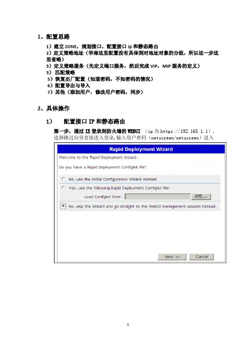
1、配置思路1)建立ZONE,规划接口,配置接口ip和静态路由2)定义策略地址(华南这里配置没有具体到对地址对象的分组,所以这一步这里省略)3)定义策略服务(先定义端口服务,然后完成VIP,MIP服务的定义)3)匹配策略5)恢复出厂配置(知道密码,不知密码的情况)6)配置导出与导入7)其他(添加用户,修改用户密码,同步)2、具体操作1)配置接口IP和静态路由第一步,通过IE登录到防火墙的WEBUI(ip为https://192.168.1.1),选择跳过向导直接进入登录,输入用户密码(netscreen/netscreen)进入第二步、为接口匹配iP(Zones和接口都用系统默认的就够用了,这里只需为接口配相应的IP)进入Network>interfaces界面先编辑eth0/1 的地址:其中Management Services可根管理需求勾选,ping勾上接着编辑eth0/2的地址:这里Management Service 勾上Web UI、Telnet及SSH,Ping也勾上,这样方便以后通过外网来管理防火墙。
最后方法同上修改eth0/0的ip为所要设的IP (华南这里:172.31.11.1/24),这里为方便管理Mangement Service全勾上。
配置完成后,防火墙会自动重启,这时需要重新修改本机的IP与防火墙的eth0/0接口的IP同网段(本机通过连接线连接在eth0/0口)第三步、添加静态路由进入Network > Routing > Destination界面,点击右上角的NEW来新建路由i)添加到internet的缺省路由目标网络:0.0.0.0 0.0.0.0 网关:202.105.115.201ii)同上方式添加一条连通DMZ与内、地区的路由(目标网络172.31.0.0/16 网关:172.31.11.2)iii)同上方式添加一条连通DMZ到总部的路由(目标网络172.17.0.0/16 网关:172.31.11.2)添加完成后如下图示2)定义策略地址(略)3)定义策略服务(先定义端口服务,然后完成VIP,MIP服务的定义)进入Policy > Policy Elements > Services > Custom界面来自定义服务端口第一步、对照之前准备的照服务端口映射表,统计需要定义的端口服务注:此图为端口服务映射表的部分统计的端口有:50000,22000,51000,4489,81,8080,7761,3389,139,4899,4200接着添加定义端口服务,点击右上角新建来定义端口,进入下面的界面:服务名设为端口号,目标端口号因为只有一个,范围的最小最大值都为端口号,这样就定义好了一个端口服务。
防火墙三种部署模式及基本配置Juniper防火墙在实际的部署过程中主要有三种模式可供选择,这三种模式分别是:① 基于TCP/IP协议三层的NAT模式;② 基于TCP/IP协议三层的路由模式;③ 基于二层协议的透明模式。
2.1、NAT模式当Juniper防火墙入口接口(“内网端口”)处于NAT模式时,防火墙将通往Untrust 区(外网或者公网)的IP 数据包包头中的两个组件进行转换:源 IP 地址和源端口号。
防火墙使用 Untrust 区(外网或者公网)接口的 IP 地址替换始发端主机的源IP 地址;同时使用由防火墙生成的任意端口号替换源端口号。
NAT模式应用的环境特征:① 注册IP地址(公网IP地址)的数量不足;② 内部网络使用大量的非注册IP地址(私网IP地址)需要合法访问Internet;③ 内部网络中有需要外显并对外提供服务的服务器。
2.2、Route-路由模式当Juniper防火墙接口配置为路由模式时,防火墙在不同安全区间(例如:Trust/Utrust/DMZ)转发信息流时IP 数据包包头中的源地址和端口号保持不变。
① 与NAT模式下不同,防火墙接口都处于路由模式时,不需要为了允许入站数据流到达某个主机而建立映射 IP (MIP) 和虚拟 IP (VIP) 地址;② 与透明模式下不同,当防火墙接口都处于路由模式时,其所有接口都处于不同的子网中。
路由模式应用的环境特征:① 注册IP(公网IP地址)的数量较多;② 非注册IP地址(私网IP地址)的数量与注册IP地址(公网IP地址)的数量相当;③ 防火墙完全在内网中部署应用。
2.3、透明模式当Juniper防火墙接口处于“透明”模式时,防火墙将过滤通过的IP数据包,但不会修改 IP数据包包头中的任何信息。
防火墙的作用更像是处于同一VLAN 的2 层交换机或者桥接器,防火墙对于用户来说是透明的。
透明模式是一种保护内部网络从不可信源接收信息流的方便手段。
Configuration GuideJuniperNetScreen 5GTWebSite: Contact: ***********************Configuration Guide written by:Writer: Connected TeamCompany: Table of contents1Introduction (3)1.1Goal of this document (3)1.2VPN Network topology (3)1.3Juniper NetScreen 5GT Firewall (3)1.4Juniper NetScreen 5GT Firewall product info (3)2Juniper NetScreen 5GT VPN configuration (4)2.1Create GateWay (4)2.2Set Advanced (4)2.3Create IKE (5)2.4Set Advanced (5)2.5Create VPN policy (5)3TheGreenBow IPSec VPN Client configuration (7)3.1VPN Client Phase 1 (IKE) Configuration (7)3.2VPN Client Phase 2 (IPSec) Configuration (8)3.3Open IPSec VPN tunnels (8)4Tools in case of trouble (9)4.1 A good network analyser: Wireshark (9)5VPN IPSec Troubleshooting (10)5.1« PAYLOAD MALFORMED» error (wrong Phase 1 [SA]) (10)5.2« INVALID COOKIE » error (10)5.3« no keystate » error (10)5.4« received remote ID other than expected » error (10)5.5« NO PROPOSAL CHOSEN » error (11)5.6« INVALID ID INFORMATION » error (11)5.7I clicked on “Open tunnel”, but nothing happens. (11)5.8The VPN tunnel is up but I can’t ping ! (11)6Contacts (13)1 Introduction1.1 Goal of this documentThis configuration guide describes how to configure TheGreenBow IPSec VPN Client software with a Juniper NetScreen 5GT firewall to establish VPN connections for remote access to corporate network1.2 VPN Network topologyIn our VPN network example (diagram hereafter), we will connect TheGreenBow IPSec VPN Client software to the LAN behind the Juniper NetScreen 5GT firewall. The VPN client is connected to the Internet with a DSL connection or through a LAN. All the addresses in this document are given for example purpose.1.3Juniper NetScreen 5GT FirewallOur tests and VPN configuration have been conducted with Juniper NetScreen 5GT firmware release 5.0.0r10.01.4 Juniper NetScreen 5GT Firewall product infoIt is critical that users find all necessary information about Juniper NetScreen 5GT firewall. All product info, User Guide and knowledge base for the Juniper NetScreen 5GT firewall can be found on the juniper website: IPSec VPN Client (Remote) 192.168.10.122192.168.3.3192.168.3.78Netscreen 5GT192.168.3.1192.168.10.20InternetIPSec VPN Client as seen on LAN2Juniper NetScreen 5GT VPN configurationThis section describes how to build an IPSec VPN configuration with your Juniper NetScreen 5GT firewall. Once connected to your Juniper NetScreen 5GT firewall, you must select “VPN” and “GateWay” tabs.2.1Create GateWay2.2Set Advanced2.3Create IKE2.4Set Advanced2.5Create VPN policy Policy from trust to untrust :Policy from untrust to trust :3 TheGreenBow IPSec VPN Client configurationThis section describes the required configuration to connect to a Juniper NetScreen 5GT VPN connections. To download the latest release of TheGreenBow IPSec VPN Client software, please go to /vpn_down.html .3.1 VPN Client Phase 1 (IKE) ConfigurationPhase 1 configurationYou may use either Preshared key, Certificates, USB Tokens, OTP Token (One Time Password) or X-Auth combined with RADIUS Server for User Authentication with the Juniper NetScreen 5GT firewall. This configuration is one example of what can be accomplished in term of User Authentication. You may want to refer to either the Juniper NetScreen 5GT firewall user guide or TheGreenBow IPSec VPN Client software User Guide for more details on User Authentication options.01234567893.2 VPN Client Phase 2 (IPSec) ConfigurationPhase 2 Configuration3.3 Open IPSec VPN tunnelsOnce both Juniper NetScreen 5GT firewall and TheGreenBow IPSec VPN Client software have been configured accordingly, you are ready to open VPN tunnels. First make sure you enable your firewall with IPSec traffic. 1. Click on "Save & Apply " to take into account all modifications we've made on your VPN Client configuration 2. Click on "Open Tunnel ", or generate traffic that will automatically open a secure IPSec VPN Tunnel (e.g. ping, IE browser)3. Select "Connections " to see opened VPN Tunnels4. Select "Console " if you want to access to the IPSec VPN logs and adjust filters to display less IPSec messaging. The following example shows a successful connection between TheGreenBow IPSec VPN Client and a Juniper NetScreen 5GT VPN router.VPN Client Virtual IPaddressEnter the IP address (and subnet mask) of the remote LAN.4Tools in case of troubleConfiguring an IPSec VPN tunnel can be a hard task. One missing parameter can prevent a VPN connection from being established. Some tools are available to find source of troubles during a VPN establishment.4.1 A good network analyser: WiresharkWireshark is a free software that can be used for packet and traffic analysis. It shows IP or TCP packets received on a network card. This tool is available on website . It can be used to follow protocol exchange between two devices. For installation and use details, read its specific documentation (/docs/).5VPN IPSec Troubleshooting5.1« PAYLOAD MALFORMED» error (wrong Phase 1 [SA])114920 Default (SA CNXVPN1-P1) SEND phase 1 Main Mode [SA][VID]114920 Default (SA CNXVPN1-P1) RECV phase 1 Main Mode [NOTIFY]114920 Default exchange_run: exchange_validate failed114920 Default dropped message from 195.100.205.114 port 500 due to notification type PAYLOAD_MALFORMED114920 Default SEND Informational [NOTIFY] with PAYLOAD_MALFORMED errorIf you have an « PAYLOAD MALFORMED » error you might have a wrong Phase 1 [SA], check if the encryption algorithms are the same on each side of the VPN tunnel.5.2« INVALID COOKIE » error115933 Default message_recv: invalid cookie(s) 5918ca0c2634288f 7364e3e486e49105 115933 Default dropped message from 195.100.205.114 port 500 due to notification type INVALID_COOKIE115933 Default SEND Informational [NOTIFY] with INVALID_COOKIE errorIf you have an « INVALID COOKIE » error, it means that one of the endpoint is using a SA that is no more in use. Reset the VPN connection on each side.5.3« no keystate » error115315 Default (SA CNXVPN1-P1) SEND phase 1 Main Mode [SA][VID]115317 Default (SA CNXVPN1-P1) RECV phase 1 Main Mode [SA][VID]115317 Default (SA CNXVPN1-P1) SEND phase 1 Main Mode [KEY][NONCE]115319 Default (SA CNXVPN1-P1) RECV phase 1 Main Mode [KEY][NONCE]115319 Default (SA CNXVPN1-P1) SEND phase 1 Main Mode [ID][HASH][NOTIFY]115319 Default ipsec_get_keystate: no keystate in ISAKMP SA 00B57C50Check if the preshared key is correct or if the local ID is correct (see « Advanced » button). You should have more information in the remote endpoint logs.5.4« received remote ID other than expected » error120348 Default (SA CNXVPN1-P1) SEND phase 1 Main Mode [SA][VID]120349 Default (SA CNXVPN1-P1) RECV phase 1 Main Mode [SA][VID]120349 Default (SA CNXVPN1-P1) SEND phase 1 Main Mode [KEY][NONCE]120351 Default (SA CNXVPN1-P1) RECV phase 1 Main Mode [KEY][NONCE]120351 Default (SA CNXVPN1-P1) SEND phase 1 Main Mode [ID][HASH][NOTIFY]120351 Default (SA CNXVPN1-P1) RECV phase 1 Main Mode [ID][HASH][NOTIFY]120351 Default ike_phase_1_recv_ID: received remote ID other than expected **********************The « Remote ID » value (see « Advanced » Button) does not match what the remote endpoint is expected.5.5« NO PROPOSAL CHOSEN » error115911 Default (SA CNXVPN1-P1) SEND phase 1 Main Mode [SA][VID]115913 Default (SA CNXVPN1-P1) RECV phase 1 Main Mode [SA][VID]115913 Default (SA CNXVPN1-P1) SEND phase 1 Main Mode [KEY][NONCE]115915 Default (SA CNXVPN1-P1) RECV phase 1 Main Mode [KEY][NONCE]115915 Default (SA CNXVPN1-P1) SEND phase 1 Main Mode [ID][HASH][NOTIFY]115915 Default (SA CNXVPN1-P1) RECV phase 1 Main Mode [ID][HASH][NOTIFY]115915 Default phase 1 done: initiator id c364cd70: 195.100.205.112, responder id c364cd72: 195.100.205.114, src: 195.100.205.112 dst: 195.100.205.114115915 Default (SA CNXVPN1-CNXVPN1-P2) SEND phase 2 Quick Mode [SA][KEY][ID][HASH][NONCE]115915 Default RECV Informational [HASH][NOTIFY] with NO_PROPOSAL_CHOSEN error 115915 Default RECV Informational [HASH][DEL]115915 Default CNXVPN1-P1 deletedIf you have an « NO PROPOSAL CHOSEN » error, check that the « Phase 2 » encryption algorithms are the same on each side of the VPN Tunnel.Check « Phase 1 » algorithms if you have this:115911 Default (SA CNXVPN1-P1) SEND phase 1 Main Mode [SA][VID]115911 Default RECV Informational [NOTIFY] with NO_PROPOSAL_CHOSEN error5.6« INVALID ID INFORMATION » error122623 Default (SA CNXVPN1-P1) SEND phase 1 Main Mode [SA][VID]122625 Default (SA CNXVPN1-P1) RECV phase 1 Main Mode [SA][VID]122625 Default (SA CNXVPN1-P1) SEND phase 1 Main Mode [KEY][NONCE]122626 Default (SA CNXVPN1-P1) RECV phase 1 Main Mode [KEY][NONCE]122626 Default (SA CNXVPN1-P1) SEND phase 1 Main Mode [ID][HASH][NOTIFY]122626 Default (SA CNXVPN1-P1) RECV phase 1 Main Mode [ID][HASH][NOTIFY]122626 Default phase 1 done: initiator id c364cd70: 195.100.205.112, responder id c364cd72: 195.100.205.114, src: 195.100.205.112 dst: 195.100.205.114122626 Default (SA CNXVPN1-CNXVPN1-P2) SEND phase 2 Quick Mode [SA][KEY][ID][HASH][NONCE]122626 Default RECV Informational [HASH][NOTIFY] with INVALID_ID_INFORMATION error 122626 Default RECV Informational [HASH][DEL]122626 Default CNXVPN1-P1 deletedIf you have an « INVALID ID INFORMATION » error, check if « Phase 2 » ID (local address and network address) is correct and match what is expected by the remote endpoint.Check also ID type (“Subnet address” and “Single address”). If network mask is not check, you are using a IPV4_ADDR type (and not a IPV4_SUBNET type).5.7I clicked on “Open tunnel”, but nothing happens.Read logs of each VPN tunnel endpoint. IKE requests can be dropped by firewalls. An IPSec Client uses UDP port 500 and protocol ESP (protocol 50).5.8The VPN tunnel is up but I can’t ping !If the VPN tunnel is up, but you still cannot ping the remote LAN, here are a few guidelines:•Check Phase 2 settings: VPN Client address and Remote LAN address. Usually, VPN Client IP address should not belong to the remote LAN subnet•Once VPN tunnel is up, packets are sent with ESP protocol. This protocol can be blocked by firewall.Check that every device between the client and the VPN server does accept ESP•Check your VPN server logs. Packets can be dropped by one of its firewall rules.•Check your ISP support ESP•If you still cannot ping, follow ICMP traffic on VPN server LAN interface and on LAN computer interface (with Wireshark for example). You will have an indication that encryption works.•Check the “default gateway” value in VPN Server LAN. A target on your remote LAN can receive pings but does not answer because there is a no “Default gateway” setting.•You cannot access to the computers in the LAN by their name. You must specify their IP address inside the LAN.•We recommend you to install Wireshark () on one of your target computer. You can check that your pings arrive inside the LAN.6ContactsNews and updates on TheGreenBow web site: Technical support by email at ***********************Sales contacts by email at *********************Secure, Strong, Simple. TheGreenBow Security Software。
Juniper SRX系列防火墙配置管理手册目录一、JUNOS操作系统介绍 (3)1.1 层次化配置结构 (3)1.2 JunOS配置管理 (4)1.3 SRX主要配置内容 (4)二、SRX防火墙配置操作举例说明 (5)2.1 初始安装 (5)2.1.1 设备登陆 (5)2.1.2 设备恢复出厂介绍 (5)2.1.3 设置root用户口令 (5)2.1.4 设置远程登陆管理用户 (6)2.1.5 远程管理SRX相关配置 (6)2.2 配置操作实验拓扑 (7)2.3 策略相关配置说明 (7)2.3.1 策略地址对象定义 (8)2.3.2 策略服务对象定义 (8)2.3.3 策略时间调度对象定义 (8)2.3.4 添加策略配置举例 (9)2.3.5 策略删除 (10)2.3.6 调整策略顺序 (10)2.3.7 策略失效与激活 (10)2.4 地址转换 (10)2.4.1 Interface based NAT 基于接口的源地址转换 (11)2.4.2 Pool based Source NAT基于地址池的源地址转换 (12)2.4.3 Pool base destination NAT基于地址池的目标地址转换 (12)2.4.4 Pool base Static NAT基于地址池的静态地址转换 (13)2.5 路由协议配置 (14)静态路由配置 (14)OSPF配置 (15)交换机Firewall限制功能 (22)限制IP地 (22)限制MAC地址 (22)三、SRX防火墙常规操作与维护 (23)3.2设备关机 (23)3.3设备重启 (23)3.4操作系统升级 (24)3.5密码恢复 (25)3.6常用监控维护命令 (26)Juniper SRX Branch系列防火墙配置管理手册说明SRX系列防火墙是Juniper公司基于JUNOS操作系统的安全系列产品,JUNOS集成了路由、交换、安全性和一系列丰富的网络服务。
juniper netscreen ssg5gt防火墙傻瓜配置说明书一、防火墙的基本设置1、防火墙程序的重装如果防火墙出现故障,需要重装程序或重新配置,可以采用超级终端,先清空程序,再进行安装。
具体操作为:第一步:用9针数据线(防火墙有带)连接防火墙和电脑(下图画红线端口),打开电源。
第二步:打开程序—附件—通讯—超级终端(下图),第四步:打开超级终端出现下图,随便填写连接名称,按确定,第五步:确定后出现下图,“连接使用”选择COM1,其它不填第六步:再确定后出现下图,第七步:再按确定,就出现名为“1111”的超级终端第八步:当防火墙接上电脑后,超级终端就会出现login: ,如果要重装软件,就输入防火墙产品背面的序列号,本公司使用的产品序列号为0064092004011007,再按回车,出现password: ,再输入序列号,回车,就出现重启画面。
下图红线部分是询问是否重启y/n,键盘输入y,回车,自动重启,防火墙恢复到出厂设置,web入口为192.168.1.1:第九步:把防火墙拆下,通过网络线放入到服务器端(或者用网络线与任意一机器相连都行,但机器的本地连接要与防火墙同一网段,即网关设为192.168.1.1),接上电源,然后打开IE,输入http://192.168.1.1,就可登录防火墙首页,然后进行防火墙的基本程序重装。
2、防火墙程序重装第一步:打开IE,输入http://192.168.1.1,可见下图第二步:直接按“下一步”,出现下图第三步:再按next ,出现下图。
可以自定义用户名和密码(现在防火墙上设置的用户名为netscreen ,密码为hai2DA ),第四步:然后再按next,可见下图第五步:选中“Enable Nat ”,按“next ”,出现下图第六步:选择“trust-untrust Mode”,按“next”,可见下图第七步:因为我们的是固定外网IP,选中“static IP”,在“untrust zone interface IP(即:非信任区入口IP)”填写入外网IP:121.40.245.10;在netmask(子网掩码)填写入:255.255.255.0;在gateway(网关)中填写入:121.40.245.1。
Juniper netscreen 防火墙三种部署模式及基本配置Juniper防火墙在实际的部署过程中主要有三种模式可供选择,这三种模式分别是:① 基于TCP/IP协议三层的NAT模式;② 基于TCP/IP协议三层的路由模式;③ 基于二层协议的透明模式。
2.1、NAT模式当Juniper防火墙入口接口(内网端口)处于NAT模式时,防火墙Juniper防火墙在实际的部署过程中主要有三种模式可供选择,这三种模式分别是:① 基于TCP/IP协议三层的NAT模式;② 基于TCP/IP协议三层的路由模式;③ 基于二层协议的透明模式。
2.1、NAT模式当Juniper防火墙入口接口(“内网端口”)处于NAT模式时,防火墙将通往 Untrust 区(外网或者公网)的IP 数据包包头中的两个组件进行转换:源 IP 地址和源端口号。
防火墙使用 Untrust 区(外网或者公网)接口的 IP 地址替换始发端主机的源 IP 地址;同时使用由防火墙生成的任意端口号替换源端口号。
NAT模式应用的环境特征:① 注册IP地址(公网IP地址)的数量不足;② 内部网络使用大量的非注册IP地址(私网IP地址)需要合法访问Internet;③ 内部网络中有需要外显并对外提供服务的服务器。
2.2、Route-路由模式当Juniper防火墙接口配置为路由模式时,防火墙在不同安全区间(例如:Trust/Utrust/DMZ)转发信息流时IP 数据包包头中的源地址和端口号保持不变。
① 与NAT模式下不同,防火墙接口都处于路由模式时,不需要为了允许入站数据流到达某个主机而建立映射 IP (MIP) 和虚拟 IP (VIP) 地址;② 与透明模式下不同,当防火墙接口都处于路由模式时,其所有接口都处于不同的子网中。
路由模式应用的环境特征:① 注册IP(公网IP地址)的数量较多;② 非注册IP地址(私网IP地址)的数量与注册IP地址(公网IP地址)的数量相当;③ 防火墙完全在内网中部署应用。
2.3、透明模式当Juniper防火墙接口处于“透明”模式时,防火墙将过滤通过的IP数据包,但不会修改 IP 数据包包头中的任何信息。
防火墙的作用更像是处于同一VLAN的2 层交换机或者桥接器,防火墙对于用户来说是透明的。
透明模式是一种保护内部网络从不可信源接收信息流的方便手段。
使用透明模式有以下优点:① 不需要修改现有网络规划及配置;② 不需要为到达受保护服务器创建映射或虚拟 IP 地址;③ 在防火墙的部署过程中,对防火墙的系统资源消耗最低。
2.4、基于向导方式的NAT/Route模式下的基本配置Juniper防火墙NAT和路由模式的配置可以在防火墙保持出厂配置启动后通过Web浏览器配置向导完成。
注:要启动配置向导,则必须保证防火墙设备处于出厂状态。
例如:新的从未被调试过的设备,或者经过命令行恢复为出厂状态的防火墙设备。
通过Web浏览器登录处于出厂状态的防火墙时,防火墙的缺省管理参数如下:① 缺省IP:192.168.1.1/255.255.255.0;② 缺省用户名/密码:netscreen/ netscreen;注:缺省管理IP地址所在端口参见在前言部份讲述的“Juniper防火墙缺省管理端口和IP地址”中查找!!在配置向导实现防火墙应用的同时,我们先虚拟一个防火墙设备的部署环境,之后,根据这个环境对防火墙设备进行配置。
防火墙配置规划:① 防火墙部署在网络的Internet出口位置,内部网络使用的IP地址为192.168.1.0/255.255.255.0所在的网段,内部网络计算机的网关地址为防火墙内网端口的IP地址:192.168.1.1;② 防火墙外网接口IP地址(通常情况下为公网IP地址,在这里我们使用私网IP地址模拟公网IP地址)为:10.10.10.1/255.255.255.0,网关地址为:10.10.10.251要求:实现内部访问Internet的应用。
注:在进行防火墙设备配置前,要求正确连接防火墙的物理链路;调试用的计算机连接到防火墙的内网端口上。
1. 通过IE或与IE兼容的浏览器(推荐应用微软IE浏览器)使用防火墙缺省IP地址登录防火墙(建议:保持登录防火墙的计算机与防火墙对应接口处于相同网段,直接相连)。
2. 使用缺省IP登录之后,出现安装向导:注:对于熟悉Juniper防火墙配置的工程师,可以跳过该配置向导,直接点选:No,skip the wizard and go straight to the WebUI management session instead,之后选择Next,直接登录防火墙设备的管理界面。
3. 使用向导配置防火墙,请直接选择:Next,弹出下面的界面:4. “欢迎使用配置向导”,再选择Next。
注:进入登录用户名和密码的修改页面,Juniper防火墙的登录用户名和密码是可以更改的,这个用户名和密码的界面修改的是防火墙设备上的根用户,这个用户对于防火墙设备来说具有最高的权限,需要认真考虑和仔细配置,保存好修改后的用户名和密码。
5. 在完成防火墙的登录用户名和密码的设置之后,出现了一个比较关键的选择,这个选择决定了防火墙设备是工作在路由模式还是工作在NAT模式:选择Enable NAT,则防火墙工作在NAT模式;不选择Enable NAT,则防火墙工作在路由模式。
6. 防火墙设备工作模式选择,选择:Trust-Untrust Mode模式。
这种模式是应用最多的模式,防火墙可以被看作是只有一进一出的部署模式。
注:NS-5GT防火墙作为低端设备,为了能够增加低端产品应用的多样性,Juniper在NS-5GT 的OS中独立开发了几种不同的模式应用于不同的环境。
目前,除NS-5GT以外,Juniper其他系列防火墙不存在另外两种模式的选择。
7. 完成了模式选择,点击“Next”进行防火墙外网端口IP配置。
外网端口IP配置有三个选项分别是:DHCP自动获取IP地址;通过PPPoE拨号获得 IP地址;手工设置静态IP地址,并配置子网掩码和网关IP地址。
在这里,我们选择的是使用静态IP地址的方式,配置外网端口IP地址为:10.10.10.1/255.255.255.0,网关地址为:10.10.10.251。
8.完成外网端口的IP地址配置之后,点击“Next”进行防火墙内网端口IP配置:9. 在完成了上述的配置之后,防火墙的基本配置就完成了,点击“Next”进行DHCP服务器配置。
注:DHCP服务器配置在需要防火墙在网络中充当DHCP服务器的时候才需要配置。
否则请选择“NO”跳过。
注:上面的页面信息显示的是在防火墙设备上配置实现一个DHCP服务器功能,由防火墙设备给内部计算机用户自动分配IP地址,分配的地址段为:192.168.1.100-192.168.1.150一共51个IP地址,在分配IP地址的同时,防火墙设备也给计算机用户分配了DNS服务器地址,DNS用于对域名进行解析,如:将错误!超链接引用无效。
地址:202.108.33.32。
如果计算机不能获得或设置DNS服务器地址,无法访问互联网。
10. 完成DHCP服务器选项设置,点击“Next”会弹出之前设置的汇总信息:11. 确认配置没有问题,点击“Next”会弹出提示“Finish”配置对话框:在该界面中,点选:Finish之后,该Web页面会被关闭,配置完成。
此时防火墙对来自内网到外网的访问启用基于端口地址的NAT,同时防火墙设备会自动在策略列表部分生成一条由内网到外网的访问策略:策略:策略方向由Trust到Untrust,源地址:ANY,目标地址:ANY,网络服务内容:ANY;策略作用:允许来自内网的任意IP地址穿过防火墙访问外网的任意地址。
重新开启一个IE页面,并在地址栏中输入防火墙的内网端口地址,确定后,出现下图中的登录界面。
输入正确的用户名和密码,登录到防火墙之后,可以对防火墙的现有配置进行修改。
总结:上述就是使用Web浏览器通过配置向导完成的防火墙NAT或路由模式的应用。
通过配置向导,可以在不熟悉防火墙设备的情况下,配置简单环境的防火墙应用。
2.5、基于非向导方式的NAT/Route模式下的基本配置基于非向导方式的NAT和Route模式的配置建议首先使用命令行开始,最好通过控制台的方式连接防火墙,这个管理方式不受接口IP地址的影响。
注:在设备缺省的情况下,防火墙的信任区(Trust Zone)所在的端口是工作在NAT模式的,其它安全区所在的端口是工作在路由模式的。
基于命令行方式的防火墙设备部署的配置如下(网络环境同上一章节所讲述的环境):2.5.1、NS-5GT NAT/Route模式下的基本配置注:NS-5GT设备的物理接口名称叫做trust和untrust;缺省Zone包括:trust和untrust,请注意和接口区分开。
① Unset interface trust ip (清除防火墙内网端口的IP地址);② Set interface trust zone trust(将内网端口分配到trust zone);③ Set interface trust ip 192.168.1.1/24(设置内网端口的IP地址,必须先定义zone,之后再定义IP地址);④ Set interface untrust zone untrust(将外网口分配到untrust zone);⑤ Set interface untrust ip 10.10.10.1/24(设置外网口的IP地址);⑥ Set route 0.0.0.0/0 interface untrust gateway 10.10.10.251(设置防火墙对外的缺省路由网关地址);⑦ Set policy from trust to untrust any any any permit log(定义一条由内网到外网的访问策略。
策略的方向是:由zone trust 到 zone untrust,源地址为:any,目标地址为:any,网络服务为:any,策略动作为:permit允许,log:开启日志记录);⑧ Save (保存上述的配置文件)。
2.5.2、NS-25-208 NAT/Route模式下的基本配置① Unset interface ethernet1 ip(清除防火墙内网口缺省IP地址);② Set interface ethern et1 zone trust(将ethernet1端口分配到trust zone);③ Set interface ethernet1 ip 192.168.1.1/24(定义ethernet1端口的IP地址);④ Set interface ethernet3 zone untrust(将ethernet3端口分配到untrust zone);⑤ Set interface ethernet3 ip 10.10.10.1/24(定义ethernet3端口的IP地址);⑥ Set route 0.0.0.0/0 interface ethernet3 gateway 10.10.10.251(定义防火墙对外的缺省路由网关);⑦ Set policy from trust to untrust any any any permit log(定义由内网到外网的访问控制策略);⑧ Save (保存上述的配置文件)注:上述是在命令行的方式上实现的NAT模式的配置,因为防火墙出厂时在内网端口(trust zone所属的端口)上启用了NAT,所以一般不用特别设置,但是其它的端口则工作在路由模式下,例如:untrust和DMZ区的端口。