Threshold open charm production in nucleon-nucleon collisions
- 格式:pdf
- 大小:153.65 KB
- 文档页数:10

火焰几何特征提取python在Python中,你可以使用各种库来进行火焰几何特征提取。
通常,你需要使用计算机视觉或图像处理库来处理火焰图像并提取几何特征。
下面是一个简单的示例,使用OpenCV库:```pythonimport cv2import numpy as npdef extract_flame_geometry(image_path):# 读取图像image = cv2.imread(image_path)# 转换图像为灰度gray = cv2.cvtColor(image, cv2.COLOR_BGR2GRAY)# 使用阈值分割图像_, binary = cv2.threshold(gray, 127, 255, cv2.THRESH_BINARY)# 寻找轮廓contours, _ = cv2.findContours(binary, cv2.RETR_EXTERNAL, cv2.CHAIN_APPROX_SIMPLE)# 提取轮廓特征for contour in contours:# 计算轮廓的面积area = cv2.contourArea(contour)# 计算轮廓的周长perimeter = cv2.arcLength(contour, True)# 计算轮廓的凸包hull = cv2.convexHull(contour)# 绘制凸包cv2.drawContours(image, [hull], 0, (0, 255, 0), 2)# 显示特征信息print(f"Area: {area}, Perimeter: {perimeter}")# 显示结果图像cv2.imshow("Flame Geometry", image)cv2.waitKey(0)cv2.destroyAllWindows()# 使用示例image_path = "path/to/your/flame/image.jpg"extract_flame_geometry(image_path)```请确保安装了OpenCV库:```bashpip install opencv-python```这个简单的例子中,我们首先读取图像,将其转换为灰度图像,并使用阈值分割。
刚用ae的时候,看着那一大堆的英文头都大了,没办法,谁叫咋英文忒烂呢,但是,事情总是有人来解决滴,要想对ae运用自如,那还等什么,把下面的单词记下来吧!一,Adjust主要都是一些调整参数的滤镜,主要包括以下滤镜:01,Brightness&Contrast用于调整亮度和对比度02,Channel MixerChannel Mixer用于通道混合,可以用当前彩色通道的值来修改一个彩色通道。
应用Channel Mixer可以产生其它颜色调整工具不易产生的效果;或者通过设置每个通道提供的百分比产生高质量的灰阶图;或者产生高质量的棕色调和其它色调图像;或者交换和复制通道。
Red/Green/Blue-Red/Green/BIue/Const分别表不不同的颜色调整通道,Const用来调整通道的对比度。
参数以百分比表示,表明增强或减弱该通道的效果。
其默认的参数为Red-Red Green-Green Blue-Blue都是1O0%,其它为O%,表示初始的RGB通道值。
最下方的Monochrome选项是可以将图像应用为灰阶图03,Color BalanceColor Balance用于调整色彩平衡。
通过调整层中包含的红、绿、蓝的颜色值,颜色平衡. 效果控制参数Shadow Red/Blue/Green Balance用于调整RGB彩色的阴影范围平衡。
Midtone Red/BIue/Green Balance用于调整RGB彩色的中问亮度范围平衡。
Hilight Red /Blue/Green Balance用于调整RGB彩色的高光范围平衡。
Preserve Luminosity选项用于保持图像的平均亮度,来保持图像的整体平衡。
04,CurvesCurves用于调整图象的色调曲线,通过改变效果窗口的Curves曲线来改变图象的色调。
也可以用Level完成同样的工作,但是Curves的控制能力更强。
05,Channel用于选择要进行调控的通道,可以选RGB彩色通道,Red红色通道、Green绿色通道、Bule 蓝色通道和Alpha透明通道分别进行调控。
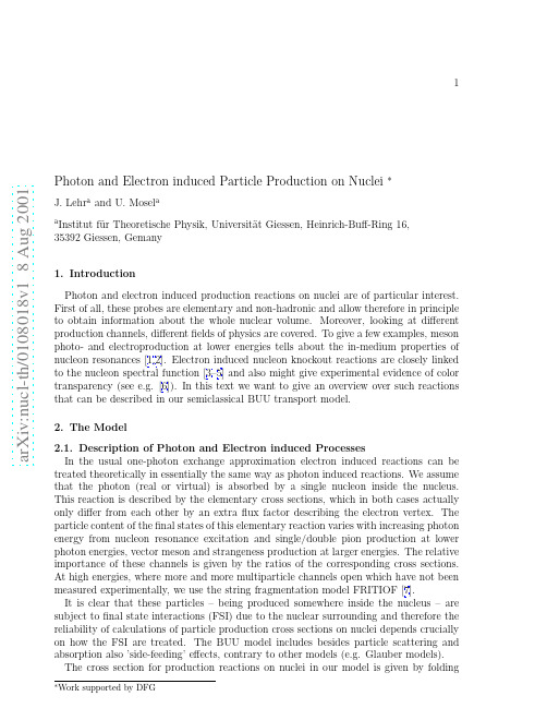
a rXiv:n ucl-t h /1818v18Aug211Photon and Electron induced Particle Production on Nuclei ∗J.Lehr a and U.Mosel a a Institut f¨u r Theoretische Physik,Universit¨a t Giessen,Heinrich-Buff-Ring 16,35392Giessen,Gemany 1.Introduction Photon and electron induced production reactions on nuclei are of particular interest.First of all,these probes are elementary and non-hadronic and allow therefore in principle to obtain information about the whole nuclear volume.Moreover,looking at different production channels,different fields of physics are covered.To give a few examples,meson photo-and electroproduction at lower energies tells about the in-medium properties of nucleon resonances [1,2].Electron induced nucleon knockout reactions are closely linked to the nucleon spectral function [3–5]and also might give experimental evidence of color transparency (see e.g.[6]).In this text we want to give an overview over such reactions that can be described in our semiclassical BUU transport model.2.The Model 2.1.Description of Photon and Electron induced Processes In the usual one-photon exchange approximation electron induced reactions can betreated theoretically in essentially the same way as photon induced reactions.We assume that the photon (real or virtual)is absorbed by a single nucleon inside the nucleus.This reaction is described by the elementary cross sections,which in both cases actually only differ from each other by an extra flux factor describing the electron vertex.The particle content of the final states of this elementary reaction varies with increasing photon energy from nucleon resonance excitation and single/double pion production at lower photon energies,vector meson and strangeness production at larger energies.The relative importance of these channels is given by the ratios of the corresponding cross sections.At high energies,where more and more multiparticle channels open which have not been measured experimentally,we use the string fragmentation model FRITIOF [7].It is clear that these particles –being produced somewhere inside the nucleus –are subject to final state interactions (FSI)due to the nuclear surrounding and therefore the reliability of calculations of particle production cross sections on nuclei depends crucially on how the FSI are treated.The BUU model includes besides particle scattering and absorption also ’side-feeding’effects,contrary to other models (e.g.Glauber models).The cross section for production reactions on nuclei in our model is given by folding2the cross sections of the elementary reaction on the nucleon and the multiplicity of the particles under consideration reaching the detector and an incoherent summation of the contributions from all nucleons in the nucleus[2].2.2.The BUU ModelThe model is based upon the BUU2equation,which for a system of nucleons is given by∂∂ p∇r f( r, p,t)−∂HNiδ( p− p i)δ( r− r i).(2)For the propagation of the test particles this ansatz gives the classical equations of motion ˙ ri= ∇p H,˙ p i=− ∇r H.(3) 3.Results3.1.Meson ProductionPion and eta production in the nucleon resonance region was calculated and discussed in detail in[1,2].The applicability of the model extends also to larger photon energies. However,for Eγ>1GeV the so-called shadowing effect has to be taken into account. Since this is a coherence effect,it cannot be simulated in a semi-classical transport model. In[8]a procedure was developed to combine the description of these initial state interac-tions in the Glauber framework with the usual BUU model.Also the calculation of meson photoproduction at GeV energies can be found there.3.2.Electron induced Nucleon KnockoutThe electron induced nucleon knockout from nuclei(for a review see e.g.[9])is of special interest since it might give experimental evidence for color transparency.The data from SLAC[10]and TJNAF[11]show the so-called transparency ratio which is given by the ratio of the number of protons measured close to the direction of the exchanged virtual photon and the expected number of protons in the absence of FSI.Our model is capable3Figure1.(open).to the latter number.the past(see e.g.[6,12]andIn Fig.transfer Q2.For both Future work willalso cover[10,11],where an onset of color transparency is expected and consequently an enhancement of T towardsone.Moreover,the influence of the nucleon spectral function on T will be investigated.3.3.Nucleon Spectral Function and Subthreshold Particle Production Nucleons in nuclei may be offtheir mass shell in the nuclear groundstate due to short-range correlations(see e.g.[3–5]).Calculations of the nucleon spectral functions show that these groundstate correlations manifest themselves e.g.in the momentum distribu-tion.The Thomas-Fermi momentum distribution(usually used by transport models to initialize the nucleon phase space density in momentum space)is a step functionΘ(p F−p). The effect of the short-range correlations is that some strength(∼10%)is moved frommomenta below p F to momenta above p F.The presence of short-range correlations has an influence on the particle production close to threshold.This can be seen in Fig.2,where the center-of-mass energy distribution for theγN system involving all nucleons in Calcium is shown for Eγ=0.8GeV.The solid curve shows the distribution caused by usual Fermi motion involving on-shell nucleons.The dashed distribution,involving the full nucleon spectral function,is more smeared out√s expected in the and exhibits contributions forThomas-Fermi model.This is the region responsible for subthreshold particle productioneffects.In order to perform such calculations,our model has to be modified,because the nucleon phase space density has to be initialized differently than usual and the off-shellness of the nucleons evolves during the reaction.The latter fact is reflected in a modification of the equations of motion for the test particles.A theoretical discussion of4Figure2.these be found in[13].A numerical for the description of heavy for future work on the4.Summary and OutlookWe have presented several examples for the calculation of inclusive particle production on nuclei within our semi-classical BUU transport model.Future work will cover the extension of our calculations of(e,e′p)to larger Q2and photon induced reactions involving the nucleon spectral function.REFERENCES1.M.Effenberger et al.,Nucl.Phys.A614,501(1997).2.J.Lehr,M.Effenberger and U.Mosel,Nucl.Phys.A671,503(2000).3.O.Benhar,A.Fabrocini and S.Fantoni,Nucl.Phys.A550,201(1992).4. C.Ciofidegli Atti and S.Simula,Phys.Rev.C53,1689(1996).5.J.Lehr et al.,Phys.Lett.B483,324(2000).6.L.Frankfurt,ler and M.Strikman,Ann.Rev.Nucl.Part.Sci.45,501(1994).7. B.Andersson,G.Gustafson and H.Pi,Z.Phys.C57,485(1993).8.M.Effenberger and U.Mosel,Phys.Rev.C62,014605(2000).9.S.Frullani and J.Mougey,Adv.Nucl.Phys.14,1(1984).10.T.O’Neill et al.,Phys.Lett.B351,87(1995).11.D.Abbott et al.,Phys.Rev.Lett.80,5072(1998).12.Y.Golubeva et al.,Phys.Rev.C57,2618(1998).13.S.Leupold,Nucl.Phys.A672,475(2000).14.M.Effenberger and U.Mosel,Phys.Rev.C60,051901(1999).。

©2018 QIAGEN Beverly, Inc. 100 Cummings Center Suite 407J Beverly, MA 01915 Quantabio brand products are manufactured by QIAGEN Beverly, Inc.Intended for molecular biology applications. This product is not intended for the diagnosis, prevention or treatment of a disease.95139 / IFU-095.1 REV 02PerfeC T a ® qPCR ToughMix ® UNG ROX ™DescriptionPerfeC T a qPCR ToughMix UNG ROX is a 2X concentrated ready-to-use reaction cocktail for PCR amplification of DNA templates that overcomes many known inhibitors of PCR often present in crude samples extracted from environmental specimens, plant tissues, or animal tissues. It is a versatile and robust real-time qPCR reagent that provides maximum sensitivity and PCR efficiency with a variety of fluorogenic probe chemistries, including TaqMan ® hydrolysis probes. PerfeC T a qPCR ToughMix UNG ROX contains all required reaction components, except primers, probe(s), and DNA template. Inclusion of uracil DNA glycosylase (UNG), and substitution of dTTP with dUTP, prevents amplification of carry-over contamination from previous dU-containing PCRs.A key component of PerfeC T a qPCR ToughMix UNG ROX is an ultra pure, highly processive thermostable DNA polymerase that is combined with high avidity monoclonal antibodies. This proprietary polymerase mix is highly resistant to PCR inhibitors and provides an extremely stringent automatic hot-start allowing reaction assembly, and temporary storage, at room temperature prior to PCR amplification. PerfeC T a qPCR ToughMix UNG ROX delivers exceptional performance with either fast or conventional PCR cycling protocols.Instrument CompatibilityDifferent real-time PCR systems employ different strategies for the normalization of fluorescent signals and correction of well-to-well optical variations. It is important to match the appropriate reference dye to each specific optical detection system. PerfeCta qPCR ToughMix, ROX contains an optimal concentration of a stabilized carboxy-X-rhodamine compound (ROX ™) for instruments that use an excitation wavelength of ~490 nm and 605 to 610 nm emission channel for the reference signal. Please consult our Product Finder selection tool at to find the correct product for your real-time PCR system. ComponentsPerfeC T a qPCR ToughMix UNG ROX (2X): 2X concentrated reaction buffer containing optimized concentrations of MgCl 2, dNTPs (dATP, dCTP, dGTP,dUTP), hot-start DNA polymerase, uracil DNA glycosylase (UNG), and stabilizers.Storage and StabilityStore components in a constant temperature freezer at -25°C to -15°C protected from light upon receipt. Repeated freezing and thawing does not impair product performance. After thawing, mix thoroughly before using.For lot specific expiry date, refer to package label, Certificate of Analysis or Product Specification Form.Guidelines for qPCR:▪ The design of highly specific primers and probes is a critical parameter for successful real-time PCR. The use of computer aided primer design programs is encouraged in order to minimize the potential for internal secondary stru cture and complementation at 3’-ends within each primer, the primer pair, and primer/probe combinations. For best results, amplicon size should be limited to 65 - 200 bp. Optimal results may require titration of primer concentration between 100 and 900 nM. A final concentration of 300 - 400 nM each primer and 100 to 250 nM probe is effective for most applications. Increasing the concentration of the primer that initiates synthesis of the target strand that is complementary to the probe can improve fluorescent signal for some primer/probe systems.▪ Preparation of a reaction cocktail is recommended to reduce pipetting errors and maximize assay precision. Assemble the reaction cocktail with all required components except sample template (genomic DNA or cDNA) and dispense equal aliquots into each reaction tube. Add the DNA template to each reaction as the final step. Addition of samples as 2 to 5- L volumes will improve assay precision.▪ Suggested input quantities of template are: cDNA corresponding to 1 pg to 100 ng of total RNA; 10 pg to 1 µg genomic DNA▪ After sealing each reaction, vortex gently to mix contents. Centrifuge briefly to collect components at the bottom of the reaction tube. Reaction AssemblyComponentVolume for 20-μL rxn.Final ConcentrationPerfeC T a qPCR ToughMix UNG ROX (2X) 10 µL 1xForward primer variable 100 – 900 nM Reverse primer variable 100 – 900 nM Probevariable 100 – 250 nMNuclease-free water variable Template2 – 5 µL variable Final Volume (μL)20 µLNote : For smaller or larger reaction volumes scale all components proportionally.Cat No. 95139-250 Size: 250 x 20-uL reactions (2 x 1.25 mL) Store at -25ºC to - 15°C protected from light95139-012 1250 x 20-µL reactions (10 x 1.25 mL)95139-05K5000 x 20-µL reactions (1 x 50 mL)©2018 QIAGEN Beverly, Inc. 100 Cummings Center Suite 407J Beverly, MA 01915 Quantabio brand products are manufactured by QIAGEN Beverly, Inc.Intended for molecular biology applications. This product is not intended for the diagnosis, prevention or treatment of a disease.95139 / IFU-095.1 REV 02PCR Cycling ProtocolFast 2-Step Cycling Fast 3-Step Cycling Standard Cycling UNG carry-over incubation – optional:Initial denaturation: PCR cycling (30-45 cycles):The appropriate step for fluorescent data collection varies for different probe assay formats. Data collection for 5’-nuclease probe assays (TaqMan probe) should be carried out at the end of the extension step. Use the annealing step for data collection with hybridization probe assays (HybProbe ® FRET hybridization probes, Molecular Beacons, Solaris ® qPCR Assays, Scorpions ® primers, etc.).End-point analysis should be carried out at a suitable temperature for your detection probe chemistry.‡ UNG incubation is optional. Alternate protocols are acceptable. We find that a 5 minute incubation at 45ºC is significantly more effective at eliminating carry-over contamination than the more typical procedure of 50ºC for 2 min.* Full activation of the DNA polymerase occurs within 10 seconds at 95ºC; however, optimal initial denaturation time is template dependent and will affect qPCR efficiency and sensitivity. Amplification of genomic DNA or supercoiled plasmid DNA targets may require 5 to 10 min at 95ºC to fully denature and fragment the template. Short double-stranded DNA template (PCR product) or single-stranded DNA template, such as cDNA, may require as little as 1s at 95ºC. Use 30s at 95ºC as a general starting point.† Extension time is dependent upon amplicon length and the minimal data collection time requirement for your qPCR instrument. Use 30s at 60ºC as a general starting point. Some assay designs and/or detection chemistries may require a 3-step cycling protocol for optimal performance. Optimal annealing temperature and time may need to be empirically determined for any given primer set and real-time instrument.Quality ControlKit components are free of contaminating DNase and RNase. PerfeC T a qPCR ToughMix UNG ROX is functionally tested in qPCR. Kinetic analysis must demonstrate linear resolution over six orders of dynamic range (R 2 > 0.990) with a 2-fold discrimination of starting template and a PCR efficiency > 95%.Limited Label LicensesUse of this product signifies the agreement of any purchaser or user of the product to the following terms:1. The product may be used solely in accordance with the protocols provided with the product and this manual and for use with components contained in the kit only. QIAGEN Beverly, Inc. grants no license under any of its intellectual property to use or incorporated the enclosed components of this kit with any components not included within this kit except as described in the protocols provided with the product, this manual, and additional protocols available at Some of these additional protocols have been provided by Quantabio Product users for Quantabio users. These protocols have not been thoroughly tested or optimized by QIAGEN Beverly, Inc.. QIAGEN Beverly, Inc. neither guarantees them nor warrants that they do not infringe the rights of third-parties.2. Other than expressly stated licenses, QIAGEN Beverly, Inc. makes no warranty that this kit and/or its use(s) do not infringe the rights of third-parties.3. This kit and its components are licensed for one-time use and may not be reused, refurbished, or resold.4. QIAGEN Beverly, Inc. Specifically disclaims any other licenses, expressed or implied other than those expressly stated.5. The purchaser and user of the kit agree not to take or permit anyone else to take any steps that could lead to or facilitate any acts prohibited above. QIAGEN Beverly, Inc. may enforce the prohibitions of this Limited License Agreement in any Court, and shall recover all its investigative and Court costs, including attorney fees, in any action to enforce this Limited License Agreement or any of its intellectual property rights relating to the kit and/or its components.This product is licensed under U.S. Patent No. 7,972,828 and corresponding US and foreign patents and patent applications for any use for research and development purposes; the license expressly excludes any use for diagnostic testing or clinical therapeutics in humans or animals.The use of this product is covered by at least one claim of U.S. Patent No. 7,687,247 owned by Life Technologies Corporation. The purchase of this product conveys to the buyer the non-transferable right to use the purchased amount of the product and components of the product in research conducted by the buyer (whether the buyer is an academic or for-profit entity). The buyer cannot sell or otherwise transfer (a) this product, (b) its components, or (c) materials made by the employment of this product or its components to a third party or otherwise use this product or its components or materials made by the employment of this product or its components for Commercial Purposes. Commercial Purposes means any activity for which a party receives or is due to receive consideration and may include, but is not limited to: (1) use of the product or its components in manufacturing; (2) use of the product or its components to provide a service, information, or data; (3) use of the product or its components for therapeutic, diagnostic or prophylactic purposes; or (4) resale of the product or its components, whether or not such product or its components are resold for use in research. The buyer cannot use this product or its components or materials made using this product or its components for therapeutic, diagnostic or prophylactic purposes. Further information on purchasing licenses under the above patents may be obtained by contacting the Licensing Department, Life Technologies Corporation, 5791 Van Allen Way, Carlsbad, CA 92008. Email: *************************.PerfeC T a, and ToughMix are registered trademarks of QIAGEN Beverly, Inc.. TaqMan is a registered trademark of Roche Molecular Systems, Inc. HybProbe is a registered trademark of Roche Diagnostics GmbH. ROX is a trademark Life Technologies Corporation. Solaris is a registered trademark of Thermo Fisher Scientific Inc. Scorpions is a registered trademark of DxS, Ltd. of Manchester, UK.。

专利名称:PRODUCTION OF TOTAL BLOOD CONTROL REFERENCE LIQUID AND PREEADJUSTINGDILUTED AGENT AND MEDIUM发明人:HARORUDO RICHIYAADOSONKURUUZU,SUTEIIBUN ROORENSURIIJISU,DEIBIDO RII CHIYASUTEIN JIYUNI申请号:JP5879080申请日:19800506公开号:JPS55151265A公开日:19801125专利内容由知识产权出版社提供摘要:A process for preparing whole blood reference controls having long term stability up to six months for devices using electronic means for whole blood determinations including platelet count and mean cell volume and red blood distribution width. The preconditioning diluent for the red blood cells consists essentially of an aqueous solution of lactose, sodium azide, and a non-ionic surfactant and is pH buffered and osmolality adjusted. The media of the whole blood control includes lactose, fungicides and antibiotics, and supplementary agents including purine nucleosides. It also includes additional components which alter red blood cell membranes including bile salts and cholic acid derivatives, phenothiazine compounds and the salts thereof having antihistamine properties, and 4-aminobenzoic acid ester derivatives and their salts having local anesthetic properties. In the process, the red blood cells are separated from the whole blood and preconditioned by the diluent to attain desired size distribution width and volume. The preconditioned red blood cells then are mixed in the media in suitablenumber for yielding the desired cell count for the whole blood reference control.申请人:COULTER ELECTRONICS更多信息请下载全文后查看。
opencv阈值处理--threshold函数、⾃适应阈值处理、Otsu处理(⼤津法)threshold函数retval, dst = cv2.threshold(src, thresh, maxval, type)'''retval:返回的阈值;dst:阈值分割结果图像src:输⼊图像thresh:阈值;maxval:需设定的最⼤值type:阈值分割类型'''简单的阈值分割类型有:cv.THRESH_BINARYcv.THRESH_BINARY_INVcv.THRESH_TRUNCcv.THRESH_TOZEROcv.THRESH_TOZERO_INV1import matplotlib.pyplot as plt2import numpy as np3import cv2 as cv45 img = cv.imread(r'Lena.png')6 imgray = cv.cvtColor(img, cv.COLOR_BGR2GRAY)7 t1, rst1 = cv.threshold(imgray,127,255,cv.THRESH_BINARY) # ⼆值化阈值处理。
⼤于127的像素点会被处理为255,其余处理为08 t2, rst2 = cv.threshold(imgray,127,255,cv.THRESH_BINARY_INV) # 反⼆值化阈值处理。
灰度值⼤于127的像素点处理为0,其余为2559 t3, rst3 = cv.threshold(imgray,127,255,cv.THRESH_TRUNC) # 截断阈值化处理。
⼤于127的像素点处理为127,其余保持不变10 t4, rst4 = cv.threshold(imgray,127,255,cv.THRESH_TOZERO_INV) # 超阈值零处理。
⼤于127的像素点处理为0,其余保持不变11 t5, rst5 = cv.threshold(imgray,127,255,cv.THRESH_TOZERO) # 低阈值零处理。
菊花布生产工艺流程英文回答:The production process of chrysanthemum fabric involves several steps, starting from the cultivation of chrysanthemum flowers to the final weaving of the fabric. Let me walk you through the entire process.1. Cultivation of Chrysanthemum Flowers:The first step in the production process is the cultivation of chrysanthemum flowers. These flowers are typically grown in large fields or greenhouses. They require specific conditions such as adequate sunlight, temperature, and water. Farmers carefully plant and nurture the flowers, ensuring they grow healthy and vibrant.2. Harvesting and Drying:Once the chrysanthemum flowers are fully grown, theyare harvested. The flowers are carefully plucked from the plants, ensuring that only the petals are collected. The petals are then spread out to dry. This drying process helps to preserve the color and texture of the petals.3. Extraction of Natural Dyes:After the petals are dried, they undergo a process of extraction to obtain natural dyes. The dried petals are ground into a fine powder, and then mixed with a solvent to extract the color. This color extract is then filtered and purified to remove any impurities.4. Preparation of Yarn:Next, the yarn for the fabric is prepared. This involves spinning the fibers into threads. The type of yarn used can vary, depending on the desired texture and strength of the fabric. The yarn is carefully spun and wound onto bobbins or spindles, ready for the weaving process.5. Weaving of Chrysanthemum Fabric:The final step in the production process is the weaving of the chrysanthemum fabric. The prepared yarn is loaded onto weaving looms, and skilled weavers use a variety of techniques to create intricate patterns and designs. The natural dyes extracted from the chrysanthemum petals are used to color the fabric, giving it a unique and vibrant appearance.Once the fabric is woven, it undergoes a finishing process, which includes washing, drying, and ironing. This helps to enhance the texture and appearance of the fabric, making it ready for use in various applications such as clothing, home textiles, and accessories.中文回答:菊花布的生产工艺流程包括几个步骤,从菊花的种植到最终的织造过程。
Attention!1. This is an extremely powerful brushless motor system. We strongly recommend removing your propellers for your own safety and the safety of those around you before performingcalibration and programming functions with this system.2. Available throttle calibration range is from 1000us to 2000us, and the difference between minimum and maximum throttle must be more than 140us (70us in bidirectional mode). If acalibration is done where the difference is less than 140us (70us), the maximum will be shifted so that the difference is 140us (70us).3. Oneshot125 mode works just the same as regular 1-2ms mode, the only difference is that all timing is divided by 8. And the same for Oneshot42, where all timing is further dividedby 3. Multshot also works similarly, except the input signal range is 5-25us.4. Dshot is supported at any rate, up to at least Dshot1200. When the input signal is Dshot, throttle calibration is disabled, and the throttle calibration values are ignored.5. Input signal rates up to at least 32kHz are supported. But please note that higher input signal rates put a heavier load on the MCU, and will reduce the maximum ERPM that the ESCcan handle.Although there are some protections, improper use may still cause permanent damage to the product.• Always disconnect and remove batteries after use, as the ESC may drive the motor to rotate and cause unpredictable danger if it`s still connected to the battery. Long-time contact willcause the battery to completely discharge and result in damage to the battery or/and the ESC. This will not be covered under warranty.• The open source ESC can only be flashed with the corresponding firmware (not any other firmware) when flashing or upgrading firmware, otherwise it may cause the ESC to stopworking or even damage the chip inside.• This user manual is based on the operation manual for BLHeli_32 ARM rev32.x and only for reference. For more detailed information, please refer to the original BLHeli manual. Due tofirmware update or other reasons, the descriptions for functions may differ, so please always take the official BLHeli manual as standard.• Please note that this product is only applicable to the multi-rotors with the diagonal wheelbase doesn’t exceed 300mm, because using it beyond the specification may cause damage tothe ESC or other issues. In that case, users need to take full responsibility for the consequences.XRotor FPV G2 ESC (4in1) - 45A45A60A No3-6S12g40x33x5mm20x20mm M31. Rampup Power:Rampup power can be set to relative values from 3% to 150%. This is the maximum power that is allowed when ramping up at low RPMs and during start-up. For low RPMs, the maximum power to themotor is limited, in order to facilitate detection of low BEMF voltages. Rampup power also affects bidirectional operation, as the parameter is used to limit the power applied during direction reversal.During startup, the actual applied power depends on throttle input, and can be lower than the maximum level set by the rampup power parameter, but the minimum level is a quarter of the maximum level.2. Temperature Protection:Temperature protection can be enabled or disabled. And the temperature threshold can be programmed. The programmable threshold is primarily meant as a support for hardware manufacturers to use,as different hardware can have different tolerances on the max temperatures of the various components used.3. Low RPM Power Protection:Power limiting for low RPMs can be enabled or disabled. Disabling it can be necessary in order to achieve full power on some low KV motors running on a low supply voltage. However, disabling itincreases the risk of sync loss, with the possibility of toasting motor or ESC.4. Low Voltage Protection:Low voltage protection can be set between 2.5V and 4.0V per LiPo cell. Or it can be disabled. When enabled, it will limit power applied to the motor if the battery voltage drops below the programmedthreshold. This feature is primarily intended for fixed wing crafts.5. Current Protection:Current protection can be enabled to limit current. If enabled, then current will be limited to maximum the programmed value. The reaction time of the current limiting is quite fast, so current will alsobe limited during accelerations.The value given for current protection, is per ESC. So if setting limit to e.g. 40A for each of the ESCs in a quad (using BLHeliSuite32), then the total current limit for the four ESCs will be 160A.6. Motor Direction:Motor direction can be set to fwd / rev / bidirectional / bidirectional rev.In bidirectional mode, center throttle is zero and above is fwd rotation and below is reverse rotation. When bidirectional operation is selected, throttle calibration is disabled.7. Demag Compensation:Demag compensation is a feature to protect from motor stalls caused by long winding demagnetization time after commutation. The typical symptom is motor stop or stutter upon quick throttleincrease, particularly when running at a low RPM. As mentioned above, setting high commutation timing normally helps, but at the cost of efficiency.Demag compensation is an alternative way of combating the issue. First of all, it detects when a demag situation occurs.-In this situation, there is no info on motor timing, and commutation proceeds blindly with a predicted timing.-In addition to this, motor power is cut off some time before the next commutation.A metric is calculated that indicates how severe the demag situation is. The more severe the situation, the more power is cut off.When demag compensation is set to off, power is never cut.When setting it to low or high, power is cut. For a high setting, power is cut more aggressively.Generally, a higher value of the compensation parameter gives better protection.If demag compensation is set too high, maximum power can be somewhat reduced for some motors.8. Motor Timing:Motor timing can be set between approximately 10 and approximately 310 in approximately 10 increments (actual accurate values here are 15/16ths of a degree).Typically a medium setting will work fine, but if the motor stutters it can be beneficial to increase timing. Some motors with high inductance can have a very long commutation demagnetization time.This can result in motor stop or stutter upon quick throttle increase, particularly when running at a low RPM. Setting timing higher will allow more time for demagnetization, and often helps.This parameter can also be set to auto. In this case the code monitors demagnetization time, and keeps timing as low as possible without having issues with demag. On well behaved motors, timing canbe low in the entire power range, and thereby max power can be reduced. On not so well behaved motors, timing is increased as needed, and thereby improves margins against sync loss.9. Maximum Acceleration:Maximum acceleration can be set between 0.1%/ms and 25.5%/ms. It can also be set to maximum, in which case acceleration is not limited. Limiting acceleration is primarily intended as a backupparameter that can be used in cases where too hard acceleration gives desyncs.When setting to e.g. 10%/ms, it means that the power applied to the motor is not allowed to increase by more than 10% per millisecond.10. Throttle Cal Enable:If disabled, throttle calibration is disabled.11. Minimum Throttle, Maximum Throttle and Center Throttle:These settings set the throttle range of the ESC. Center throttle is only used for bidirectional operation. The values given for these settings are for a normal 1000us to 2000us input signal, and for theother input signals, the values must be scaled.For Dshot input signal, these settings have no effect.12. Brake On Stop:Brake on stop can be set between 1% and 100%, or disabled. When not disabled, the given brake force will be applied when throttle is zero. For nonzero throttle, this setting has no effect. This featureis primarily intended for fixed wing crafts with folding props.On some ESCs this setting is not linearly programmable, it will just be enabled (at 100% force for any setting 1%-100%) or disabled (this applies to ESCs that have “EN/PWM” style fet drivers).13. LED Control:LEDs can be controlled on ESCs that support it. Up to 4 LEDs can be turned on or off.14. Beep Strength:Sets the strength of beeps under normal operation.15. Beacon Strength:Sets the strength of beeps when beeping beacon beeps. The ESC will start beeping beacon beeps if the throttle signal has been zero for a given time. Note that setting a high beacon strength cancause hot motors or ESCs!16. Beacon Delay:Beacon delay sets the delay before beacon beeping starts.17. PWM frequency:Motor PWM frequency can be programmed between 16kHz and 48kHz. Higher PWM frequency can run motors smoother. Programmable frequency also allows for moving of small but potentiallydisturbing bumps in the throttle response. All ESCs have these bumps, with BLHeli_32 they can be moved in the RPM range, to a place where the system has low sensitivity to them.USER MANUALMulti-RotorXRotor FPV G2 ESC (4in1)- 65A & 45ABrushless Electronic Speed Controller03Features04Specifications05User GuideAt this point throttle calibration values are stored. You may remove power from the ESC, or just continue running your ESC.Once7. Throttle up detected(arming sequence start):Once8. Zero throttle detected(arming sequence end):Whilemeasuring5. When throttle is below midstick (measuring min throttle):Once4. If throttle is above midstick for 3 seconds:This beep sequence indicates that max throttle has been storedOnce6. If throttle is below midstick for 3 seconds:This beep sequence indicates that min throttle has been stored06Programming parameters07Others• High performance 32-bit microprocessor with the running frequency of up to 120MHz for excellent performance.• The third generation BLHeli_32 code can support up to 128KHz PWM output frequency, which can be compatible with more motors.• All codes use damped light mode. Damped light does regenerative braking, causing very fast motor retardation, and inherently also does active freewheeling.• The code supports features to prevent sync loss. There are tunable parameters that can make the code run well even in the most demanding situations, although default settings will workexcellently in normal operating environments.• The code supports regular 1-2ms pulse width input, as well as Oneshot125 (125-250us), Oneshot42 (41.7-83.3us) and Multishot (5-25us).• Dshot signaling is supported at any rate up to at least Dshot1200. The input signal is automatically detected by the ESC upon power up.• The code also supports a beacon functionality, where the ESC will start beeping after a given time of zero throttle. This can be very useful for finding lost crafts.1. Thermal ProtectionThe ESC measures temperature within the MCU and limits motor power if the temperature is too high. Motor power is limited over a range:-If the temperature is above the threshold, motor power begins to be limited.-If the temperature is above the threshold plus approximately 150℃, motor power is limited to 25%.Motor power is not limited below 25%.2. Stall ProtectionIf the motor has attempted to start but not succeeded for a few seconds, it will stop attempting and wait for throttle to be zeroed before attempting again.3. Beacon---BeepsIf the ESC is armed and sees zero throttle for a given time, it beeps beacon beeps, which are approximately one beep per three seconds.4. Not activated ESC---BeepsAll ESCs shall be activated during manufacturing. If for some reason this is not done, the ESC will beep like this upon power up, before the normal operation beep sequence starts: “B, B, B… (the timeinterval shortens gradually)”. If for some reason activation has failed and the ESC is not regarded as a valid BLHeli_32 unit, the ESC will beep like this upon power up, before the normal operation beepsequence starts: “BBB, BBB, BBB…(the tone of the “BBB” changes from high to low)”. In this case the ESC will only accept 1-2ms pwm input signal.5. Other Relevant InformationBLHeli official website: https:///bitdump/BLHeliBLHeli32 official documentation download website: https:///bitdump/BLHeli/tree/master/BLHeli_32%20ARMFirmware: Hobbywing_BL32_AT421_...Definitions for Different Ports1Note: Users only need to connect the throttle control wire, 5V power wire and ground wire of theESC to the corresponding ports (on peripheral devices like receiver) when a single ESC needs tobe programmed.• NC: none output.• BAT:Battery Volt monitoring port with the battery voltage is to connect to the Battery Volt monitoring porton flight controller.• CRT:Amp monitoring port with the amperage of 11.75mv/A is to connect to the Amp monitoring port onflight controller.• GND:Ground wire.• 5V:5V Power output port . (For FC , Camera , 5V LED light and etc .)• S1-4:Throttle Signal Input Ports. Port S1 is for ESC M1, S2 is for M2, S3 is for M3, and S4 is for M4.• POWER INPUT:Power input soldering point , “-” for connecting the power wire - , “+” for connecting thepower wire +.Note: Users only need to connect the throttle control wire and ground wire of the ESC to thecorresponding ports (on peripheral devices like receiver) when a single ESC needs to be programmed.• TELEMETRY: 4ini Telemetry data port.• VCC:Battery Volt monitoring port with the battery voltage is to connect to the Battery Volt monitoring porton flight controller.• CRT:Amp monitoring port with the amperage of 11.75mv/A is to connect to the Amp monitoring port onflight controller.• GND:Ground wire.• S1-4:Throttle Signal Input Ports. Port S1 is for ESC M1, S2 is for M2, S3 is for M3, and S4 is for M4.• POWER INPUT:power input soldering point , “-” for connecting the power wire - , “+” for connecting thepower wire + .。
open_harmony代码剖析代码剖析: OpenHarmonyOpenHarmony,又称开放鸿蒙,是一个开源的操作系统项目,由华为公司主导开发。
该项目旨在构建一个通用操作系统,以便在各类设备上实现统一的开发和运行环境。
本文将对OpenHarmony代码进行剖析,深入了解其架构和设计。
一、代码结构OpenHarmony的代码结构清晰有序,分为多个模块,包括内核、驱动、应用框架等,每个模块承担不同的功能。
下面将对几个关键模块进行介绍。
1. 内核OpenHarmony的核心是其内核,它负责管理硬件资源和提供基础系统服务。
内核采用微内核架构,将各种功能模块以插件的形式加载和运行,使得系统更加灵活和可拓展。
内核还提供了一系列API,方便开发者进行应用程序的编写。
2. 驱动OpenHarmony的驱动模块负责与硬件设备进行交互。
它包含了各类设备驱动程序,如显示驱动、网络驱动等,以确保系统能够正常运行和与外部设备进行通信。
驱动模块的设计充分考虑了设备的多样性和兼容性,以便能够适应不同的硬件平台。
3. 应用框架OpenHarmony的应用框架模块提供了丰富的开发工具和组件,用于快速构建各类应用程序。
它包括图形界面库、网络通信库、数据库等,开发者可以基于这些组件进行应用开发,以实现不同设备上的功能。
二、关键技术分析OpenHarmony采用了多种关键技术,以确保系统的高效性和安全性。
以下是一些值得关注的技术。
1. 分布式架构OpenHarmony的分布式架构是其最大的特点之一。
通过分布式架构,OpenHarmony可以将不同设备上的资源整合起来,实现协同工作和数据共享。
这种架构使得用户可以在多个设备间无缝切换,享受统一的使用体验。
2. 虚拟化技术OpenHarmony通过虚拟化技术,可以在不同的硬件平台上运行。
它提供了一个抽象层,将硬件细节进行封装,使得应用程序可以独立于具体的硬件环境。
这种技术带来了更大的灵活性和可移植性。
a r X i v :n u c l -t h /0210029v 1 9 O c t 2002Threshold open charm production in nucleon-nucleon collisionsMichail P.Rekalo∗Middle East Technical University,Physics Department,Ankara 06531,TurkeyEgle Tomasi-GustafssonDAPNIA/SPhN,CEA/Saclay,91191Gif-sur-Yvette Cedex,France(February 8,2008)The associative charm particles production in nucleon-nucleon collisions N +N →Λc (Σc )+D +N ,in the threshold region.No experimental data exist here:thelowest energy,where open charm production has been detected in pp −collisions is E p =70GeV (√D +N hasbeen considered twenty years ago,in the framework of one-pion exchange model [5],using a specific approach,for the calculation of the amplitudes for such elementary subprocess,as π+N →Λc +D or π+N →Λc +D ∗.This approach is based on the Quark-Gluon-String model,which can be considered as the non-perturbative topological equivalent of the corresponding Regge phenomenology.Note that,in such approach,the spin structure of the amplitudes for π+N →Λc +D (D ∗)-process is ignored,and in principle,it is crucial for a correct calculation in the near threshold region.Moreover,a number of parameters is necessary for such calculations,concerning,in particular,the D ∗-Regge trajectory.The understanding of elementary open charm production processes in πN or NN -collisions is a very actual problem,in connection with leptonic pair production in P b +P b -collisions [6]at SPS.The intensive charm production in secondary πN -collisions [7]can be considered an important source of leptonic pairs in the intermediate mass region [8].For a reliable description of the overall charm dynamics of AA -collisions,it is necessary to have a good parametriza-tion of the elementary processes of open charm production in πN and NN -collisions.The parametrization of the energy behavior of the total cross section for different processes of D and s ≥10GeV generally used in simulation codes,can not be applied near threshold as it violates the general threshold behavior for two-or three-particle production.We completely agree on the explicit statement of Ref.[9]:’We have to point out that ourparametrizations for the differential and total cross sections for open charm(as well as charmonia)become question-able at low energy,but also at high energy.It is thus mandatory that they have to be controlled by experimental data from pp,pA andπN reactions before reliable conclusions on open charm dynamics in nucleus-nucleus reactions can be drawn.’In this paper we analyze the N+N→Λc(Σc)+D0),one can expect that namely the D-exchange is important for the processes N+N→Λc(Σc)+DN-scattering(at zero energy),in analogy to elastic KN-scattering,with real scattering lengths.The possibleπ-exchange -involving the elementary subprocessπ+N→Λc+D,seems more complicated and difficult to estimate(in model independent way).This paper is organized as follows.In Section II we establish the spin and isospin structure of the threshold matrix elements for the processes N+N→Λc(Σc)+D-production in the framework ofD+NThe strong correlation between the spin and isospin structures of the threshold matrix element for the N+N→Λc(Σc)+D+N-processes,where there is a strong and not trivial connection of the spin and isospin variables.As a result,different spin amplitudes have different isotopic structures.Using the isotopic invariance of the strong interaction and taking into account that I(Σc)=1,I(D+N:M(pp→Σ++c D−p)=A11+√D0n)=A11−√D0p)=−√2A01,M(np→Σ+c2A01,M(np→Σ+c D−p)=A10−A01,M(np→Σ+cDN-system.One can see,from Eq.(1),that seven different matrix elements for N+N→Σc+dω(pp→Σ++cD−p)+dσD0n)+dσdω(np→Σ+cdω(pp→Σ+cdω(np→Σ+c D−p)+dσD0n) ,(2)where dωis the phase space element for three-particlefinal state.Note that Eq.(2)holds in any kinematical condition and for any reaction mechanism.The situation essentially changes near the reaction threshold,where allfinal particles are produced in s-state.The selection rules with respect to the Pauli principle,the P-invariance and the conservation of isospin and of the total angular momentum,allow to parametrize the spin structure of the matrix element for pp and np-collisions as[10]:M(pp)=f10(˜χ2σy σ·ˆ kχ1)(χ†4σy˜χ†3)+if11[˜χ2σy( σ׈ k)aχ1](χ†4σaσy˜χ†3),(3) M(np)=f01(˜χ2σyχ1)(χ†4 σ·ˆ kσy˜χ†3)+f10(˜χ2σy σ·ˆ kχ1)(χ†4σy˜χ†3)+if11[˜χ2σy( σ׈ k)aχ1](χ†4σaσy˜χ†3),(4) where we are using the following notations:ˆ k is the unit vector along the3-momentum of the initial nucleon;χ1andχ2are the two-component spinors of the colliding nucleons,χ3andχ4are the two-component spinors of the scattered nucleon and of the produced charmed baryon;σa=(σx,σy,σz)are the standard2×2Pauli matrices,f01is the singlet-triplet amplitude for B c=Σc orΛc threshold production,f11(f10)is the triplet-triplet(triplet-singlet) amplitude.One can see that the amplitude f01is proportional to the isotopic amplitude A01.Moreover,the isotopic amplitudes A11and A10have the same spin structure as in Eq.(3).A direct consequence of the threshold spinstructure,Eqs.(3)and(4),is that the interferences A11 A∗01and A10 A∗01,which can be present in the general case,vanish in the threshold region,after summing over the polarizations of the colliding nucleons.Therefore we canderive the following relations,additional to(2),between the differential cross sections,which hold for any model,at threshold:dσdω(np→Σ0cdω(np→Σ+c D−p)=dσD0n).The normalization implicitely taken here is such that:dσD+N(Fig.1).Taking into account the large difference in masses of theD−exchange,t2=(p1−p3)2=−m(M−m)−µm≃−3.0GeV2,π−exchange,where M,m,andµare the masses of the charmed baryon,N andD-contribution can not be neglected.This kind of kinematical estimation does not work in case of associative strange particle production,N+N→Λ(Σ)+K+N,where,namely K−meson exchange seems more probable thanπ-exchange[2].This is supported by,at least,two arguments:the relative value of the total cross section forΛandΣ-production near threshold,and the negative value of the D nn-coefficient in the process p+p→ Λ+K++p[11].Therefore,as starting point for the present estimation,we will consider here onlyD0+pTaking into account the identity of the colliding protons,the D-exchange is described by two Feynman diagrams (Fig.2),with the following matrix element:M D=M1D−M2D,M1D=−g p B+c t1−µ2k N D0p→D0p→D0p elastic scattering,gp B+cD0,N=2M(E+m)is the normalization factor,due to the presence of four baryons in the considered process,the factor k/(E+M)results from the transformation of the Dirac spinor product:D0-vertex,i.e.the product of the parities of all these particles must be P(N B+c2 −(˜χ2σyχ1)(χ†4 σ·ˆ kσy˜χ†3)+(˜χ2σy σ·ˆ kχ1)(χ†4σy˜χ†3)−(6)i[˜χ2σy( σ׈ k)aχ1](χ†4σaσy˜χ†3) .From Eq.(6)one can see that M1D contains not only the structures which are allowed by symmetry selection rules, but also a contribution which corresponds to a singlet-triplet transition(first term in Eq.(6)).Such transition is forbidden by the generalized Pauli principle,following from the isotopic invariance of the strong interaction and should not appear in the total matrix element M D.This is an indication that only the contribution of both diagrams generates the correct answer.The expression for total matrix element M D is:M D(pp→B+c D0E+m A(D0p)−(˜χ2σy σ·ˆ kχ1)(χ†4σy˜χ†3)+i[˜χ2σy( σ׈ k)aχ1](χ†4σaσy˜χ†3) ,(7) with the necessary threshold spin structure and with definite relation between the threshold partial amplitudes:f10(pp→B+c D0p).Comparing Eqs.(6)and(7),one can conclude that the interference of the two diagrams(Fig.1)is very important,near threshold:a correct evaluation of all terms results in a50%increase of the cross section,compared with calculations based on non-interfering diagrams.A coherent consideration of the two contributions is especially important for the analysis of polarization phenomena in the near threshold region.B.The reaction n+p→Λ+c+D-exchange,here,contains two Feynman diagrams-with exchange by neutral and charged D−mesons(Fig.3).The matrix element can be written as follows:M D=MD0=−gpΛ+ct1−µ2k ND0n→2gpΛ+ct1−µ2k ND0n→Taking into account that M D−can be derived from MD0n→D0n),one can obtain the following formula,for the total matrix element:M D(np→pΛ+c2g pΛ+c t1−µ2k ND0n→D0n) +−(˜χ2σy σ·ˆ kχ1)(χ†4σy˜χ†3)+i ˜χ2σy( σ׈ k)aχ1 (χ†4σaσy˜χ†3)A(D0n)+A(D−p→DN-scattering,A(D0n)−A(D−p→D0n→D0n)=a1,where a0and a1are the DN-scattering,one can sees that the f01-amplitude for n+p→Λ+c+DN-channel at zeroD0-production in NN-collisions:A1=a1gpΛ+ct1−µ2k ND0E+m(˜χ2σyχ1)(χ†4 σ׈ kσy˜χ†3).These expressions allow us tofind the ratio R D of the cross sections ofΛcD0n)D0p)=σ(np→Λ+c D−p)D0p)=13a21 >16(1−x ts)a20DN-scattering.In this context the ratio(11)will be insensitive toΛc N FSI-interaction also.IV.ESTIMATION OF THE CROSS SECTIONWe give here an estimation of the cross section for N +N →Λc +|M D |2V ps /F ,(12)withV ps =π3(m +M +µ)3/2Q 2,Q =√sk (2π)5,(13)where we assumed,for simplicity,thatD 0+p (D −exchange)and p +p →Λ+K ++p (K −exchange).One can find:R DK =D 0a 1(KN )2t K −m 2KM (Λ)(E −m )D2(M −m +µ),M (µ)is the mass of Λc (D )for D -production and M (µ)is the mass of Λ(K )forK -meson production.Taking the numerical values:M (Λc )/M (Λ)≃2.05,(E −m )D /(E −m )K =4.79,(t K −m 2K )2/(t D −m 2D )2≃1.1·10−2(15)one can find:R DK =0.11g p Λ+cg p ΛK +2a 1(DN )D 0and ΛK +production in pp -collisions canbe written as:σt (pp →Λ+cσt (pp →ΛK +p )=R DKM (Λc )µ(M (Λ)µ(K )1/2m +M (Λ)+µ(K )D 0)5/2k (Λ)D 0a 1(KN )2.(17)We neglected,in this estimation,an important ingredient,the phenomenological hadron form factors,which aretraditionally included in these calculations.Such form factors will suppress the charmed particle production near threshold,according to:D F =1−t K −m 2Kλ22,(18)where,for simplicity,each hadronic vertex is described by the same monopole form factor,with the same cut-offparameter λ,t K and t D are the corresponding momentum transfer squared in K -or D -meson threshold production.Taking,as an example,λ=1.5GeV,one can find a suppression factor D F ≃0.08.In framework of SU 4-symmetry,the coupling constants g p Λ+cD 0p )a 1(KN )2.(19)Dipole hadronic form factors will result in a cross section one order of magnitude smaller,for Λ+cσ(pp→Λ+cs=11.46,corresponds to Q=6GeV.From Eq.(20)we find,for this energy:σ(pp→Λ+cD+N,in a model independent way,using the symmetry properties of the strong interaction,in analogy with strange particle production[10].We established the spin and isospin structure of the corresponding threshold matrix element in exact form and showed a strong correlation of spin and isospin variables. The D-exchange mechanism for N+N→Λc(Σc)+D and gNΣcDN-scattering(boththese quantities can be related to the corresponding values for strange particles,namely the g NΛK coupling constant and the KN-scattering length,through SU4-symmetry);•the parameters(scattering lengths and effective radii)offinal strong NΛc-interaction described in analogy with low energyΛN-interaction;•the hadronic phenomenological form factors.This simple and transparent model allows us to predict the relative value of the cross sections forΛc[1]H..Feldmeier,J..Knoll,W..Norenberg and J..Wambach,Structure of Hadrons:29th International Workshop on GrossProperties of Nuclei and Nuclear Excitations,Hirschegg,Austria,14-20Jan2001.[2]P.Moskal,M.Wolke,A.Khoukaz and W.Oelert,arXiv:hep-ph/0208002.[3]7th International Conference on Hypernuclear and Strange Particle Physics,Torino,Italy,23-27Oct2000,Nucl.Phys.A691(2001).[4]N.S.Amaglobeli et al.[SVD Collaboration],Phys.Atom.Nucl.64,891(2001).[5]K.G.Boreskov and A.B.Kaidalov,Sov.J.Nucl.Phys.37,100(1983).[6]M.C.Abreu et al.[NA50Collaboration],Eur.Phys.J.C14,443(2000).[7]W.Cassing,L.A.Kondratyuk,G.I.Lykasov and M.V.Rzjanin,Phys.Lett.B513,1(2001).[8]P.Bordalo et al.[NA50Collaboration],Nucl.Phys.A661,538(1999).[9]W.Cassing,E.L.Bratkovskaya and A.Sibirtsev,Nucl.Phys.A691,753(2001).[10]M.P.Rekalo,J.Arvieux and E.Tomasi-Gustafsson,Phys.Rev.C56,2238(1997).[11]get,Nucl.Phys.A691,11c(2001).FIG.1.Feynman diagrams for the process N+N→B c+D-meson exchange,(b)light mesons exchange.FIG.2.D0+p.FIG.3.D-exchange for the process n+p→n+Λc+。