AUTOCAD平面图形的参数化绘制
- 格式:docx
- 大小:137.46 KB
- 文档页数:6
CAD图形参数化建模方法CAD(Computer-Aided Design,计算机辅助设计)是一种利用计算机技术进行产品设计和制图的方法。
在CAD软件中,图形参数化建模是一种常见的设计方法,它允许用户通过定义参数来实时改变设计中的尺寸和形状,从而快速生成各种变种设计。
下面将介绍一些常用的CAD图形参数化建模方法和技巧。
1. 定义参数在CAD软件中,首先需要定义一些参数,例如长度、宽度、高度等。
参数可以通过在绘图过程中输入数值来定义,也可以在设计表格中输入数值。
定义参数后,可以在后续的设计中引用这些参数。
2. 使用公式在CAD软件中,可以使用公式来计算参数的值。
例如,可以通过定义一个长度参数和一个宽度参数,然后使用公式“长度*宽度”来计算面积参数。
这样,在改变长度或宽度参数时,面积参数会自动更新。
3. 关联对象CAD软件中的对象可以相互关联,通过关联对象可以实现参数化建模。
例如,可以定义一个长方形的长度和宽度参数,然后将这两个参数分别关联到两个对应的线段上。
这样,在改变长度或宽度参数时,线段的长度会自动更新,从而实现了参数化建模。
4. 使用约束CAD软件中的约束是一种限制条件,用于控制对象之间的关系。
通过使用约束,可以实现参数化建模。
例如,可以使用水平或垂直约束来保持对象的水平或垂直关系,使用相等约束来保持对象的长度相等。
这样,在改变参数时,受约束的对象会自动调整,保持设计的一致性。
5. 使用图形变换CAD软件中的图形变换功能可以对对象进行平移、旋转、缩放等操作。
通过使用图形变换,可以实现参数化建模。
例如,可以定义一个长度参数,并使用平移操作将一个对象复制到指定的距离上。
这样,在改变长度参数时,复制的对象会自动移动到新的位置。
6. 使用草图特征CAD软件中的草图特征是一种基于草图的设计方法,可以实现参数化建模。
草图特征允许用户通过在二维平面上绘制几何图形来创建三维实体。
通过定义和调整草图中的参数,可以实现尺寸和形状的参数化。
CAD软件中的参数化图形设计技巧CAD软件是计算机辅助设计的一种工具,可以帮助工程师和设计师更加高效地进行图形设计和建模工作。
在CAD软件中,参数化图形设计是一项非常重要的技巧。
通过参数化设计,我们可以对图形进行灵活的调整和修改,提高工作效率。
下面介绍几种常用的CAD软件中的参数化图形设计技巧。
1. 参数化尺寸设计在CAD软件中,我们可以使用尺寸工具添加尺寸标注,然后将这些尺寸标注与图形之间建立关联。
通过这种方式,当我们需要修改图形的尺寸时,只需要修改对应的尺寸标注,相关图形将会自动更新。
这种技巧可以帮助我们快速地调整图形的大小,而无需手动重新绘制整个图形。
2. 参数化约束设计参数化约束设计是CAD软件中非常常见的技巧之一。
通过给图形添加约束条件,比如平行、垂直、等长等约束,我们可以确保图形在修改尺寸时保持一定的关系,避免出现不符合要求的形状。
当我们需要调整图形时,只需修改相关约束条件,图形将会自动调整以满足新的要求。
3. 参数化模块化设计在大型工程项目中,图形设计往往需要多个设计师协同完成。
为了提高工作效率和图形一致性,我们可以将图形设计分为多个模块,并通过参数化设计使这些模块之间相互关联。
例如,在汽车设计中,我们可以将车身、底盘、发动机等各个部分设计为独立的模块,并通过参数化设计使这些模块自动适应整体设计的修改。
4. 参数化曲线设计在CAD软件中,我们可以通过参数化曲线设计创建各种复杂的曲线形状。
使用参数化曲线设计工具,我们可以通过控制参数的数值,自定义曲线的形状和特征。
这种技巧常用于汽车车身设计、产品外观设计等领域。
5. 参数化装配设计参数化装配设计是CAD软件中非常重要的一项技巧。
通过将不同的零部件设计为独立的模块,并通过参数化设计使其与整体设计相互关联,我们可以快速地生成各种不同的装配方案。
这种技巧对于工程项目中的组件设计和装配方案选择非常有帮助。
总结起来,CAD软件中的参数化图形设计技巧可以大大提高工作效率和设计质量。
CAD绘图中的动态块和参数化设计动态块和参数化设计是CAD绘图中非常有用的功能,它们可以帮助我们快速创建和编辑图形,提高工作效率。
在本文中,我将为大家介绍如何在AutoCAD中应用动态块和参数化设计。
1. 动态块动态块是指可以根据用户输入的不同数值或选择的不同选项而自动调整形状、大小和位置的块。
它提供了更灵活的绘图方式,可以减少我们在绘图过程中的重复工作,提高绘图的准确性和效率。
在AutoCAD中,创建动态块的第一步是先创建一个普通的块。
在绘图界面上,我们选择“块定义”命令,然后通过绘制图形和设置属性来创建我们需要的块。
完成之后,我们可以选择“创建参数”命令来定义动态块的参数。
参数是动态块中决定属性值的变量。
我们可以定义数值、长度、角度、比例等不同类型的参数,并给它们设置范围和默认值。
例如,我们可以定义一个长度参数,设置其范围为10到100,然后在动态块中使用这个参数控制框的大小。
在定义了参数之后,我们可以选择“约束”命令来给动态块添加约束条件。
约束用于确保动态块的形状和结构始终符合我们的要求。
例如,我们可以添加长度约束,限制某个线段的长度始终与参数值相等。
这样,当我们改变参数值时,线段的长度也会自动改变。
最后,我们可以为动态块添加可编辑的属性。
这些属性可以是文字、选择框等形式,用于用户输入数值或选择选项。
属性值可以与参数关联,使动态块能够根据用户输入的不同数值或选项而自动调整。
2. 参数化设计参数化设计是指在CAD绘图中使用参数和约束来创建具有可调整性的模型。
它可以帮助我们在设计过程中快速进行修改和调整,提高设计效率,并使得我们可以轻松地创建不同尺寸和形状的模型。
在AutoCAD中,参数化设计的基本思路是先创建几何图形,然后通过添加参数和约束来控制图形的特征和属性。
我们可以根据设计要求选择合适的参数类型和约束条件。
例如,我们可以创建一个矩形,并给矩形的长和宽添加长度参数。
然后,我们可以添加长度约束,限制矩形的长和宽与参数值相等。
利用CAD进行参数化建模的方法现代工程设计中,CAD(计算机辅助设计)软件成为不可或缺的工具。
在CAD软件中,参数化建模是一种高效且灵活的建模方法,它允许设计师通过调整参数直接修改模型,而无需手动更改每个构件。
本文将介绍一些利用CAD软件进行参数化建模的方法和技巧。
1. 了解参数化建模的概念参数化建模是一种基于参数的建模方法,它使用一组参数来定义和控制模型的几何形状、尺寸和位置。
通过修改这些参数的值,可以快速且准确地修改模型,以满足不同的设计需求。
2. 使用CAD软件的参数功能大多数CAD软件都提供了参数功能,例如Solidworks的“设计表”、“驱动尺寸”等功能,CATIA的“公式编辑器”等。
通过这些功能,可以为模型的各个构件定义参数,并与其他参数关联,实现模型的参数化创建。
3. 定义参数在进行参数化建模之前,需要首先确定模型的设计要求和需要调整的参数。
例如,一个桌子模型可能包括参数如上桌面长度、宽度、高度、腿部数量、腿部长度等。
通过定义这些参数,可以将模型的设计和尺寸灵活地调整。
4. 创建参数化特征在CAD软件中,可以使用各种工具和命令创建参数化特征。
这些特征可以是基础几何形状,如圆柱体、立方体等,也可以是复杂的特征,如倒角、孔洞等。
通过将这些特征与定义的参数关联起来,可以实现模型的自动调整。
5. 设置参数关系在CAD软件中,可以使用公式、函数、表格等方式设置参数之间的关系。
通过将参数与数学表达式关联,可以实现复杂的参数计算和关联。
例如,可以通过设置参数A与参数B的关系为A=2*B,当修改参数B的值时,参数A的值将自动更新。
6. 创建设计表一些CAD软件提供了“设计表”功能,可以将多个参数组织在一个表格中,并直接在表格中修改参数值。
通过使用设计表,可以方便地对模型的多个参数进行同时调整,提高建模效率。
7. 使用驱动尺寸CAD软件中的“驱动尺寸”功能允许将几何尺寸与参数关联,而不是直接指定固定的数值。
CAD软件中的参数化建模技巧与实例参数化建模是CAD软件中一项重要的功能,它能够帮助设计师更快速、更精确地创建模型,并且在后续的设计过程中进行灵活的调整和修改。
本文将介绍CAD软件中的一些参数化建模技巧,并提供一些实例进行演示。
1. 使用参数化尺寸:在CAD软件中,设计师可以使用参数化尺寸来定义模型的大小和形状。
通过设置参数化尺寸,可以方便地对模型进行调整和修改,而无需重新绘制整个模型。
例如,可以定义一个长方形的宽和高为参数化尺寸,当需要改变长方形的大小时,只需修改参数值即可。
2. 基于关系的约束:CAD软件中的参数化建模功能通常还提供了基于关系的约束功能,即指定模型中不同元素之间的关系。
通过定义这些关系,可以确保模型在调整和修改时保持一定的约束。
例如,可以指定两条线段之间始终保持垂直,或者两个平面之间始终保持平行。
3. 使用变量和表达式:CAD软件通常允许设计师使用变量和表达式来定义模型的参数化属性。
通过使用变量和表达式,可以更灵活地控制模型的属性,并进行复杂的计算。
例如,可以定义一个变量来表示模型的倾斜角度,并在之后的设计过程中使用这个变量来控制模型的倾斜程度。
4. 高级参数化建模技巧:除了基本的参数化建模技巧之外,CAD软件还提供了一些高级的参数化建模功能,可以进一步提高设计效率和精度。
例如,可以使用特征驱动设计(FDD)功能,在模型中添加特征并通过调整这些特征来改变模型的形状。
还可以使用参数化模型库,在设计中使用预定义的模型,以减少重复工作并提高一致性。
现在,让我们通过一个实例来演示CAD软件中的参数化建模技巧。
假设我们要设计一个简单的书架,可以通过调整参数来改变书架的宽度和高度。
首先,在CAD软件中创建一个长方形,设置宽度和高度为参数化尺寸。
接下来,使用基于关系的约束功能,将长方形的四个角固定在原点和基准线上,以确保长方形始终保持在正确的位置和方向。
然后,使用变量和表达式功能,定义一个变量来表示书架的宽度和高度,并将这个变量应用到长方形的尺寸属性中。
CAD中的参数化建模技巧与案例分析在CAD设计中,参数化建模是一种重要的技术手段,它可以大大提高设计效率和准确性。
本文将介绍一些常用的参数化建模技巧,并通过实际案例分析来说明其应用。
首先,我们来介绍一下参数化建模的基本概念。
参数化建模是通过设定各种参数和相关约束条件来描述和控制模型的形状和尺寸。
通过修改参数的数值,模型可以自动地更新,从而实现快速、准确地进行设计和分析。
一、公式参数公式参数是一种常见的参数化建模技巧。
在CAD软件中,可以通过输入相应的数学公式来定义模型参数。
例如,我们可以通过输入直径$d$和高度$h$的公式来创建一个圆柱体的模型:直径$d$决定了圆柱体的底面,而高度$h$决定了圆柱体的长度。
二、关系参数关系参数是另一种常用的参数化建模技巧。
在CAD软件中,可以通过定义各个元素之间的关系来实现参数化。
例如,我们可以通过定义圆的半径为矩形宽度的一半来实现一个圆形在矩形内部。
当矩形的宽度改变时,圆的半径也会相应地改变。
三、模块化设计模块化设计是一种有效的参数化建模技巧。
通过将复杂模型分解成多个简单的子模块,可以更加灵活地进行设计和修改。
例如,我们可以将车身模型分解成车身前部、车身中部和车身后部等几个子模块,这样可以实现对不同部分的独立修改和组合。
四、参数驱动设计参数驱动设计是一种高级的参数化建模技巧。
在CAD软件中,可以通过建立参数化关系来实现模型的自动更新。
例如,我们可以设置一个参数$x$,当$x$的数值改变时,模型中的各个尺寸和形状都会自动更新。
这样,设计师只需要修改几个关键参数,就可以得到不同尺寸和形状的模型。
接下来,我们通过一个简单的案例来进一步说明参数化建模的应用。
案例分析:设计一个可调节高度的椅子模型假设我们需要设计一个可调节高度的椅子模型。
首先,我们可以利用公式参数来定义椅子的座面直径$d$和高度$h$。
然后,我们可以通过关系参数来定义座面与四条腿之间的距离为座面半径的一半。
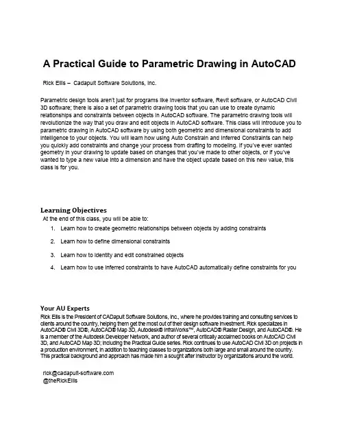
A Practical Guide to Parametric Drawing in AutoCAD Rick Ellis – Cadapult Software Solutions, Inc.Parametric design tools aren’t just for programs like Inventor software, Revit software, or AutoCAD Civil 3D software; there is also a set of parametric drawing tools that you can use to create dynamic relationships and constraints between objects in AutoCAD software. The parametric drawing tools will revolutionize the way that you draw and edit objects in AutoCAD software. This class will introduce you to parametric drawing in AutoCAD software by using both geometric and dimensional constraints to add intelligence to your objects. You will learn how using Auto Constrain and Inferred Constraints can help you quickly add constraints and change your process from drafting to modeling. If you’ve ever wanted geometry in your drawing to update based on changes that you’ve made to other objects, or if you’ve wanted to type a new value into a dimension and have the object update based on this new value, this class is for you.Learning ObjectivesAt the end of this class, you will be able to:1. Learn how to create geometric relationships between objects by adding constraints2. Learn how to define dimensional constraints3. Learn how to identity and edit constrained objects4. Learn how to use inferred constraints to have AutoCAD automatically define constraints for you Your AU ExpertsRick Ellis is the President of CADapult Software Solutions, Inc., where he provides training and consulting services to clients around the country, helping them get the most out of their design software investment. Rick specializes in AutoCAD® Civil 3D®, AutoCAD® Map 3D, Autodesk® InfraWorks™, AutoCAD® Raster Design, and AutoCAD®. He is a member of the Autodesk Developer Network, and author of several critically acclaimed books on AutoCAD Civil3D, and AutoCAD Map 3D; including the Practical Guide series. Rick continues to use AutoCAD Civil 3D on projects in a production environment, in addition to teaching classes to organizations both large and small around the country. This practical background and approach has made him a sought after instructor by organizations around the world.**************************@theRickEllisOverviewWhat is parametric drawing?The Autodesk Definition: “Feature in AutoCAD that assigns constraints to objects, establishing the distance, location, and orientation of objects with respect to other objects.”If the defini tion above didn’t answer all of your questions about parametric drawing, I’ll expand on that and go into a bit more detail. AutoCAD 2010 introduced Parametric drawing. This is not only a relatively new feature for AutoCAD, it is a new concept that will change the way that you create and edit drawings in AutoCAD. While this is a somewhat new feature for AutoCAD, similar tools for parametric design have been in other products like Inventor, Revit, and Civil 3D for some time and you may be familiar with them. Put simply, the idea of parametric drawing is that objects can be related to each other. For example, if you want two lines to be parallel, they would always be parallel. If you change one line then the other will update to match it. This is just one example. However, if you think about all the possibilities, and all the time that you have spent editing drawings to make sure that all the necessary and related changes have been made for a simple change to the design, these tools have the potential to revolutionize the way that you work.AutoCAD uses two types of Parametric Constraints:▪Geometric Constraints∙The Autodesk Definition: “Rules that define the geometric relationships of objects (or points of objects) elements and control how an object can change shape or size.Geometric constraints are coincident, collinear, concentric, equal, fix, horizontal, parallel,perpendicular, tangent, and vertical.”∙Sticky Object Snaps. They maintain the geometric relationship between objects rather than setting it once at the time you use the object snap and then allowing it to change inthe future.∙Add intelligence to your drawings.∙Allow you to think more about modeling and less about drafting.▪Dimensional Constraints∙The Autodesk Definition: “Parametric dimensions tha t control the size, angle, or position of geometry relative to the drawing or other objects. When dimensions are changed, theobject resizes.”∙You can type the value into a dimension and the object updates. It’s the opposite of associative dimensions. With Dimensional Constraints the dimension value drives thegeometry rather than the geometry driving the dimension.∙Can include equations.∙Can even reference other objects. For example, line 1 is twice the length of line 2.Exercise 1 – Working with Existing Constraints1. Open the drawing Widget Assembly complete.dwg from the folder called Completed Assemblyin the dataset.2. Select the block representing the slider on the shaft (identified by callout number 2).3. Move the block.4. Notice the block can only move along the shaft and the arm rotates as it moves.5. Double click the dimension d1 and change the value to 1.56. Notice that changing the value of the dimension moves the block.7. Select and move one of the callouts.8. Notice the entire row of callouts moves together.9. Try moving other pieces of this assembly to see the different constraints in action.10. Open the drawing Parametric - geometric.dwg from the dataset.11. Move and stretch different pieces of the orthographic projection to see how constraints have beenset up within it.Geometric ConstraintsGeometric Constraints maintain the geometric relationship between objects based on basic geometric properties of the entity or entities you apply them to. AutoCAD supports the following geometric constraint types:▪Coincident▪Co-linear▪Tangent▪Perpendicular▪Parallel▪Horizontal (relative to the current UCS X axis)▪Vertical (relative to the current UCS Y axis)▪Concentric▪Equal▪Symmetric▪Smooth▪FixedThe commands to create and manage Geometric Constraints can be found on the Parametric tab of the ribbon.The table below shows the types of objects that can be used to create geometric constraints and their constraint points.Tips when creating geometric constraints:▪When applying constraints between two entities AutoCAD modifies the second entity selected, leaving the first entity unmodified.▪If you convert an object that has constraints to a ployline the constraints are lost.▪If you explode a polyline that has constraints the constraints are lost.▪If you copy an object with constraints the constraints are copied if all the objects involved in the constraint are copied.Constraint BarsConstraint Bars provide a heads-up interface to help you manage geometric constraints in your drawings. Constraint Bars look and behave a lot like transparent floating tool bars, except that each button on a bar represents a single geometric constraint.When you place your cursor over individual constraints on a constraint bar AutoCAD highlights the button, the entity the constraint applies to, and the corresponding button and entity participating in the constraint.When you right-click on a constraint on the constraint bar there are several commands which you can perform on the constraint, including deleting the constraint, hiding the bar, or managing the constraint bar settings.To delete all constraints on an entity use the Delete Constraints command. Ribbon: Parametric tab >> Manage panel >> Delete Constraints.Exercise 2 – Working with Geometric Constraints1. Open the drawing Parametric - geometric.dwg from the dataset.2. Pan to a blank area of the drawing.3. Draw 4 individual lines similar to the graphic below.4. Add Geometric Constraints to make this a dynamic rectangle.a. Use the Coincident, Parallel, and Perpendicular constraints.5. Zoom extents to find the bracket in the drawing as displayed below.6. Add Geometric Constraints to make the bracket hinge at the corner while keeping both sides ofthe part the same size.7. Zoom extents to find the orthographic projection.8. Copy the orthographic projection.9. Remove all the constraints from the orthographic projection.10. Add geometric constraints to the orthographic projection to make it behave as the original.Auto ConstrainIf applying geometric constraints one at a times seems like a tedious task there is an option to let AutoCAD look for objects that can be constrained and add them for you. Auto Constrain examines entities you select and attempts to automatically constrain the geometry based on its current position.You can control the settings for the Auto Constrain command in the Constraint Settings dialog box. Ribbon: Parametric tab >> Geometric panel >> >> Constraint Settings.Here you can select the type(s) of constraints that you want the Auto Constrain command to apply. You can also set Tolerances for distance and angle. These tolerances will determine if constraints are applied and objects are modified when they are “close” to geometrica lly accurate. When used properly this can help clean up a drawing that was created without using object snaps. However, you want to choose your tolerances carefully as it will allow the Auto Constrain command to modify geometry. If you only want the Auto Constrain command to apply constraints where the geometry is perfect and not modify any geometry, set the tolerances to 0.Inferred ConstraintsInferred constraints automatically apply geometric constraints while creating and editing geometric objects, removing the need for you to add constraints later. The Infer Constraints mode works with your object snaps and is enabled with a toggle on the status bar.Once enabled object snaps that are used when creating or editing objects are also used to infer geometric constraints. Objects are not modified by inferred constraints.Exercise 3 – Working with Auto Constrain and Inferred Constraints1. Open the drawing Parametric – Inferred.dwg from the dataset.2. Pan to a blank area of the drawing.3. Draw a rectangle using the rectangle command.4. Use the Auto Constrain command to add constraints.5. Notice what constraints are added.6. Zoom extents to find the bracket in the drawing as displayed below.7. Use the Auto Constrain command to add constraints.8. Notice what constraints are added.9. Turn on Inferred constraints.10. Draw a rectangle using the rectangle command.11. Notice what constraints are added.Dimensional ConstraintsDimensional Constraints constrain objects by allowing you to enter values or formulas. They work similar to associative dimensions, just in reverse. While associative dimensions update the value of the dimension as the object changes, dimensional constraints update the object when the value of the dimension changes. The dimensions drive the geometry rather than the geometry driving the dimensions. Dimensional constraints come in the following types:▪Aligned▪Horizontal▪Vertical▪Radial▪Diameter▪AngularDimensional constraints can constrain the following properties:▪Distances between objects, or between points on objects▪Angles between objects, or between points on objects▪Sizes of arcs and circlesThere two different kinds of dimensional constraints:▪Dynamic∙Maintain the same size regardless of zoom level∙Can easily be turned on or off globally in the drawing∙Display using a fixed, predefined dimension style∙Position the textual information automatically, and provide triangle grips with which you can change the value of a dimensional constraint∙Do not display when the drawing is plotted▪Annotational∙Change their size when zooming in or out∙Display individually with layers∙Display using the current dimension style∙Provide grip capabilities that are similar to those on dimensions∙Display when the drawing is plottedIf you need to control the dimension style of dynamic constraints, or if you need to plot dimensional constraints, use the Properties palette to change dynamic constraints to annotational constraints.The commands to create and manage Dimensional Constraints can be found on the Parametric tab of the ribbon.Tips when creating dimensional constraints:▪When applying dimensional constraints AutoCAD modifies the constrained geometry to satisfy the new constraint.▪If you convert an object that has constraints to a ployline the constraints are lost.▪If you explode a polyline that has constraints the constraints are lost.▪If you copy an object with dimensional constraints the constraints are copied.▪Dimensional constraints can contain equations.The example above contains a rectangle with two basic dimensional constraints.The example above contains a rectangle with two dimensional constraints where the length (d1) is equal to twice the height (d2).You can manage all the values of your dimensional constraints with the Parameters Manager. Ribbon: Parametric tab >> Manage panel >> Parameters Manager.In the Parameters Manager you can edit expressions and even add user defined variables that you can use in expressions.Exercise 4 – Working with Dimensional Constraints1. Open the drawing Parametric - dimensions.dwg from the dataset.2. Zoom to the rectangle.a. It already has geometric constraints.3. Add Dimensional Constraints for the width and length.4. Edit the width to be 3.5. Edit the length to be twice the width by editing the expression.6. Zoom extents to find the bracket in the drawing as displayed below.a. It already has geometric constraints.7. Add a dimensional constraint to control the angle.8. Draw circles at each end of the part.9. Use a concentric geometric constraint to position them10. Add a dimensional constraint that makes them half the outer radius of the part.Constraints in Dynamic BlocksIntroduced in AutoCAD 2005, Dynamic Blocks extend the capabilities of traditional blocks by providing the ability to define custom grips and properties for your blocks which affect the geometry for the block. You create dynamic blocks by combining Block Actions and Block Action Parameters within the block definition. Now you can extend the power of blocks even further by adding geometric and dimensional constraints to your dynamic blocks.When you add geometric and dimensional constraints to dynamic blocks it is best to add them in the block editor using the commands on the Block Editor tab of the Ribbon.A Block Properties table allows you to define and control values for parameters and properties within a block definition. This will become the list of selectable values in the dynamic block.Exercise 5 – Working Constraints in Dynamic Blocks1. Open the drawing Parametric - blocks.dwg from the dataset.2. Open the block editor.a. Ribbon: Insert tab >> Block panel >> Block Editor.b. Name the new block AUParametric.3. Draw a rectangle using the rectangle command starting the lower left corner of the rectangle at0,0.4. Add Geometric Constraints to make this a dynamic rectangle.5. Add Dimensional Constraints for the width and length.6. Edit the width to be 5.7. Edit the length to be twice the width by editing the expression.8. Add a Block Table.a. Place the block table near the origin of the block.b. Placement of the block table does not need to be exact. It will be the location of a grip onthe block that can be used to select standard sizes.9. Enter 1 for the number of grips.10. Click the Add Properties button11. Select the d1 parameter and Click <<OK>>.12. Enter values for d1 as shown above.13. Click <<OK>> when finished.14. Close the block editor and save the changes.15. Insert the block anywhere in your drawing.16. Select the block and notice the available grips.a. You will be able to stretch it in the vertical direction and the rectangle will keep the 2:1ratio of length to width.b. Select the block table grip and you will see the predefined widths.c. Select one of the values and notice how the block resizes.ConclusionParametric drawing in AutoCAD with geometric and dimensional constraints is a powerful set of tools that may drastically change the way that you create and edit drawings. I hope that this introduction to these exciting features has got you thinking about ways that you can apply it to your own drawings and projects.I encourage you to try it out, start small at first, but I am confident that you fill not only find these tools a powerful time saver but also intuitive and easy to learn.。
CAD文件中的形生成和参数化设计技巧CAD文件是计算机辅助设计的缩写,是一种广泛应用于工程和制造领域的设计工具。
在CAD软件中,形生成和参数化设计技巧是非常重要的,能够提高设计效率和准确性。
本文将介绍CAD文件中的形生成和参数化设计技巧,帮助读者更好地应用CAD软件进行设计。
一、形生成技巧形生成是指通过CAD软件绘图工具创建几何形状的过程。
在CAD软件中,有许多形生成工具和命令可以使用,下面将介绍几种常用的形生成技巧。
1. 直线和曲线生成在CAD软件中,使用线段工具可以创建直线,通过指定起点和终点的坐标来确定直线的位置和方向。
而曲线的生成则需要使用曲线工具,如圆弧工具、样条曲线工具等。
在生成曲线时,可以通过指定曲率、半径等参数来控制曲线的形状。
2. 多边形生成多边形是由若干条线段连接而成的几何形状。
在CAD软件中,可以使用多边形工具来绘制正多边形、不规则多边形等。
绘制多边形时,可以通过指定边长或角度来确定多边形的大小和形状。
3. 实体生成在CAD软件中,可以使用实体生成工具来创建立方体、圆柱体、球体等实体几何形状。
通过指定尺寸和位置参数,可以快速生成所需的实体。
二、参数化设计技巧参数化设计是指使用参数来定义设计要素和变量,通过改变参数的值,实现对设计进行修改和优化。
在CAD软件中,参数化设计技巧可以大大提高设计的灵活性和可持续性。
1. 参数定义在CAD软件中,可以通过参数管理工具来定义参数。
参数可以是尺寸、角度、位置等设计要素的数值表示。
通过定义参数,可以将设计中的一些常用数值提取出来,方便后续的修改和调整。
2. 关联关系在CAD软件中,可以通过关联关系工具将设计要素和参数进行关联。
通过建立关联关系,当参数发生改变时,与之相关的设计要素也会自动更新。
这样可以实现快速修改设计的目的,节省大量的时间和精力。
3. 参数化建模参数化建模是使用参数化设计技巧进行三维建模的一种方法。
在CAD软件中,可以通过定义参数来控制建模的尺寸、形状等。
利用CAD进行参数化建模的技巧在现代设计领域中,CAD (Computer-Aided Design) 软件已成为设计师们最常使用的工具之一。
然而,许多人可能对如何利用CAD实现参数化建模感到困惑。
本文将为您介绍一些利用CAD软件进行参数化建模的技巧。
首先,什么是参数化建模?参数化建模是指利用可调整的参数来创建和修改模型,从而简化设计和提高效率。
利用参数可以在设计中快速调整尺寸、形状和其他属性,而无需重新绘制整个模型。
这种建模方法非常适用于需要频繁修改和调整设计的项目。
在CAD软件中,有许多工具可以帮助我们实现参数化建模。
其中之一是“参数表”功能。
参数表允许您在模型中定义和更改参数,然后根据需要调整这些参数。
通过使用参数表,您可以逐一更改模型的各个参数,而无需手动修改每个单独的元素。
例如,假设您正在设计一个硬件零件的三维模型。
您可以使用参数表来定义零件的尺寸、孔距、角度等参数。
一旦定义了这些参数,您就可以通过修改参数表中的数值来快速调整整个模型。
这个功能在产品生命周期的不同阶段,如设计、制造和维护中,都非常有用。
除了参数表外,CAD软件还常常提供一些几何约束工具。
几何约束是一种将不同几何元素关联起来的方法,以保持它们之间的相对位置和关系。
通过使用几何约束,我们可以创建一个可自动调整形状的模型。
举个例子,假设您正在设计一个可折叠的夹子。
您可以使用CAD软件中的约束工具将夹子的各个部分约束在一起。
例如,您可以将夹子的两个臂约束为等长,这样无论您如何调整夹子的大小,它们始终保持相等。
此外,您还可以添加角度和对称性约束,以确保夹子在不同位置都能正确运作。
除了参数表和几何约束,CAD软件还常常提供“公式编辑器” 功能。
通过使用公式编辑器,您可以在模型中使用数学公式来定义参数和约束。
这使得您可以更灵活地控制模型的属性和形状。
公式编辑器对于复杂模型和依赖于其他参数的参数化设计非常有用。
最后,还有一个技巧需要注意:当您在进行参数化建模时,务必保持模型的良好结构和层次结构。
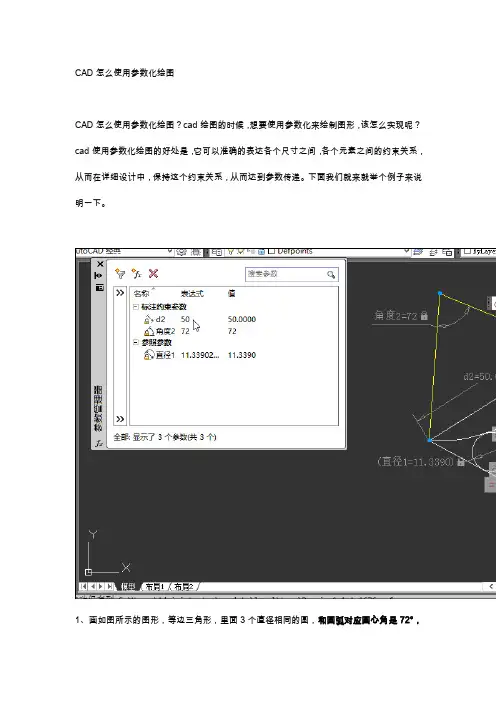
CAD怎么使用参数化绘图
CAD怎么使用参数化绘图?cad绘图的时候,想要使用参数化来绘制图形,该怎么实现呢?cad使用参数化绘图的好处是,它可以准确的表达各个尺寸之间,各个元素之间的约束关系,从而在详细设计中,保持这个约束关系,从而达到参数传递。
下面我们就来就举个例子来说明一下。
1、画如图所示的图形,等边三角形,里面3个直径相同的圆,和圆弧对应圆心角是72°,
他们之间都是相切关系。
尺寸如图,求圆的直径。
2、如果不用参数化,用几何画法,那个需要有丰富几何知识,才能画的出来。
现在用参数化约束他们之间关系,约束标注即可解出。
画任意形状三角形。
3、画如图圆弧
4、画任意三个圆
5、画2条辅助线,调出工具栏
6、快速约束重合关系
7、设定一个参考点
8、约束相等关系
9、约束相切关系
10、约束标注长度
11、约束标注角度
12、修改标注尺寸
13、测量小圆直径
14、从上面画图过程可以清楚的描述他们的关系,可以通过修改尺寸值达到不同的小圆直径,这就参数化的过程,输入值后,我们不关心过程,只要最后的结果,这样,直观快速的得出想要的结果。
以上就是cad参数化绘图的教程,希望大家喜欢
推荐阅读:
CAD制图初学入门/
模具CAD /product/mujucad/ CAD填充/
CAD面积命令/
CAD命令大全/。
CAD绘图中的参数化设计和快速建模技巧在现代工程设计领域,CAD软件的广泛应用已成为不可忽视的趋势。
通过CAD软件,工程师们能够更快速、更准确地进行设计,并实现灵活的参数化设计。
本文将介绍CAD绘图中的参数化设计和快速建模技巧,帮助你更高效地应用CAD软件。
首先,我们来了解一下参数化设计的概念。
参数化设计是指通过对图形进行参数设定,实现模型的调整和变形。
通过设置基本形状的参数,可以快速生成符合需求的模型。
常见的CAD软件如AutoCAD和SolidWorks都支持参数化设计功能。
在进行参数化设计时,我们可以使用CAD软件提供的多种参数类型,如长度、宽度、高度、角度等。
通过设置参数的数值,我们可以实现对模型的灵活控制。
例如,对于一个盒子的设计,我们可以设定长度和宽度的参数,然后根据具体需求进行调整,从而实现盒子尺寸的灵活变化。
在使用CAD软件进行参数化设计时,还可以设置关联性。
通过设置各个参数之间的关联关系,可以实现模型的自动更新。
例如,我们在设计一个零件时,可以设置长度和宽度的参数,并通过公式将它们关联起来。
当我们修改其中一个参数时,另一个参数会自动更新,从而实现模型的快速调整。
除了参数化设计,快速建模也是CAD软件中的重要功能。
通过快速建模技巧,我们可以更高效地创建复杂的模型。
以下是几种常用的快速建模技巧:1. 使用图纸参考:在建模过程中,可以先创建一个图纸作为参考。
我们可以根据图纸上的尺寸和形状,在CAD软件中创建相应的基本形状,并通过连线和曲线工具连接它们,最终生成需要的模型。
2. 使用草图和命令:CAD软件中常常提供了各种草图和命令工具,可以快速创建复杂的形状。
通过掌握这些工具的使用,我们可以在短时间内绘制出具有复杂曲线和形状的模型。
3. 使用模型复制和对称功能:当需要创建多个相似的模型时,我们可以使用CAD软件的复制和对称功能。
通过复制和对称已有模型,可以快速生成需要的数量,并保持它们之间的对称性。
使用CAD进行参数化建模的步骤CAD是计算机辅助设计的缩写,是一种应用软件,主要用于制图和设计方面。
它在建筑、机械、电子等各个领域都有广泛的应用。
参数化建模是CAD设计中的一项重要技术,它可以帮助设计师快速高效地创建复杂的模型,并且可以方便地进行修改和调整。
下面将介绍使用CAD进行参数化建模的步骤。
第一步:设置参数在进行参数化建模之前,我们需要先设置一些参数。
这些参数可以是各种尺寸、角度和位置等。
通过设置参数,我们可以方便地调整模型的大小和形状,提高设计的灵活性。
比如,在进行一个矩形模型的建模时,我们可以设置矩形的长和宽作为参数。
这样,在后续的操作中,我们就可以根据需要随时调整矩形的大小。
第二步:绘制基本图形在进行参数化建模之前,我们需要先绘制一些基本图形。
这些图形可以是线段、圆、矩形等。
通过这些基本图形,我们可以构建出更加复杂的模型。
在CAD软件中,我们可以使用各种绘图工具来绘制基本图形。
比如,在绘制一个矩形时,我们可以通过选择两个对角线上的点来确定矩形的位置和大小。
第三步:应用约束一旦绘制了基本图形,我们就可以开始应用约束。
约束是限制图形的几何关系,可以使得图形保持特定的形状或位置。
在CAD软件中,我们可以通过不同的约束工具来将图形进行约束。
比如,我们可以将一个矩形的四个角都设置成直角,或者将一个线段的长度固定。
通过应用约束,我们可以使得建模过程更加准确和可控,减少错误和误差。
第四步:创建参数表在应用约束之后,我们就可以开始创建参数表。
参数表是一个包含各种参数的列表,可以帮助我们方便地管理和修改参数。
在CAD软件中,我们可以使用参数表工具来创建参数表。
通过参数表,我们可以查看和修改各个参数的值,从而调整模型的大小和形状。
第五步:进行参数化建模经过以上的准备工作,我们就可以开始进行参数化建模了。
在CAD软件中,我们可以使用各种建模工具来进行参数化建模。
比如,在进行一个箱子的建模时,我们可以通过设置长度、宽度和高度等参数来控制箱子的大小。
CAD二维图形参数化设计教程CAD是一种常用的计算机辅助设计软件,它可以帮助工程师和设计师在二维平面中创建精确和复杂的图形。
参数化设计是其中一项强大的功能,它允许用户定义和修改图形的参数,从而实现设计的灵活性和可重复性。
本教程将为您介绍如何在CAD中利用参数化设计创建二维图形。
首先,打开CAD软件并选择“新建”文件。
然后,选择“绘图”选项,选择适当的图层和单位设置。
您可以根据需要选择英寸、毫米或其他单位。
接下来,我们将通过示例来演示如何创建参数化的正方形。
在图形绘制工具栏中,选择“矩形”工具,并在工作区中绘制一个矩形。
您可以使用鼠标点击和拖动操作来绘制矩形的边界。
在CAD的命令行中,输入“D”并按回车键,该命令将打开维度设置。
在这里,您可以定义矩形的参数,如边长、宽度、高度等。
输入合适的数值,并按回车键确认。
现在,您可以通过更改参数值来修改矩形的大小。
在CAD的命令行中输入“M”并按回车键,该命令将打开修改命令。
选择要修改的矩形,并输入新的参数值。
CAD将自动更新图形以反映新的尺寸。
除了矩形,CAD还支持创建其他几何图形,如圆、椭圆和多边形。
您可以按照相似的步骤来创建和修改这些图形的参数。
记住,参数化设计的主要优势在于可以快速和灵活地进行设计更改。
除了基本的参数化设计,CAD还提供了高级功能来进一步增强设计的灵活性。
例如,您可以创建变量并使用它们在多个图形之间共享数值。
这样,当您修改变量的值时,所有关联的图形都会自动更新。
要创建变量,请在CAD的命令行中输入“V”并按回车键,该命令将打开变量设置。
在这里,您可以定义变量的名称和初始数值。
一旦创建了变量,您可以在其他命令中使用它。
例如,输入“@变量名称”可以在图形维度设置中引用该变量。
在CAD中,您还可以使用表达式来进一步控制图形的参数化。
表达式可以包含数学运算、函数和逻辑运算符等内容。
例如,您可以使用表达式来计算矩形的面积或周长。
要使用表达式,请在CAD的命令行中输入“E”并按回车键,该命令将打开表达式设置。
如何在CAD中进行参数化设计在CAD软件中进行参数化设计是一项非常重要的技能,它可以帮助设计师更加高效地创建和修改模型。
参数化设计是指利用变量和公式来定义实体的特征和关系,从而使得模型能够根据不同的参数值实时调整。
首先,我们需要明确参数化设计的目的和优势。
参数化设计的最大优势在于可以快速修改和调整模型。
通过定义参数,我们可以灵活地改变模型的尺寸、形状、比例等特征,而无需手动重新绘制。
为了进行参数化设计,我们需要在CAD软件中学习一些基本技巧和方法。
首先,我们需要了解如何定义参数。
在大多数CAD软件中,我们可以使用变量或公式来代表模型的尺寸和特征。
例如,我们可以定义一个长度参数L,并将其值设定为10单位。
这样,在后续设计中,我们只需修改L的值,就能够自动改变模型的长度。
另一个重要的技巧是如何在模型中使用参数。
在CAD软件中,我们可以通过数值输入或函数输入等方式,将参数应用于不同的图形对象。
例如,我们可以通过选择一个线段,然后输入“L/2”作为线段的长度,这样线段的长度会自动根据参数L的值而变化。
在进行参数化设计时,我们还需要注意一些细节。
首先,我们需要合理命名和组织参数。
一个好的命名规范可以帮助我们更加方便地识别和理解参数的用途和意义。
另外,我们还需要注意参数之间的关联性。
不同参数之间可能存在一定的依赖关系,需要确保参数的定义和使用是正确和一致的。
在CAD软件中,还有一些高级的参数化设计工具和功能可以帮助我们更好地进行设计。
例如,有些CAD软件提供了参数表和参数管理器等功能,可以集中管理和编辑参数。
另外,一些CAD软件还提供了参数驱动模块和宏命令等功能,可以进一步扩展和增强参数化设计的能力。
在实际应用中,参数化设计可以广泛用于各种领域和项目。
无论是建筑设计、机械设计还是产品设计,参数化设计都可以帮助我们提高设计效率、减少错误和改动的成本。
总而言之,在CAD软件中进行参数化设计是一项必备的技能。
通过合理地定义和使用参数,我们可以更加灵活地创建和修改模型,并且提高设计效率和质量。
CAD参数化建模教程CAD(计算机辅助设计)是一种常用于工程领域的软件,它可以帮助我们更方便地进行设计和建模。
而参数化建模技术则是CAD中非常重要的一项功能,它可以帮助我们快速地创建复杂的模型,并且可以轻松地修改和调整模型的参数。
在本文中,我们将介绍CAD参数化建模的一些基本操作和使用技巧,帮助读者更好地掌握这项技术。
首先,我们需要了解CAD中的参数化建模是如何工作的。
在CAD 软件中,我们可以为模型的各个部分添加各种参数,如长度、角度、半径等。
这些参数可以用于控制模型的尺寸和形状,并且可以是可调整的。
通过修改这些参数,我们可以快速地调整模型的尺寸和形状,而无需重新绘制整个模型。
接下来,让我们来看一下CAD参数化建模的具体操作。
在CAD软件中,我们通常可以使用“参数”或“变量”命令来添加参数。
例如,我们可以使用“长度”命令来添加一个长度参数,然后通过指定具体的数值来设定参数的值。
一旦参数被添加,我们可以在模型的不同部分使用这个参数来控制其尺寸。
例如,我们可以使用长度参数来控制一个矩形的边长,使其灵活地调整长度。
在CAD参数化建模中,我们还可以使用一些函数和表达式来创建更复杂的参数。
例如,我们可以使用三角函数来创建角度参数,然后使用这个参数来控制模型的旋转。
此外,我们还可以使用表达式来计算和控制多个参数之间的关系。
这些功能使得CAD参数化建模在处理复杂的几何形状和设计问题时更加灵活和高效。
需要注意的是,在CAD参数化建模中,我们需要遵循一些设计原则来确保模型的正确性和可靠性。
首先,我们需要选择合适的参数名称和单位,以便更好地理解和操作模型。
其次,我们需要仔细检查参数之间的关系,确保它们在任何情况下都能提供正确的结果。
最后,我们需要对模型进行严格的测试和验证,以确保它在各种情况下都能正常运行。
除了基本的操作和设计原则,CAD参数化建模中还有一些高级的技巧和功能。
例如,我们可以使用“约束”命令来添加几何约束,以确保模型在变量改变时仍然保持一致。
《AutoCAD机械制图教程》教案
图8-1平面图形
15分钟三、相关知识讲解
1.几何约束
2.标注约束
3.推断约束
4.约束设置
5.参数化绘图的一般步骤
演示法
讲授法
25分钟四、任务实施
第1步:设定绘图区域大小为800mm×800mm,并使该区域充满显
示于整个图形窗口。
第2步:打开极轴追踪、对象捕捉及自动追踪功能,设定对象捕捉
方式为“端点”、“交点”及“圆心”。
第3步:绘制图形,图形尺寸任意,如图8-2(a)所示。
修剪并
倒圆角形成外轮廓草图,如图8-2(b)所示。
(a)(b)
图8-2 绘制外轮廓草图
第4步:启动自动添加几何约束功能,给所有图形对象添加几何约
束,如图8-3所示。
演示法
讲练结合法
图8-3自动添加几何约束
第5步:给圆弧A、B、C添加相等约束,使3个圆弧的半径相等;对左下角点添加固定约束,如图8-4(a)所示。
给圆心D、F及圆弧中点E添加水平约束,使三点位于同一条水平线上,如图8-4(b)所示。
操作时,可利用点命令和对象捕捉确定要约束的目标点。
(a)(b)
图8-4 创建约束
第6步:单击〖参数化〗工具栏上的“”按钮,隐藏几何约束,并添加半径约束、角度约束、水平约束、竖直约束,如图8-5所示。
将角度值修改为60°,结果如图8-6所示。
图8-5 添加标注约束图8-6 修改角度约束
第7步:绘制圆及线段,如图8-7所示。
修剪多余线条并自动添加几何约束,如图8-8所示。
图8-7 图8-8
第8步:给圆弧G、H添加同心约束;给线段I、J添加平行约束等,如图8-9所示。
图8-9图8-10
第9步:复制线框,如图8-10所示。
对新线框添加同心约束,如图8-11所示。
第10步:使圆弧L、M的圆心位于同一条水平线上,并让它们的半径相等,如图8-12所示。
图8-11 图8-12
第11步:添加半径约束,使圆弧的半径尺寸为40,如图8-13所示。
将半径值由40改为30,结果如图8-14所示。
图8-13 图8-14
第12步:修改标注约束名称的格式。
在【约束设置】对话框的{标注}选项卡中,“标注名称格式”下拉列表中选择“值”选项,再取消对“为注释性约束显示锁定图标”选项的选择,绘制中心线,结果如图8-1所示。
第13步:保存图形。
20分钟五、模仿练习
练习法现场指导法
10分钟
六、分层教学与举一反三
图8-15
练习法
5分钟七、评价考核
根据学生完成任务及练习的质量与数量进行评价。
记分评价法
5分钟八、课堂小结
重点小结【约束设置】对话框的使用方法,几何约束和标注
约束的添加与编辑方法。
九、作业布置
完成下面技能训练与检测并预习任务9的相关知识。
1. 利用AutoCAD的参数化功能绘制平面图形,如图8-16所
示。
先画出图形的大致形状,然后给所有对象添加几何约束及标注
约束,使图形处于完全约束状态。
修改其中部分尺寸使图形变形,
结果如图8-17所示。
讲解法
图8-15 图8-16
2. 利用AutoCAD的参数化功能绘制平面图形,如图8-17至
图8-18所示。
先画出图形的大致形状,然后给所有对象添加几何
约束及标注约束,使图形处于完全约束状态。
图8-17
图8-18
教研室主任签名累计课时 2。