Hydraulic Slave Cylinders & Wheel Cylinders Product Guide
- 格式:pdf
- 大小:154.09 KB
- 文档页数:8

中英文对照资料外文翻译文献Automobile Brake SystemThe braking system is the most important system in cars. If the brakes fail, the result can be disastrous. Brakes are actually energy conversion devices, which convert the kinetic energy (momentum) of the vehicle into thermal energy (heat).When stepping on the brakes, the driver commands a stopping force ten times as powerful as the force that puts the car in motion. The braking system can exert thousands of pounds of pressure on each of the four brakes.Two complete independent braking systems are used on the car. They are the service brake and the parking brake.The service brake acts to slow, stop, or hold the vehicle during normal driving. They are foot-operated by the driver depressing and releasing the brake pedal. The primary purpose of the brake is to hold the vehicle stationary while it is unattended. The parking brake is mechanically operated by when a separate parking brake foot pedal or hand lever is set.The brake system is composed of the following basic components: the “master cylinder” which is located under the hood, and is directly connected tothe brake pedal, converts driver foot’s mechanical pressure into hydraulic pressure. Steel “brake lines” and flexible “brake hoses” connect the master cylin der to the “slave cylinders” located at each wheel. Brake fluid, specially designed to work in extreme conditions, fills the system. “Shoes” and “pads” are pushed by the slave cylinders to contact the “drums” and “rotors” thus causing drag, which (hopefully) slows the car.The typical brake system consists of disk brakes in front and either disk or drum brakes in the rear connected by a system of tubes and hoses that link the brake at each wheel to the master cylinder (Figure).Basically, all car brakes are friction brakes. When the driver applies the brake, the control device forces brake shoes, or pads, against the rotating brake drum or disks at wheel. Friction between the shoes or pads and the drums or disks then slows or stops the wheel so that the car is braked.In most modern brake systems (see Figure 15.1), there is a fluid-filled cylinder, called master cylinder, which contains two separate sections, there is a piston in each section and both pistons are connected to a brake pedal in the driver’s com partment. When the brake is pushed down, brake fluid is sent from the master cylinder to the wheels.At the wheels, the fluid pushes shoes, or pads, against revolving drums or disks. The friction between the stationary shoes, or pads, and the revolving drums or disks slows and stops them. This slows or stops the revolving wheels, which, in turn, slow or stop the car.The brake fluid reservoir is on top of the master cylinder. Most cars today have a transparent r reservoir so that you can see the level without opening the cover. The brake fluid level will drop slightly as the brake pads wear. This is a normal condition and no cause for concern. If the level drops noticeably over ashort period of time or goes down to about two thirds full, have your brakes checked as soon as possible. Keep the reservoir covered except for the amount of time you need to fill it and never leave a cam of brake fluid uncovered. Brake fluid must maintain a very high boiling point. Exposure to air will cause the fluid to absorb moisture which will lower that boiling point.The brake fluid travels from the master cylinder to the wheels through a series of steel tubes and reinforced rubber hoses. Rubber hoses are only used in places that require flexibility, such as at the front wheels, which move up and down as well as steer. The rest of the system uses non-corrosive seamless steel tubing with special fittings at all attachment points. If a steel line requires a repair, the best procedure is to replace the compete line. If this is not practical, a line can be repaired using special splice fittings that are made for brake system repair. Y ou must never use copper tubing to repair a brake system. They are dangerous and illegal.Drum brakes, it consists of the brake drum, an expander, pull back springs, a stationary back plate, two shoes with friction linings, and anchor pins. The stationary back plate is secured to the flange of the axle housing or to the steering knuckle. The brake drum is mounted on the wheel hub. There is aclearance between the inner surface of the drum and the shoe lining. To apply brakes, the driver pushes pedal, the expander expands the shoes and presses them to the drum. Friction between the brake drum and the friction linings brakes the wheels and the vehicle stops. To release brakes, the driver release the pedal, the pull back spring retracts the shoes thus permitting free rotation of the wheels.Disk brakes, it has a metal disk instead of a drum. A flat shoe, or disk-brake pad, is located on each side of the disk. The shoes squeeze the rotatin g disk to stop the car. Fluid from the master cylinder forces the pistons to move in, toward the disk. This action pushes the friction pads tightly against the disk. The friction between the shoes and disk slows and stops it. This provides the braking action. Pistons are made of either plastic or metal. There are three general types of disk brakes. They are the floating-caliper type, the fixed-caliper type, and the sliding-caliper type. Floating-caliper and sliding-caliper disk brakes use a single piston. Fixed-caliper disk brakes have either two or four pistons.The brake system assemblies are actuated by mechanical, hydraulic or pneumatic devices. The mechanical leverage is used in the parking brakes fitted in all automobile. When the brake pedal is depressed, the rod pushes the piston of brake master cylinder which presses the fluid. The fluid flows through the pipelines to the power brake unit and then to the wheel cylinder. The fluid pressure expands the cylinder pistons thus pressing the shoes to the drum or disk. If the pedal is released, the piston returns to the initialposition, the pull backsprings retract the shoes, the fluid is forced back to the master cylinder and braking ceases.The primary purpose of the parking brake is to hold the vehicle stationary while it is unattended. The parking brake is mechanically operated by the driver when a separate parking braking hand lever is set. The hand brake is normally used when the car has already stopped. A lever is pulled and the rear brakes are approached and locked in the “on” position. The car may now be left without fear of its rolling away. When the driver wants to move the car again, he must press a button before the lever can be released. The hand brake must also be able to stop the car in the event of the foot brake failing. For this reason, it is separate from the foot brake uses cable or rods instead of the hydraulic system.Anti-lock Brake SystemAnti-lock brake systems make braking safer and more convenient, Anti-lock brake systems modulate brake system hydraulic pressure to prevent the brakes from locking and the tires from skidding on slippery pavement or during a panic stop.Anti-lock brake systems have been used on aircraft for years, and some domestic car were offered with an early form of anti-lock braking in late 1990’s. Recently, several automakers have introduced more sophisticated anti-lock system. Investigations in Europe, where anti-lock brakin g systems have been available for a decade, have led one manufacture to state that the number of traffic accidents could be reduced by seven and a half percent if all cars hadanti-lock brakes. So some sources predict that all cars will offer anti-lock brakes to improve the safety of the car.Anti-lock systems modulate brake application force several times per second to hold the tires at a controlled amount of slip; all systems accomplish this in basically the same way. One or more speed sensors generate alternating current signal whose frequency increases with the wheel rotational speed. An electronic control unit continuously monitors these signals and if the frequency of a signal drops too rapidly indicating that a wheel is about to lock, the control unit instructs a modulating device to reduce hydraulic pressure to the brake at the affected wheel. When sensor signals indicate the wheel is again rotating normally, the control unit allows increased hydraulic pressure to the brake. This release-apply cycle occurs several time per second to “pump” the brakes like a driver might but at a much faster rate.In addition to their basic operation, anti-lock systems have two other things in common. First, they do not operate until the brakes are applied with enough force to lock or nearly lock a wheel. At all other times, the system stands ready to function but does not interfere with normal braking. Second, if the anti-lock system fail in any way, the brakes continue to operate without anti-lock capability. A warning light on the instrument panel alerts the driver when a problem exists in the anti-lock system.The current Bosch component Anti-lock Braking System (ABSⅡ), is a second generation design wildly used by European automakers such as BWM,Mercedes-Benz and Porsche. ABSⅡsystem consists of : four wheel speed sensor, electronic control unit and modulator assembly.A speed sensor is fitted at each wheel sends signals about wheel rotation to control unit. Each speed sensor consists of a sensor unit and a gear wheel. The front sensor mounts to the steering knuckle and its gear wheel is pressed onto the stub axle that rotates with the wheel. The rear sensor mounts the rear suspension member and its gear wheel is pressed onto the axle. The sensor itself is a winding with a magnetic core. The core creates a magnetic field around the winding, and as the teeth of the gear wheel move through this field, an alternating current is induced in the winding. The control unit monitors the rate o change in this frequency to determine impending brake lockup.The cont rol unit’s function can be divided into three parts: signal processing, logic and safety circuitry. The signal processing section is the converter that receives the alternating current signals form the speed sensors and converts them into digital form for the logic section. The logic section then analyzes the digitized signals to calculate any brake pressure changes needed. If impending lockup is sensed, the logic section sends commands to the modulator assembly. Modulator assemblyThe hydraulic modulator assembly regulates pressure to the wheel brakes when it receives commands from the control utuit. The modulator assembly can maintain or reduce pressure over the level it receives from the master cylinder, it also can never apply the brakes by itself. The modulator assembly consists ofthree high-speed electric solenoid valves, two fluid reservoirs and a turn delivery pump equipped with inlet and outlet check valves. The modulator electrical connector and controlling relays are concealed under a plastic cover of the assembly.Each front wheel is served by electric solenoid valve modulated independently by the control unit. The rear brakes are served by a single solenoid valve and modulated together using the select-low principle. During anti-braking system operation, the control unit cycles the solenoid valves to either hold or release pressure the brake lines. When pressure is released from the brake lines during anti-braking operation, it is routed to a fluid reservoir. There is one reservoir for the front brake circuit. The reservoirs are low-pressure accumulators that store fluid under slight spring pressure until the return delivery pump can return the fluid through the brake lines to the master cylinder.汽车制动系统制动系统是汽车中最重要的系统。

外文原文Automobile chassisChassis include the clutch , the transmission, the drive shaft, the final drive assembly, the front suspension, the rear suspension, the steering system ,the brake system, the wheels and tires.1.ClutchThe engine produces the power to drive the vehicle . The drive line or drive train transfer the power of the engine to the wheels . The drive train consists of the parts from the back of the flywheel to the wheels . These parts include the clutch , the transmission ,the drive shaft ,and the final drive assembly .The clutch which includes the flywheel ,clutch disc , pressure plate , springs , pressure plate cover and the linkage necessary to operate the clutch is a rotating mechanism between the engine and the transmission . It operates through friction which comes from contact between the parts . That is the reason why the clutch is called a friction mechanism . After engagement, the clutch must continue to transmit all engine torque to transmission depending on the friction without slippage . The clutch is also used to disengage the engine from the drive train whenever the gears in the transmission are being shifted from gear ratio to another .To start the engine or shift the gears , the driver has to depress the clutch pedal with the purpose of disengagement the transmission from the engine . At that time , the driven members connected to the transmission input shaft are either stationary or rotating at a speed that is slower of faster than the driving members connected to engine crankshaft . There is no spring pressure on the clutch assembly parts . So there is no friction between the driving members and driven members . As the driver lets loose the clutch pedal , spring pressure increase on the clutch parts . Friction between the parts also increases . The pressure exerted by the springs on the driven members is controlled by the driver through the clutch pedal and linkage . The positive engagement of the driving and driven members is made possible the friction between the surfaces of the members . When full spring pressure is applied , the speed of the driving and driven members should be the same . At the moment , the clutch must act as a coupling device and transmit all engine power to the transmission , without slipping .However , the transmission should be engaged to the engine gradually in order to operate the car smoothly and minimize torsional shock on the drive train because an engine at idle just develop little power . Otherwise , the driving members are connected with the driven members too quickly and the engine would be stalled .The flywheel is a major part of the clutch . The flywheel mounts to the engine’s crankshaft and transmits engine torque to the clutch assembly . The flywheel , when coupled with the clutch disc and pressure plate makes and breaks the flow of power the engine to the transmission .The flywheel provides a mounting location for the clutch assembly as well . When the clutch is applied , the flywheel transfers engine torque to the clutch disc . Because of its weight , the flywheel helps to smooth engine operation . The flywheel also has a large ring gear at its outer edge , which engages with a pinion gear on the starter motor during engine cranking .The clutch disc fits between the flywheel and the pressure plate . The clutch disc has a splined hub that fits over splines on the transmission input shaft . A splined hub has grooves that match splines on the shaft . These splines fit in the grooves . Thus , the two parts held together . However , back – and – forth movement of the disc on the shaft is possible . Attached to the input shaft , the disc turns at the speed of the shaft .The clutch pressure plate is generally made of cast iron . It is round and about the same diameter as the clutch disc . One side of the pressure plate is machined smooth . This side will press the clutch disc facing are against the flywheel . The outer side has shapes to facilitate attachment of spring and release mechanism . The two primary types of pressure plate assemblies are coil spring assembly and diaphragm spring .Diaphragm spring pressure plate assemblies are widely used in most modern cars . The diaphragm spring is a single thin sheet of metal which yields when pressure is applied to it . When pressure is removed the metal spring back to its original shape . The center portion of the diaphragm spring is slit into numerous fingers that act as release levers . When the clutch assembly rotates with the engine these weights are flung outwards by centrifugal plate and cause the levers to press against the pressure plate . During disengagement of the clutch the fingers are moved forward by the release bearing . The spring pivots over the fulcrum ring and its outer rim moves away from the flywheel . The retracting spring pulls the pressure plate away from the clutch plate thus disengaging the clutch .When engaged the release bearing and the fingers of the diaphragm spring move towards the transmission . As the diaphragm pivots over the pivot ring its outer rim forces the pressure plate against the clutch disc so that the clutch plate is engaged to flywheel .The advantages of a diaphragm type pressure plate assembly are its compactness , lower weight , fewer moving parts , less effort to engage , reduces rotational imbalance by providing a balanced force around the pressure plate and less chances of clutch slippage .2. Automatic transmissionThe modern automatic transmission is by far , the most complicated mechanical component in today’s aut omobile . It is a type of transmission that sifts itself . A fluid coupling or torque converter is used instead of a manually operated clutch to connect the transmission to the engine .There are two basic types of automatic transmission based on whether the vehicle is rear wheel drive or front wheel drive . On a rear wheel drive car , the transmission is usually mounted to the back of the engine and is located under the hump in the center of the floorboard alongside the gas pedal position . A drive shaft connects the transmission to the final drive which is located in the rear axle and is used to send power to the rear wheels . Power flow on this system is simple and straight forward going from the engine , through the torque converter , then trough the transmission and drive shaft until it reaches the final drive where it is split and sent to the two rear transmission .On a front wheel drive car , the transmission is usually combined with the final drive to form what is called a transaxle . The engine on a front wheel drive car is usually mounted sideways in the car with the transaxle tucked under it on the side of the engine facing the rear of the car . Front axles are connected directly to the transaxle and provide power to front wheels . In this example , power floes from the engine , through the torque converter to a larger chain that sends the power through a 180 degree turn to the transmission that is along side the engine . From there , the power is routed through the transmission to the final drive where it is split and sent to the two front wheels through the drive axles .There are a number of other arrangements including front drive vehicles where the engine is mounted front to back instead of sideways and there are other systemsthat drive all four wheels but the two systems described here are by far the most popular . A much less popular rear and is connected by a drive shaft to the torque converter which is still mounted on the engine . This system is found on the new Corvette and is used in order to balance the weight evenly between the front and rear wheels for improved performance and handling . Another rear drive system mounts everything , the engine , transmission and final drive in the rear . This rear engine arrangement is popular on the Porsche.The modern automatic transmission consists of many components and systems that designed to work together in a symphony of planetary gear sets , the hydraulic system, seals and gaskets , the torque converter , the governor and the modulator or throttle cable and computer controls that has evolved over the years into what many mechanical inclined individuals consider to be an art from .3.The Differential SystemWhen a vehicle is cornered the inner wheel moves through a shorter distance than the outer wheel . This means that the inner wheel must slow down and the outer wheel must speed up . During this period it is desirable that each driving maintains its driving action . The differential performs these two tasks . The principle of the bevel type differential can be seen if the unit is considered as two discs and a lever .When the vehicle is traveling straight , the lever will divide the diving force equally and both discs will move the same amount .When the vehicle corners , the driving will still be divided equally but the inner disc will now move through a smaller distance ;this will cause the lever to pivot about its center which will prize forward the outer disc to give it a greater movement . This action shows that the torque applied to each driving wheel is always equal – hence the differential is sometimes called a torque equalizer .4.Brake SystemThe breaking system is the most important system in cars . If the brakes fail , the result can be disastrous . Brakes are actually energy conversion devices , which convert the kinetic energy ( momentum ) of the vehicle into thermal ( heat ) . When stepping on the brakes , the driver commands a stopping force ten times as powerful as the force that puts the car in motion . The braking system can exert thousands of pounds of pressure on each of the four brakes .The brake system is composed of the following basic components : the “master cylinder” which is located under the hood , and is directly connected to the brak e pedal , converts driver foot’s mechanical pressure into hydraulic pressure . Steel “brake lines” and flexible “brake hoses” connect the master cylinder to the “slave cylinders” located at each wheel . Brake fluid , specially designed to work in extreme c ondition , fills the system . “Shoes” and “Pads” are pushed by the salve cylinders to contact the “drum” and “rotors” thus causing drag , which ( hopefully ) slows the car .The typical brake system consists of disk brakes in front and either disk or drum brakes in the rear connected by a system of tubes and hoses that link the brake at each wheel to the master cylinder .Stepping on the brake pedal , a plunger is actually been pushing against in the master cylinder which forces hydraulic oil ( brake fluid ) through a series of tubes and hoses to the braking unit at each wheel . Since hydraulic fluid ( or any fluid for that matter ) cannot be compressed , pushing fluid through a pipe is just like pushing a steel bar through pipe . Unlike a steel bar , however , fluid can be directed through many twists and turns on its way to its destination , arriving with the exact same motion and pressure that it started with . It is very important that the fluid is pure liquid and that there are no air bubbles in it . Air can compress , which causes a sponginess to the pedal and severely reduced braking efficiency . If air is suspected , then the system must be bled to remove the air . There are “bleeder screws” at each wheel and caliper for this purpose .On a disk brakes , the fluid from the master cylinder is forced into a caliper where it pressure against a piston . The piton , in-turn , squeezes two brake pads against the disk ( rotor ) which is attached to the wheel , forcing it to slow down or stop . This process is similar to the wheel ,causing the wheel to stop . In either case , the friction surface of the pads on a disk brake system , on the shoes on a drum brake convert the forward motion of the vehicle into heat . Heat is what causes the friction surfaces ( lining ) of the pads and shoes to eventually wear out and require replacement .Brake fluid is a special oil that has specifics properties . It is designed to withstand cold temperatures without thickening as well as very high temperatures without boiling . ( If the brake fluid should boil , it will cause you to have a spongy pedal and the car will be hard to stop ) .The brake fluid reservoir is on top of the master cylinder . Most cars today have a transparent reservoir so that you can see the level without opening the cover . The brake fluid lever will drop slightly as the brake pads wear . This is a normal condition and no cause for concern . If the lever drops noticeably over a short period of time or goes down to about two thirds full , have your brakes checked as soon as possible . Keep the reservoir covered expect for the amount of time you need to fill it and never leave a can of brake fluid uncovered . Brake fluid must maintain a very high boiling point . Exposure to air will cause the fluid to absorb moisture which will lower that boiling point .The brake fluid travels from the master cylinder to the wheels through a series of steel tubes and reinforced rubber hoses . Rubber hoses are only used in places that require flexibility , such as at the front wheels , which move up and down as well as steer . The rest of the system uses non-corrosive seamless steel tubing with special fittings at attachment points . If a steel line requires a repair , the best procedure is to replace the complete line . If this is nit practical , a line can be repaired using special splice fittings that are made for brake system repair . You must never use brass “compression” fittings or copper tubing repair a brake system . They are dangerous and illegal .5.Steering SystemSteering system's basic components: to control, steering gear and steering transmission mechanism composed of three parts.The steering converts the steering –wheel rotary motion into a turn motion of the steered wheels of the vehicle .The basic steering system in most cars is the same . The steering gear of steering box is the heart of the steering system .This is usually next to the engine . A shaft extends from the back of the steering gear . This shaft is connected to the steering column or steering shaft . The steering wheel is at the top of the steering column . Another shaft comes from the bottom of the steering gear . This shaft connects to the arms , rods , and links . This parts assembly , called the steering linkage , connects the steering gear to the parts at the wheels . The wheels and tires mount to the steering knuckles , As shown in fig , the knuckles are pivoted at the top and bottom . Thus , the wheels and rites can turn from side top side .Types of Steering SystemA steering box must have the following qualities :1) no play in the straight-ahead position2)low friction , resulting in high efficiency3)high rigidity ,4 )read justabilityFor these reasons , these are several different types of steering gears . However , there are only two types of steering systems : manual steering systems and power steering systems . In the manual type , the driver dose all the work of turning the steering wheel , steering gear , wheels and tires . In the power , hydraulic fluid assists the operation so that driver effort is reduced .On today’s cars , two types of steering systems commonly are used to provide steering control :1) recirculating ball2) rack and pinionEither of these two types of steering mechanisms may be a fully mechanical systems or a power –assisted system .6.Front SuspensionThe front suspension is more complicated than the rear suspension . This is because the front wheels must move in several different directions . The wheels must move up and down with the suspension and turn left to right with the steering . Since the car goes in the direction in which the front wheels point , the alignment of the front wheels is important . The wheels must point in just the right direction for the car to move straight down the road and turn properly .Modern cars uses an independent front suspension . In this system , each wheel mounts separately to the frame and has its own individual spring and shock absorber . Thus , the wheels act independently of one another . When one wheel hits a bump or hole in the road , the other wheel dose no9t deflect .Front Wheel AlignmentAs a car moves down the high-way , the suspension moves the front wheels up and down . At the same time , the steering mechanism moves the front wheels , sometimes to make turns and sometimes to make the travel straight . The angular relationship between the wheels and suspension parts during this motion is thefront-end geometry . Since the geometry can change the alignment of front wheels is adjustable . You can change the adjustment to compensate for spring sag .The alignment of the front wheels affects the operation of a car . Poor alignment ca make a car pull to one side and stop the front wheels from returning to the straight-ahead position after a turn . The three normally adjustable angles are caster , camber , and toe .1 )CasterCaster is the forward or backward of spindle or steering the knuckle at the top when viewed from the side . Forward tilt is negative caster and backward tilt positive caster . Caster is measured in the number of degrees that it is forward or backward from true vertical and is adjustable on many vehicle .2.) Kingpin AngleThe kingpin angle is the inclination of the steering axis relative to the longitudinal plane , measured in the transverse plane of the vehicle . Kingpin angle is 2°-16°and determines the steering aligning torque in conjunction with steering offset and wheel caster . It is measured only with the vehicle loaded .3.) CamberCamber is the inward or outward tilt of the wheel at the top . Inward tilt is negative camber and outward tilt is positive camber . The tilt of the wheel is measured inn degrees and is adjustable on many vehicles .4) Toe-inToe-in specifies the degree to which non-parallel front wheels are closer together at the front than at th e rear ; measured at the edges of the rims at the wheel center height . front non-driven wheels , toe-in is approximately 2-3 mm , and between 3mm and-2mm for driven wheels . Toe-in reduces the tendency of the wheels to shimmy .7.Rear SuspensionThe purpose of the rear suspension is to support the weight of the rear of the vehicle . As with the front suspension , this system contributes to the stability and ride of the vehicle . Rear suspension may be of the solid axle or independent design . Many cars have solid axle rear suspension . Either design may have different kinds of springs , including torsion bars . However , the coil spring and leaf spring types are most popular .8.Wheels and TiresTo maintain grip when a vehicle is traveling at speed over a bumpy surface , a wheel must be light in weight . Also it must be strong , cheap to produce , easy to clan and simple to remove .WheelsThe structure of the wheel is shown in Fig . The rim is made in one piece , with the wheel center welded or riveted to it . Most modern vehicles use the drop center type . This drop center provides a well for tire bead to drop into for tire removal . A slight hump at the head ledge holds the tire in place should it go flat while driving .TiresTires are important to your safety and comfort . They transmit the driving and braking power to the road . The car’s directional con trol , road-ability and riding comfort are greatly dependent on the tires . Tires should be selected and maintained with great care .There are two basic types of tires –those with inner tubes and those without ( called “tubeless” tires ) . Most mode rn automobile tires are of the tubeless type . Truck and bus tire are usually of the tube type .Tires are made of several layers of nylon , rayon , or polyester fabric bonded together with belts of rayon , fiberglass , or steel cord . The rubber used in tires is a blend of natural and synthetic rubber .中文译文汽车底盘底盘包括:离合器、变速器、传动轴、主减速器、前悬架、后悬架、制动系、转向系、车轮和轮胎。

(not hydraulic Class 1 seals) 44 Back-up washer, piston lipseal 45 O-ring – bushing/head 47 O-ring – cylinder tube 48 Cast iron rings69 O-ring – needle valve and check valve screws701 Needle valve, cushion adjustment 70a 1 Needle valve, cushion adjustment – cartridge type 70b Cartridge screw70c O-ring – cartridge screw 70d Needle screw70e Back-up washer – needle screw 70fO-ring – needle screwService Bulletin M1140-M3HV2 Series Hydraulic Cylinders Issued: February, 2015Supersedes: January, 2009HV2 Series Hydraulic CylindersParts Identification, Maintenance Instructions & Seal KitsService Assemblies and Seal KitsService Assemblies and Seal Kits for Miller hydraulic cylinderssimplify the ordering and maintenance processes. They contain sub-assemblies which are ready for installation, and are supplied with full instructions. When ordering Service Assemblies and Seal Kits, please refer to the identification plate on the cylinder tube, and supply the following information:Serial Number - Bore - Stroke - Model Number 3 - Fluid TypeKey to Part Numbers 1 Head 7 C ap 14 Rod bushing 15 Cylinder tube 71 Ball – cushion check valve72 Cushion check valve screw 73 Floating cushion bushing74 Retaining ring for cushion bushing115 Back-up washer, rod bushing to head o-ring 1192 Hi-Load Piston seal1202 Energizing ring for Hi-Load seal 121 Wear ring for Hi-Load piston 122Retainer Bolt1 In some cases, the adjusting screw is installed in a cartridge.27" & 8" Bore cylinders have only one Hi-Load piston seal and energizing ring.3See page 2 for model number changes to 2004 HV2.42424448120119121Hi-Load PistonRing Type PistonLipseal Piston Gland AssemblyMiller Fluid Power 500 South Wolf RoadDes Plaines, IL 60016 USA Tel.: (847) 298-2400 Fax: (800) 892-1008Miller Fluid Power 160 Chisholm Drive Milton, Ontario Canada L9T 3G9Tel.: (905) 693-3000Fax: (905) 876-1958Operating Fluids and Temperature RangesThe table shows the main types of fluid used with hydraulic cylinders. If the operating conditions of the particular application cannot be met by the seal classes described, please consult the factory and supply complete application details.Class NoTypical Fluids Temperature Range 1 Nitrile & Polyurethane Air, Nitrogen,-10°F (-23°C) toHydraulic Oil, Mil-H-5606 Oil +165°F (+74°C) 2 Nitrile Water, Water Glycol, H.W.C.F.-10°F (-23°C) to Water-in-Oil Emulsion - Houghto-Safe 271, 620, 5040 +165°F (+74°C)Mobil Pyrogard D, Shell Irus 905, Ucon Hydrolube J-4 5 Fluorocarbon High Temperature-10°F (-23°C) to Houghto-Safe 1010, 10551 1120, Fyrquel 150, 220, 300, 550 +250°F (+121°C)Mobil Pyrogard 42, 43, 53, 55(Class 5 seals may be operated Note: Fluorocarbon seals are not suitable for use with up to +400°F [+204°C] with Skydrol fluid, but can be used with hydraulic oil if desired. reduced service life)Service Kit NumbersRod Bushing Kits and Rod Seal Kits – 2004 HV2 Series Bushing Seal KitsMiller HV2 Series was originally introduced in July 2002. In January2005 the HV2 Series rod bushing and bolted retainer design wererevised to allow more universal interchange with Miller H and HVSeries cylinders. This change resulted in two different style rod bush -ing and rod seal kits; one for the July 2002 version and another for theJanuary 2005 version. Additionally, the July 2002 HV2 had a standard nodular iron bushing without a cataloged material option: the January 2005 HV2 has a standard bronze bushing and an optional nodular iron bushing. The January 2005 HV2 model code was revised with an additional seal field that will identify the new design.Cylinders ordered after January 5, 2005 can be identified by a model code that includes a seal material specification. See the example below (or refer to Catalog M1140-2 or later) and compare to the cylinder label model number. Cylinders ordered prior to January 5, 2005 do not have a seal material specification in the model code HV272B2N-04.00-8.000-0175-S11T -0 - where T =Class 1 seals, V =C lass 5 seals RodDia.Seal TypeClass 1 Service Polyurethane & Buna-NClass 5 Service FluorocarbonBronze Bushing Kits † Nodular Iron Bushing Kits † Rod Seal Kits † Bronze Bushing Kits † Nodular IronBushing Kits †Rod SealKits †5/8HV2-KR110-63HV2-KR120-63HV2-KR310-63HV2-KR210-63HV2-KR220-63HV2-KR410-631HV2-KR110-100HV2-KR120-100HV2-KR310-100HV2-KR210-100HV2-KR220-100HV2-KR410-1001 3/8HV2-KR110-138HV2-KR120-138HV2-KR310-138HV2-KR210-138HV2-KR220-138HV2-KR410-1381 3/4HV2-KR110-175HV2-KR120-175HV2-KR310-175HV2-KR210-175HV2-KR220-175HV2-KR410-1752HV2-KR110-200HV2-KR120-200HV2-KR310-200HV2-KR210-200HV2-KR220-200HV2-KR410-2002 1/2HV2-KR110-250HV2-KR120-250HV2-KR310-250HV2-KR210-250HV2-KR220-250HV2-KR410-2503HV2-KR110-300HV2-KR120-300HV2-KR310-300HV2-KR210-300HV2-KR220-300HV2-KR410-3003 1/2HV2-KR110-350HV2-KR120-350HV2-KR310-350HV2-KR210-350HV2-KR220-350HV2-KR410-3504HV2-KR110-400HV2-KR120-400HV2-KR310-400HV2-KR210-400HV2-KR220-400HV2-KR410-4005HV2-KR110-500HV2-KR120-500HV2-KR310-500HV2-KR210-500HV2-KR220-500HV2-KR410-5005 1/2HV2-KR110-550HV2-KR120-550HV2-KR310-550HV2-KR210-550HV2-KR220-550HV2-KR410-550† Contents and Part Numbers of Seal Kits For Rod Bushings (Seekey to part numbers on page 1)Rod Bushing Kits – Contain items 14, 40, 41, 45, 115 (2002 HV2 only), (43 class 2 & 5 only except 5/8" & 1" rod in 2004 HV2.)Rod Seal Kits – Contain items 40, 41, 45, 115 (2002 HV2 only), (43 class 2 & 5 only except 5/8" & 1" rod in 2004 HV2.)Cushion Screw Assembly – Screw type: 69, 70. Cartridge type: 70, b, 70c, 70d, 70e, 70fCushion Assembly – Screw type: 69, 71, 72BoreSize Rod Dia.For Head Assemblies †For Cap Assemblies †1 1/2All HV2-CUKH1-394HV2-CUKC1-3982All HV2-CUKH1-395HV2-CUKC1-3992 1/2All HV2-CUKH1-395HV2-CUKC1-4003 1/4All HV2-CUKH1-396HV2-CUKC1-4014All HV2-CUKH1-396HV2-CUKC1-4035All HV2-CUKH1-396HV2-CUKC1-4046All HV2-CUKH1-397HV2-CUKC1-4057All HV2-CUKH1-397HV2-CUKC1-4068AllHV2-CUKH1-397HV2-CUKC1-407Cushion Hardware Kits (Fluorocarbon seals for Class 1, 2, 5, 6, & 8 service)Piston Seal and Tube Seal Kits (All HV2 Versions)† Contents and Part Numbers of Seal Kits For Rod Bushings (Seekey to part numbers on page 1)Rod Bushing Kits – Contain items 14, 40, 41, 45, 115 (2002 HV2 only), (43 class 2 & 5 only except 5/8" & 1" rod in 2004 HV2.)† Contents and Part Numbers of Seal Kits For Pistons & Tubes(See key to part numbers on page 1)Piston Lipseal Kits – (Includes Cylinder Tube End Seals) Contain two each of items 47, 42, & 44 (26 7" & 8" bore only).Piston Ring Kits – (Includes Cylinder Tube End Seals) Contain two each of item 47, (26 7" & 8" bore only) & four each of item 48.Hi-Load Piston Seal Kits – (Includes Cylinder Tube End Seals): Contains two each of items 47, 119, 120 & 121 (26 7" & 8" bore only).Cylinder Tube End Seal Kits - Contains two each of item 47 (26 7" & 8" bore only).Rod Bushing Kits and Rod Seal Kits2002 HV2 Series Bushing Seal Kits For 7 & 8 inch Bore SizesRod Seal Kits – Contain items 40, 41, 45, 115 (2002 HV2 only), (43 class 2 & 5 only except 5/8" & 1" rod in 2004 HV2.)Rod Dia.(7 & 8 Inch Bore Sizes)Seal TypeClass 1 Service Buna-N & Polyurethane Class 2 ServiceBuna-NClass 5 Service FluorocarbonBushing Kits †Rod Seal Kits †Bushing Kits †Rod Seal Kits †Bushing Kits †Rod Seal Kits †3HV2-KR108-300HV2-KR308-300HV2-KR508-300HV2-KR608-300HV2-KR208-300HV2-KR408-3003 1/2HV2-KR108-350HV2-KR308-350HV2-KR508-350HV2-KR608-350HV2-KR208-350HV2-KR408-3504HV2-KR108-400HV2-KR308-400HV2-KR508-400HV2-KR608-400HV2-KR208-400HV2-KR408-4005HV2-KR108-500HV2-KR308-500HV2-KR508-500HV2-KR608-500HV2-KR208-500HV2-KR408-5005 1/2HV2-KR108-550HV2-KR308-550HV2-KR508-550HV2-KR608-550HV2-KR208-550HV2-KR408-550Rod Bushing Kits and Rod Seal Kits2002 HV2 Series Bushing Seal Kits For 1 1/2 - 6 inch Bore SizesRod Dia .(1 1/2 - 6 Inch Bore Sizes)Seal TypeClass 1 Service Polyurethane & Buna-N Class 2 ServiceBuna-NClass 5 Service FluorocarbonBushing Kits †Rod Seal Kits †Bushing Kits †Rod Seal Kits †Bushing Kits †Rod Seal Kits †5/8HV2-KR100-63HV2-KR300-63HV2-KR500-63HV2-KR600-63HV2-KR200-63HV2-KR400-631HV2-KR100-100HV2-KR300-100HV2-KR500-100HV2-KR600-100HV2-KR200-100HV2-KR400-1001 3/8HV2-KR100-138HV2-KR300-138HV2-KR500-138HV2-KR600-138HV2-KR200-138HV2-KR400-1381 3/4HV2-KR100-175HV2-KR300-175HV2-KR500-175HV2-KR600-175HV2-KR200-175HV2-KR400-1752HV2-KR100-200HV2-KR300-200HV2-KR500-200HV2-KR600-200HV2-KR200-200HV2-KR400-2002 1/2HV2-KR100-250HV2-KR300-250HV2-KR500-250HV2-KR600-250HV2-KR200-250HV2-KR400-2503HV2-KR100-300HV2-KR300-300HV2-KR500-300HV2-KR600-300HV2-KR200-300HV2-KR400-3003 1/2HV2-KR100-350HV2-KR300-350HV2-KR500-350HV2-KR600-350HV2-KR200-350HV2-KR400-3504HV2-KR100-400HV2-KR300-400HV2-KR500-400HV2-KR600-400HV2-KR200-400HV2-KR400-400Bore Size Class 1 & 2 ServiceBuna-NClass 5 Service FluorocarbonTube Seal Kits †Piston Lipseal Kits †Piston RingKits †Hi-Load Piston Seal Kits †Tube Seal Kits †Piston Lipseal Kits †Piston RingKits †Hi-Load Piston Seal Kits †1 1/2HV2-ES100-150HV2-KB100-150HV2-KB300-150HV2-KB500-150HV2-ES200-150HV2-KB200-150HV2-KB400-150HV2-KB600-1502HV2-ES100-200HV2-KB100-200HV2-KB300-200HV2-KB500-200HV2-ES200-200HV2-KB200-200HV2-KB400-200HV2-KB600-2002 1/2HV2-ES100-250HV2-KB100-250HV2-KB300-250HV2-KB500-250HV2-ES200-250HV2-KB200-250HV2-KB400-250HV2-KB600-2503 1/4HV2-ES100-325HV2-KB100-325HV2-KB300-325HV2-KB500-325HV2-ES200-325HV2-KB200-325HV2-KB400-325HV2-KB600-3254HV2-ES100-400HV2-KB100-400HV2-KB300-400HV2-KB500-400HV2-ES200-400HV2-KB200-400HV2-KB400-400HV2-KB600-4005HV2-ES100-500HV2-KB100-500HV2-KB300-500HV2-KB500-500HV2-ES200-500HV2-KB200-500HV2-KB400-500HV2-KB600-5006HV2-ES100-600HV2-KB100-600HV2-KB300-600HV2-KB500-600HV2-ES200-600HV2-KB200-600HV2-KB400-600HV2-KB600-6007HV2-ES100-700N/A HV2-KB300-700HV2-KB500-700HV2-ES200-700N/A HV2-KB400-700HV2-KB200-7008HV2-ES100-800N/AHV2-KB300-800HV2-KB500-800HV2-ES200-800N/AHV2-KB400-800HV2-KB200-800Lipseal PistonKits for Lipseal pistons contain two lipseals (42) and two back-up washers (44).Apply lubricant to the piston OD and all grooves. Install one piston seal in the groove nearest the rod. The two ‘lips’ of this Lipseal should face toward the rod end of the piston. Install the back-up washer in the same groove opposite the 'lips' of the seal. Lubricate the cylinder body ID and insert the piston – cap end first – into the cylinder body as shown.Next, turn the cylinder body on its side and push the piston through the tube just far enough to expose the groove for the second seal. Now, install the second Lipseal and back-up washer in the exposed groove with the two ‘lips’ facing away from the rod. Then pull the piston into the cylinder tubeHi-Load PistonKits for Hi-Load pistons contain two sets of seals for 1½" - 6"bore cylinders and one set of seals for 7" - 8" bore cylinders.Each seal set includes one filled PTFE sealing ring (119) andan elastomeric energizing ring (120). The kit also contains twowear rings (121). Install the inner energizing ring(s) in the sealgroove(s).Install the wear rings in the two grooves on each end ofthe piston. Stretch the PTFE seal ring(s) by hand until it fitsover the wear ring. Push the outer ring(s) over the wearring and into the seal groove(s). With the outer ring(s) inthe groove(s), compress them with a ring compressor.Alternatively, the PTFE rings can be compressed using alarge hose clamp over thin shim stock. In all cases, take carenot to damage the sealing ring(s). Keep the sealing ring(s)compressed for some time before inserting the piston intothe tube. A starting sleeve having an ID the same size as thecylinder bore, and tapered at one end, will aid the installationprocess.Cast Iron Piston RingsKits for cast iron piston rings contain four rings (48). Ironpiston rings seldom need replacement. If the rings show nosigns of damage or abnormal wear, they may be reused.To install piston rings, collapse the rings one at a time whileinserting the piston into the cylinder body, using a light oil toaid this process.Cylinder Modifications or RepairsCylinders as shipped from the factory are not to be disassem-bled and or modified. If cylinders require modifications, thesemodifications must be done at company locations or by TheCompany's certified facilities. The Cylinder Division Engineer-ing Department must be notified in the event of a mechanicalfracture or permanent deformation of any cylinder component(excluding seals). This includes a broken piston rod, tie rod,mounting accessory or any other cylinder component. Thenotification should include all operation and application details.This information will be used to provide an engineered repairthat will prevent recurrence of the failure.It is allowed to disassemble cylinders for the purpose of replac-ing seals or seal assemblies. However, this work must be doneby strictly following all the instructions provided in this bulletin.Although Miller Hydraulic Cylinders are designed to make on-site maintenance or repairs as easy as possible, some opera-tions can only be carried out in our factory. It is standard policyto fit a cylinder returned to the factory for repair with thosereplacement parts which are necessary to return it to ‘as goodas new’ condition. Should the condition of the returned cylinderbe such that repair would be uneconomical, you will be notified.The piston is sealed and securely locked to the piston rod withanaerobic adhesive. This threaded connection is ONLY to be: Some cylinders contain heavily loadedsevere bodily injury or death. Always disassemble a cylindercontaining a spring by following the instructions in Bulletin0805-G-TSD-1.After the cylinder has been disassembled, carefully remove theseals that will be replaced to avoid damaging groove surfaces.Carefully clean all parts.Seals will be easier to install if they are lubricated. Alwayslubricate seals and other components of a hydraulic cylinderwith the operating fluid. Cylinders fitted with Class 3 seals(EPR) cannot be lubricated or operated with petroleum basedproducts.Servicing Piston SealsThe cylinder bore and piston must be closely examined forsigns of scoring. If either the cylinder tube or piston is damagedthey must be replaced.When a cylinder is overhauled, a new set of piston seals isrequired. It is also recommended that the cylinder be reassem-bled with new cylinder tube O-rings. All piston seal kits containpiston seals as well as two cylinder tube O-rings (47) and for7 and 8 inch bore hydraulic cylinders, their mating back-upwashers (26).1 1/2 - 6" Bore7" & 8" BoreCylinder AssemblyThe cylinder should be re-assembled as follows:1) The back-up washers, where fitted, and then the tubeO-rings should be lightly lubricated and pressed into the grooves in the head and cap, without twisting. The cylinder tube, with the piston and rod already fitted, can then be assembled to the cap by ‘rocking’ it down over the O-ring until the cylinder tube is in contact with the cap. The head is then fitted over the piston rod and assembled to the cylinder tube. Rock gently until the tube and head are in metal-to-metal contact.2) Lightly lubricate the bushing seals.3) Slide the bushing over the piston rod end, taking care not to damage the seal lips. Slide the small circular or full square retainer over the bushing. Orient holes in full square retainers over the tie rod holes in the head or line up holes in smaller retainers with threaded mounting holes. Assemble bolts that secure bolt-on retainers finger tight. 4) Ensuring that the head and cap are kept in alignment, refit the cylinder tie rods.Note: Some cylinder configurations have tie rods threaded into a component other than tie rod nuts(e.g. head, cap, flange plate, etc). Before torquing thetie rods, use paint on the tie rods as an indicator that adequate thread engagement is achieved. Ensure thatno unpainted thread is exposed at the connection to the mating component.For both style retainers, torque tie rod nuts to values listed on page 6. Torque tie rods gradually starting at one corner and work in a diagonal pattern to ensure evenness of tightening. DO NOT TORQUE ONE TIE ROD COMPLETELY AND THEN THE OTHERS. Then, on cylinders with bolt-on retainers, torque bolts to the values listed on page 6.Trunnion MountsTrunnion mount with trunnion in groove on cylinder body – Torque cap end tie rods to value listed in table, then torque head tie rods to the same value.Trunnion mounts with trunnion located against a single shoulder on the cylinder body – Torque tie rods on the larger diameter side of the shoulder to approx. 10% of torque table value. Then torque the tie rods on the opposite end to the full table value.Trunnion mounts located on a cylinder body without a shoulder – Assemble short set of tie rods first, using paint marks on the cylinder body as a location guide. Ensure the trunnion pins are square to the body. Install the longer tie rods and torque to values in the table.Servicing Cushion Needle and Check ValvesLeakage from cushion adjusters or check valve screws indicates that the screw or cartridge-type assembly must be replaced. The replacement assembly includes a new O-ring. RemovalThe screw/cartridge assembly should be unscrewed and its mounting hole cleaned, paying close attention to the surface on which the O-ring sits.Installation – Cushion Needle ValvesWhere a cartridge-type adjuster is fitted, lightly lubricate the screw threads and torque to the figures shown in the tableon page 6. With both types, the hex-headed screw may be adjusted to provide the required cushioning performance. Installation – Check ValveEnsure that the ball is correctly positioned. Screw-type adjusters should be screwed fully home, and then backed off by a full turn. Servicing Cylinder Bushing SealsFluid leakage from the piston rod at the bushing normally indicates worn rod seals. The cylinder should, if possible, be removed for overhaul, or the piston rod disconnected. Removal1) Inspect the piston rod to make sure it is free from burrs or damage which would prevent the bushing sliding offthe rod.The Miller bushing is a cartridge design consisting of a bronze or iron bushing (14), primary rod seal (41), back-up washer (43) for all hydraulic cylinder seal classes, and a double lip wiperseal (40). The HV2 bushing is usually held in place with a bolt-on retainer. However, some HV2 Series mounting styles with oversize piston rod diameters will utilize a retainer plate held in place by tie rods.2) Where the bushing is secured by a circular retainer, undo the socket head cap screws and slide the bushing and retainer off the piston rod.3) Remove the seals using a sharp pointed instrument, taking care not to damage the bushing. Clean and inspect the bushing bore and seal grooves. If any wear is present replace with a Rod Bushing Kit containing seals of the correct type for the conditions.Inspect the surface of the piston rod for damage which could cause early seal failure. When fitting the bushing over the rod thread, a slight rotary motion will help prevent damage to the seals. In addition, shim stock or other thin, tough material can be wrapped around the threads to protect the seal lips.1) Ensure that the kit contains seals of the correct type. Lubricate the bushing and seals, and fit the wiper (40) into the groove closest to the outside face of the bushing.2) If a Class 1 material rod seal is being fitted to a standard bushing, no back-up washer is necessary. A back-up washer (43) is included in seal kits for all other service classes. Install this in the rod seal groove, against the wall closest to the wiper. Install the lipseal (41) in the groove, with the lips facing the pressure (cylinder) side of the bushing.3) Slide the bushing cartridge over the piston rod end thread and into the cylinder head. Place the retainer plate over the bushing, install the mounting bolts and torque to the values listed on page 6. Note that some mounting styles with oversize piston rod diameters will utilize a retainer plate held in place by tie rods.4) Each kit contains an O-ring (45) which seals the bushing to the cylinder head. This O-ring is a static seal, and the original must be left in place unless it is faulty.For cylinders that utilize a retainer plate held in place by tie rods, torque the rod nuts to values listed on page 6. Torque tie rods gradually starting at one corner and work in a diagonal pattern to ensure evenness of tightening.DO NOT TORQUE ONE TIE ROD COMPLETELY AND THEN THE OTHERS.Rod seals are pressure activated and do not need adjustment.Miller Fluid Power 500 South Wolf RoadDes Plaines, IL 60016 USA Tel.: (847) 298-2400 Fax: (800) 892-1008Miller Fluid Power 160 Chisholm Drive Milton, Ontario Canada L9T 3G9Tel.: (905) 693-3000Fax: (905) 876-1958© Copyright 2005, 2009, 2015 Miller Fluid Power. All Rights Reserved.* The tie rod torque values listed in this table are intended for HV2Series cylinders having a pressure envelope pressure rating of 3000 psi. Consult factory for tie rod torque of cylinders having a higher pressure rating.Tie Rod TorqueAn extreme pressure lubricant (such as molybdenum disulphide) should be used on tie rod threads and nutbearing surfaces to control friction and reduce tie rod twist.Cartridge Cushion Adjuster TorqueRetainer Bolt TorqueFor Cylinders with Round Bushing RetainersOffer of SaleThe items described in this document are hereby offered for sale by The Company, its subsidiaries or its authorized distributors. This offer and its acceptance are governed by provisions stated on a separate page of this catalog in the document entitled “Offer of Sale”.Bore Size Tie Rod Torque*1 1/218 - 19 ft-lb 24 - 25 N-m 245 - 49 ft-lb 61 - 67 N-m2 1/245 - 40 ft-lb 61 - 67 N-m3 1/4120 - 124 ft-lb 163 - 169 N-m 4131 - 135 ft-lb 178 - 184 N-m 5312 - 316 ft-lb 423 - 429 N-m 6528 - 544 ft-lb 716 - 738 N-m 7800 - 816 ft-lb 1085 - 1107 N-m 81168 - 1184 ft-lb 1584 - 1606 N-mNominal Screw SizeTorqueM8 6 - 7 ft-lb 9 - 10 N-m M1018 - 22 ft-lb 25 - 30 N-m M1444 - 48 ft-lb60 - 65 N-mRod Dia.Torque5/830 - 31 in-lb 35 - 37 cm-kg 130 - 31 in-lb 35 - 37 cm-kg 1 3/830 - 31 in-lb 35 - 37 cm-kg 1 3/430 - 31 in-lb 35 - 37 cm-kg 210 - 11 ft-lb 14 - 15 N-m 2 1/210 - 11 ft-lb 14 - 15 N-m 320 - 21 ft-lb 27 - 28 N-m 3 1/220 - 21 ft-lb 27 - 28 N-m 420 - 21 ft-lb 27 - 28 N-m 520 - 21 ft-lb 27 - 28 N-m 5 1/220 - 21 ft-lb27 - 28 N-m。

机床⾏业术语中英⽂对照,⼀⼈⼀份!⼯艺、轴引领机械前沿、机械视频,汽车、加⼯技术、3D打印、⾃动化、机器⼈、⽣产打印、⾃动化、机器⼈、⽣产⼯艺、轴承、模具、机床、钣⾦等⾏业前沿在这⾥等你搞数控加⼯,有时候了解学习国外技术或者产品时,免不了要与英⽂打交道。
往往很多常见的设备或者产品,明明很熟悉,就是拿不准英⽂的正确叫法,今天就为⼤家分享数控加⼯中常见的设备中英⽂对照。
先看⼏个常见的nc milling 数控铣床nc turning 数控车床nc grinding 数控磨床turning center 车削中⼼(1):按英⽂字母排序3-Jaws indexing spacers 三⽖、分割⼯具头A.T.C.system 加⼯中⼼机⼑库Boring heads 搪孔头Boring machines 镗床Casting,aluminium 铸铝Casting,copper 铸铜Casting,gray iron 铸灰⼝铁Casting,malleable iron 可锻铸铁Casting,steel 铸钢Chamfer machines 倒⾓机Clamping/holding systems 夹具/⽀持系统CNC bending presses 电脑数控弯折机CNC boring machines 电脑数控镗床CNC drilling machines 电脑数控钻床CNC EDM wire-cutting machines 电脑数控电⽕花线切削机CNC electric discharge machines 电脑数控电⽕花机CNC engraving machines 电脑数控雕刻机CNC grinding machines 电脑数控磨床CNC lathes 电脑数控车床CNC machine tool fittings 电脑数控机床配件CNC milling machines 电脑数控铣床CNC shearing machines 电脑数控剪切机CNC toolings CNC⼑杆CNC wire-cutting machines 电脑数控线切削机Coolers 冷却机Cutters ⼑具Diamond cutters 钻⽯⼑具Die casting dies 压铸冲模Die casting machines 压铸机Disposable toolholder bits 舍弃式⼑头Drilling machines 钻床Drilling machines bench 钻床⼯作台Drilling machines,high-speed ⾼速钻床Drilling machines,multi-spindle 多轴钻床Drilling machines,radial 摇臂钻床Drilling machines,vertical ⽴式钻床drills 钻头Electric discharge machines(EDM) 电⽕花机Electric power tools 电动⼑具Engraving machines 雕刻机Engraving machines,laser 激光雕刻机Etching machines 蚀刻机Fixture 夹具Forging,aluminium 锻铝Forging,cold 冷锻Forging,copper 铜锻Forging,other 其他锻造Forging,steel 钢锻Foundry equipment 铸造设备Gear cutting machines 齿轮切削机Gears 齿轮Grinder bench 磨床⼯作台Grinders,thread 螺纹磨床Grinders,tools & cutters ⼯具磨床Grinding machines 磨床Grinding machines,centerless ⽆⼼磨床Grinding machines,cylindrical 外圆磨床Grinding machines,universal 万能磨床Grinding tools 磨削⼯具Grinding wheels 磨轮Hand tools ⼿⼯具Honing machines 搪磨机Hydraulic components 液压元件Hydraulic power tools 液压⼯具Hydraulic power units 液压动⼒元件Hydraulic rotary cylinders 液压回转缸Jigs 钻模Lapping machines,centerless ⽆⼼精研机Lathe bench 车床⼯作台Lathes,automatic ⾃动车床Lathes,heavy-duty 重型车床Lathes,high-speed ⾼速车床Lathes,turret 六⾓车床Lathes,vertical ⽴式车床Lubricants 润滑液Lubrication Systems 润滑系统Machining centers,general 通⽤加⼯中⼼Machining centers,horizontal 卧式加⼯中⼼Machining centers,horizontal & vertical 卧式及⽴式加⼯中⼼Machining centers,vertical ⽴式加⼯中⼼Machining centers,vertical double-column type ⽴式双柱加⼯中⼼Magnetic tools 磁性⼯具Milling heads 铣头Milling machines 铣床Milling machines,bed type 床⾝式铣床Milling machines,duplicating 仿形铣床Milling machines,horizontal 卧式铣床Milling machines,turret vertical 六⾓⽴式铣床Milling machines,universal 万能铣床Milling machines,vertical ⽴式铣床Milling machines,vertical & horizontal ⽴式及卧式铣床Mold repair 模具维修Molds 模具Nail making machines 造钉机Oil coolers 油冷却器Planing machines 刨床Pneumatic power tools ⽓动⼯具Powder metallurgic forming machines 粉末冶⾦成型机Sawing machines 锯床Sawing machines,band 带锯床Saws,band 带锯Saws,hack ⼸锯Saws,horizontal band 卧式带锯Saws,vertical band ⽴式带锯shafts 轴Shapers ⽜头刨床Shearing machines 剪切机Slotting machines 插床spindles 主轴Tapping machines 攻螺丝机Vises 虎钳Vises,tool-maker 精密平⼝钳Wheel dressers 砂轮修整器(2)按中⽂拼⾳字母排序铝轮冒⼝切断机 Overflow cutting machines for aluminium wheels 离⼼压⼒机 Presses,eccentric六⾓⽴式铣床 Milling machines,turret vertical六⾓车床 Lathes,turret螺栓,螺帽及螺丝 Bolts,screws & nuts螺纹磨床 Grinders,thread冷却机 Coolers冷锻 Forging,cold冷锻冲压机 Presses,cold forging⽴式双柱加⼯中⼼ Machining centers,vertical double-column type⽴式铣床 Milling machines,vertical⽴式油压拉床 Vertical hydraulic broaching machine⽴式刨床 Planing machines vertical⽴式车床 Lathes,vertical⽴式带锯 Saws,vertical band⽴式加⼯中⼼ Machining centers,vertical⽴式及卧式铣床 Milling machines,vertical & horizontal⽴式钻床 Drilling machines,vertical联轴器 Coupling连续溶解保温炉 Aluminum continuous melting & holding furnaces 连续冲模 Dies-progressive链传动 Chain drive切断机 Cutting-off machinesCNC⼑杆 CNC toolings曲柄压⼒机 presses,crank修整机 Finishing machines舍弃式⼑头 Disposable toolholder bits润滑系统 Lubrication Systems润滑液 Lubricants熔热处理炉 Heating treatment funaces三⽖、分割⼯具头 3-Jaws indexing spacers伺服冲床 Presses,servo输送链 Conveying chains⼿⼯具 Hand tools砂轮修整器 Wheel dressers蚀刻机 Etching machines外圆磨床 Grinding machines,cylindrical搪磨机 Honing machines搪孔头 Boring heads卧式铣床 Milling machines,horizontal卧式带锯 Saws,horizontal band卧式加⼯中⼼ Machining centers,horizontal卧式及⽴式加⼯中⼼ Machining centers,horizontal & vertical万能铣床 Milling machines,universal万能磨床 Grinding machines,universal镗床 Boring machines弯曲机 Bending machines弯管机 Tube bending machines通⽤加⼯中⼼ Machining centers,general铜锻 Forging,copper铣头 Milling heads铣床 Milling machines⽆⼼磨床 Grinding machines,centerless⽆⼼精研机 Lapping machines,centerless压模 Pressing dies压铸冲模 Die casting dies压铸机 Die casting machines油冷却器 Oil coolers造链机 Chain making tools造线机 Cable making tools造钉机 Nail making machines印刷电器板油压冲孔脱料系统 PCB fine piecing systems摇臂钻床 Drilling machines,radial硬(软)板(⽚)材及⾃由发泡板机组 Hard/soft and free expansion sheet making plant辗压机 Rolling machines液压元件 Hydraulic components液压冲床 Presses,hydraulic液压动⼒元件 Hydraulic power units液压⼯具 Hydraulic power tools液压回转缸 Hydraulic rotary cylindersP型PVC⾼分⼦防⽔ P type PVC waterproof rolled sheet making plant刨床 Planing machines⽜头刨床 Shapers其他铸造 Casting,other其他锻造 Forging,other模芯 Mold core模具 Molds模具维修 Mold repair模具打磨/磨纹 Mold polishing/texturing模具单元 Mold & die components模具加热器/冷却器 Mold heaters/chillers磨轮 Grinding wheels磨削⼯具 Grinding tools磨床 Grinding machines磨床⼯作台 Grinder bench平衡设备 Balancing equipment⽓油压虎钳 Pneumatic hydraulic clamps⽓动冲床 Presses,pneumatic⽓动⼯具 Pneumatic power tools轴 shafts轴承 Bearings轴承配件 Bearing fittings轴承加⼯机 Bearing processing equipment肘杆式压⼒机 Presses,knuckle joint铸铝 Casting,aluminium铸铜 Casting,copper铸造设备 Foundry equipment铸钢 Casting,steel铸灰⼝铁 Casting,gray iron织麦激光切割机 Woven-Cutting machines重⼒铸造机 Gravity casting machines重型车床 Lathes,heavy-duty主轴 spindles扳⼿ Wrenches拔丝机 Drawing machines保温炉 Heat preserving furnaces插床 Slotting machines齿轮 Gears齿轮切削机 Gear cutting machines冲压机 Stamping parts冲⼦研磨器 Punch formers超声波打磨机 Grinders,ultrasonic车床⼯作台 Lathe bench磁性⼯具 Magnetic tools传动链 Transmitted chains床⾝式铣床 Milling machines,bed type带传动 Belt drive带锯 Saws,band带锯床 Sawing machines,band电脑数控镗床 CNC boring machines电脑数控弯折机 CNC bending presses电脑数控铣床 CNC milling machines电脑数控线切削机 CNC wire-cutting machines电脑数控磨床 CNC grinding machines电脑数控车床 CNC lathes电脑数控电⽕花线切削机 CNC EDM wire-cutting machines 电脑数控电⽕花机 CNC electric discharge machines电脑数控雕刻机 CNC engraving machines电脑数控机床配件 CNC machine tool fittings电脑数控剪切机 CNC shearing machines电脑数控钻床 CNC drilling machines电动⼑具 Electric power tools电⽕花机 Electric discharge machines(EDM)雕刻机 Engraving machines⼑⽚ Blades⼑具 Cutters倒⾓机 Chamfer machines多轴钻床 Drilling machines,multi-spindle锻铝 Forging,aluminium锻压机 Presses,forging锻模 Forging dies仿形铣床 Milling machines,duplicating粉末冶⾦成型机 Powder metallurgic forming machines反射炉 Reverberatory furnaces钢锻 Forging,steel⾼速车床 Lathes,high-speed⾼速钻床 Drilling machines,high-speed管筒制造机 Pipe & tube making machines滚筒 Rollers⼯具磨床 Grinders,tools & cutters攻螺丝机 Tapping machines⼸锯 Saws,hack虎钳 Vises换模系统 Mold changing systems夹盘 Chucks夹具 Fixture夹具/⽀持系统 Clamping/holding systems剪切机 Shearing machines加⼯中⼼机⼑库 A.T.C.system激光切割 Laser cutting激光雕刻机 Engraving machines,laser激光钢板切割机 Laser cutting for SMT stensil集合管 Manifolds矫直机 Straightening machines⾦属板成型机 Sheet metal forming machines⾦属板加⼯机 Sheet metal working machines锯⽚ Blades,saw锯床 Sawing machines卷边⼯具 Crimping tools晶圆切割机 Dicing saws精密平⼝钳 Vises,tool-maker精研机 Lapping machines可锻铸铁 Casting,malleable iron快速换模系统 Quick mold change systems卡⼝ Bayonet开关及按钮 Switches & buttons钻⽯⼑具 Diamond cutters钻头 drills钻模 Jigs钻床 Drilling machines钻床⼯作台 Drilling machines bench⾃动压⼒机 Presses,transfer⾃动车床 Lathes,automatic注油机 Lubricators转台 Rotary tables你们对这个如何看,在下⾯留⾔⼤家⼀起评机械前沿: jixieqianyan机械前沿|机械技术|机械视频|机械资讯。

机床行业英汉对照3-Jaws indexing spacers 三爪、分割工具头A.T.C.system 加工中心机刀库Aluminum continuous melting holding furnaces 连续溶解保温炉Balancing equipment 平衡设备Bayonet 卡口Bearing fittings 轴承配件Bearing processing equipment 轴承加工机Bearings 轴承Belt drive 带传动Bending machines 弯曲机Blades 刀片Blades,saw 锯片Bolts,screws nuts 螺栓,螺帽及螺丝Boring heads 搪孔头Boring machines 镗床Cable making tools 造线机Casting,aluminium 铸铝Casting,copper 铸铜Casting,gray iron 铸灰口铁Casting,malleable iron 可锻铸铁Casting,other 其他铸造Casting,steel 铸钢Chain drive 链传动Chain making tools 造链机Chamfer machines 倒角机Chucks 夹盘Clamping/holding systems 夹具/支持系统CNC bending presses 电脑数控弯折机CNC boring machines 电脑数控镗床CNC drilling machines 电脑数控钻床CNC EDM wire-cutting machines 电脑数控电火花线切削机CNC electric discharge machines 电脑数控电火花机CNC engraving machines 电脑数控雕刻机CNC grinding machines 电脑数控磨床CNC lathes 电脑数控车床CNC machine tool fittings 电脑数控机床配件CNC milling machines 电脑数控铣床CNC shearing machines 电脑数控剪切机CNC toolings CNC刀杆CNC wire-cutting machines 电脑数控线切削机Conveying chains 输送链Coolers 冷却机Coupling 联轴器951Crimping tools 卷边工具Cutters 刀具Cutting-off machines 切断机Diamond cutters 钻石刀具Dicing saws 晶圆切割机Die casting dies 压铸冲模Die casting machines 压铸机Dies-progressive 连续冲模Disposable toolholder bits 舍弃式刀头Drawing machines 拔丝机Drilling machines 钻床Drilling machines bench 钻床工作台Drilling machines,high-speed 高速钻床Drilling machines,multi-spindle 多轴钻床Drilling machines,radial 摇臂钻床Drilling machines,vertical 立式钻床drills 钻头Electric discharge machines(EDM) 电火花机Electric power tools 电动刀具Engraving machines 雕刻机Engraving machines,laser 激光雕刻机Etching machines 蚀刻机Finishing machines 修整机Fixture 夹具Forging dies 锻模Forging,aluminium 锻铝Forging,cold 冷锻Forging,copper 铜锻Forging,other 其他锻造Forging,steel 钢锻Foundry equipment 铸造设备Gear cutting machines 齿轮切削机Gears 齿轮Gravity casting machines 重力铸造机Grinder bench 磨床工作台Grinders,thread 螺纹磨床Grinders,tools & cutters 工具磨床Grinders,ultrasonic 超声波打磨机Grinding machines 磨床Grinding machines,centerless 无心磨床Grinding machines,cylindrical 外圆磨床Grinding machines,universal 万能磨床Grinding tools 磨削工具Grinding wheels 磨轮952Hand tools 手工具Hard/soft and free expansion sheet making plant 硬(软)板(片)材及自由发泡板机组Heat preserving furnaces 保温炉Heating treatment funaces 熔热处理炉Honing machines 搪磨机Hydraulic components 液压元件Hydraulic power tools 液压工具Hydraulic power units 液压动力元件Hydraulic rotary cylinders 液压回转缸Jigs 钻模Lapping machines 精研机Lapping machines,centerless 无心精研机Laser cutting 激光切割Laser cutting for SMT stensil 激光钢板切割机Lathe bench 车床工作台Lathes,automatic 自动车床Lathes,heavy-duty 重型车床Lathes,high-speed 高速车床Lathes,turret 六角车床Lathes,vertical 立式车床Lubricants 润滑液Lubrication Systems 润滑系统Lubricators 注油机Machining centers,general 通用加工中心Machining centers,horizontal 卧式加工中心Machining centers,horizontal & vertical 卧式及立式加工中心Machining centers,vertical 立式加工中心Machining centers,vertical double-column type 立式双柱加工中心Magnetic tools 磁性工具Manifolds 集合管Milling heads 铣头Milling machines 铣床Milling machines,bed type 床身式铣床Milling machines,duplicating 仿形铣床Milling machines,horizontal 卧式铣床Milling machines,turret vertical 六角立式铣床Milling machines,universal 万能铣床Milling machines,vertical 立式铣床Milling machines,vertical & horizontal 立式及卧式铣床Mold & die components 模具单元Mold changing systems 换模系统Mold core 模芯Mold heaters/chillers 模具加热器/冷却器Mold polishing/texturing 模具打磨/磨纹953Mold repair 模具维修Molds 模具Nail making machines 造钉机Oil coolers 油冷却器Overflow cutting machines for aluminium wheels 铝轮冒口切断机P type PVC waterproof rolled sheet making plant P型PVC高分子防水PCB fine piecing systems 印刷电器板油压冲孔脱料系统Pipe & tube making machines 管筒制造机Planing machines 刨床Planing machines vertical 立式刨床Pneumatic hydraulic clamps 气油压虎钳Pneumatic power tools 气动工具Powder metallurgic forming machines 粉末冶金成型机Presses,cold forging 冷锻冲压机presses,crank 曲柄压力机Presses,eccentric 离心压力机Presses,forging 锻压机Presses,hydraulic 液压冲床Presses,knuckle joint 肘杆式压力机Presses,pneumatic 气动冲床Presses,servo 伺服冲床Presses,transfer 自动压力机Pressing dies 压模Punch formers 冲子研磨器Quick die change systems 速换模系统Quick mold change systems 快速换模系统Reverberatory furnaces 反射炉Rollers 滚筒Rolling machines 辗压机Rotary tables 转台Sawing machines 锯床Sawing machines,band 带锯床Saws,band 带锯Saws,hack 弓锯Saws,horizontal band 卧式带锯Saws,vertical band 立式带锯shafts 轴Shapers 牛头刨床Shearing machines 剪切机Sheet metal forming machines 金属板成型机Sheet metal working machines 金属板加工机Slotting machines 插床spindles 主轴Stamping parts 冲压机Straightening machines 矫直机954Switches & buttons 开关及按钮Tapping machines 攻螺丝机Transmitted chains 传动链Tube bending machines 弯管机Vertical hydraulic broaching machine 立式油压拉床Vises 虎钳Vises,tool-maker 精密平口钳Wheel dressers 砂轮修整器Woven-Cutting machines 织麦激光切割机Wrenches 扳手离心压力机Presses,eccentric六角立式铣床Milling machines,turret vertical六角车床Lathes,turret螺栓,螺帽及螺丝Bolts,screws & nuts螺纹磨床Grinders,thread冷却机Coolers冷锻Forging,cold冷锻冲压机Presses,cold forging立式双柱加工中心Machining centers,vertical double-column type立式铣床Milling machines,vertical立式油压拉床Vertical hydraulic broaching machine立式刨床Planing machines vertical立式车床Lathes,vertical立式带锯Saws,vertical band立式加工中心Machining centers,vertical立式及卧式铣床Milling machines,vertical & horizontal立式钻床Drilling machines,vertical联轴器Coupling连续溶解保温炉Aluminum continuous melting & holding furnaces连续冲模Dies-progressive链传动Chain drive切断机Cutting-off machinesCNC刀杆CNC toolings曲柄压力机presses,crank修整机Finishing machines舍弃式刀头Disposable toolholder bits润滑系统Lubrication Systems润滑液Lubricants熔热处理炉Heating treatment funaces三爪、分割工具头3-Jaws indexing spacers伺服冲床Presses,servo输送链Conveying chains手工具Hand tools砂轮修整器Wheel dressers955蚀刻机Etching machines外圆磨床Grinding machines,cylindrical搪磨机Honing machines搪孔头Boring heads卧式铣床Milling machines,horizontal卧式带锯Saws,horizontal band卧式加工中心Machining centers,horizontal卧式及立式加工中心Machining centers,horizontal & vertical万能铣床Milling machines,universal万能磨床Grinding machines,universal镗床Boring machines弯曲机Bending machines弯管机Tube bending machines通用加工中心Machining centers,general铜锻Forging,copper铣头Milling heads铣床Milling machines无心磨床Grinding machines,centerless无心精研机Lapping machines,centerless压模Pressing dies压铸冲模Die casting dies压铸机Die casting machines油冷却器Oil coolers造链机Chain making tools造线机Cable making tools造钉机Nail making machines印刷电器板油压冲孔脱料系统PCB fine piecing systems摇臂钻床Drilling machines,radial硬(软)板(片)材及自由发泡板机组Hard/soft and free expansion sheet making plant辗压机Rolling machines液压元件Hydraulic components液压冲床Presses,hydraulic液压动力元件Hydraulic power units液压工具Hydraulic power tools液压回转缸Hydraulic rotary cylindersP型PVC高分子防水P type PVC waterproof rolled sheet making plant刨床Planing machines牛头刨床Shapers其他铸造Casting,other其他锻造Forging,other模芯Mold core模具Molds模具维修Mold repair模具打磨/磨纹Mold polishing/texturing956模具单元Mold & die components模具加热器/冷却器Mold heaters/chillers磨轮Grinding wheels磨削工具Grinding tools磨床Grinding machines磨床工作台Grinder bench平衡设备Balancing equipment气油压虎钳Pneumatic hydraulic clamps气动冲床Presses,pneumatic气动工具Pneumatic power tools轴shafts轴承Bearings轴承配件Bearing fittings轴承加工机Bearing processing equipment肘杆式压力机Presses,knuckle joint铸铝Casting,aluminium铸铜Casting,copper铸造设备Foundry equipment铸钢Casting,steel铸灰口铁Casting,gray iron织麦激光切割机Woven-Cutting machines重力铸造机Gravity casting machines重型车床Lathes,heavy-duty主轴spindles扳手Wrenches 拔丝机Drawing machines保温炉Heat preserving furnaces插床Slotting machines齿轮Gears齿轮切削机Gear cutting machines冲压机Stamping parts冲子研磨器Punch formers超声波打磨机Grinders,ultrasonic车床工作台Lathe bench磁性工具Magnetic tools传动链Transmitted chains床身式铣床Milling machines,bed type带传动Belt drive带锯Saws,band带锯床Sawing machines,band电脑数控镗床CNC boring machines电脑数控弯折机CNC bending presses电脑数控铣床CNC milling machines电脑数控线切削机CNC wire-cutting machines电脑数控磨床CNC grinding machines957电脑数控车床CNC lathes电脑数控电火花线切削机CNC EDM wire-cutting machines电脑数控电火花机CNC electric discharge machines电脑数控雕刻机CNC engraving machines电脑数控机床配件CNC machine tool fittings电脑数控剪切机CNC shearing machines电脑数控钻床CNC drilling machines电动刀具Electric power tools电火花机Electric discharge machines(EDM)雕刻机Engraving machines刀片Blades刀具Cutters倒角机Chamfer machines多轴钻床Drilling machines,multi-spindle锻铝Forging,aluminium锻压机Presses,forging锻模Forging dies仿形铣床Milling machines,duplicating粉末冶金成型机Powder metallurgic forming machines反射炉Reverberatory furnaces钢锻Forging,steel高速车床Lathes,high-speed高速钻床Drilling machines,high-speed管筒制造机Pipe & tube making machines滚筒Rollers工具磨床Grinders,tools & cutters攻螺丝机Tapping machines弓锯Saws,hack虎钳Vises换模系统Mold changing systems夹盘Chucks夹具Fixture夹具/支持系统Clamping/holding systems剪切机Shearing machines加工中心机刀库A.T.C.system激光切割Laser cutting激光雕刻机Engraving machines,laser激光钢板切割机Laser cutting for SMT stensil集合管Manifolds矫直机Straightening machines金属板成型机Sheet metal forming machines金属板加工机Sheet metal working machines锯片Blades,saw锯床Sawing machines958卷边工具Crimping tools晶圆切割机Dicing saws精密平口钳Vises,tool-maker精研机Lapping machines可锻铸铁Casting,malleable iron快速换模系统Quick mold change systems卡口Bayonet开关及按钮Switches & buttons钻石刀具Diamond cutters钻头drills钻模Jigs钻床Drilling machines钻床工作台Drilling machines bench自动压力机Presses,transfer959。
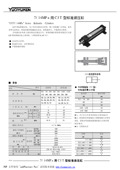
Precision engineering, robust and reliableNowadays sea travel withouthydraulics is unthinkable. Hydrau-lic drive systems are used topower essential operational units on ships. Wherever the situation calls for maximum power in a confined space, Rexroth is there – your competent partner.At Home on the Ocean Wave – Rexroth in Marine TechnologyWorldwide Service2These days ships represent an up-to-the-minute mode of travel. The marine travel sector calls for tech-nically innovative solutions, which meet sea-going requirements in the best possible way. Reliability, robustness, permanent readiness for operation, low-maintenance and long service life – these are the pre-requisites for technical systems of this kind. Hydraulic drive and control solutions meet these re-quirements to a major extent.Our specialists in this sector are used to working with the ship fitters right from the development phase. This is where application-specific know-how and decadesof experience on the part of the Rexroth hydraulics specialists come into their own – with con-vincing results. The ship fitter has at his disposal complete systemsor component solutions based on components specially developed for maritime applications. The most up-to-date calculationprocesses and simulation softwareare used to check these solutionsfor functionality, performance andlife span. Rexroth ensures trouble-free acceptance and certification.Rexroth products for ship travelare low-maintenance, robust andreliable. To ensure their safe usearound the globe there are subsidi-aries in more than 70 countriesoffering on-site consultancy andguaranteeing rapid service andspares deliveries. Leading ship-yards, ship fitters and suppliersall over the world rely on Rexrothsystems to deliver safety and eco-nomic viability on the high seas.Contents:Winches4–5Rudder systems 6Cranes and davits7Hatch covers7Special valves 8Control technology 9Classifications 10Applications example 11Service 12Rexroth systems in marine tech-nology: leading technology handin hand with highly specializedapplications know-how. The rightpartner for the demanding condi-tions at sea.System Know-how Quality and ReliabilityCargo pumpsThrusters and propeller drivesBow and stern doorsBulkhead and hull sealsRoRo equipmentLiftsWater jetMarine diesel controlUnderwater applicationsGenerator drivesCentralized oil supplyBosch Rexroth offers more systemsolutions in the following areas:Winch Drives –Sensitive and ReliableDepending on what the ship is to be used for, Rexroth is able to sup-ply drive solutions for a very wide range of winch systems: • A nchor and mooring winches • F ishery winches • C ranes • T owing winches • D ynamic winches for swell compensation • D eep sea winches • W inch systems for yachts Winches with high pressure hy-draulics are characterized by the fact that they need only a small installation space and that their operation is infinitely controllable and load-independent. Whether it’s compact winches in closed cir-cuit, winch drives in open circuit or secondary control drives for maximum dynamics: Rexroth is the right partner when it comes to winch drives in all performancecategories.Our specialty – compact winches in closed cycle operation Rexroth’s compact winches are characterized by their flexible and straightforward installation. This dispenses with the need for com-plicated pipework.MOBILEX GFT-WHydrostaticMOBILEX gearboxMOBILEX GFT-W- gearboxes are ideal drive components for crane winches with low-noise operation. As a result of their extremely installa-tion-friendly and compact design they can be fitted directly into the cable reels, thus saving space.In addition to an extensive range of standard products, Rexroth offers solutions specially devel-oped for marine applications. This means optimum adaptation of your requirements to the winch drive.44WMM16TH7A10VSO A6VM WCB Winch control block Whether it’s a towline winch with high un-laden rope speed, a mooring winch with automatic rope tight-ening or an anchor winch with an initial break-away torque increased by 50 %: the WCB, with its sea-water-resistant deck construction and mo-dular design, caters for every eventuality, both on its own or when used in combination. The WCB also fea-tures a choice between manual, hydraulic or electric controls.Hydraulic motors The robust A6VM hydraulic motor with its broad adjustment range and high power-density permits high unladen rope speeds.Swashplate pumpThe A10VSO open circuit swashplate pump has proved it-self as a standard for winch units. And this is not the only reason why these pumps have been used for more than 20 years in maritime applications all over the world.Remote control devicesThe TH7 remote con-trol device enables sen sitive control of the winch by using different control curves.Winch valvesThe WMM 16 SO840 proportional valve, featuring an electric or hydraulic remote control facility, has been specially de-veloped to meet the demand for smooth and jerk-free start-up of winch drums. This is in part achieved by means of a particular-ly low-friction valvepiston.5Rudder Systems –Right on Course Maximum maneuverability,optimum efficiency, safety and economy in operation – Rexroth supplies the technology to ensurethat you steer the right course.In order to ensure smooth opera-tion of the rudder system, Rexroth supplies robust and reliable com-ponents reflecting state-of-the-art technology.Proportional valves with integra-ted switch position monitoringSo as to enabling monitoring ofthe function and position of therudder at any time, Rexroth hasopted for the WRZ proportionalvalve with integrated switch po-sition monitoring. This valve hasbeen specially developed for these applications.Axial piston pumpsThe extremely robust and reliable A4CSG axial piston pump, with integral feed pump and valve tech-nology, has proved itself in relation to these applications.CylindersRexroth supplies the right cylinder for all the steering power required. The pressurized parts of the cy-linders are supplied with certified material in accordance with the re-levant classification specifications.A4CSG CylinderWRZ Redundant rudder system for a 7,500 TEUcontainer freighter6Powerful, safe and efficient operation – Rexroth brings motion into play .Turning, lifting, pushing: efficient power application hand-in-hand with maximum reliability in ope-ration– behind all this is Rexroth technology.Power UnitsRexroth supplies matching “power packs” to meet the requirements of every drive in marine techno-logy – manufactured to a uniform standard, as with all our compo-nents and systems. This guarantees economic efficiency, long service life and reliability.Swivel Drives The hydrostatic MOBILEX-GFB swivel drives are used for therotary movements in ships’ cranes and with side rolling hatch cover drives. They have proved them-selves in tough applications and under adverse conditions of use.M4-12MOBILEX-GFBPower Unit Cranes, Davits, Hatch Covers – Motion with Rexroth SystemsHigh Pressure Control BlocksThe crane is controlled by the high pressure control blocks M4-12, 15 and 22 in disc design. These blocks operate with load sensing to save energy. For different loads and where a number of actuators are operated at the same time, load pressure compensation ensures that the same speed can be main-tained. The blocks can be operated mechanically, hydraulically, elec-tro-hydraulically or with on-board electronics. In addition, the M7-22 monoblock with its load-indepen-dent flow distribution ensures that all the actuators can continue to run at a proportionally reduced speed even where the volume flow is insufficient.7Valves and Cylinders with protec-tion against seawater Rexroth offers you a unique range of components featuring protec-tion against seawater. Seawater-resistant steel or even brass is used at critical points in construc-tion. It goes without saying that robust electrical interfaces with corresponding IP Protection are included. For harsh conditions of use in aggressive seawater our cylinders feature the piston rod coating from Ceramax Engineered Coatings, based on the latest oxide coating (plasma).Hydraulics in Special ApplicationsArctic temperatures, extreme con-ditions in relation to pressure in the deep seas, hazardous situa-tions in environments at risk from explosions – everywhere Rexroth components developed specially for your application operate auto-matically, safely and reliably.Special Projects for deep sea applications Deep water projects place particu-lar demands on the components as regards pressure and temperature ratios. Rexroth offers specially designed valves and components for pressure-compensated sub-oil application. With these, usage is possible down to a depth of 3,500 meters.Components for sub-zero temperature applicationsRexroth even supplies solutions and special technologies for use under the harshest conditions of the Arctic regions. These include special valves for open deck appli-cations at ambient temperatures of down to 50 °C below zero.Components in accordance with ATEX DirectivesIn close co-operation with the cus-tomer Rexroth has implemented complete drive and control solu-tions for areas at risk from explo-sions. The products used for this, such as valves, hydraulic cylinders and power units are produced and supplied under strict observance of the ATEX Directive 94/9/EG.8Example: Cargo Pump DriveThe requirements:Control concept for loading and unloading a bitumen and chemi- cal tanker in an area at risk from explosion. Depending on the me-dium to be conveyed, the housing and storage temperatures of the cargo pump, together with the suction and delivery pressure of the pump, must be variable. As bitumen has to be kept permanent-ly at a minimum temperature and circulated, a high level of avail- ability is required.The solution:Visualization via touch panel with bus link to PLC. Inputting of sensor technology in the field via intrinsically safe circuits is followed by processing in the PLC. Monitoring and control of hy-draulics, cooling and lubrication systems. Complete switching sys-tem designed for 300 KW in each case. In order to guarantee the required availability the complete system has been designed so as to be redundant.Control and Automation Technology – Everything to Hand on BoardComplete control and automation technology, along with co-ordi-nated power electronics – with our individual total concepts we offer solutions that provide for the future.Power component with PLC and isolating amplifierClassified Products Bosch Rexroth has decades of experience in working with Clas-sification Societies. Test engi-neers from all the well-known classification societies conductregular acceptance tests at our premises.Rexroth components meet the strict specifications of the Classi-fication Societies as regards design principles, the selection of mate-rials and environmental require-ments for the electronic compo-nents. Right at the beginning of the project the test criteria that are to be observed are defined together with the test engineer. Collabora-tion with the customer at an early stage guarantees that the project runs smoothly and on schedule. Examples of type-tested componentsA4V PumpAxial piston variable displacement pump with hp control for constant power, tested in accordance with Det Norske Veritas.Voith-Schneider propeller used as a ships’s propulsion: Bosch Rexroth supp-lies the system, approved by the Classifi-cation Society, for pitch adjustment of the VSP (power unit, control block and cylin-der). It permits precision control and posi-tioning of the ship.WREA Proportional ValveWREA proportional valve with integrated electronics for position control, tested in accordance with IACS (International Association of Classification Societies) Application example: Voith-Schneider propellerDry Heat: 2 cycles 70 °C (Duration 2 h)Damp Heat: 2 cycles 55 °C Humidity 95 %(Duration 2 h)Cold: 2 cycles –25 °C (Duration 2 h)Vibration: 2 Hz–25 Hz ± 1.6 mm (amplitude)25 Hz–100 Hz ± 4 g (acceleration) Electromagn. Field:80 MHz–2 GHz 10 V/m (field strength)Burst:± 2 kV 5 kHz (spike frequency)(Duration 5 min.)IACS E.10A4VS pump WREA proportional valve10ElectricDrives andControlsHydraulicsLinearMotion andAssemblyTechnologiesPneumaticsService Wherever forces need to be utilizedeconomically, the advantages of in-dustrial hydraulics are obvious –whether it is required to lift and lo-wer loads smoothly, perform linearor rotary movements, achieve con-stant acceleration, maintain givenspeeds, approach positions exactly,transmit powers or interlink se-quences.Rexroth is the technology andmarket leader in industrial hydrau-lics with a comprehensive productrange and distinct applicationexpertise.At Rexroth you can select from theworlds’ largest standard productrange in the field of hydraulics,application and customer-specificsystem solutions of high quality.With advanced micro-electronicsRexroth has made hydraulics evenmore powerful.For you, Rexroth is the ideal partnerfor developing highly efficientmachines and production facilities– from the first point of contact tocommissioning and throughout theentire life cycle. Teams that operateworldwide carry out the completeengineering of your systems and,if requested, up to the hand-overof turnkey systems and beyond –service included.Thanks to the use of hydraulicdrive and control technology fromRexroth you will be more competi-tive than ever.Intelligent Hydraulicsin New Dimensions The Drive & Control CompanyRexroth offers a unique andcomprehensive range of pro-ducts and services acrosstechnologies in its five fields oftechnology and service areas –strong in high-quality individualtechnologies, combined withhighest application-specific com-petence in system packages withintegrated complete solutions.Rely on service acrosstechnologiesRexroth integrates all services forthe entire product spectrum inthe field of factory and industrialautomation into a single organiz-a tion: from immediate support,spare parts service, field andrepair service, retrofit/modern-ization through to training.Bosch Rexroth AG HydraulicsBRH/STI11Zum Eisengießer 197816 Lohr, Germany Phone: +49(0)9352/18-4695 Fax: +49(0)9352/18-1293 ************************ Printed in GermanyRE 09903/11.05 substitutes RE 09903/07.00。