电动汽车充电桩设计外文文献翻译最新译文
- 格式:doc
- 大小:46.50 KB
- 文档页数:9
毕业设计(论文)外文文献翻译文献、资料中文题目:锂电池充电器的设计文献、资料英文题目:The design of the lithiumbattery charger文献、资料来源:文献、资料发表(出版)日期:院(部):专业:班级:姓名:学号:指导教师:翻译日期: 2017.02.14The design of the lithium battery chargerIntroductionLi-Ion rechargeable batteries are finding their way into many applications due to their size, weight and energy storage advantages.These batteries are already considered the preferred battery in portable computer applications, displacing NiMH and NiCad batteries, and cellular phones are quickly becoming the second major marketplace for Li-Ion. The reason is clear. Li-Ion batteries offer many advantages to the end consumer. In portable computers,Li-Ion battery packs offer longer run times over NiCad and NiMH packs for the same form factor and size, while reducing weight. The same advantages are true for cellular phones. A phone can be made smaller and lighter using Li-Ion batteries without sacrificing run time. As Li-Ion battery costs come down, even more applications will switch to this lighter and smaller technology. Market trends show a continual growth in all rechargeable battery types as consumers continue to demand the convenience of portability. Market data for 1997 shows that approximately 200 million cells of Li-Ion will be shipped, compared to 600 million cells of NiMH. However, it is important to note that three cells of NiMH are equivalent to one Li-Ion cell when packaged into a battery pack. Thus, the actual volume is very close to the same for both. 1997 also marked the first year Li-Ion was the battery type used in the majority of portable computers, displacing NiMH for the top spot. Data for the cellular market showed a shift to Li-Ion in the majority of phones sold in 1997 in Europe and Japan.Li-Ion batteries are an exciting battery technology that must be watched. To make sense of these new batteries, this design guide explains the fundamentals, the charging requirements and the circuits to meet these requirements.Along with more and more the emergence of the handheld electric appliances, to the high performance, baby size, weight need of the light battery charger also more Come more big.The battery is technical to progress to also request continuously to refresh the calculate way more complicatedly is fast with the realization, safety of refresh.Therefore need Want to carry on the more accurate supervision towards refreshing the process, to shorten to refresh time and attain the biggest battery capacity, and prevent°from the battery Bad.The A VR has already led the one step in the competition, is prove is perfect control chip of the next generation charger. The microprocessor of Atmel A VR is current and can provide Flash, EEPROM and 10 ADCses by single slice on the market Of 8 RISC microprocessors of the tallest effect.Because the saving machine of procedure is a Flash, therefore can need not elephant MASK ROM Similar, have a few software editions a few model numbers of stock.The Flash can carry on again to weave the distance before deliver goods, or in the PCB Stick after pack carry on weaving the distance through an ISP again, thus allow to carry on the software renewal in the last one minute.The EEPROM can used for conservancy mark certainly coefficient and the battery characteristic parameter, such as the conservancy refreshes record with the battery that raise the actual usage Capacity.10 A/ Ds conversion machine can provide the enough diagraph accuracy, making the capacity of the good empress even near to its biggest capacity. And other project for attaining this purpose, possible demand the ADC of the exterior, not only take up the space of PCB, but also raised the system Cost.The A VR is thus deluxe language but 8 microprocessors of the designs of unique needleobject" C" currently.The AT90S4433 reference The design is with" C" to write, the elucidation carries on the software design's is what and simple with the deluxe language.Code of C this design is very Carry on adjust easily to suit current and future battery.But the ATtiny15 reference design then use edit collected materials the language to write of, with Acquire the biggest code density.An electric appliances of the modern consumption mainly uses as follows four kinds of batteries:1.Seal completely the sour battery of lead( SLA)2.The battery of NiCd3.The NiMHhydrogen battery( NiMH)4.Lithium battery( Li- Ion)At right choice battery and refresh the calculate way need to understand the background knowledge of these batteries. Seal completely the sour battery( SLA) of lead seals completely the sour battery of lead to mainly used for the more important situation of the cost ratio space and weights, such as the UPS and report to the police the backup battery of the system.The battery of SLA settles the electric voltage to carry on , assist limits to avoid with the electric current at refresh the process of early battery lead the heat.Want ~only the electricity .The pond unit electric voltage does not exceed the provision( the typical model is worth for the 2.2 Vs) of produce the company, the battery of SLA can refresh without limit.The battery of NiCd battery of NiCd use very widespread currently.Its advantage is an opposite cheapness, being easy to the usage;Weakness is from turn on electricity the rate higher.The battery of NiCd of the typical model can refresh 1,000 times.The expired mechanism mainly is a pole to turn over.The first in the battery pack drive over.The unit that all turn on electricity will take place the reversal.For prevent°froming damage the battery wrap, needing to supervise and control the electric voltage without a break.Once unit electric voltage Descend the 1.0 Vs must shut down.The battery of NiCd carries on refresh in settling the electric current by forever . The NiMH hydrogen battery( NiMH) holds to shoot the elephant machine 26 such as the cellular phone, hand in the hand that the importance measure hold equipments, the etc. NiMHhydrogen battery is an usage the most wide.This kind of battery permit.The quantity is bigger than NiCd's.Because lead to refresh and will result in battery of NiMH lose efficacy, carry on measuring by the square in refresh process with.Stop is count for much in fit time.Similar to battery of NiCd, the pole turn over the battery also will damage.Battery of NiMH of from turn on electricity the rate and is probably 20%/ month.Similar to battery of NiCd, the battery of NiMH also settles the electric current to refresh .Other batteries says compare in lithium battery( Li- Ion) and this texts, the lithium battery has the tallest energy/ weight to compare to compare with energy/ physical volume.Lithium battery Settle the electric voltage to carry on refresh with , want to have the electric current restrict to lead the heat in the early battery of refresh the process by avoid at the same time.When refresh the electric current.Descend to produce the minimum electric current of the enactment of company will stop refresh.Leading to refresh will result in battery damage, even exploding.The safety of the battery refreshes the fast charge machine( namely battery can at small be filled with the electricity in 3 hours, is usually a hour) demand of the modern.Can to the unit electric voltage, refresh the electric current and the battery temperatures to carry on to measure by。

毕业设计(论文)外文资料翻译系(院):电子与电气工程学院专业:电气工程及其自动化姓名:学号:外文出处:2007 HERE COME THE... CLEANER,GREENER CARS附件: 1.外文资料翻译译文;2.外文原文。
附件1:外文资料翻译译文2007年来了...清洁,环保汽车一个全新的领域,在柴油发动机上使用电气混合燃料电池。
这个说法是针对混合动力汽车:美国人爱他们,不过只是猜测。
一些环保人士一直在疑惑,有没有更大的混合电池组,能不能够直接插在墙上进行充电,能不能提供动力让你开车去上班,电力与小型燃气发动机使其变为可能。
这个概念最初是一个环保主义者的梦想,是来自的费利克斯克莱默,他推动了公用事业支持插件的合作。
但现在电动汽车走向市场,就像其他高科技绿色汽车当年发展的情况一样。
清洁汽车新的一天清洁和环保汽车技术正在蒸蒸日上。
可充电混合动力车,在工业发展上展现了比1900年的黄金岁月高很多的研究和开发热情。
当汽油、蒸汽、电动车在市场上进行竞争,许多公司如通用汽车、还在嘲弄像罗杰和我这样的人,是谁扼杀了电动汽车的发展?事实上,美国通用汽车公司是第一个成功制造出了可充电混合动力车的公司,他们使用了一个有趣的新方法。
他们正在研发一种全新的推进系统,在最近的底特律车展上展示,那就是雪佛兰伏特。
随着seesawing对未来石油和汽油价格的不确定性,美国人终于将注意力集中在寻找燃油经济性车辆和展望他们的下一个大型多功能运动型车。
一个由具有很大影响力的公司JD Power and Associates去年夏天对消费者的调查发现,让人吃惊的是有57%的受访者会考虑购买他们的下一个混合动力汽车,有49%的购车者会考虑E85乙醇动力汽车。
另一项由Frost&Sullivan的调查发现约有80%的人更关注较一年前的燃油价格。
几乎有一半的人说,如果燃油价格持续上涨的话他们会考虑购买更省油的汽车或混合动力汽车。
而从居住在美国的市民的调查中发现,有五分之一的让人印象深刻的说道,他们也开始使用替代交通工具:诸如自行车,步行,公共交通和电动汽车等等。

外文原文Principle, Modeling and Control of DC-DCConvertors for EVZHAN G Cheng-ning , SUN Feng-chun , ZHAN G Wang (School of Vehic le and Transportation Engineering , Beijing Institute of Technology , Beijing 100081)Abstract :DC-DC convertors can convert the EV’s high-voltage DC power supply into the lowvoltage DC power supply. In order to design an excellent convertor one must be guided by theory of automatic control. The principle and the method of design, modeling and control for DC-DC convertors of EV are introduced. The method of the system-response to a unit step-function input and the frequency-response method are applied to researching the convertor’s mat- hematics model and control characteristic. Experiments show that the designed DC-DC convertor’s output voltage precision is high , the antijamming ability is strong and the adjustable performance is fast and smooth.Key words: EV ; DC-DC convertors ; automatic control ; mathematics model ; Bode drawingCLC number : U 469-72 Document code : A Generally there are two power supplies in EV. One is the DC high-voltage power supply that is used by high power devices such as traction motors and air conditioners etc. The other is the DClow-voltage power supply that is usually used in some control circuitand low-voltage electrical devices such as the inst- rument and lighting. It s rating voltage is 24 V or 12 V. The low-voltage power supply can be gained from the high-voltage power supply by aDC-DC conver-tor.In this paper, the main performance of the designed convertor is that the input voltage range is from DC 250 V to DC 450 V , the output voltage is DC 24 V , the maximum output current is DC 20 A , and the output precision is 1 %.1 Principle of the Convertor1.1 The Block Diagram of the DC-DC ConvertorThe block diagram of the DC-DC convertor is showed in Fig. 1. The battery series provide the DC high-voltage input U s. Thelow-voltage output of the con-vertor is U o. The setting value U i of the convertor is equal to or is in proportion to the demanded output voltage U o. The convertor is a closed-loop negative feedback-system with voltage feedback.1.2 Power Switch CircuitThe power switch circuit with semi-bridge mode is showed in Fig. 2. L1 and C1 constitute an input filter to avoid high-frequencyimpulses flowing bac- kwards. Capacitors C2and C3 constitute the partial-voltage circuit while resist-ances R1 and R2do so. IGBT1 and IGBT2 are semiconductor switch devices. C6 is a separation DC capacitor. T1 is a transformer that reduces the voltage. L2 and C7 constitute an output filter. RL is the load resistance. When the PWM signalsin the reverse semi-waves are inputted onto IGBT1 and IGBT2’s control poles , the corresponding DC voltage can be yielded from the convertor.Fig. 2 Principle circuit of power switch with semi-bridge mode 1.3 Control CircuitThe chip SG3525 is used in the PWM control circuit showed in Fig. 3. V cc is the power voltage applied to the chip, it is 12.0 V. A base-voltage of 5.1 V is yielded on pin16 of the chip that is partially used as parameter voltage input U i. The chip includes asawtooth-wave generator. R t and C t are the external resis-tance and capacity that determine the sawtooth-wave’s frequency.Pin2 of the chip is a positive-phase input port. Voltage input U i is putted to the port, here U i =2. 5 V. Pin1 of the chip is the negative-phase input port where the feedback voltage is inputted.Pin9 of the chip is the output end of the inside amplifier of the chip. The proper resistance and capacitor are connected between the pin1 andpin9 to realize compensation of the DC-DC convertor.C8 is the integral capacitor. The integral compensator is adopted as the system-compensation of the system. The PWM impulses are yielded from pin11 and pin14 of the chip. When the PWM control circuit operates normally, U i on the pin2 and U b on the pin1 should be balanced. When U b is not equal to U i , the PWM width can be automatically adjusted by the PWM control circuit to make U b equal to U i. By this way we can control the output voltage of the convertor.Fig. 3 The connection circuit for the PWM control chip SG3525 1.4 Drive CircuitThe drive circuit of IGBT usually adopts a pulse-transformer or an opto-coupler to isolate the power circuit from the control circuit. An individual power supply is needed if an opto-coupler is used, which increases the complexity of the system. So the isolation-circuit adopt s a pulse-transformer showed in Fig. 4. Transistors BG1 and BG2 in Fig. 4 compose a complementation power amplification circuit. T2 is the pulse-transformer that isolates the power circuit from the control circuit. R5 and C8 compose the acceleration circuit. The diode D6eliminates negative impulses. The diode D7 and transistor BG3 compose the rapid discharge circuit of the distributing capacitor at the control pole of IGBT.Fig. 4 Principle circuit for IGBT drive2Modeling and Control2.1 ModelingThe DC-DC convertor is a voltage negative feedback-system. Aiming to obtain the better dynamic and static characteristic we must model and analyse it in theory. According to Ref. [ 1 ] ,DC-DC convertors are the approximate second-order systems. In order to obtain accurate parameters , the method of the system-response to a unit step-function input is adopted in this paper.2.1.1 Measuring the Open-Loop System’s Response to a Unit Step-Function InputThe block diagram for measuring is shown in Fig. 5. The concrete method is described as follows : ①The voltage feedback signal is cut off ; ②The setting value of the chip SG3525 adopts themiddling value U i0 to make the width of an impulse be about 0.5 T ;③U i0 is superimposed with d U i that is composed by positive and negative rectangle wave impulses. The amplitude of d U i is taken to be equal to 0.2U i0. It should make d U o be easy to be observed to select the rectangle wave frequency , adopting f 1 = 400 Hz ; ④The output waveform of U o ( = U o 0 + d U o ) is shown in Fig. 6. As shown in Fig. 6 when f 1 = 400 Hz , period T = 2.5 ms (5 grills) , the time for the maximum voltage value is about 0.2 grills. d U o’s stable voltage amplitude is - grills. Peak overshoot is 1 grill. Every grill in the vertical direction represents 5 V. By this way the data of system-response to a unit step-function input can be obtained as follows :peak time t p = 0.1 ms ; peak overshoot σp = 1/ 2 = 50 %;output and input’s incremental ratio K0 = d U o/ d U i = 10/ 1 = 10.Fig.5 The measuring block diagram of the open-loop systemFig. 6 The system-response to a unit step-function inpu t2.1.2Determining the Open-Loop Transfer FunctionAccording to Ref s. [2,3 ] , we have the damping ratio ξ, undamped natural frequency ωn and transfer function of controlled object G p ( s) as follows :In order to ensure that when the output voltage U o =24 V the feedback voltage to pin1 of the SG3525 is 2.5 V to balance the input voltage U i = 2.5 V, we take the feedback and measuring factor asK b = U b/ U o = -15/ -4 = 01104.( 4 )2.2Design of the PID Regulator2.2.1The Principle Scheme and Transfer Function of the PID RegulatorTo resist the disturbance of the power supply voltage and load current to the DC-DC convertor so as to improve control precision , an integral compensator is adopted. The principle scheme of the integral compensator is shown in Fig. 7.Fig. 7 The principle scheme of the integral compensatorIt s transfer function isG c ( s) = K i/ s = 1/ ( RCs).( 5 )In Fig. 7 and Eq. (5), R = 10 kΩ, C = 0.1μF , K i = 1/ ( RC) = 1/ (10 ×103 ×011 ×10 - 6)= 1 000.2.2.2The Bode Drawing of the System Open-Loop Transfer FunctionThe system open-loop transfer function is the product of the controlled object’s , feedback and measuring circuit’s and integral compensator’s transfer functions. We haveG( s) = G c ( s) G p ( s) G b ( s) =The system Bode drawing is shown in Fig. 8 from Eq. (6). The curves ①and ④are respectively the logarithmic gain-frequency characteristic ,logarithmic phase-frequency characteristic of controlled object G p ( s). The curves ②and ⑤are respectively the logarithmic gain-frequency characteristic , logarithmicphase-frequency characteristic of the feedback and measuring circuit joint the integral compensator. The curves ③and ⑥are respectively the logarithmic gain-frequency characteristic and logarithmic phase-frequency characteristic of the compensatedopen-loop system. By Fig. 8 we know that the system is I-model system. When the input doesn’t change , there isn’t steady-state error. It s original phase-margin frequency ωc = 1 016 rad/ s , phase margin γ= 89.21°, so the adjustable performance of the system is fast and smooth.Fig. 8 The Bode drawing of the system open2loop transfer function 3 The Result and Conclusion of ExperimentWhen the load resistance R L = 1.2Ω, the experiment data of U s , I s , U o , I o , η(ηis efficiency of the convertor) are shown in Tab. 1. When the load resistance R L = 2.4Ω, the experiment data ofU s , I s , U o , I o , ηare shown in Tab.2.4 Conclusions①Because the integral compensator is adopted , the output voltage U o of the convertor has quite high precision even if the input power voltage and the load changes.②The width of the impulses is adjusted automatically in the convertor to realize constant output voltage value. With the increase of the input voltage the width of the impulses turn narrow , the convertor’s efficiency drops. In the process of designing a DC-DC convertor, we must diminish the adjustable range of the impulse width and make the impulse width wider when the convertor operates.③The reasonable value of the resistance and capacitor in the feedback circuit must be selected so that the feedback-system has enough gain margin and phase margin that can guarantee thecontrol-system to be adjusted smoothly.References:[1 ] Cai Xuansan , Gong Shaowen. High-frequency electronics (in Chinese) [ M].Beijing : Science Press , 1994. 232 - 246.[2] Zhang Wang , Wang Shiliu. Automatic control principle (in Chinese)[M]. Beijing: Beijing Institute of Technology Publishing House , 1994. 71 - 72.[3 ] D’Azzo J J. Linear control system analysis and design [M]. San Francisco: McGraw-Hill Book Company,1981. 83 - 92.电动汽车DC-DC电源转换器的原理、建模和控制张承宁, 孙逢春, 张旺(北京理工大学车辆与交通工程学院, 北京100081)摘要:为了设计出在电动汽车上把高压直流电源变换成低压直流电源的高品质DC-DC 变换器,采用自动控制理论进行指导. 介绍电动汽车DC-DC 变换器原理和设计,建模与控制方法. 应用阶跃响应法、频率法研究其数学模型和控制特性,并且进行分析和计算. 实验结果表明,用这种方法所研制的电动汽车DC-DC 变换器输出电压精度高,抗干扰能力强,调节特性快速、平稳.关键词:电动汽车; DC-DC 变换器; 自动控制; 数学模型; Bode 图中图分类号U 469172 文献标识码A通常有两种电源电动汽车。
文献出处:Pollet G. The research of electric car charging system and controller [J]. Electrochimica Acta, 2015, 5(3): 235-249.原文The research of electric car charging system and controllerPollet GAbstractThis paper puts forward the whole bridge main circuit topology and PWM control method effectively improves the reliability of the charging system and efficiency. Put forward and realized based on digital signal processing chip controller circuit intelligent PI control algorithm and variable parameters, significantly improve the control precision of the charging system voltage, current and response characteristics. Double proposes a CAN bus and RS - 485 bus communication network, realized the distributed control of the process of charging, the charging operation is flexible and reliable. Due to be able to provide a communication interface to battery management system and algorithm, charging system according to the state change of battery charging mode, optimizing the charging mode. The success of the charging system has important theoretical significance and engineering value. Keywords: Electric cars; Charging system, PWM, Intelligent PI, Distributed control 1 IntroductionElectric car, it is all or part of the electric drive system of power car, compared with conventional cars powered by gasoline as, electric cars in such aspects as environmental protection, clean, energy-saving occupy obvious advantages. Now each big international automobile manufacturer have invested a lot of money and manpower to electric car research and development, a variety of the electric car prototype appeared frequently, some have reached high industrialization scale. Now the development of the electric car industry has formed a hybrid vehicles, pure battery-powered electric vehicles (electric cars) and three main direction of fuel cell electric vehicles. Pure electric vehicle itself is not harmful gas emissions, can make full use of surplus power in the evening, improve the efficiency of energy utilization, and improve the economic benefit. Pure electric vehicles completely eliminateemissions of the vehicle running, fully use of secondary energy electricity, in line with the energy sustainable utilization strategy, along with the progress of the technical level, the pure electric vehicles has a broad development prospects. But at present, the development of the battery and charging system can't satisfy the requirement of electric cars, there are some theoretical and technical problems have yet to be research, serious lack of relevant standards and norms, has become the bottleneck of affecting the development of electric vehicles.2 The current situation of the electric vehicle charging systemAt the beginning of last century, as the secondary battery research is successful, and matching charging system arises at the historic moment. The charging system using the conventional charging method, which is USES small current for a long time to recharge battery. This way of charge due to the charging time is too long, can not meet the requirement of the electric cars and so on, the demand of the quick charge. Widely at home and abroad to carry out the study of fast charging system. Fast charging system produce roughly experienced three stages of development:(l) Groping stageIs the earliest in the 50 s of the last century, the United States as a result of the need of military, began to study fast charging technology, made the metal rectifying shape fast charging system, for 6 to 24 v lead-acid battery quick charging, the weight of 40 kg, have fast, medium and slow three charging modes.(2) The theory research stage1967 U.S. troops (Mas) have bubbles in the process of charging is studied, find the reason and law of gas, on the premise of minimum gas rate and find out the maximum charging current of battery can accept and acceptable charging current curve, discusses the theory of quick charge battery, and on the basis of practice, put forward the basic rules of quick charge battery.(3) The practical application stageMcCulloch electronic companies in the United States in 1970 made the lead-acid battery quick charging system, for 500A to 190AH battery charging current, and in 1200A discharge to deal with the polarization current for short periods of time, theresults 30 minutes to put the battery is good. In addition to the United States, such as Japan, other countries such as Britain, France, Germany, the former Soviet Union also has different degree of development in rapid charging technology. Britain's associated company invented "TEC total energy intelligent charging control technology" and its control system, effectively control the powder charging when the amount of energy needed, overcome existing corona charging system and friction type charging system caused various problems, to solve the "Faraday shielding effect" and "reverse ionization effect" and so on.At present the batteries of electric cars in use process, because of the limitation of the voltage of the power battery energy and need to adopt more battery in series combination, and power battery characteristics of highly nonlinear, individual difference is very big, therefore become the electric car battery management system, a necessary device. The most basic function of BMS is to monitor the working state of the battery (voltage, current and temperature of the battery), prediction of power battery (SOC) of battery capacity, battery management to avoid over discharge, overcharge, overheating and serious imbalance between monomer battery voltages, maximize battery storage capacity and cycle life.Current of the electric vehicle charging system is not very good with a serious defect currently has been relatively mature and supporting the use of on-board BMS system, charging system is either not provide communication interface with BMS, or communication interface is not compatible with popular now BMS interface. BMS system has the most comprehensive, full of battery state of real-time data, if you can provide the charging system and its communication interface, can fundamentally solve the current charging system in the process of charging the battery status change resulting in without understanding the state of the battery charged blindly charging, thus reduce battery life.In addition, as the core of the electric vehicle charging system, the existing charging controller, the control process are mostly based on analog signal processing, and its control structure is a centralized control structure. The traditional charging system boundary is not clear, complex structure and each subsystem is unitized degreeis very low. Its applied electromagnetic environment, all kinds of high frequency signals could easily lead to serious interference of microcomputer control charging system failure. In the past, often using analog signal for each signal transmission is between the control systems. Various kinds of interference signal into analog signals, it is easy to lead to failure of the control system, its structure and the process may not apply to the requirement of the distributed control and the whole process of the digital processing requirements.3 The function of the electric vehicle charging system requirementsThe charging system in addition to providing communication interface with BMS, received by the BMS battery status parameters of transfer function, extract energy from power supply and charging system is passed to the battery in the right way, so as to set up between power supply and battery power conversion interface. Charging system is usually performed by the power conversion unit and process control of controller. The basic properties of the charging system requirements include the following:Security: electric vehicle charging, how to ensure that personnel's personal safety and the safety of the battery is very important. Easy to use: charging system should have high intelligence, operators don't need too much intervention in the charging process. Cost economy: economic and cheap charging system helps to reduce the cost of the whole electric cars, improve operation efficiency, and promote the commercialization of electric vehicles. High efficiency: efficiency is one of the most important requirements for modern charging system; the efficiency of the energy efficiency of high and low for the electric car has a huge impact. Low pollution to the power supply: the power electronic technology of the charging system is a kind of highly nonlinear devices, will produce harmful to the supply network and other electrical equipment of the harmonic pollution, moreover, because of the charging system power factor is low, the charging system load increases, its effect on the supply network also not allow to ignore.4 EV charging method4.1 Constant current chargingIn the whole process of charging and is always with constant current for rechargeable battery. In this way, to ensure that in the later stages of charging without a lot of gas, therefore can only use small current charging, so need a long time, the charging method has the advantage of simple operation, the current is too small, but in the beginning in the late charge and charging current is too large, charging time is long.4.2 Constant voltage chargingEarly charging current is quite large, as the charge and current decreases. For more battery discharge, the initial charging current is too large in order to protect cells from damage, at the beginning of the charging to limited flow measures to avoid the charging current is too large. Compared with constant current charging, the battery is not easy to calculate.4.3 Constant voltage charging current limitingTo remedy constant-voltage charging shortcomings, is widely used in constant voltage current limiting method. Set the maximum charging current, at the beginning of the charge, when the current exceeds the limit of flow value, with the current limiting value, when the current less than the current limit value, constant voltage charging. Thus automatically adjust the charging current, does not exceed a certain limit, the charging current is controlled in the early.4.4 Constant voltage charge after constant currentThis method is a combination of constant current charging and constant voltage charge, the previous constant current charging and accounting period of constant voltage charging way, on the one hand to avoid the constant voltage charging current is too large, in the early late again on the other hand to avoid the constant current charging phenomenon.4.5 Charge attenuationIn the process of charging, with the increase of voltage of the battery, charging current attenuation of charging method gradually. This is a kind of ideal charging method; charge saves time and prevents the sulfuric acid stratification and the plate vulcanizing. But this charging method implementation requires more complex control,compared with the constant current charging; the charging amount is not easy to estimate. Due to the battery and nonlinear dispersion, complexity, the problems in the process of charging, the battery charging has become a more complex issue. The traditional charging method is used to charging very troublesome, because often be charging for 10 hours, and in the process of charging must be manned. Quick charge is the problem to be solved in the process of charging current control, in the process of charging, if the charging current is not enough, to reach the purpose of quick charge. If the charging current is too large and will cause a large number of precipitation of gas, electrolyte temperature will rise quickly, easy to cause the battery plate is damaged, shorten the battery life. Also in the process of charging battery monomer battery consistency of difference, this factor must be fully considered.译文电动汽车充电系统及控制器研究Pollet G摘要本文提出了全桥的主电路拓扑结构和PWM的控制手段,有效的提高了充电系统的可靠性和效率。
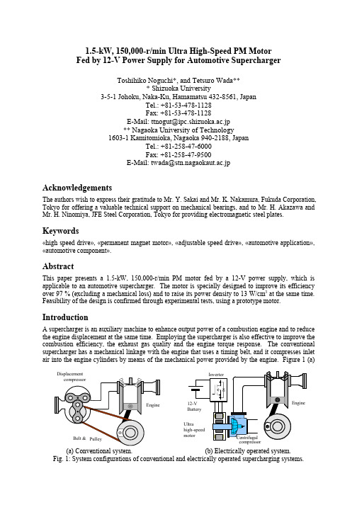
1.5-kW, 150,000-r/min Ultra High-Speed PM Motor Fed by 12-V Power Supply for Automotive SuperchargerToshihiko Noguchi*, and Tetsuro Wada*** Shizuoka University3-5-1 Johoku, Naka-Ku, Hamamatsu 432-8561, JapanTel.: +81-53-478-1128 Fax: +81-53-478-1128E-Mail: ttnogut@ipc.shizuoka.ac.jp ** Nagaoka University of Technology1603-1 Kamitomioka, Nagaoka 940-2188, JapanTel.: +81-258-47-6000 Fax: +81-258-47-9500E-Mail: twada@stn.nagaokaut.ac.jpAcknowledgementsThe authors wish to express their gratitude to Mr. Y. Sakai and Mr. K. Nakamura, Fukuda Corporation, Tokyo for offering a valuable technical support on mechanical bearings, and to Mr. H. Akazawa and Mr. H. Ninomiya, JFE Steel Corporation, Tokyo for providing electromagnetic steel plates.Keywords«high speed drive», «permanent magnet motor», «adjustable speed drive», «automotive application», «automotive component».AbstractThis paper presents a 1.5-kW, 150,000-r/min PM motor fed by a 12-V power supply, which is applicable to an automotive supercharger. The motor is specially designed to improve its efficiency over 97 % (excluding a mechanical loss) and to raise its power density to 13 W/cm 3 at the same time. Feasibility of the design is confirmed through experimental tests, using a prototype motor.IntroductionA supercharger is an auxiliary machine to enhance output power of a combustion engine and to reduce the engine displacement at the same time. Employing the supercharger is also effective to improve the combustion efficiency, the exhaust gas quality and the engine torque response. The conventional supercharger has a mechanical linkage with the engine that uses a timing belt, and it compresses inletair into the engine cylinders by means of the mechanical power provided by the engine. Figure 1 (a)Fig. 1: System configurations of conventional and electrically operated supercharging systems.illustrates a mechanical configuration of the conventional supercharging system. As shown in the figure, many of the superchargers employ a positive displacement compressor because its operation speed is limited by a low revolution speed of the engine. However, the positive displacement compressor has drawbacks such as lower efficiency and lower boost pressure than those of a centrifugal compressor, which prevents further performance improvement of the supercharging system. In order to solve these problems, electrification of the supercharger is significantly important and is very promising approach as a next-generation auxiliary machine system for future automobiles. Figure 1 (b) shows an outline of the electrically operated supercharging system where an ultra high-speed permanent magnet (PM) motor is used to drive the centrifugal compressor instead of the conventional positive displacement compressor. Since the electrically operated supercharger allows use of the centrifugal compressor and makes a mechanical-linkage-free system possible, many advantages are obtained, e.g., more efficient operation, higher rotation speed, higher boost pressure, faster response of the inlet air compression, and smaller mechanical dimensions than those of the conventional displacement compressor based system. Furthermore, such a mechanical-linkage-free design gives freedom of mechanical placement around the engine, and makes it possible to reduce overall mechanical losses as well as to eliminate the complicated linkage mechanism.This paper discusses an optimum design of the ultra high-speed PM motor of which specific application is the electrically operated supercharger of the automotive engine. The motor is fed by a three-phase inverter with a 12-V battery as a DC power supply for an automotive application; thus the motor design must meet a high-current and high-frequency operation requirement without sacrificing the motor efficiency and power density. The investigated motor has a rated output power of 1.5 kW and the maximum rotation speed of 150,000 r/min, respectively. In order to achieve this goal, various technical issues must be solved, e.g., drastic reduction of the synchronous impedance, minimization of the iron and the copper losses, further improvement of the motor efficiency and the power density, mechanical stabilization in high-speed operation range, and so forth. In addition, these electrical design requirements must be satisfied all together with a compact and robust mechanical design. On the way of optimization process in the machine design, a finite element method (FEM) based electromagnetic field analysis is conducted to make fine-tuning of the detailed motor shape and to maximize the efficiency and the power density at the same time. Consequently, the efficiency has been improved over 97 % (excluding a mechanical loss) and the power density has been raised to approximately 13 W/cm3 in the prototype motor design.Required Specifications of Ultra High-Speed PM MotorAssuming a 1,500-cc class automotive engine, the ultra high-speed PM motor is required to have the rated power of 1.5 kW at the maximum rotation speed of 150,000 r/min to achieve the electrically operated supercharging system. When boosting the inlet air compression, extremely fast response is required because the compressor must be accelerated from several ten thousand r/min to the maximum rotation speed in approximately 0.5 s, which surpasses a response time of the conventional supercharger. In order to meet this requirement, the motor must have a short-duration overload capacity, which is a double of the rated output power for 1 s. Table I shows target specifications of the motor determined by the above requirement.Basic Design Concept of Ultra High-Speed PM MotorIn order to achieve the highest efficiency and the highest power density among various sorts of electric motors, a two-pole three-phase surface permanent-magnet synchronous motor (SPMSM) is focused on Table I: Specifications of developed ultra high-speed PM motorAssumed engine 1500 cc classRated output power 1.5 kWMaximum rotation speed 150,000 r/minRated torque 0.0955 NmOverload capacity and duration 3 kW (200 % load) for 1 sas the best choice for the ultra high-speed motor drive because of the simple rotor structure and no magnetizing current required, which implies higher efficiency than other motors.The stator has a six-tooth six-slot structure and concentrated windings, which is remarkably effective to reduce the copper loss and the leakage inductance thoroughly as well as the synchronous inductance. Each phase has a pair of single or double-turned windings in parallel, and the windings are not ordinary wires but copper bars of which shape is like an alphabetical letter “b.” It is necessary to reduce as much stator iron loss as possible even at 150,000 r/min operation, so high-performance 6.5-% silicon electromagnetic steel plates of which thickness is only 0.1 mm are employed to compose a laminated stator iron core.On the other hand, the rotor consists of a strong Nd-Fe-B permanent magnet and a molybdenum alloy shaft. Use of the Nd-Fe-B permanent magnet allows not only motor efficiency improvement but also drastic reduction of the rotor size and inertia. In addition, such a strong Nd-Fe-B permanent magnet that has BH max = 310-kJ/m 3 makes it possible to widen the air gap, which is essential to reduce the synchronous inductance and to obtain a sinusoidal electromotive force (e.m.f.) regardless of the concentrated stator winding structure.Table II is a summary of the basic conceptual design parameters of the ultra high-speed PM motor to be investigated in this paper.Optimization of Permeance Coefficient and Stator WindingsSince a permeance coefficient determines an operating point on a B-H curve of the permanent magnet, operation characteristics of the PM motor dominantly depend on the permeance coefficient. The permeance coefficient is basically proportional to the e.m.f. unless other physical dimensions of the investigated motor are changed. Therefore, the permeance coefficient has a strong influence on the motor efficiency because there is a trade-off relationship between the copper loss and the iron loss of the motor, depending on the e.m.f. Assuming that the investigated PM motor has a uniform permeance distribution along the air gap, the permeance coefficient p u of the motor is expressed by the following equation:gC g m mmmgC g mm u K D D K a a p ll l l l l +−==, (1)where ℓm is a permanent-magnet thickness, a m is an averaged cross section area of the permanentmagnet, a g is an averaged cross section area of the air gap between the rotor and the stator, ℓg is a radial air gap length, D m is an outer diameter of the permanent magnet, and K C is a Carter’s coefficient. Since K C normally takes a value of approximately 1.2 to 1.5, a g can be regarded as almost same as a m K C ; thus, the following approximated expression is obtained:g m u p l l≈. (2)This equation shows that the permeance coefficient is determined by the ratio between the permanent-magnet thickness and the radial air gap length as illustrated in Fig. 2.Table II: Conceptual design parameters of developed ultra high-speed PM motorMotor type Surface Permanent-Magnet Synchronous Motor (SPMSM)Number of phases 3 phase Number of poles 2 pole Stator winding configuration ConcentratedWinding configuration 1- or 2-turn windings in parallel per phaseElectromagnetic steel plates10JNEX900(0.1-mm thick, 6.5-% silicon, µs = 23,000, B max = 1.8 T)Permanent magnetNd-Fe-B N-39SH(Br = 1.28 T, bHc = 955 kA/m, BH max = 310 kJ/m 3)BearingsAngular ceramic-ball bearings with grease lubricationThe synchronous impedance of the investigated PM motor must ultimately be reduced because the motor is operated under high-current and high-frequency operation conditions. Otherwise, it is impossible to satisfy the target specifications, delivering the rated power of 1.5 kW at the maximum rotation speed of 150,000 r/min with a 12-V DC power supply. This ultimately low synchronous impedance can be accomplished by having a wide air gap owing to such a strong Nd-Fe-B permanent magnet as BH max = 310 kJ/m 3, and by reducing the number of winding turns drastically. Figure 3 (a) indicates a stator winding configuration, where two models of the winding structure are illustrated in the same figure, i.e., a one-turn and a two-turn structures. The copper-bar windings are cut out of bulk copper plates so that their shape is like an alphabetical letter “b” as illustrated in Fig. 3 (b). The leakage inductance can effectively be reduced by inserting these windings closely to teeth of the stator iron core.In general, a back e.m.f. of the PM motor is expressed as follows:g w N k p E e φω22==,(3)where p is the number of pole pairs, ω is an operation speed in rad/s, k w is a winding coefficient, N is the number of winding turns and φg is an air gap magnetic flux. As the above equation indicates, the back e.m.f. can be enlarged by increasing Ν or φg . Therefore, the two configurations of the stator windings shown in Fig. 3 (a) are investigated from the viewpoint of the efficiency and power density maximization and the voltage utilization of the inverter output. Suppose that each motor line current is controlled to be in phase with the back e.m.f. of the corresponding phase, the total phase voltage including a voltage drop of the inverter can be expressed by the following equation:E I L I R I R V a a FET +++=ωj ,(4)where R FET I is a voltage drop of the MOSFETs used in the inverter (approximately 2 m Ω/phase), R a I is a voltage drop of the stator winding resistance, ωL a I is a voltage drop of the stator winding inductance, and E is the back e.m.f. The voltage drops of the motor with one-turn stator windings are listed in the left column of Table III. As can be seen in the table, the voltage drop due to the synchronousinductance is hardly observed as well as the leakage inductance drop. In addition, the back e.m.f. ismFig. 2: Cross section diagram to investigate permeance coefficient.2 turnWinding Stator teeth(a) Stator core and windings. (b) Stator winding.Fig. 3: Stator winding configuration.unnecessarily too low to utilize the DC power supply voltage. Therefore, since both of the leakage inductance and the synchronous inductance are sufficiently small, it is possible to operate the motor with a 12-V DC power source even if the number of turn is double as indicated in the upper part of Fig. 3 (a), resulting in quadruple synchronous inductance and twice in the back e.m.f. In addition, changing the permeance coefficient p u from 1.67 to 0.882 to improve the motor efficiency, the voltage drops of the motor with the two-turn stator windings are as listed in the right column of Table III. As described previously, the winding resistance and the inductance become 4 times of those in the one-turn motor, but the increase of these voltage drops can be restricted within 2.5 times to 2.9 times because the operating current is effectively reduced by approximately 30 % by optimizing the back e.m.f. Assuming that the maximum phase voltage applied to the motor is 4.9 V rms , which can be fed by the inverter with the 12-V DC power supply, it is possible to utilize 90.0 % of the 12-V power supply voltage at 1.5-kW operation and to utilize 97.5 % even in a 200-% over load condition without a voltage saturation.Optimization of Detailed Dimensions for Power Density MaximizationIn order to maximize the power density of the motor without sacrificing the efficiency, the detailed stator iron core shape, i.e., a yoke width, a outer diameter and a tooth width, is investigated through FEM based electromagnetic analyses as shown in Fig. 4. The stator inner diameter is fixed at 28 mm, which is derived from the calculation result of the permeance coefficient described above and the stack length of the stator iron core is limited to 30 mm to prevent harmful mechanical vibrations of theO u t e r d i a m e t e r ( 70 m m )ShaftWinding Teeth widthFig. 4: Cross section diagram of 2-turn PM motor.Table III: Voltage drops per phase at rated operation and other design parametersNumber of winding turns 12Resistance of inverter MOSFET R FET2 m ΩStator winding resistance R a 0.072 m Ω 0.200 m Ω Stator winding inductance L a 0.070 µH 0.294 µH Voltage drop of inverter MOSFET R FET I 0.353 V 0.243 V Voltage drop of the stator winding resistance R a I 0.0127 V 0.0243 V Voltage drop of the stator winding inductance ωL a I0.194 V 0.562 V Back e.m.f. E 2.84 V 4.11 V Total voltage drop V 3.21 V 4.41 V Stator iron core stack length L 30 mmPermanent-magnet thickness ℓm5 mm 3.75 mm Radial air gap length ℓg3 mm4.25 mmPermeance coefficient p u 1.67 0.882rotor shaft over the whole operation speed range. Figure 5 shows loss analysis results of the motor with respect to the specified dimension of the stator iron core.Figure 5 (a) shows electrical losses of the motor when only the stator yoke width is changed while other parameters, i.e., the stator outer diameter and the tooth width, are kept constant. As the stator yoke gets wider, the iron loss gradually decreases because the magnetic flux density is reduced in the iron core, but the copper loss becomes dominant among the losses. Since the copper loss is affected by the slot cross section area for the windings, the wider stator yoke reduces the slot cross section area, resulting in higher current density and higher resistance of the windings. On the other hand, when the stator yoke is too narrow, the motor is unable to deliver the torque due to the magnetic saturation in the stator yoke. Therefore, it can be found that 6 mm is the best value for the stator yoke width.Keeping the stator yoke width at 6 mm, a loss analysis result is shown in Fig. 5 (b) as the stator outer diameter is changed. The reduction of the stator outer diameter makes the total iron core loss less because the magnetic flux path gets shorter together with whole volume of the motor. However, the percentage of the copper loss becomes more remarkable as the stator outer diameter gets smaller. The reason of this copper loss enlargement is excessive reduction of the slot cross section area for the windings. Therefore, the stator outer diameter of 70 mm takes the minimum loss, which is the most effective to optimize the overall motor dimensions from the viewpoint of the efficiency and the power density.L o s s (W )Back yoke width (mm)(a) Loss analysis result with respect to back yoke width.L o s s(W )Stator core outer diameter (mm)(b) Loss analysis result with respect to stator outer diameter.102030405060L o s s (W )Teeth width (mm)(c) Loss analysis result with respect to teeth width.Fig. 5: Loss analysis results with respect to detailed stator iron core shape.In a similar way, the tooth width can be determined to be 10 mm to minimize the total loss. As the tooth width gets narrower, it is found that the eddy current loss on the rotor permanent magnet becomes higher. This is because the wider slot opening due to the narrower tooth causes more detrimental permeance variation along the air gap.Consequently, the detailed stator iron core and rotor dimensions are summarized as listed in Table IV. Since the total volume of the stator and the rotor including the air gap is only 115.5 cm3, the power density at the rated output power reaches 13W/cm3, which is approximately 10 times of that of common electric machines. The outer diameter of the rotor is as small as 19.5 mm; thus, the circumference velocity of the rotor reaches 153.2 m/s, which is less than half of the sound speed. As described later on, however, the rotor is mechanically reinforced by glass fiber threads with epoxy resin to prevent the permanent magnet rotor from destruction due to large centrifugal force.Figure 6 shows loss comparison at the rated operating condition between the one-turn and the two-turn motors designed in this investigation. As can be seen in the figure, the two-turn motor achieves drastic reduction of the electrical losses down to 36 W, compared with those of the one-turn motor, i.e., 62 W. The copper loss of the two-turn motor is enlarged because of the small slot cross section area, but each of the eddy current loss on the rotor permanent magnet and the stator iron core loss is effectively reduced. It is inferred that the total efficiency of the designed two-turn motor excluding a mechanical loss reaches 97.6 % although the motor is driven by such a low-voltage DC power supply as a 12-V battery.Prototype Ultra High-Speed PM MotorAs described in the basic design concept, the prototype has a special electrical and mechanical structure. Figure 7 shows photographs of the prototype. The laminated stator iron core consists of approximately 300 sheets of 6.5-% silicon electromagnetic steel plates, of which outer diameter is 70 mm, inner diameter is 28 mm, and axial stack length is 30 mm. The stator winding copper bars are inserted in the stator teeth with keeping electrical insulation from the stator iron core by polyimide taping, and are connected to a neutral-point end ring all together. Each of the stator windings has a cross section area of 16 mm2, resulting in a current density of 7.6 A/mm2 at the rated operating condition. Every clearance between each tooth and each stator winding is less than 0.3 mm, which effectively improves the magnetic coupling with reducing the leakage flux.On the other hand, the rotor is simply assembled with a ring-shaped Nd-Fe-B permanent magnet and a molybdenum alloy shaft, and is magnetized so that the flux distribution becomes sinusoidal. After assembling the rotor, 2.5-mm thick layer of the non-electrically-conductive glass fiber is formed with special epoxy resin on the permanent magnet surface against large centrifugal force. Mechanical reinforcement with glass fiber can be seen in the photograph of the rotor exterior.Table IV: Summary of designed dimensionsStator outer diameter DO70 mm Stator stack length L 30mmmm Stator inner diameter DI28 mm Rotor PM outer diameter dO 19.5mm Rotor PM thickness mStator yoke width YW 6l 3.75 mmmm Radial air gap length g l 4.25 mm Stator tooth width TW 10Fig. 6: Loss comparison between one-turn and two-turn motors at rated operating condition.Figure 8 illustrates a three-dimensional computer graphic (a bird’s-eye view) of the prototype motor assembly. All of the metal components are made with a high-precision NC machining tools. The prototype is designed and created to have extremely high mechanical accuracy of µm-order, especially in the bearing brackets and the rotor shaft parts.Experimental Setup and Test ResultsFigure 9 shows a schematic diagram of an experimental setup to confirm basic operation characteristics of the prototype motor. A pseudo current-source inverter was employed to drive the motor because of a high-fundamental-frequency over 2 kHz and extremely low-synchronous inductance. The pseudo current-source inverter consists of a current-controlled buck-boost chopper and a six-step inverter. The former is operated with a DC-bus current feedback at a switching frequency of 48 kHz, resulting in significant reduction of the DC-bus reactor inductance. The latter commutates the DC-bus current and generates 120-deg conduction patterns of the motor line currents. Surge voltages during the current commutation are clamped by the DC-bus power source via MOSFETs’ body diodes and a bypass diode in the chopper.Table V represents comparison between the designed and the measured motor parameters. As listed here, the measured motor inductance is slightly higher than the designed value because of the leakage inductance and the line inductance to the motor.(a) Stator iron core with two-turn windings. (b) Nd-Fe-B PM rotor reinforced by glass fiber.(c) Front and rear views of assembled motor.Fig. 7: Photographs of prototype ultra high-speed PM motor.Fig. 8: Three-dimensional computer graphic of motor assembly.Figure 10 shows steady-state waveforms of the Hall-effect position sensor signal, the line current and the terminal voltage of the motor operated at 150,000 r/min under no load condition. As can be seen in the figure, the 120-deg current pattern is properly generated in synchronism with the Hall-effect position sensor signal. The motor terminal voltage is sinusoidal without a conspicuous harmonic distortion, which implies the back e.m.f. is properly generated so as to be a sinusoidal waveform by the rotor permanent magnet regardless of the concentrated winding structure of the stator.Figure 11 shows an acceleration test result, which was conducted to examine the output torque controllability. Since measuring the mechanical output at such an ultra high-speed as 150,000 r/min is rather difficult, the output torque of the prototype motor was estimated by a designed value of the rotor inertia and an acceleration observed in the speed step response. As shown in the figure, it is inferred that the maximum output torque delivered for the acceleration was approximately 0.08 Nm due to the current limit of the inverter, which was 84 % of the rated value. Although the estimated output torque waveform is choppy, it can be found from the waveform envelope that the speed is linearly regulated. ConclusionThis paper discussed an optimum design to develop a 1.5-kW, 150,000-r/min ultra high-speed PM motor fed by a 12-V DC power source, which is applicable to an automotive supercharger, from the viewpoint of efficiency and power density improvement. The prototype has various unique features in its electrical and mechanical structure, which achieves a low-voltage, high-current and high-frequency operation. Owing to the optimum design of the permeance coefficient and the detailed stator iron core shape, the designed motor can achieve an ultimately high power density of 13 W/cm3 together with a remarkably high efficiency over 97 % (excluding a mechanical loss). The maximum-speed operation under no-load condition and a speed step response with a 84-% output torque delivered were experimentally examined, and proper operation characteristics were confirmed through the experimental tests.ωmTable V: Measurement result of two-turn motor parametersMotor parameters Designed value Measured valueE.m.f constant 2.74 x 10⁻⁵ V/r/min 2.67 x 10⁻⁵ V/r/minStator winding resistance R a0.200 mΩ 0.151mΩµHStator winding inductance L a0.294 µH 0.362References[1] M. Okawa, "Design Manual of Magnetic Circuit and PM Motor," Sogo Research , 1989 (in Japanese).[2] I. Takahashi, T. Koganezawa, T. Su G., and K. Ohyama, “A Super High Speed PM Motor Drive System by a Quasi-Current Source Inverter,” IEEE Transactions on Industry Applications , Vol. 30, no. 3, p.p. 683-690, 1994. [3] B. -H. Bae, and S. -K. Sul, “A Compensation Method for Time Delay of Full-Digital Synchronous Frame Current Regulator of PWM AC Drives,” IEEE Transactions on Industry Applications , Vol. 39, no. 3, p.p. 802-810, 2003.[4] B. -H. Bae, S. -K. Sul, J. -H. Kwon, and J. -S. Byeon, “Implementation of Sensorless Vector Control for Super-High-Speed PMSM of Turbo-Compressor,” IEEE Transactions on Industry Applications , Vol. 39, no. 3, p.p. 811-818, 2003.[5] T. Noguchi, Y. Takata, Y. Yamashita, Y. Komatsu, and S. Ibaraki, "220000r/min, 2-kW Permanent Magnet Motor Drive for Turbocharger", IEE-Japan International Power Electronics Conference (IPEC2005) -Niigata , p.p. 2280-2285, 2005.[6] C. Zwyssig, M. Duerr, D. Hassler, and J. W. Kolar, “An Ultra-High-Speed, 500000 rpm, 1 kW Electrical Drive System,” The Fourth Power Conversion Conference (PCC2007) -Nagoya , CDROM, 2007.[7] T. Noguchi, and M. Kano, “Development of 150000 r/min, 1.5 kW Permanent-Magnet Motor for Automotive Supercharger,” The Seventh International Conference on Power Electronics and Drive Systems (PEDS2007) -Bangkok , 2A-03, 2007.0.00.40.8 1.2 1.6 2.0-30-20-100102030-15-10-5051015-20246 L i n e c u r r e n t (A )Time (ms)T e r m i n a l v o l t a g e (V )S e n s o r s i n g n a l (V )Fig. 10: Operating waveforms at 150,000 r/min under no load condition.2000025000300003500040000450000.00.20.40.60.81.00.000.020.040.060.080.10R o t a t i o n s p e e d (r /m i n )E s t i m a t e d o u t p u t t o r q u e (N m )Time (s)Fig. 11: Speed step response and experimentally estimated output torque.。

电动汽车中英文对照外文翻译文献(文档含英文原文和中文翻译)电动车:正在进行的绿色交通革命?随着世界上持续的能源危机,战争和石油消费以及汽车数量的增加,能源日益减少,有一天它会消失得无影无踪。
石油并不是可再生资源。
在石油消耗枯竭之前必须找到一种能源与之替代。
随着科技的发展和社会进步,电动车的发明将会有效的缓解这一燃眉之急。
电动汽车将成为理想的交通工具。
面临能源成本居高不下、消费者和政府更加重视环境保护的情况下,世界汽车制造商正加大对可替代能源性混合动力汽车技术的开发投资。
该技术能极大削减燃料消费,减少温室气体排放。
许多人把目光投向了日本和美国的汽车制造商,关心他们开发混合动力和电池电动车的进展情况。
丰田普锐斯一跃成为世界上销量最好的混合动力车。
美国的新兴汽车制造商,Tesla Motors,推出了该公司首部电池电力车,名为Tesla Roadster。
截至2010年底,通用汽车公司计划推出备受赞誉的V olt混合动力汽车,而克莱斯勒公司最近已经宣布同样的计划正在进行之中。
目前,中国在新能源汽车的自主创新过程中,坚持了政府支持,以核心技术、关键部件和系统集成为重点的原则,确立了以混合电动汽车、纯电动汽车、燃料电池汽车为“三纵”,以整车控制系统、电机驱动系统、动力蓄电池/燃料电池为“三横”的研发布局,通过产学研紧密合作,中国混合动力汽车的自主创新取得了重大进展。
形成了具有完全自主知识产权的动力系统技术平台,建立了混合动力汽车技术开发体系。
混合动力汽车的核心是电池(包括电池管理系统)技术。
除此之外,还包括发动机技术、电机控制技术、整车控制技术等,发动机和电机之间动力的转换和衔接也是重点。
从目前情况来看,中国已经建立起了混合动力汽车动力系统技术平台和产学研合作研发体系,取得了一系列突破性成果,为整车开发奠定了坚实的基础。
截止到2009年1月31日,在混合动力车辆技术领域,中国知识产权局受理并公开的中国专利申请为1116件。
Ignition SystemThe purpose of the ignition system is to create a spark that will ignite the fuel-air mixture in the cylinder of an engine. It must do this at exactly the right instant and do it at the rate of up to several thousand times per minute for each cylinder in the engine. If the timing of that spark is off by a small fraction of a second, the engine will run poorly or not run at all.The ignition system sends an extremely high voltage to the spark plug in each cylinder when the piston is at the top of its compression stroke. The tip of each spark plug contains a gap that the voltage must jump across in order to reach ground. That is where the spark occurs.The voltage that is available to the spark plug is somewhere between 20,000 volts and 50,000 volts or better. The job of the ignition system is to produce that high voltage from a 12 volt source and get it to each cylinder in a specific order, at exactly the right time.The ignition system has two tasks to perform. First, it must create a voltage high enough (20,000+) to across the gap of a spark plug, thus creating a spark strong enough to ignite the air/fuel mixture for combustion. Second, it must control the timing of that the spark so it occurs at the exact right time and send it to the correct cylinder.The ignition system is divided into two sections, the primary circuit and the secondary circuit. The low voltage primary circuit operates at battery voltage (12 to 14.5 volts) and is responsible for generating the signal to fire the spark plug at the exact right time and sending that signal to the ignition coil. The ignition coil is the component that converts the 12 volt signal into the high 20,000+ volt charge. Once the voltage is stepped up, it goes to the secondary circuit which then directs the charge to the correct spark plug at the right time.The BasicsBefore we begin this discussion, let’’s talk a bit about electricity in general. I know that this is Before we begin this discussion, letbasic stuff, but there was a time that you didn’’t know about this and there are people who need basic stuff, but there was a time that you didnto know the basics so that they could make sense of what follows.All automobiles work on DC (Direct Current). This means that current move in one direction, form the positive battery terminal to the negative battery terminal. In the case of the automobile, the negative battery terminal is connected by a heavy cable directly to the body and the engine block of the vehicle. The body and any metal component in contact with it is called the ground. This means that a circuit that needs to send current back to the negative side of the battery can be connected to any part of the vehicle’’s metal body or the metal engine block.be connected to any part of the vehicleA good example to see how this works is the headlight circuit. The headlight circuit consists of a wire that goes from the positive battery terminal to the headlight switch. Another wire goes from the headlight switch to one of two terminals on the headlight bulb. Finally, a third wire goes from a second terminal on the bulb to the metal body of car. When you switch the headlight on, you are connecting the wire from the battery with the wire to the headlamps allowing battery current to go directly to the headlamp bulbs. Electricity passes through the filaments inside the bulb, then out the other wire to the metal body. From there, the current goes back to the negative terminal of the battery completing the circuit. Once the current is flowing through this circuit, the filament inside the headlamp gets hot and glows brightly. Let there be light.Now, back to the ignition system, the basic principle of the electrical spark ignition system has not changed for over 75 years. What has changed is the method by which the spark is created and how it is distribute.Currently, there are three distinct types of ignition system. The mechanical ignition systemwas used prior to 1975. It was mechanical and electrical and used no electronics. By understanding these early system, it will be easier to understand the new electronic andcomputer controlled ignition system, so don’’t skip over it. The electronic ignition system started computer controlled ignition system, so donfinding its way to production vehicles during the early 70s and became popular when better control and improved reliability became important with the advent of emission controls. Finally, the distributor less ignition system became available in the mid 80s. This system was always computer controlled and contained no moving parts, so reliability was greatly improved. Most of these systems required no maintenance except replacing the spark plugs at intervals from 60,000 to over 100,000 miles.Let’’s take a detailed look at each system and see how they work.LetThe Mechanical Ignition SystemThe distributor is the nerve center of the mechanical ignition system and has two tasks to perform. First, it is responsible for triggering coil to generate a spark at the precise instant that it is required (which varies depending how fast the engine is turning and how much load it is under). Second, the distributor is responsible for directing that spark to the proper cylinder (which is why it is called a distributor).The circuit that powers the ignition system is simple and straight forward. When you insert the key in the ignition switch and turn the key to the Run position, you are sending current from the battery through a wire directly to the positive (+) side of the ignition coil. Inside the coil is a series of copper windings that loop around the coil over a hundred times before exiting out the negative (-) side of the coil. From there, a wire takes this current over to the distributor and is connected to a special on/off switch, called the points. When the points are closed, this current goes directly to ground. When current flows from the ignition switch, through the windings in the coil, then to ground, it builds a strong magnetic field inside the coil.The points are made up of a fixed contact point that is fastened to a plate inside the distributor, and a movable contact point mounted on the end of a spring loaded arm. The movable point rides on a 4, 6, or 8 lobe cam (depending on the number of cylinder in the engine) that is mounted on a rotating shaft inside the distributor. This distributor cam rotates in time with the engine, making one complete revolution for every two revolutions of the engine. As it rotates, the cam pushes the points open and closed. Every time the points open, the flow of current is interrupted through the coil, thereby collapsing the magnetic field and releasing a high voltage surge through the secondary coil windings. This voltage surge goes out the top of the coil and through the high-tension coil wire.Now, we have the voltage necessary to fire the spark plug, but we still have to get it to the correct cylinder. The coil wire goes from the coil directly to the distributor cap. Under the cap is a rotor that is mounted on top of the rotating shaft. The rotor has a metal strip on the top that is in constant contact with the center terminal of the distributor cap. It receives the high voltage surge from the coil wire and sends it to the other end of the rotor which rotates past each spark plug terminal inside the cap. As the rotor turns on the shaft, it sends the voltage to the correct spark plug wire, which in turn sends it to the spark plug. The voltage enters the spark plug at the terminal at the top and travels down the core until it reaches the tip. It then jumps across the tip of the spark plug, creating a spark suitable to ignite the fuel-air mixture inside that cylinder. The description I just provided is the simplified version, but should be helpful to visualize the process, but we left out a few things that make up this type of ignition system. For instance, we didn’’t talk about the condenser that is connected to the point, nor did we talk about the system didnto advance the timing. Let’’s take a look at each section and explore it in more detail.to advance the timing. LetThe Ignition SwitchThere are two separate circuits that go from the ignition switch to the coil. One circuit runs through a resistor in order to step down the voltage about 15% in order to protect the points from premature wear. The other circuit sends full battery voltage to the coil. The only time this circuit is used is during cranking. Since the starter draws a considerable amount of current to crank the engine, additional voltage is needed to power the coil. So when the key is turned to the spring-loaded start position, full battery voltage is used. As soon as the engine is running, the driver releases the key to the run position which directs current through the primary resistor to the coil.On some vehicles, the primary resistor is mounted on the firewall and is easy to replace if it fails. On other vehicles, most notably vehicles manufactured by GM, the primary resister is a special resister wire and is bundled in the wiring harness with other wires, making it more difficult to replace, but also more durable.The DistributorWhen you remove the distributor cap from the top of the distributor, you will see the points and condenser. The condenser is a simple capacitor that can store a small amount of current. When the points begin to open the current, flowing through the points looks for an alternative path to ground. If the condenser were not there, it would try to jump across the gap of the point as they begin to open. If this were allowed to happen, the points would quickly burn up and you would hear heavy static on the car radio. To prevent this, the condenser acts like a path to ground. It really is not, but by the time the condenser is saturated, the points are too far apart for the small amount of voltage to jump across the wide point gap. Since the arcing across the opening points is eliminated, the points last longer and there is no static on the radio from point arcing.The points require periodic adjustments in order to keep the engine running at peek efficiency. This is because there is a rubbing block on the points that is in contact with the cam and this rubbing block wears out over time changing he point gap. There are two ways that the points can be measured to see if they need an adjustment. One way is by measuring the gap between the open points when the rubbing block is on the high point of the cam. The other way is by measuring the dwell electrically. The dwell is the amount, in degrees of cam rotation that the points stay closed.On some vehicles, points are adjusted with the engine off and the distributor cap removed. A mechanic will loosen the fixed point and move it slightly, then retighten it in the correct position using a feeler gauge to measure the gap. On other vehicles, most notably GM cars, there is a window in the distributor where a mechanic can insert a tool and adjust the points using a dwell meter while the engine is running. Measuring dwell is much more accurate than setting the points with a feeler gauge.Points have a life expectancy of about 10,000 miles at which time have to be replaced. This is done during a routine major tune up, points, condenser, and the spark plugs are replaced, the timing is set and the carburetor is adjusted. In some cases, to keep the engine running efficiently, a minor tune up would be performed at 5,000 mile increments to adjust the point and reset the timing.Ignition CoilThe ignition coil is nothing more that an electrical transformer. It contains both primary and secondary winding circuit. The coil primary winding contains 100 to 150 turns of heavy copper wire. This wire must be insulated so that the voltage does not jump from loop to loop, shortingit out. If this happened, it could not create the primary magnetic field that is required. The primary circuit wire goes into the coil through the positive terminal, loops around the primary windings, then exits through the negative terminal.The coil secondary winding circuit contains 15,000 to 30,000 turns of fine copper wire, which also must be insulated from each other. The secondary windings sit inside the loops of the primary windings. To further increase the coils magnetic field the windings are wrapped around a soft iron core. To withstand the heat of the current flow, the coil is filled with oil which helps keep it cool.The ignition coil is the heart of the ignition system. As current flows through the coil a strong magnetic field is build up. When the current is shut off, the collapse of this magnetic field to the secondary windings induces a high voltage which is released through the large center terminal. This voltage is then directed to the spark plugs through the distributor.Ignition Timing The timing is set by loosening a hold-down screw and rotating the body of the distributor. Since the spark is triggered at the exact instant that the points begin to open, rotating the distributor body (which the point are mounted on) will change the relationship between the position and the position of the distributor cam, which is on the shaft that is geared to the engine rotation.While setting the initial or base timing is important, for an engine to run properly, the timing needs to change depending on the speed of the engine and the load that it is under. If we can move the plate that the points are mounted on, or we could change the position of the distributor cam in relation to the gear that drives it, we can alter the timing dynamically to suit the needs of the engine.Ignition Wires These cables are designed to handle 20,000 to more than 50,000 volts, enough voltage to toss you across the room if you were to be exposed to it. The job of the spark plug wires is to get that enormous power to the spark plug without leaking out. Spark plug wires have to endure the heat of a running engine as well as the extreme changes in the weather. In order to do their job, spark plug wires are fairly thick, with most of that thickness devoted to insulation with a very thin conductor running down the center. Eventually, the insulation will succumb to the elements and the heat of the engine and begins to harden, crack, dry out, or otherwise break down. When that happens, they will not be able to deliver the necessary voltage to the spark plug and a misfire will occur. That is what is meant by “Not running on all cylinders cylinders””. To correct this problem, the spark plug wires would have to be replaced.Spark plug wires are routed around the engine very carefully. Plastic clips are often used to keep the wires separated so that they do not touch together. This is not always necessary, especially when the wires are new, but as they age, they can begin to leak and crossfire on damp days causing hard starting or a rough running engine.Spark plug wires go from the distributor cap to the spark plugs in a very specific order. This is called the is called the ““firing order firing order”” and is part of the engine design. Each spark plug must only fire at the end of the compression stroke. Each cylinder has a compression stroke at a different time, so it is important for the individual spark plug wire to be routed to the correct cylinder.For instance, a popular V8 engine firing order is 1, 8, 4, 3, 6, 5, 7, 2. The cylinders are numbered from the front to the rear with cylinder #1 on the front-left of the engine. So the cylinders on the left side of the engine are numbered 1, 3, 5, 7while the right side are numbered 2, 4, 6, 8. On some engine, the right bank is 1, 2, 3, 4 while the left bank is 5, 6, 7, 8. A repairmanual will tell you the correct firing order and cylinder layout for a particular engine.The next thing we need to know is what direction the distributor is rotating in, clockwise or counter-clockwise, and which terminal on the distributor caps that #1 cylinder is located. Once we have this information, we can begin routing the spark plug wires.If the wires are installed incorrectly, the engine may backfire, or at the very least, not run on all cylinders. It is very important that the wires are installed correctly.Spark PlugsThe ignition system system’’s sole reason for being is to service the spark plug. It must provide sufficient voltage to jump the gap at the tip of the spark plug and do it at the exact right time, reliably on the order of thousands of times per minute for each spark plug in the engine.The modern spark plug is designed to last many thousands of miles before it requires replacement. These electrical wonders come in many configurations and heat ranges to work properly in a given engine. The heat range of a spark plug dictates whether it will be hot enough to burn off any residue that collects on the tip, but not so hot that it will cause pre-ignition in the engine. Pre-ignition is caused when a spark plug is so hot, that it begins to glow and ignite the fuel-air mixture prematurely, before the spark. Most spark plugs contain a resistor to suppress radio interference. The gap on a spark plug is also important and must be set before the spark plug is installed in the engine. If the gap is too wide, there may not be enough voltage to jump the gap, causing a misfire. If the gap is too small, the spark may be inadequate to ignite a lean fuel-air mixture also causing a misfire.The Electronic Ignition SystemThis section will describe the main differences between the early point & condenser systems and the newer electronic systems. If you are not familiar with the way an ignition system works in general, I strongly recommend that you first read the previous section The Mechanical Ignition System.In the electronic ignition system, the points and condenser were replaced by electronics. On these systems, there were several methods used to replace the points and condenser in order to trigger the coil to fire. One method used a metal wheel with teeth, usually one for each cylinder. This is called an armature. A magnetic pickup coil senses when a tooth passes and sends a signal to the control module to fire the coil.Other systems used an electric eye with a shutter wheel to send a signal to the electronics that it was time to trigger the coil to fire. These systems still need to have the initial timing adjusted by rotating the distributor housing.The advantage of this system, aside from the fact that it is maintenance free, is that the control module can handle much higher primary voltage than the mechanical point. V control module can handle much higher primary voltage than the mechanical point. Voltage can oltage can even be stepped up before sending it to the coil, so the coil can create a much hotter spark, on the order of 50,000 volts that is common with the mechanical systems. These systems only have a single wire from the ignition switch to the coil since a primary resistor is not longer needed. On some vehicles, this control module was mounted inside the distributor where the points used to be mounted. On other designs, the control module was mounted outside the distributor with external wiring to connect it to the pickup coil. On many General Motors engines, the control module was inside the distributor and the coil was mounted on top of the distributor for a one piece unitized ignition system. GM called it high energy ignition or HEI for short.The higher voltages that these systems provided allow the use of a much wider gap on the spark plugs for a longer, fatter spark. This larger sparks also allowed a leaner mixture for betterfuel economy and still insure a smooth running engine.The early electronic systems had limited or no computing power, so timing still a centrifugal and vacuum advance built into the distributor.On some of the later systems, the inside of the distributor is empty and all triggering is performed by a sensor that watches a notched wheel connected to either the crankshaft or the camshaft. These devices are called crankshaft position sensor or camshaft position sensor. In these systems, the job of the distributor is solely to distribute the spark to the correct cylinder through the distributor cap and rotor. The computer handles the timing and any timing advance necessary for the smooth running of the engine.The Distributor Ignition SystemNewer automobiles have evolved from a mechanical system (distributor) to a completely solid state electronic system with no moving parts. These systems are completely controlled by the on-board computer. In place of the distributor, there are multiple coils that each serves one or two spark plugs. A typical 6 cylinder engine has 3 coils that are mounted together in a coil pack””. A spark plug wire comes out of each side of the individual coil and goes to the “packappropriate spark plug. The coil fires both spark plugs at the same time. One spark plug fires on the compression stroke igniting the fuel-air mixture to produce power while the other spark plug fires on the exhaust stroke and does nothing. On some vehicles, there is an individual coil for each cylinder mounted directly on top of the spark plug. This design completely eliminates the high tension spark plug wires for even better reliability. Most of these systems use spark plugs that are designed to last over 100,000 miles, which cuts down on maintenance costs.参考文献:[1] 王欲进,张红伟汽车专业英语[M]. 北京:北京大学出版社,中国林业出版社,2007.8,55—67点火系统点火系统的作用是产生点燃发动机气缸里可燃混合物的火花。
文献出处Hawkins S. The design of the electric vehicle charging pile [J]. SAE International Journal of Alternative Powertrains, 2015,5(3): 213-221.原文The design of the electric vehicle charging pileAbstractIn the world's oil resources shortage and the grim situation of global warming, the construction of low carbon vehicles will become the auto industry a new development direction. Current research of electric vehicles around the world has entered the white-hot. People try to make it become a mainstream in the 21st century the development of the automobile. Electric vehicle charging infrastructure is an important part of the electric car industry chain can not be ignored in, at the same time of developing electric vehicle industry also should fully take into account the development of the charging infrastructure, so the design of electric vehicle charging pile and its control method of study is very necessary.Keywords: Electric vehicle charging pile; Equilibrium control; The human-computer interaction1 IntroductionCountries in the world to promote energy conservation and environmental protection, of which the word "low carbon" everyone not unfamiliar, carbon emissions in today's car is bigger, the industry also gradually focus on low carbon field. The auto industry's carbon emission is higher and higher. To be raising industry development and the balance of environmental emissions, the automobile industry faced with the transformation of development. In the world's oil resources shortage and the serious situation of global warming, the global auto industry uniform standards will reference to carbon emissions standards, leading the global auto industry development better. Electric cars compared to traditional petrol powered cars, in terms of environmental protection and energy saving shows the outstanding advantages. The electric car has many advantages, such as less pollution emissions, high efficiency, low noise, low running cost, etc., it has these advantages in reducing air pollution and energy shortage is of great significance.2 Electric vehicle charging infrastructureThe key technologies of electric vehicle (EV) mainly includes: power battery and charging infrastructure as the core of energy systems:Drive motor and drive system as the core of the power system. In a coordinated control system, ensure the vehicle safe, efficient and comfortable operation as the core of the vehicle control system. For carbon reduction and environmental protection of electric vehicles, charging device is indispensable. Its function is to turn within the electricity to the electric vehicle battery power grid, to power electric vehicles.Charging infrastructure is mainly charging and charging pile. Charging stations within, usually equipped with a number of fast charging plugs and a few slow charging pile. Two kinds of charging infrastructure each have advantages and disadvantages, need to choose according to actual species suitable for local facilities. Given priority to with quick charge mode of charging station a short charging time is charging the advantages of high efficiency. At a high speed along the service area, selection of large charging stations and other places of power is to be able to produce 600 V / 300 A charging pile. Usually consider including the use of environmental factors, such as charging pile only in produce high voltage and large current, and power is larger (100 kw), to ensure that the electric car charging efficiency, the technology of charging methods and security put forward higher requirements. So charging stations than charging pile construction and management of cost is much higher, the size should be and petrol stations. Now automotive battery technology remains to be development, rapid charging pattern can cause greater damage to the battery. The expert thinks, quick charge mode is equivalent to in a relatively short period of time forced "into" power to the battery, after several quick charge battery, its life will be greatly reduced. In addition it is important to note that large-scale electric vehicle charging demand just rely on the charging station is fulfilled, and charging stations will be occupied land area, will produce a lot of management costs. Therefore, charging station is only applicable to charge for a small amount of public transport services. Charging pile covers an area of a few, the cost is very low, very suitable for the supermarket in the city, parking lots, construction of residential area of denseparking of vehicles, such as the area. And more importantly, charging pile mainly slow filling pattern, due to the need of the small current, thus to ensure the safety of its performance, and of great benefit to extend the service life of the battery. But the disadvantage of this schema also clear, have emergency operation requirements in the car, the charging is not implemented in time. Such as providing 220 V / 16 A home charging pile of ac power, the charger is small volume and simple operation of car charger. The charging pile is mainly provide service charge for private cars, the power is about 3 ~ 5 kw, charging time need 5 ~ 10 hours.3 Present situation of charging systemIn recent years from two level of products and technologies, charging system has made good progress: charging products with the development of control technology, artificial intelligence and other advanced technology, get rid of the simple, the direction of multi-function, safer intelligent. The field bus technology, such as development, RS485, LIN bus makes the monitoring system of the diversification of means of communication, high speed and security. French multi-purpose nuclear and hydroelectric power, the power generation capacity is enough, according to statistics, three-quarters of the total electricity from nuclear power plants in France, one 6 from hydropower station, and its power supply clean, cheap electricity, automobile industry developed, so it is the world's one of the first countries to develop and promote the electric car. The French government collaborative EDF (EDF) Company, company, Renault and PSA (Renault) motors, and other cooperation, developing electric cars. In LaRocheHe investment produces small four 50 vehicles, electric vehicles and built 12 (including 3 fast and nine common) charging stations, has been put into use and tested more than 2 years. Japan's new energy vehicles has been in the world leading level, the Tokyo electric power company has announced that it successfully developed large quick charger, the charger has greatly shortened the time, the Japanese electric car popularization provides the possibility of a larger. Charging pile design and control of the construction of the charging infrastructure, as early as the First Solar companies in the United States built 5 in California highway fast charging pile, can under the condition of 240 v / 240A, 3.5 hours to complete the charging of electricvehicles.4 Charging pile of functional requirementsWith electric passenger cars promote gradually, people to its corresponding charging infrastructure also gave high attention. If the charging station, charging pile, can carry on the security and intelligence to the electric vehicle charging, so the popularity of electric cars, progress will be accelerated. In order to realize intelligent charging pile in the management and application, you need to understand the function of charging pile demand. Electric vehicle charging piles need to have the following several main functions: to guarantee the normal work of the system, monitoring and protection measures necessary, charging posts must have electrical protection device, when the system failure occurs, the system of charging power supply is cut off quickly, within the stipulated time to ensure the personal safety of users. Charging pile must be reliable operation, charging pile equipment adopts modular structure; local fault cannot threaten the normal operation of the whole system, charging pile must also be able to parallel processing more than one event. All logins, control, exit the important operations, such as charging pile should have corresponding records, but also allows to query and statistic of operating records, charging pile have ensure data and system security protection of information is not theft and destruction. Charging pile should use the graphical interface in Chinese, the user according to the screen display can realize self-help charging; provide convenience for people intuitively clear charging operation. Users can query on charging pile to the charging time, place, and the historical data of the basic information such as rechargeable battery, charging pile should also install with embedded printers, convenient charging print statements. Charging pile should be according to the electricity information deriving from watt-hour meter, and calculate the user charge the amount spent, and can save data backup, convenient send to background monitoring system. Charging pile system should be able to practice the trapezoidal pricing mechanism.5 The integral design of charging pile systemThe electric car is ac charging pile used in ac, dc power supply, ac working voltage is 220 v or 380 v, can according to different types of electric vehicles, adoptsthe corresponding charging voltage grade, ordinary pure electric car charging pile to charge need 4 ~ 5 hours. The input voltage of dc charging pile using three phase four wire AC380V, frequency 50HZ can provide enough power, and the output of adjustable dc, therefore can meet the requirement of quick charge. Electric vehicle charging pile, concentrator, battery management system, charging management platform, such as complementary to each other, constitute the charging system. Battery management system (BMS) real-time information interaction with charging posts controller, the purpose is to monitor the battery voltage, current and temperature state parameters, forecast capacity (SOC) of batteries, batteries in to avoid bad phenomenon (over discharge, overcharge, overheating and battery voltage imbalance between monomer), it can maximize battery storage capacity and cycle life of assurance. The service management platform is mainly to the electric car battery charge information, IC and piles these data for centralized management of information. In general, the service management platform is important function for charging management and operation, as well as integrated query. To intuitively clear communication with the customers, charging pile has important information can be shown on LCD display convenient man-machine interaction. Electric vehicle charging, the screen will display the charging time, charging power, the main information such as the amount payable.Charging, the battery charging or owe electricity will damage to the battery inside, accelerate cell aging, will affect battery performance. According to the analysis, the inappropriate way of charging is the main cause of battery life cut short. Therefore, how to guarantee quickly and does not affect the battery life, has become an important research topic in recent years. Charging mode choice determines the length of the battery life, among them, the constant current, constant voltage charging and charging in stages of these methods is a common way of charging. Is the advantage of constant current charging control method is simple, but by the law of mass we know: rechargeable batteries can accept current capacity with the charging process is a trend of gradual decline. Late to charge, the charging current is much used for electrolysis of water, can produce gas, so that to get nothing. Constant voltage charging way earlyin the process of charging current is too large, the impact on battery life is great, and constant voltage charging mode battery plate bending easily, causing the battery scrap. Phase charging method is actually a constant current, constant voltage charging the method of combining more commonly used phase charging method includes two stages and three phase charging method.译文电动汽车充电桩的设计摘要在世界石油资源短缺和全球气候变暖的严峻形势下,建设低碳汽车将成为汽车产业一种新的发展方向。
新能源汽车外文翻译文献Electric Cars: XXX?As the XXX crises。
wars。
and increasing oil n。
the need for alternative XXX not a renewable resource。
and we must find a replacement before XXX and social progress。
the n of electric cars XXX.Faced with high XXX costs。
growing XXX。
XXX and American automakers。
XXX Prius has e the world's best-selling hybrid car。
Tesla Motors。
a new American automaker。
has launched its first battery-powered car。
the Tesla Roadster。
As of the end of 2010.XXX hybrid car。
and XXX a similar plan is underway.Currently。
XXX vehicles。
XXX。
key components。
and system n。
They have established a research institute with "three verticals" of hybrid electric vehicles。
pure electric vehicles。
and fuel cell vehicles。
and "three horizontals" of vehicle controlsystems。
motor drive systems。
and power XXX industry。
新能源充电桩提案内容范文英文回答:Proposal for the Installation of Electric Vehicle Charging Stations.Executive Summary.Electric vehicles (EVs) play a crucial role in reducing greenhouse gas emissions, improving air quality, and mitigating climate change. The widespread adoption of EVs requires a robust network of publicly accessible charging stations. This proposal outlines a comprehensive plan for the installation of electric vehicle charging stations in our community, addressing the growing need for charging infrastructure and supporting the transition to sustainable transportation.Background and Rationale.The transportation sector is a significant contributor to greenhouse gas emissions. The adoption of EVs can significantly reduce these emissions, as they produce zero tailpipe emissions during operation. However, the lack of adequate charging infrastructure remains a barrier to widespread EV adoption.Community Needs Assessment.A thorough community needs assessment has been conducted to identify the demand for EV charging stations. The assessment involved surveys, focus groups, and data analysis to determine the preferred locations, types of chargers, and usage patterns.Proposed Solution.Based on the community needs assessment, the proposal recommends the installation of a network of electric vehicle charging stations in several key locations throughout the community. The proposed stations will include a mix of Level 2 and Level 3 chargers, providingvarious charging speeds to meet the diverse needs of EV owners.Site Selection Criteria.The selection of charging station sites was guided by the following criteria:High visibility and accessibility.Proximity to major roads and transportation hubs.Availability of ample parking space.Coordination with local businesses and community organizations.Technical Specifications.The proposed charging stations will meet all necessary technical specifications and safety standards. They will be compatible with all major electric vehicle models. Thestations will be equipped with user-friendly interfaces, real-time charging status indicators, and remote monitoring capabilities.Financial Plan.The proposed charging station network will be funded through a combination of public and private partnerships. Funding options include grants, tax incentives, and partnerships with local businesses. The financial plan ensures the long-term sustainability and affordability of the charging network.Education and Outreach.A comprehensive education and outreach program will be implemented to raise awareness about the benefits of EVs and the availability of charging stations. The program will involve public workshops, online resources, and partnerships with local schools and organizations.Estimated Impact.The installation of the proposed charging station network is expected to have a significant positive impact on the community. It will:Increase the number of EVs on the road.Reduce greenhouse gas emissions.Improve air quality.Support economic development by attracting businesses and visitors.Conclusion.This proposal outlines a comprehensive plan for the installation of electric vehicle charging stations in our community. The proposed network will provide much-needed charging infrastructure, supporting the transition to sustainable transportation and reducing the environmental impact of the transportation sector. The plan has beendeveloped through a thorough community needs assessment, and it is financially sustainable and technically sound. We strongly recommend the approval of this proposal to ensure the future success of electric vehicles in our community.中文回答:电动汽车充电桩建设提案。
文献出处Hawkins S. The design of the electric vehicle charging pile [J]. SAE International Journal of Alternative Powertrains, 2015,5(3): 213-221.原文The design of the electric vehicle charging pileAbstractIn the world's oil resources shortage and the grim situation of global warming, the construction of low carbon vehicles will become the auto industry a new development direction. Current research of electric vehicles around the world has entered the white-hot. People try to make it become a mainstream in the 21st century the development of the automobile. Electric vehicle charging infrastructure is an important part of the electric car industry chain can not be ignored in, at the same time of developing electric vehicle industry also should fully take into account the development of the charging infrastructure, so the design of electric vehicle charging pile and its control method of study is very necessary.Keywords: Electric vehicle charging pile; Equilibrium control; The human-computer interaction1 IntroductionCountries in the world to promote energy conservation and environmental protection, of which the word "low carbon" everyone not unfamiliar, carbon emissions in today's car is bigger, the industry also gradually focus on low carbon field. The auto industry's carbon emission is higher and higher. To be raising industry development and the balance of environmental emissions, the automobile industry faced with the transformation of development. In the world's oil resources shortage and the serious situation of global warming, the global auto industry uniform standards will reference to carbon emissions standards, leading the global auto industry development better. Electric cars compared to traditional petrol powered cars, in terms of environmental protection and energy saving shows the outstanding advantages. The electric car has many advantages, such as less pollution emissions, high efficiency, low noise, low running cost, etc., it has these advantages in reducing air pollution and energy shortage is of great significance.2 Electric vehicle charging infrastructureThe key technologies of electric vehicle (EV) mainly includes: power battery and charging infrastructure as the core of energy systems:Drive motor and drive system as the core of the power system. In a coordinated control system, ensure the vehicle safe, efficient and comfortable operation as the core of the vehicle control system. For carbon reduction and environmental protection of electric vehicles, charging device is indispensable. Its function is to turn within the electricity to the electric vehicle battery power grid, to power electric vehicles.Charging infrastructure is mainly charging and charging pile. Charging stations within, usually equipped with a number of fast charging plugs and a few slow charging pile. Two kinds of charging infrastructure each have advantages and disadvantages, need to choose according to actual species suitable for local facilities. Given priority to with quick charge mode of charging station a short charging time is charging the advantages of high efficiency. At a high speed along the service area, selection of large charging stations and other places of power is to be able to produce 600 V / 300 A charging pile. Usually consider including the use of environmental factors, such as charging pile only in produce high voltage and large current, and power is larger (100 kw), to ensure that the electric car charging efficiency, the technology of charging methods and security put forward higher requirements. So charging stations than charging pile construction and management of cost is much higher, the size should be and petrol stations. Now automotive battery technology remains to be development, rapid charging pattern can cause greater damage to the battery. The expert thinks, quick charge mode is equivalent to in a relatively short period of time forced "into" power to the battery, after several quick charge battery, its life will be greatly reduced. In addition it is important to note that large-scale electric vehicle charging demand just rely on the charging station is fulfilled, and charging stations will be occupied land area, will produce a lot of management costs. Therefore, charging station is only applicable to charge for a small amount of public transport services. Charging pile covers an area of a few, the cost is very low, very suitable for the supermarket in the city, parking lots, construction of residential area of denseparking of vehicles, such as the area. And more importantly, charging pile mainly slow filling pattern, due to the need of the small current, thus to ensure the safety of its performance, and of great benefit to extend the service life of the battery. But the disadvantage of this schema also clear, have emergency operation requirements in the car, the charging is not implemented in time. Such as providing 220 V / 16 A home charging pile of ac power, the charger is small volume and simple operation of car charger. The charging pile is mainly provide service charge for private cars, the power is about 3 ~ 5 kw, charging time need 5 ~ 10 hours.3 Present situation of charging systemIn recent years from two level of products and technologies, charging system has made good progress: charging products with the development of control technology, artificial intelligence and other advanced technology, get rid of the simple, the direction of multi-function, safer intelligent. The field bus technology, such as development, RS485, LIN bus makes the monitoring system of the diversification of means of communication, high speed and security. French multi-purpose nuclear and hydroelectric power, the power generation capacity is enough, according to statistics, three-quarters of the total electricity from nuclear power plants in France, one 6 from hydropower station, and its power supply clean, cheap electricity, automobile industry developed, so it is the world's one of the first countries to develop and promote the electric car. The French government collaborative EDF (EDF) Company, company, Renault and PSA (Renault) motors, and other cooperation, developing electric cars. In LaRocheHe investment produces small four 50 vehicles, electric vehicles and built 12 (including 3 fast and nine common) charging stations, has been put into use and tested more than 2 years. Japan's new energy vehicles has been in the world leading level, the Tokyo electric power company has announced that it successfully developed large quick charger, the charger has greatly shortened the time, the Japanese electric car popularization provides the possibility of a larger. Charging pile design and control of the construction of the charging infrastructure, as early as the First Solar companies in the United States built 5 in California highway fast charging pile, can under the condition of 240 v / 240A, 3.5 hours to complete the charging of electricvehicles.4 Charging pile of functional requirementsWith electric passenger cars promote gradually, people to its corresponding charging infrastructure also gave high attention. If the charging station, charging pile, can carry on the security and intelligence to the electric vehicle charging, so the popularity of electric cars, progress will be accelerated. In order to realize intelligent charging pile in the management and application, you need to understand the function of charging pile demand. Electric vehicle charging piles need to have the following several main functions: to guarantee the normal work of the system, monitoring and protection measures necessary, charging posts must have electrical protection device, when the system failure occurs, the system of charging power supply is cut off quickly, within the stipulated time to ensure the personal safety of users. Charging pile must be reliable operation, charging pile equipment adopts modular structure; local fault cannot threaten the normal operation of the whole system, charging pile must also be able to parallel processing more than one event. All logins, control, exit the important operations, such as charging pile should have corresponding records, but also allows to query and statistic of operating records, charging pile have ensure data and system security protection of information is not theft and destruction. Charging pile should use the graphical interface in Chinese, the user according to the screen display can realize self-help charging; provide convenience for people intuitively clear charging operation. Users can query on charging pile to the charging time, place, and the historical data of the basic information such as rechargeable battery, charging pile should also install with embedded printers, convenient charging print statements. Charging pile should be according to the electricity information deriving from watt-hour meter, and calculate the user charge the amount spent, and can save data backup, convenient send to background monitoring system. Charging pile system should be able to practice the trapezoidal pricing mechanism.5 The integral design of charging pile systemThe electric car is ac charging pile used in ac, dc power supply, ac working voltage is 220 v or 380 v, can according to different types of electric vehicles, adoptsthe corresponding charging voltage grade, ordinary pure electric car charging pile to charge need 4 ~ 5 hours. The input voltage of dc charging pile using three phase four wire AC380V, frequency 50HZ can provide enough power, and the output of adjustable dc, therefore can meet the requirement of quick charge. Electric vehicle charging pile, concentrator, battery management system, charging management platform, such as complementary to each other, constitute the charging system. Battery management system (BMS) real-time information interaction with charging posts controller, the purpose is to monitor the battery voltage, current and temperature state parameters, forecast capacity (SOC) of batteries, batteries in to avoid bad phenomenon (over discharge, overcharge, overheating and battery voltage imbalance between monomer), it can maximize battery storage capacity and cycle life of assurance. The service management platform is mainly to the electric car battery charge information, IC and piles these data for centralized management of information. In general, the service management platform is important function for charging management and operation, as well as integrated query. To intuitively clear communication with the customers, charging pile has important information can be shown on LCD display convenient man-machine interaction. Electric vehicle charging, the screen will display the charging time, charging power, the main information such as the amount payable.Charging, the battery charging or owe electricity will damage to the battery inside, accelerate cell aging, will affect battery performance. According to the analysis, the inappropriate way of charging is the main cause of battery life cut short. Therefore, how to guarantee quickly and does not affect the battery life, has become an important research topic in recent years. Charging mode choice determines the length of the battery life, among them, the constant current, constant voltage charging and charging in stages of these methods is a common way of charging. Is the advantage of constant current charging control method is simple, but by the law of mass we know: rechargeable batteries can accept current capacity with the charging process is a trend of gradual decline. Late to charge, the charging current is much used for electrolysis of water, can produce gas, so that to get nothing. Constant voltage charging way earlyin the process of charging current is too large, the impact on battery life is great, and constant voltage charging mode battery plate bending easily, causing the battery scrap. Phase charging method is actually a constant current, constant voltage charging the method of combining more commonly used phase charging method includes two stages and three phase charging method.译文电动汽车充电桩的设计摘要在世界石油资源短缺和全球气候变暖的严峻形势下,建设低碳汽车将成为汽车产业一种新的发展方向。