FL3 最新高黏度转子泵-true CIP
- 格式:pdf
- 大小:197.34 KB
- 文档页数:2
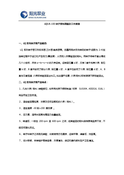
LQ3A-100转子泵构简图及工作原理一、LQ系列转子泵产品概述:LQ系列转子泵又称胶体泵,三叶泵,鞋底泵等。
依靠两同步反向转动的转子(齿数为2-4)在旋转过程中于进口处产生吸力(真空度),从而吸入所要输送的物料。
两转子将转子室分隔成几个小空间,并按a→b→c→d的次序运转。
运转至位置a时,只有I室中充满介质; 到位置b时,B室中封闭了部分介质; 到位置c时,A室中也封闭了介质; 到位置d时,A、B 室与Ⅱ室相通,介质即被输送至出料口。
如此循环往复,介质(物料)即被源源不断地输送出。
二、LQ系列转子泵产品特点:1、凡与介质(物料)接触部位,均采用优质不锈钢制造(材质SUS304、AISI316、316L)完全符合卫生标准。
2、适合输送高粘度、浓度及任何含颗粒的介质(物料)。
3、适合温度-30到+200 摄氏度。
4、压力高,适用长距离与高阻力定量输送。
5、转速低,一般在200 rpm 至600 rpm 之间,经其输送的物料保持原有品质不变,不起任何理化反应。
6、转子和转子之间绝无接触,长期使用亦无磨损,运转平稳,噪音低,效益高。
7、设计新颖、安装维护简单容易,方便清洗,保证机器内部和生产卫生清洁。
转子泵属容积式泵的一种形式,通过转子与泵体间的相对运动来改变工作容积,从而使流体的能量增加。
转子泵又称罗茨泵、胶体泵、高浓浆泵等,它依靠两个同步运动的转子,由一对外置式同步齿轮箱进行传动,转子在传动轴的带动下进行同步反方向旋转,从而构成了较高的真空度和排放压力。
两转子将转子室分隔成几个小空间,并按I-II-III-IV的次序运转。
运转到I位置时,只有进口处充满介质;运转到II位置时,II室中封闭了部分介质;到位置时,III室中也封闭了介质;到位置IV时,进口处和出口室相通,介质即被输送至出物料管道。
按这样的循环往复,介质即被不断的输送出去。
结构特点LQ系列转子泵中凡与输送物料接触的零配件,均采用符合卫生标准的不锈钢材料制作,其密封件均采用无毒橡胶。

转子泵型号前十强十大高粘度转子泵生产厂家排行1.上海沈泉泵阀制造有限公司上海沈泉泵阀制造有限公司是一家专业生产,销售管道泵,排污泵,消防泵,化工泵等给排水设备的厂家,产品涉及工矿企业、农业、城市供水、石油化工、电站、船舶、冶金、高层建筑、消防供水、工业水处理和纯净水、食品、制药、锅炉、空调循环系统等行业领域。
2、广州标宝泵业有限公司广州标宝泵业有限公司是一家机械及行业设备的企业,是经国家相关部门批准注册的企业。
主营各种型号水泵,公司位于中国广东广州市天河区广州市天河区。
广州标宝泵业有限公司本着“客户第一,诚信至上”的原则,与多家企业建立了长期的合作关系。
热诚欢迎各界朋友前来参观、考察、洽谈业务。
3、北京海圣达泵业有限公司北京海圣达泵业有限公司继承北泵六十余载泵类产品研发技术及制造经验,承载着北泵人对国内泵行业的眷恋与期望,于二○○○年十月成立。
目前海圣达泵业是一家集产品开发、试验研究、生产制造、销售、维修、设备成套、培训及技术咨询服务为一体的综合性泵业公司。
4、湖北兴雨泵业股份有限公司湖北兴雨泵业股份有限公司坐落在美丽的江城——湖北武穴。
公司成立于1992年,注册资本6000万元,总资产达1.1亿元,集研发、生产、销售和服务于一体,是华中地区最具竞争力的水泵制造企业之一。
5、江西贝德泵业有限公司江西贝德泵业有限公司前身为上海贝德泵业有限公司永嘉分公司,是一家集设计、开发、制造和销售通用流体设备的股份制企业。
本司与韩国现代泵业、日本寺田株式会社等国外出名的泵阀公司强强技术合作,引进具有国际水平的设计、开发和企业管理模式,并长期聘请国外专家为公司进行技术指导,产品具有国际竞争力。
6、南京环亚制泵有限公司南京环亚制泵有限公司位于南京市世界名曲《茉莉花》的发源地,是一家获得多项专利证书的创新型水泵制造企业,公司消防类产品已获得应急管理部消防产品合格评定中心出具的消防产品认证证书。
公司专业生产深井泵、消防泵、长轴深井泵(轴流深井泵)、深井消防泵(长轴深井消防泵、轴流深井消防泵、立式轴流深井消防泵、电动立式长轴涡轮消防泵),柴油机立式长轴深井消防泵,潜水消防泵、潜水深井泵(井用电泵、井用潜水泵)、潜水排污泵、潜水搅拌机、潜水推进器、潜水曝气机等产品。

三叶转子泵转子间隙调整
三叶转子泵是一种容积式泵,由于其机构简单、使用寿命长和维护简单等优点,已经被广泛运用于各种行业,如生活污水、城市污泥处理、高黏度液体处理,甚至是固液两相流的处理。
转子与泵体之间的间隙对泵的性能有重要影响。
根据研究,当转速为300 r/min~400 r/min 时,转子与泵体间隙从0.5 mm增大到1 mm,转子泵的容积效率分别下降了1.7%、1.8%、3.2%。
这表明减小转子与泵体的间隙可以提高容积效率。
为了深入研究三叶圆弧型凸轮转子泵内部流场的瞬态流动状态,研究者对不同时刻泵内的压强分布和速度分布进行了分析。
此外,利用Fluent数值分析软件,研究了不同转子与泵体间隙下,转子泵内部流场的分布状态,得到了端面间隙对三叶型凸轮转子泵性能的影响规律。

全国最好高粘度凸轮转子泵厂家十大品牌排行榜
①上海沈泉泵业(中国水泵行业后起之秀,不锈钢泵品质好,在化工、市政、建筑、暖通、电厂等领域业绩不错,上海沈泉泵阀制造有限公司)
②连成 (中国驰名商标,上海市名牌产品,在市政、建筑、暖通、电厂等领域业绩不错,上海连成(集团)有限公司)
③凯泉(中国驰名商标,上海市著名商标,在市政、建筑、暖通、电梁禅轿厂等领域业绩不错,上海凯泉泵业(集团)有限公司)
④南方(中国驰名商标,浙江省著名商标,特泵、不锈钢多级泵做的很不错,南方泵业股份有限公司)
⑤东方(上海市著名商标,在建筑领域近两年销量很大,上海东方泵业(集团)有限公司)
⑥博山(驰名商标,山东省著名商标,在钢铁、电力、煤炭等领域业绩不错,山东博泵科技股份有限公司)
⑦新界(中国驰名商标,浙江名牌,农用水泵行业龙头企业,浙江新界泵业股份有限袭伍公司)
⑧熊猫(上海市著名商标,在建筑领域近两年销量很大,上海熊猫机械(集团)有限公司)
⑨双轮(中国驰名商标,山东省著名商标,在油田、石化、矿山、热电等领域业绩不错,上山东双轮股份有限公司)
⑩肯富来(广东省著名商标,广东省名牌,液环真空泵的始创者,广东省佛山水泵厂有限公司)
国产泵业其它品牌:广一、沈阳水泵厂、重庆水泵厂、湘电长沙水泵厂、利欧、化成HCH、凌霄、深蓝、开利、亚梅、安波、兴齐、奥利、石家庄泵业、大耐泵业、三鱼
世界十大水泵品牌
1、美国FLOWSERVE
2、德国威乐
3、美国滨特尔
4、德国凯士比(KSB)
5、日本荏原
6、德国普罗名特
7、美国ITT
8、意大利艾格尔集团
9、丹麦格兰富
10、德国耐驰集团。
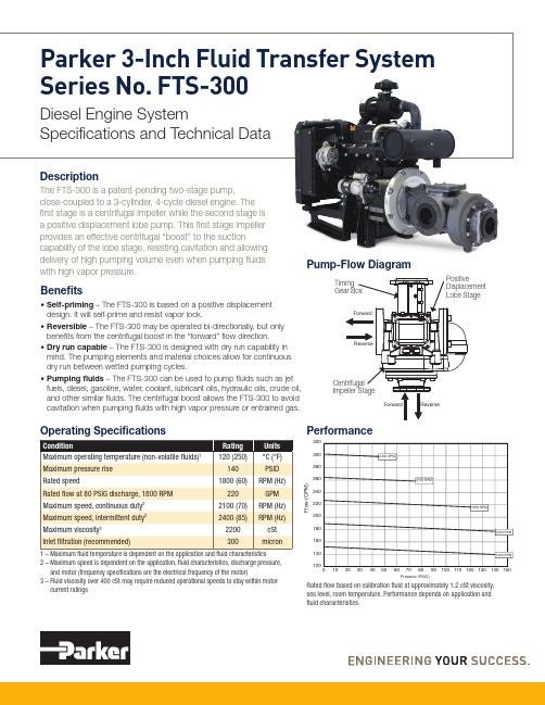
Parker 3-Inch Fluid Transfer System Series No. FTS-300Diesel Engine SystemSpecifications and Technical DataF l o w (G P M )Pressure (PSID)FTS-300 with 24 HP motor, 1.2 cSt calibration fluid -Direction #1 (Forward)DescriptionThe FTS-300 is a patent-pending two-stage pump, close-coupled to a 3-cylinder, 4-cycle diesel engine. The first stage is a centrifugal impeller while the second stage is a positive displacement lobe pump. This first stage impeller provides an effective centrifugal “boost” to the suctioncapability of the lobe stage, resisting cavitation and allowing delivery of high pumping volume even when pumping fluids with high vapor pressure.1 – M aximum fluid temperature is dependent on the application and fluid characteristics2 – M aximum speed is dependent on the application, fluid characteristics, discharge pressure, and motor (frequency specifications are the electrical frequency of the motor)3 – F luid viscosity over 400 cSt may require reduced operational speeds to stay within motor current ratingsOperating SpecificationsBenefits• S elf-priming – The FTS-300 is based on a positive displacement design. It will self-prime and resist vapor lock.• R eversible – The FTS-300 may be operated bi-directionally, but only benefits from the centrifugal boost in the “forward” flow direction.• D ry run capable – The FTS-300 is designed with dry run capability in mind. The pumping elements and material choices allow for continuous dry run between wetted pumping cycles.• P umping fluids – The FTS-300 can be used to pump fluids such as jet fuels, diesel, gasoline, water, coolant, lubricant oils, hydraulic oils, crude oil, and other similar fluids. The centrifugal boost allows the FTS-300 to avoid cavitation when pumping fluids with high vapor pressure or entrained gas.Pump-Flow DiagramPerformance Rated flow based on calibration fluid at approximately 1.2 cSt viscosity, sea level, room temperature. Performance depends on application and fluid characteristics.Weight (Pounds)*Includes other system components.Dimensions (Inches)*Pump Protection OptionsThe FTS-300 may be fitted with accessories from the factory if pump protection devices are desired, or it may be fitted with a block-off plate in the accessory position.• B ypass valve – The FTS-300 Bypass Valve option includes aninternally piloted, field adjustable bypass valve. This valve will begin to open when the set pressure is reached, recirculatingpumped fluid within the pump housing.FTS-D24Y-00 Diesel Engine Specifications FTS-300-DIESEL-CSS REV A MK 3/18© 2018 Parker Hannifin CorporationParker Hannifin Corporation Fluid Transfer Solutions 95 Edgewood AvenueNew Britain, CT 06051, USA phone 1 (844) 695-9590********************/transferpump*Dimensions are for reference only. Diesel engine and pump package shown without skid system. Consult your product owner’s manual for installation rmationsubjecttochangewithoutnotice.Forthemostcurrentinformation,contactParkerApplicationSupportat(844)********************************.Skid System OptionsThe FTS-300 system may be integrated into a turnkey skid package. These skid packages offer a base plate, battery system, fuel tank, and associated engine controls. Contact your Parker Fluid Transfer Solutions sales representative for more information on diesel-drivenpump skid systems from Parker.200220240260280g/kWh 2575100N-m 5005101520kW 10030040050020010001200140016001800200022002400B .S .F .C .B.S.F.C.OutputTorqueExhaust Gas Temp.T o r q u eO u t p u tE x h a u s t G a s T e m p . °CEngine Speed minØ3/4" HOLES & 3" NPTF PORTEngine Performance。

SFA - SANIFLO1 Pumps and lifting stations2For 60 years, the Société Française d’Assainissement[French SanitationCompany] has worked on improving the water treatment processwith Europelec. The Group, which is also the inventor of the famousSANIBROYEUR® SFA, has a worldwide presence (25 subsidaries). Today,it is one of the world leaders in the field of lifting stations.The technological expertise acquired on these products and itsmarket knowledge have enabled the Group to expand its rangeof services: from the SANIBROYEUR® to the floor-standing orunderground lifting station.It now offers a full range of products designed for individual,commercial, industrial and communal use and provides real expertise.> DESIGNAt the company headquarters, located in the heart of Paris, the engineering team designsnew products to meet market expectations. The prototypes are tested by our laboratorieswithin the productions units to ensure their reliability.> FRENCH MANUFACTURINGThe Group has production units in France with ISO 9001 and ISO 14001 certification.This enables product quality to be controlled.> MARKETINGThe Group works closely with its partners by ensuring its teams of experts are available toassist them in the sale of its high-tech products.3FRENCHPRODUCTION SITES60DISTRIBUTORSWORLDWIDE25SUBSIDIARIES60 YEARSOF INNOVATIONI N N O V A T I O N/I N D U S T R I A L E F F I C I E N C Y/C U S T O M E R S E R V I C E SFA, WORLD LEADERIN SANITARY FACILITIESMADE IN FRANCES E R V I C E S34HELP TO CHOOSE YOURPUMPING STATIONNumber of residences Flow rate1 residence (1 to 3 people) 2.5 m3/hUp to 2 residences (4 to 6 people) 5 m3/hUp to 4 residences (7 to 9 people) 10 m3/hUp to 6 residences (10 to 12 people) 15 m3/hEstimated flow rateO n the basis of 1 residencecomprising: 1 WC, 1 bath,1 shower, 1 basin, 1 sink,1 washing machine, 1 dishwasherThe flow rate is the amount of water to beevacuated according to the type and numberof devices connected to the pumping station.The flow rate measures a volume per unitof time. It is expressed in cubic metres perhour (m3/h) or litres per second (L/s).DETERMINETHE REQUIRED FLOW RATE1The value obtained in this table must be multiplied bythe total length of the discharge pipe to obtain thetotal loss of loads.These values have been increased to accountfor the check valves, elbows...TDH is the pressure the pump must providebetween the suction point and the dischargepoint.TDH = Geo H + H vGeo H = geometric heightThis is the height of the discharge in meters.H v = Total friction losses in the discharge pipe(expressed in metres of water column).There are 2 types of friction loss:· r egular friction losses (or linear) : these result fromthe friction of the fluid against the walls of thedischarge pipe· s ingular friction losses : these result frompipework fittings (elbow, check valves, etc…)These have to be added to the geometric height todetermine the total dynamic head.Flowratein m3/hPipework of PVC pressure pipesØ INT / EXT Ø40/49Ø INT / EXT Ø50/60Ø INT / EXT Ø80/90Ø INT / EXT Ø102/1142.50.011---50.0380.0090.001-60.0550.0130.002-70.0670.0170.003-80.0780.0200.0030.00190.0990.0250.0040.002100.1200.0300.0050.002120.1600.0450.0060.002150.2500.0650.0090.00320-0.1000.0140.00525-0.1600.0200.00830-0.230.0300.01040-0.350.0450.017CALCULATE THE TOTALDYNAMIC HEAD (TDH)2Table of friction lossesTwo residences are connected to a lifting station. The station must discharge wastewater at a height of 4 m over a length of 10 m in 50 mm PVC outside.• Geometric height: 4 m.• F riction losses: for 2 residences,we estimate the flow rate at peak times to be 5 m 3/h.According to the friction loss table, the height is : 0.038 x 10 = 0.38 mt he total dynamic head will be : 4 m + 0.38 m = 4.38 mT he station has the following criteria : TDH = 4.38 m and flow rate rate = 5 m 3/hOur client wants to install an underground pumping station in his garden.The SANIFOS ® range corresponds to his needs.Its installation requirements correspond with a 250 litre tank.Analysis of the pump curve for the SANIFOS ® confirms to us that the SANIFOS ® 250 meets the needs of the installation.CASE STUDYFIND OUT MORE INFORMATIONABOUT THE PUMPING STATION SIZES IN OUR SFAPUMPING STATION INSTALLATION GUIDE.Once the total dynamichead and the peak flow rate have been established, the pump's typical curve can determine its suitability for the requirements.The volume of the tank can then be decided in accordance withthe specific constraints of each installation.56FLOOR-STANDINGLIFTING STATIONSUNDERGROUNDLIFTING STATIONS TYPICALAPPLICATIONSFOR LIFTING STATIONSCOMMUNALUSESMALL COMMUNAL GROUP,PROFESSIONAL BUILDINGSCUBIC®2 XL FOS®500GREYAND BLACK WATERGREYAND BLACK WATERINDIVIDUALUSESMALL HOUSES,DETACHED HOUSESCUBIC®1WP FOS®250FOS®110COMMERCIALUSESHOPS,PUBLIC PLACESGREYAND BLACK WATERCUBIC®2 CLASSICCUBIC®2 PROCUBIC®2 XLFOS®250FOS®500FOS®110PUMPING STATIONUNDERGROUNDPUMPING STATION• SAVING SPACE IN YOUR HOME• COMPLETELY DISCREET OPERATION• LOW INSTALLATION COST• EASY ACCESS FOR MAINTENANCEF L O O R -S T A N D I NG R A N G EPUMPS BENEFITSSANICUBIC ® 1 WPSANICUBIC ® 2 CLASSIC /SANICUBIC ® 2 PROSANICUBIC ® 2 XL SINGLE-PHASE / SANICUBIC ® 2 XL THREE-PHASEU N D E R G R O U N D R A N G EINSTALLATION ADVICEFOR UNDERGROUND STATIONSSANIFOS ® BENEFITS SANIFOS ®110SANIFOS ®250SANIFOS ® 500 SINGLE-PHASE /SANIFOS ®500 THREE-PHASES U B M E R S I B L E R A N G ESANIPUMP ®A C C E S S O R I E SSTOP VALVES / EXTENSIONSC O N T A C T S082627281012161814202224Saniflo offers a wide range of lifting stations to meeta single or three-phase version, with or without grinding system.P R O D U C T S8SFA PUMPSSFA GRINDING> THE PUMPSThe pump is the main element of the pumping station.It pumps away waste water from an installation.SFA is always innovating and improving the performance andreliability of its pumps.The safety of the pumps are guaranteed by extensive testingduring the design phase in our French factories: two 100%electric tests, one 100% watertightness test and finally anoperational test.OUR DIFFERENT SYSTEMS:CUBIC® 2 XL CUBIC® 1WP and 2FOS®VORTEX KX V6Grinding BLADE ProX K2 (Impeller not shown)9THE SFA PUMPS FROM THESANICUBIC ®* AND SANIFOS ®RANGES INTEGRATE THE SFA GRINDING SYSTEM... KNOWN AND RECOGNISED FOR MANY YEARS.The ProX K2 grinding blade avoids the body of the pump becoming clogged for optimum operation of the installation.The design of the ProX K2 grinding blade avoids cloggingbetween the fixed plate and the moving blade for completely reliable operation.* Except for SANICUBIC 2 XLThe SFA grinding blade also prevents the clogging of pipes and makesevacuate in small pipeworks possible.ANTI- CLOGGINGFACILITATED DISCHARGESAFETYClogged pump,without grinding systemHandle for easy liftingDouble motor chamber for bettermechanical strengthOil lubricated and cooledDischarge via DN 40Base plateStainless steel shaft Thermal protection Easy access to the condenser SFA grindingsystemPUMPImpeller Clogged pipesand non-clogged pipes thanks tothe grinding system10HIGH-PERFORMANCEOPERATIONS FA grinding systemFlow rate : 13 m3/ hD ischarge height of 13 m (Q = 0l / min)SAFEOPERATIONA udible and visual alarm box3 dip tubes : 2 forengaging the motorand 1 for the alarmI P68 reinforced watertightnessand remote controlEASY INSTALLATIONAND MAINTENANCECompact floor-standing unit4 inlets availableDischarge via DN 40 ( Ø ext. 50 mm )13 mCUBIC®1WPFLOOR-STANDING PUMPING STATIONGREY WATER +BLACK WATERWC, bathroom, kitchen and laundryINDIVIDUALUSESFA grindingsystem(see pg.08 )11TE C H N I C A L C H A R A C T E R I S T I C S :Remote wired audible and visual alarm (5 m of cable)SANICUBIC ® 1 WPF L O O R -S T A N D I NG R A N G E T A N KTank volume32 LDischarge pipework DN 40 (Ext. Ø 50 mm)Inlet pipeworks• 1 inlet ( Ø• 3 inlets ( ØVentilationØ ext. 50 mmIncoming waste water max. temperature 70°C intermittently ( Built-in check valve Material Polypropylene 20 % fibreglass O R M A N C E SMax. flow rate13 m 3/h Ø 100Ø 100Ø 50Ø 50Ø 50Ø 50570 mm460 mm 426 mm 439 m m365mm Ø ext. 100/110INLETSØ ext. 40/50Ø ext. 100/1101213 mFLOOR-STANDING PUMPING STATIONCUBIC®2 PROFLOOR-STANDING PUMPING STATIONHIGH-PERFORMANCEOPERATIONS FA grinding systemFlow rate: 13 m3/ hD ischarge height of 13 m (Q=0 l/min)2 motors for intensive useSAFEOPERATION2 motors with duty standby systemR emote audible and visual alarm box(wireless on the PRO version)3 dip tubes: 2 for engaging the motorand 1 for the alarmI P68 waterproofEASY INSTALLATIONAND MAINTENANCEC ompact floor-standing unit5 inlets availableD ischarge via DN 40 ( Ø ext. 50 mm )GREY WATER +BLACK WATERsmall buildings or shops.CUBIC®2 CLASSICCOMMERCIALUSESFA grindingsystem(see pg.08 )13HF remote alarm boxF L O O R -S T A N D I NG R A N G E T E CH NI C A L C H A R A C T E R I S T KTank volumeDischarge pipework Inlet pipeworksRemote control box (4 m of cable)ø 100ø 100ø 100ø 100ø 50ø 50ø 50688 mm 597 mm ø 100ø 100348 m m515 mm 380 m m 440 m mINLETSØ ext. 40/50Ø ext. 100/110INLETS Ø ext. 40/50Ø ext. 100/110INLETSØ ext. 40/50Ø ext. 100/110SANICUBIC ® 2 CLASSICSANICUBIC ® 2 PRO14HIGH-PERFORMANCEOPERATIONV ORTEX system(clearance : 50 mm)Flow rate : 55 m3/hM aximum vertical discharge pipe(Q=0 l/min) : 17 mEASE OF INSTALLATIONAND MAINTENANCEFloor-standing product5 inlets availableAvailable in single and three-phase versionsD irect and secure access to the 2 motorsand level sensors without drainageRELIABILITY3 dip tubesI P68 waterproofR emote control and alarm boxes17 mFLOOR-STANDING PUMPING STATIONAvailable with single and three-phase motorsGREY WATER+BLACK WATERWC, bathroom, kitchen and laundryCUBIC®2 XLCOMMERCIAL&COMMUNAL USESN E WA V A I LA B L E INT H R E E-P H A SE15713 mm 142 mm171 mm751 m m189 m m 913 mm404437INLETS Ø ext. 40/50Ø ext. 100/110INLETSØ ext. 40/50Ø ext. 100/110INLETS Ø ext. 40/50Ø ext. 100/110INLETS Ø ext. 40/50Ø ext. 100/110DISCHARGE DN 100 (Ø ext. 110)VENTILATION Ø ext. 75 INLET Ø ext. 40/50T E C H N I C A L C H A R A C T E R I S T I C S :T A N KTank volume120 LDischarge pipework DN 100 (Ext. Ø 100 mm)Inlet pipeworks• 1 inlet ( Ø• 4 inlets ( VentilationØ ext. 75 mmIncoming waste water max. temperature 70°C intermittently ( Built-in check valve MaterialPolypropylene 20 % fibreglass P U M PPump system Vortex Clearance50 mm Activation system Dip tube Protection index IP68Electric class IRemote wired audible and visual alarm box (5 m of cable)Remote control box (4 m of cable) withSANICUBIC ® 2 XLsingle-phase127 mm 126 m m200 mm457 mm206 mm 127 mm118 m m207 m mSMART Box with SANICUBIC ® 2 XLthree-phaseSANIFOS®THE GROUND TYPE *SANIFOS ®LIFTING STATIONS CAN ALSO BE INSTALLEDINSIDE THE HOME,STANDING ON THE FLOOR.* F or accurate technical information, please refer to the installation instructions and professional standards or seek advice from our technical service : *************Invert levelConcrete ballastGravel and sand Arrivalof effluentsDischarge1Before the installation of an underground pumping station, it is imperative to be fully aware of the soil type.16StandardsOur appliances comply with standardsEN12050-1 for all-water lifting stations and must be installed in accordance with the recommendations of standard EN12056-4.DURING SANIFOS ®UNDERGROUND PUMPING STATION INSTALLATION, DIFFERENT PARAMETERS MUST BE CONSIDERED AND FOLLOWED.WHERE IS YOUR PUMPING STATION BEING INSTALLED?WHY DOES YOURPUMPING STATION NEED GOOD VENTILATION?Ventilation must be installed in the upper part of the pumping station to: • e vacuate the gases that form inside the tanks and prevent any risk of explosion • a void the station from losing pressureTo do this, lifting stations have two ventilation outlets.SANIFOS ® lifting stations have an invert level of 311 mm ( and 611 mm with the extension), enabling them to be installed at various distances from the house.231718SANIFOS ®by stainless steel screwsfor maximum safety levelsRotational-moulded polyethylenehigh-density tank with high mechanicalresistance, anti-odour, resistantto chemical attacks and UV raysSelf-cleaning tank floor(on SANIFOS® 110 and SANIFOS® 250)Thermal motor protection… RELIABILITYExterior orinterior installations30 cm extension available as anaccessory (inlet depth of 611 mm )2 ventilation openings6 inlets for multiple pipework40/50/100/110/125… FLEXIBILITY19Automatic pumping operation New motor designfor improved mechanical and thermal resistanceEnergy-saving and reduced useof the motors thanks to a high useful volume (only on SANIFOS ® 500)SFA grinding system… PERFORMANCEStation delivered fitted with: PVC hydraulic pressure connectors pre-assembled inside the tank with stop valves, check valves, alarm and low/high detection floats Fixing pointsInvert level of 311 mmCable gland for motor cables and level sensors Large tank opening for easy maintenance Cable supplied for the lifting of the pumpsof the power supply without having to pull out the electricity cable… E ASY INSTALLATION AND MAINTENANCE20HIGH-PERFORMANCEOPERATIONSFA grinding systemMaximum vertical discharge ( Q =0 l/min): 14 m Flow rate : 11 m 3/h 110 litre tankEASY INSTALLATION AND MAINTENANCEStation delivered fitted with preassembled hydraulics Automatic pump operationScrew cap for easy service accessUNDERGROUND LIFTING STATION / 1 PUMPFOS ®110GREY WATER + BLACK WATERWC, bathroom, kitchen and laundry14 mSFA grinding system (see pg.08 )Benefits of the SANIFOS ®(see pg.18 )INDIVIDUAL &COMMERCIAL USESINLETSØ ext. 40/50Ø ext. 100/110/125Ø ext. 100/110/125INLETØ ext. 40/50DISCHARGE DN 40Ventilation Ø752 i n l e t s Ø 502 i n l e t s Ø 100d i s c h a r ge Ø40 e x t .5 2 fixing points482 m m515 m m69 m m325 m m300 m m587 m m90 m m 180 m m277 m m674 mm 86 mm696 mm 180 m m 60 m m94 m m316 m m166 m m22HIGH-PERFORMANCEOPERATIONSFA grinding systemMaximum vertical discharge (Q=0 l/min) : 14 mFlow rate : 11 m3/h250 litre tankEASY INSTALLATIONAND MAINTENANCES tation delivered fitted with pre-assembled hydraulics,stop valve and check valveAutomatic pumping operationD esigned to make maintenance easierwith stop valve and rope included as standard UNDERGROUND LIFTING STATION / 1 PUMPFOS®250GREY WATER +BLACK WATERWC, bathroom, kitchen and laundry14 mINDIVIDUAL &COMMERCIAL USESSFA grindingsystem(see pg.08 )Benefits ofthe SANIFOS®(see pg.18 )discharge height (m)21PUMP GRAPHT A N KTank volume 250 LMaterialPolyethylene high-densityDischarge pipeworkDN 40 (Ext. Ø 50 mm)Inlet pipeworks6 inlets( Ø ext. 40/50/100/ 110/125 mm)Ventilation 2 x Ø ext. 75 mm Incoming waste water max. temperature 70°C intermittently ( m ax. 5 mins)Weight(tank + hydraulic only)25 kgBuilt-in check valve + stop valve P E R F O R M A N C E SMax. flow rate11 m 3/hMax. height(Q=0 l/min)14 mIncoming waterflow rate height 311 mmP U M P Pump system Grinder Activation system Float ON/OFF level 400/100 mm Power 220-240 V/50 Hz Motor consumption 1 500 W Max. intensity 6 A Weight (pump only)13 kg Protection index IP68Electric class I Thermal overload protectionINLETS Ø ext. 40/50Ø ext. 100/110/125Ø ext. 40/50Ø ext. 100/110/125INLETS Ø ext. 40/50Ø ext. 100/110/125Ø ext. 40/50Ø ext. 100/110/125DISCHARGE DN40d i s c h a r ge Ø403 fixing points2 V e nt i l a t i on i nl e ts Ø75Ø 550Ø7406 i n l e t s Ø 506 i n l e t s Ø 100710 m m555 m m530 m m176 m m924 m m280 m m 130 mm 982 mm30 m m150 m m 150 m m886 m me x t .5024HIGH-PERFORMANCEOPERATIONS FA grinding system2 motors for more intensive useM aximum vertical discharge ( Q=0 l/min) : 21 mFlow rate : 15.5 m3/h500 litre tankEASY INSTALLATIONAND MAINTENANCES tation delivered fitted with pre-assembled hydraulics,stop valves and check valvesS MART monitoring systemof the station with remote alarm unitD esigned to make maintenance easierwith stop valves and ropes included as standard UNDERGROUND LIFTING STATION / 2 PUMPSFOS®500GREY WATER +BLACK WATERWC, bathroom, kitchen and laundry21 mCOMMUNAL &COMMERCIAL USESSFA grindingsystem(see pg.08 )Benefits ofthe SANIFOS®(see pg.18 )Available with single and three-phase motors• Max. height (Q=0 l/min) : 21 m • Flow rate : 15.5 m 3/h• Engine power : 230-400V / 50Hz• Maximum current consumption : 2 x 4.75 A • Consumption : 2600 WS A N I F O S 500 T H R E E -P H A S E• Max. height (Q=0 l/min) : 14 m • Flow rate : 11 m 3/h• Motor power : 220/240V / 50 Hz• Maximum current consumption : 2 x 6 A • Consumption : 1500 W S A N I F O S 500 S I N G L E P H A S ESMART MONITORING SYSTEM OF THE PUMPING STATION WITH REMOTE ALARM UNIT• I nterface with text, date and time • L ogbook ( p ump operating times, fault list etc. )• A s done previously • P ower disconnector swich for increased safetyPower disconnector switchInterface with text ReturnMenu browserStatus indicatorsActivation/ deactivation of the pumpsManual overrideMenu accessHF remote alarm boxT A N KTank volume 500 LMaterialPolyethylene high-density Discharge pipework DN 40 (Ext. Ø 50 mm)Inlet pipeworks6 inlets ( Ø ext. 40/50/100/110/125 mm)Ventilation 2 x Ø ext. 75 mm Incoming waste watermax. temperature 70°C intermittently ( m ax. 5 mins)Weight(tank + hydraulic only)63 kgBuilt-in check valve + stop valve Incoming waterflow rate height 311 mmP U M PPump system Grinder Activation system Float ON/OFF level 500/135 mm Weight (pump only) 2 x13 kg Protection index IP68Electric class I Thermal overload protectionINLETS Ø ext. 40/50Ø ext. 100/110/125INLETS Ø ext. 40/50Ø ext. 100/110/125INLETS Ø ext. 40/50Ø ext. 100/110/125Ø ext. 100/110/125Ø ext. 100/110/125DISCHARGE DN40e x t .50d i s c h a r ge Ø40 3 fixing points2 V e nt i l a t i on in l et sØ 706 i n l e t s Ø 506 i n l e t s Ø 10026S U B M E R S I B L E P U M PHIGH-PERFORMANCEOPERATIONS FA grinding systemA utonomous pump operationFlow rate : 11 m3/hM aximum vertical discharge (Q=0 l/min) : 14 mON/OFF level : 400/100 mmPUMP®GRINDING SUBMERSIBLE PUMP14 mGREY WATER +BLACK WATERWC, bathroom, kitchen and laundryINDIVIDUALUSEdischarge height (m)flow rate (m/h)211815129630 2 4 6 8 10 12 14 16 18 20PUMP GRAPH382265G 1-1/4For pipework 110 or 100 For pipe60Y E A R S O F I N N O V A T I O NSFA / SANIFLOSFA - SANIFLO41 bis Avenue Bosquet75007 Paris - France*************。
High Pressure, High Performance Triple Vane Pump VMQ3453525SS eries — 32 DesignIncluded in Single STD Seal Kit 02-346523 or Viton Seal Kit 02-346532.Included in Doublt STD Seal Kit 02-346531 or Viton Seal Kit 02-346533.*With double and triple pumps, the orientation of the kits is such that the kit rotation is a reverse of the pump rotation. See tables X1 and X2 for the correct kit rotation relative to the pump rotation.OUTLET BODYFlange Single Shaft Seal Double Shaft SealMounting Inch Port Metric Port Inch Port Metric Port Style Threads Threads Threads ThreadsSAE B998754998748998755998749ISO 100—998756—998757TABLE 1TABLE 2MODEL CODE30TH DESIGN 31ST & 32ND KEY SHAFT DESIGN SHAFT3453525VMQ–***–***–*–*–019970924993377-0019285423453525VMQ–***–***–*–*–029970804993376-001—3453525VMQ–***–***–*–*–039970934993378-0019285473453525VMQ–***–***–*–*–059970944993379-0019285433453525VMQ–***–***–*–*–069970954993380-001—3453525VMQ–***–***–*–*–099970964993381-001—Cartridge Kit Rotation for Left Hand Rotation PumpR= Right Hand RotationL=Left Hand RotationPUMP SHAFT END CENTERCOVER ENDROTATIONKIT ROTATIONKIT ROTATIONKIT ROTATIONTriple (L)(L)(R)(R)*Notes:- A left hand rotation pump has the shaft turning counterclockwisewhen viewed from the input shaft end- When ordering a left hand rotation kit, the part number will have a su x of ‘-L’TABLE X2Cartridge Kit Rotation for Right Hand Rotation PumpR= Right Hand RotationL=Left Hand RotationPUMP SHAFT END CENTER COVER ENDROTATIONKIT ROTATIONKIT ROTATIONKIT ROTATIONTriple (R)(R)(L)(L)*Notes:- A right hand rotation pump has the shaft turning clockwise whenviewed from the input shaft end- When ordering a right hand rotation kit, the part number will not have a su x.TABLE X1TABLE 3MODEL CODE*•CARTRIDGE *•CARTRIDGEENDRT I KOVC)ET I V(ONB(T I KUN)N-AVMQ3453525S***-***-01002-46557402-465569VMQ3453525S***-***-01602-46557502-465570VMQ3453525S***-***-02002-46557602-465571VMQ3453525S***-***-02502-46557802-465572VMQ3453525S***-***-03202-46557702-465573VMQ3453525S***-***-04002-34897402-348981VMQ3453525S***-***-04502-34897502-348982VMQ3453525S***-***-05002-34897602-348983VMQ3453525S***-***-06302-34897702-348984VMQ3453525S***-***-07102-34897802-348985VMQ3453525S***-***-08002-34897902-348986VMQ3453525S***-***-09002-34898002-348987TABLE 4MODEL CODE*•CARTRIDGE *•CARTRIDGECENTER SECTION KIT (BUNA-N)KIT (VITON)VMQ3453525S***-090-***02-46562102-465622VMQ3453525S***-100-***02-46562302-465624VMQ3453525S***-112-***02-46562502-465626VMQ3453525S***-125-***02-46562702-465628VMQ3453525S***-135-***02-46562902-465630VMQ3453525S***-140-***02-46563102-465632VMQ3453525S***-158-***02-46563302-465634TABLE 5MODEL CODE*•CARTRIDGE *•CARTRIDGET I KNDET FHAS)NB(NT I V(OU)N-AT I KVMQ3453525-140-***-***02-34697002-346971VMQ3453525-160-***-***02-34696802-346969VMQ3453525-180-***-***02-34696602-346967VMQ3453525-195-***-***02-34696402-346965VMQ3453525-215-***-***02-34696202-346963Model CodeVMQ3 ** ** 25 *** *** *** * ** * * * * * * * 00 * 0 321 2 3 45 67 811 12 132021 22242526272829323334 359 1014 15 1617 18 192330 31* Verify shaft torque ratings meet or exceed input torque requirementsSeries designation VMQ3 – Vane pump triple series Frame size (front section)45–140-215 cm 3/r (8.54-13.12 in3/r)Frame size(middle section)35–90-158 cm 3/r (5.49-9.64 in3/r)Frame size (rear section)25–10-90 cm 3/r (0.62-5.49 in3/r)Displacement(front section)Frame size 45140–140 cm3/r (8.54 in 3/r)160–160 cm3/r (9.76 in 3/r)180–180 cm3/r (10.98 in 3/r)195–195 cm 3/r (11.89 in 3/r)215–215 cm 3/r (13.12 in 3/r)Displacement(middle section)Frame size 35090–90 cm3/r (5.49 in 3/r)100–100 cm 3/r (6.10 in 3/r)112–112 cm 3/r (6.83 in 3/r)125–125 cm3/r (7.63 in 3/r)135–135 cm3/r (8.24 in 3/r)140–140 cm 3/r (8.54 in 3/r)158–158 cm 3/r (9.64 in3/r)Displacement(rear section)Frame size 25010–10 cm3/r (0.62 in 3/r)016–16 cm3/r (0.98 in 3/r)020–20 cm3/r (1.23 in 3/r)025–25 cm 3/r (1.58 in 3/r)032–32 cm 3/r (1.96 in 3/r)040–40 cm3/r (2.44 in 3/r)045–45 cm3/r (2.75 in 3/r)050–50 cm 3/r (3.05 in 3/r)063–63 cm 3/r (3.84 in 3/r)071–71 cm3/r (4.33 in 3/r)080–80 cm3/r (4.88 in 3/r)090–90 cm 3/r (5.49 in 3/r)Front ange mounting styleA–SAE C 2-boltSAE J744 127-2127,00 (5.000) x 12,4 (0.49) pilot17,6 (0.69) slots on 181,0 (7.13) bolt circle B –ISO 3019/2 125A2HW 2-bolt125,00 (4.921) x 9,2 (0.36) pilot18,1 (0.71) slots on 180,0 (7.09) bolt circleInput shaft type*01–SAE J744 keyed Frame size 45: 38,10 (1.500)02–SAE J744 splined Frame size 45: C-C 03–ISO 3019/2 keyed Frame size 45: 40,00 (1.575)05–SAE J744 keyed Frame size 45: 44,45 (1.750)06–SAE J744 splined Frame size 45: DPort type A–Inlet: SAE J518 4-boltangeFront outlet: SAE J518 4-bolt angeMiddle outlet: SAE J5184-bolt angeRear outlet: SAE J518 4-bolt angeB –Inlet: ISO 6162 4-bolt angeFront outlet: ISO 6162 4-bolt angeMiddle outlet: ISO 6162 4-bolt angeRear outlet: ISO 6162 4-bolt angeFront outlet port positionViewed from cover end of pumpA –Opposite inlet portB –90°CCW to inlet portC –In-line with inlet portD –90°CW to inlet portMiddle outlet port positionViewed from cover end of pumpA –Opposite inlet portB –90°CCW to inlet portC –In-line with inlet portD –90°CW to inlet portRear outlet port positionViewed from cover end of pump453525 units E –Opposite inlet port F –90°CCW to inlet port G –In-line with inlet port H –90°CW to inlet portShaft sealA–Single, primary B–Double, secondary (spring side out)Recommended for wet mount applicationsSeal typeN –Buna N V –VitonW –Buna N with Viton shaft seal(s)Shaft rotationViewed from shaft end of pumpL –Left hand (CCW)R–Right hand (CW)Special features00–NonePaint0–None A –BlueCustomer identi cation–NoneDesign code32–32 designInstallation dimensions remain unchanged for design numbers 31 to 39 inclusive.34 35333230 312928272625242321 222017 18 1914 15 1611 12 139 107 85 61 2 3 4Danfoss Power Solutions is a global manufacturer and supplier of high-quality hydraulic and electric components. We specialize in providing state-of-the-art technology and solutions that excel in the harsh operating conditions of the mobile off-highway market as well as the marine sector. Building on our extensive applications expertise, we work closely with you to ensure exceptional performance for a broad range of applications. We help you and other customers around the world speed up system development, reduce costs and bring vehicles and vessels to market faster.Danfoss Power Solutions – your strongest partner in mobile hydraulics and mobile electrification.Go to for further product information.We offer you expert worldwide support for ensuring the best possible solutions foroutstanding performance. And with an extensive network of Global Service Partners, we also provide you with comprehensive global service for all of our components.Local address:DanfossPower Solutions GmbH & Co. OHG Krokamp 35D-24539 Neumünster, Germany Phone: +49 4321 871 0DanfossPower Solutions ApS Nordborgvej 81DK-6430 Nordborg, Denmark Phone: +45 7488 2222DanfossPower Solutions (US) Company 2800 East 13th Street Ames, IA 50010, USA Phone: +1 515 239 6000DanfossPower Solutions Trading (Shanghai) Co., Ltd.Building #22, No. 1000 Jin Hai Rd Jin Qiao, Pudong New District Shanghai, China 201206Phone: +86 21 2080 6201Danfoss can accept no responsibility for possible errors in catalogues, brochures and other printed material. Danfoss reserves the right to alter its products without notice. This also applies to products already on order provided that such alterations can be made without subsequent changes being necessary in specifications already agreed.All trademarks in this material are property of the respective companies. Danfoss and the Danfoss logotype are trademarks of Danfoss A/S. All rights reserved.Products we offer:•Cartridge valves •DCV directional control valves•Electric converters •Electric machines •Electric motors •Gear motors •Gear pumps •Hydraulic integrated circuits (HICs)•Hydrostatic motors •Hydrostatic pumps •Orbital motors •PLUS+1® controllers •PLUS+1® displays •PLUS+1® joysticks and pedals•PLUS+1® operator interfaces•PLUS+1® sensors •PLUS+1® software •PLUS+1® software services,support and training •Position controls and sensors•PVG proportional valves •Steering components and systems •TelematicsHydro-GearDaikin-Sauer-Danfoss。
转子泵是容积式泵的一种形式。
是由旋转的转子与静止的泵体组成,它没有吸入、排出阀,通过转子与泵体间的相对运动来改变工作容积,并借旋转转子的挤压作用排出液体,同时在另一侧留出空间,形成低压,使液体连续地吸入。
转子泵按其结构和原理,可分为齿轮泵、螺杆泵、旋转活塞泵(凸轮泵、罗茨泵)、挠性叶轮泵、滑片泵、软管泵等。
转子泵是一种旋转的容积式泵,具有正排量性质,其流量不随背压变化而变化。
国内转子泵十大品牌排行榜高粘度转子泵生产厂家排名前十名1. 上海沈泉泵阀制造有限公司优秀水泵制造商-上海沈泉泵阀制造有限公司是一家专业生产,销售管道泵,排污泵,消防泵,化工泵等给排水设备的厂家,产品涉及工矿企业、农业、城市供水、石油化工、电站、船舶、冶金、高层建筑、消防供水、工业水处理和纯净水、食品、制药、锅炉、空调循环系统等行业领域。
上海沈泉泵阀制造有限公司是集研究、开发、生产、销售和服务为一体的大型泵阀生产企业。
产品涉及工矿企业、农业、城市供水、石油化工、电站、船舶、冶金、高层建筑、消防供水、工业水处理和纯净水、食品、制药、锅炉、空调循环系统等行业领域。
2. 安徽国泰泵科技有限公司安徽国泰泵科技有限公司是集设计、研发、生产、销售工业泵及成套节能设备和泵用控制设备于一体的大型综合性泵业厂家。
公司始终以满足客户用泵需求为本,为客户创造价值。
制造精品、技术响应迅速、服务团队热忱,为油脂、冶金矿产、石油化工、水利市政、电力环保、煤炭消防、制药、市政、农业灌溉等行业客户提供性价比优的服务。
3. 秦平机械(上海)有限公司秦平机械(上海)有限公司是专业的转子泵生产厂家, 公司对凸轮转子泵进行了长期的研究, 产品采用模块化设计与整体铸造加工。
生产过程中注重新材料与新工艺的使用, 同时重视对技术与设备的投入, 进口德马吉5轴联动的数控车床和马扎克四轴联动的加工中心。
这些高精度加工设备的购置与使用,使我们的产品在品质上足以与国外同类产品媲美, 奠定了可靠的质量基础. 公司拥有专业的团队,对您的各种需求都能提供更好的选择。
V5658120E,CE系列端吸离心泵用户指导手册E&CE Pumps ManualInstallation Operating Maintenance请在安装、操作、使用和维修本设备之前,必须阅读本指导手册。
—安装 —操作 —维护E,CE系列端吸离心泵安装、操作及维护手册目录1概要 (5)1.1注意事项 (5)1.2 免责声明 (5)1.3保证 (5)1.4 安全 (5)2运输和存放 (5)2.1货物接收和拆包 (5)2.2吊运 (6)2.3 储存 (6)3产品介绍 (7)3.1型号说明 (7)3.2结构 (7)3.3性能 (7)4 安装 (7)4.1 安装位置 (7)4.2 零件装配 (7)4.3灌浆 (8)4.4联轴器对中 (8)4.4.1检查和调整对中的要点 (8)4.4.2对中测量方法 (8)4.5管道连接 (9)4.5.1吸入管道 (9)4.5.2排出管道 (9)4.5.3辅助管道 (9)4.5.4 最终检查 (10)4.6 最终轴对准检查 (10)4.7 电气连接 (10)5 试车、启动、运行和停机 (10)5.1 试车前步骤 (10)5.1.1 润滑 (10)5.1.2旋转方向 (10)5.2启动泵 (10)5.3运行泵 (11)5.4 停止和关机 (11)6 维护及维修 (11)6.1概述 (11)6.2 检查计划 (11)6.2.1 例行检查(每日/每周) (11)6.2.2 定期检查(每6个月) (12)6.3 备件 (12)6.3.1 备件订购 (12)6.3.2 备件的存放 (12)6.4 推荐的备件 (12)6.5 所需工具 (12)6.6 紧固件扭矩 (13)6.7 拆卸 (13)6.8 装配 (13)7故障原因及纠正措施 (14)8零件清单及图纸 (15)8.1装配结构图及零件清单 (15)8.2爆炸零件图及零件清单 (16)9增补信息 (17)E,CE系列端吸离心泵安装、操作及维护手册1概要该指导手册必须存放在产品的运行位置附近,或者与产品存放在一起。
HigH Viscosity Drum PumPsOMEGA® FPUD500 Series highviscosity drum pumps can empty awide variety of containers in variousapplications. The pump tube and motor are constructed modularly and supplied separately for maximum flexibility.Motor types available are 115 or 230 Vac, continuous duty, totally-enclosed fan-cooled (TEFC); and air driven. All motors listed as115 Vac can be rewired for 230 Vac operation; all motors listed for230 Vac can be rewired for 208or 460 Vac operation. The Hz rating and number of phases CANNOT be changed in the field. All Vac powered units include a 3.6 m (12'), three-wire cord and built-in ON/OFF switch.The FPUD531 air motor has a¹⁄₄" female end fitting, while the FPUD532 and FPUD533 air mo-tors have a ¹⁄₂" female end fitting for hooking up to a customer-supplied air hose, and includes a regulator valve and muffler. An optional air lubricator/filter assembly is also available if your air source is not filtered and lubricated.When pumping flammable or combustible materials, or working in explosive environments, use an air motor with a stainless steel tube and FPUD5-SK static protection kit.FPUD531 air motor, shown smaller than actual sIze.FPUD500Pump MotorsU P ump Tube and Motor Supplied Separately forMaximum FlexibilityU316 SS or SanitaryPolished 316 SS PumpTubes AvailableU T EFC or Air Driven Motors U F or Fluids up to15,000 cps Viscosity and1.8 Specific GravityLinclude power cord.Ordering Examples: FPUD532, air motor, FPUD5-SK, anti-static kit,and FPUD5-S40, pump tube.FPUD511, 115 Vac motor, FPUD5-S40, 316 SS tube.Too heavy for UPS shipment; use other motor freight.**CE certified FPUD5-S40,316 SS pump tube shownsmaller than actual size.FPUD5-SS FPUD5-SDA。
Fristam FL3
Fristam Pumps UK Limited Partnership Unit 11 APEX Business Park Diplocks Way, Hailsham East Sussex BN27 3JU Great Britain Tel +44 (0)1323 849 849Fax +44 (0)1323 849 438E-Mail sales @ For international contact
information, please
visit www.fristam.de .
Fristam rotary lobe pumps FL3
BENEFITS • Improved performance and reduced associated costs • Low pulsation • Product and CIP operation
using only one pump SPECIFICATIONS FRISTAM FL3 100L *
Design Rotary lobe pump with counter-rotating
rotors designed to handle viscous and non-
viscous products.
Construction Special three-wing design helical rotors allow
safe and gentle product handling and virtu-
ally eliminate pulsation. Consequently the
pump operates at faster speeds and reduced
noise.
Advantages Smooth operation. Higher flow rates achie-
ved with the same pump size. Dual duty,
using only one pump for product and CIP
operation. Gentle product handling.
Max. revolution speed (water) ~800 to 1000 min –1
Max. revolution speed (product) ~700 min –1
Max. discharge flow (water) ~50 m³/h
Max. discharge flow (product) ~35 m³/h
Max. discharge pressure 8 bar
Max. system pressure 12 bar
Displacement 1,1 liter/revolution
Rotating direction Reversible
Max. temperature 95° C
Mounting Horizontal and vertical
Connection (nominal diameter) DN 80
Connection type To suit requirements
Material Stainless steel 1.4404 (316L), alternative
materials possible
Gasket material FKM, NBR, EPDM, alternative materials
possible
Mechanical seal Single / flushed
Mechanical seal material Carbon / Stainless
Tungsten Carbide / Tungsten Carbide
Silicon Carbide / Silicon Carbide
*) Please note that technical information provided above is subject to further development of the product range.
Superior performance, transfer and CIP in one pump. The FL3’s unique three-wing rotor design expands the application range of the FL posi-tive displacement pumps. Its helical rotors virtually eliminate pulsation, ensuring gentle product handling as well as allowing higher transfer capacity and effective CIP .。