SYSTEM LOGISTICS(西姆斯特物流) 物流设备产品介绍
- 格式:ppt
- 大小:3.11 MB
- 文档页数:20

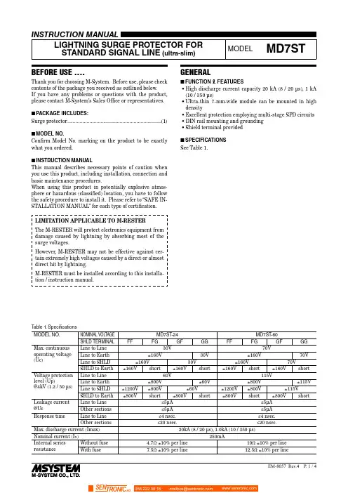
BEFORE USE ....Thank you for choosing M-System. Before use, please check contents of the package you received as outlined below .I f you have any problems or questions with the product, please contact M-System’s Sales Office or representatives. ■PACKAGE INCLUDES:Surge protector ....................................................................(1) ■MODEL NO.Confirm Model No. marking on the product to be exactly what you ordered.■INSTRUCTION MANUALThis manual describes necessary points of caution when you use this product, including installation, connection and basic maintenance procedures.When using this product in potentially explosive atmos-phere or hazardous (classified) location, you have to follow the safety procedure to install it. Please refer to “SAFE IN-STALLATION MANUAL” for each type of certification.LIMITATION APPLICABLE TO M-RESTERThe M-RESTER will protect electronics equipment from damage caused by lightning by absorbing most of the surge voltages.However, M-RESTER may not be effective against cer-tain extremely high voltages caused by a direct or almost direct hit by lightning.M-RESTER must be installed according to this installa-tion / instruction manual.GENERAL■FUNCTION & FEATURES• High discharge current capacity 20 kA (8 / 20 µs), 1 kA (10 / 350 µs)• Ultra-thin 7-mm-wide module can be mounted in high density• Excellent protection employing multi-stage SPD circuits • DIN rail mounting and grounding • Shield terminal provided ■SPECIFICATIONS See Table 1.Table 1. SpecificationsMODEL NO.NOMINAL VOLTAGE MD7ST -24MD7ST -60SHLD TERMINAL FF FG GF GG FF FG GF GGMax. continuousoperating voltage (Uc)Line to Line 30V 70VLine to Earth ±160V 30V ±160V 70V Line to SHLD±160V 30V ±160V 70V SHLD to Earth±160V short ±160V short ±160V short ±160V shortVoltage protection level (Up)@4kV (1.2 / 50 µs)Line to Line 60V 115VLine to Earth ±800V ±60V ±800V ±115VLine to SHLD±1200V ±800V ±60V ±1200V ±800V ±115V SHLD to Earth±800V short ±800V short ±800V short ±800V shortLeakage current @Uc Line to Line ≤5µA ≤5µA Other sections ≤5µA ≤5µA Response time Line to Line≤4 nsec.≤4 nsec.Other sections≤20 nsec.≤20 nsec.Max. discharge current (Imax)20kA (8 / 20 µs), 1.0kA (10 / 350 µs)Nominal current (I N )250mAInternal series resistance Without fuse 4.7Ω ±10% per line 10Ω ±10% per line With fuse 7.5Ω ±10% per line 12.5Ω ±10% per line056 222 38 18SEN TRONIC AGPOINTS OF CAUTION■ENVIRONMENT• Indoor use.• When heavy dust or metal particles are present in the air, install the unit inside proper housing with sufficient ventilation.• Do not install the unit where it is subjected to continuous vibration. Do not subject the unit to physical impact.• Environmental temperature must be within -25 to +85°C (-13 to +185°F) with relative humidity within 30 to 90% RH in order to ensure adequate life span and operation.• This unit needs a DIN rail as earth grounding bar. Ox-ide coating of an aluminium rail may lower the electric conductivity between this module and the ground. Use a steel or copper rail.■DIELECTRIC STRENGTH TESTING• The surge protector starts discharging when 160V or greater voltage (with floating shield type) or several volts (with grounding shield type) is applied between lines and earth. Remove the grounding wire before conducting a test. Be sure to return the wire after the test.■AND ....• We recommend that you keep spare surge protectors so that you can replace them when necessary.• Lightning surge can enter not only through signal lines but also through power supply lines. We recommend that you also use the Lightning Surge Protector for Power Lines for adequate protection. COMPONENT IDENTIFICATION*Option identified by model number suffix.INSTALLATIONMount the unit on a DIN rail. Once installed, do not move it to another DIN rail.■MOUNTING THE UNIT ON A DIN RAILA) Hang the upper hook of the DIN rail mounting adaptor at the rear side of unit, on the DIN rail.B) Push in the lower in keeping pressing the unit to the DIN rail.C) DIN rails generally have slight individual variability in size. If you find it difficult to push in the lower part, go back to (A) and hang the upper part more deeply onto the rail and try (B) again.■REMOVING THE UNITA) Push down the spring loader utilizing a minus screwdriv-er.B) Confirm that it is pulled enough down and pull out the lower part of the unit.C) Detach the upper part from the DIN rail.REPLACING FUSE1)Hang the tip of a minus screwdriver on the groove at ei-ther side of the fuse and push it out of the housing.2)I nsert a replacement fuse. There is no polarity for thefuse to be observed.TERMINAL CONNECTIONConnect the unit as in the diagram below .Be sure to ground the DIN rail on which the unit is mounted and cross-wire between the rail and FG terminal of the protected device as shown in Figure 1 in order to equalize the earth potential.When the unit is connected with a device which has no FG terminal, ground the surge protector only . ■EXTERNAL DIMENSIONS unit: mm (inch)8–M3 EURO■Figure 1. GROUNDINGCross-wire from the DIN rail to the metal housing of the protected device to equalize the ground potential.Ground only the surge protector when the protected device has no grounding terminal.■CAUTION WHEN WIRINGHold the module steady at the front when you tighten/loosen screw terminals.■CONNECTION DIAGRAM• Specify ‘Loop disconnect fuse’ type when multiple transmitters are connected to single power bus.• Loop disconnect fuse is used to separate a transmitter loop from the power bus when it fails in the shortcircuit mode.4 – 20mA Field-mount*1. O xide film on the surface of an aluminium rail may lower the electric conductivity between this module and the ground.Use a steel or copper rail.*2. B e sure to ground the DIN rail. Recommended grounding resistance ≤100Ω*3. C ross-wire between the DIN rail and the metal housing of the protected device to equalize the earth potential. Ground only the surge protector when the protected device has no ground terminal.*4. S hield wiring method is an example. Proceed according to the system requirements.WIRING INSTRUCTIONS■EURO TERMINALTorque: 0.3 N·mApplicable wire size: 0.2 – 2.5 mm2Stripped length: 8 mmMAINTENANCECheck surge protectors periodically. Many cases of light-ning are ignored, and even lightning at a far distance often causes inductive surges.We recommend that you check your surge protector about twice a year, before and after the rainy season. Check whenever you experience a strong lightning occurrence. Checking procedure is explained in the following:■CHECKINGWIRING1)Make sure that wiring is done as instructed in the con-nection diagram.2)Make sure that the DI N rail is connected to the metal enclosure of protected device.3)Make sure that the surge protector is securely attached to the DIN rail, and that the rail is grounded to earth.■DISCHARGE ELEMENT1)Remove all wiring connected to the surge protector when you test the module.2)Check resistance across the terminals indicated in Table 2 on the high resistance range of multimeter and confirm no conduction. The tester should show 10 MΩ or greater.3)Confirm conduction across the same terminals with a 500 V DC 1000 MΩ insulation tester. The tester should show 20 MΩ or less.With loop disconnect fuse option, confirm conduction across the following terminals on the high resistance range of multimeter. The tester should show 15 Ω or less.1 – 4,2 – 5Polarity of the insulation tester does not matter.4)I f any of the above tests shows negative, replace the surge protector.Table 2.TERM.MODEL MD7ST-xFF MD7ST-xFG MD7ST-xGF MD7ST-xGG4 – 5Yes Yes Yes Yes4 – 8No Yes Yes Yes5 – 8No Yes Yes Yes8 – 5No No Yes Yes5 – DIN rail Yes Yes No Yes8 – DIN rail Yes No Yes No Note 1: A pply (+) voltage of the multimeter to the terminal number indicated on the left side.Note 2: Polarity does not matter for the insulation tester.。
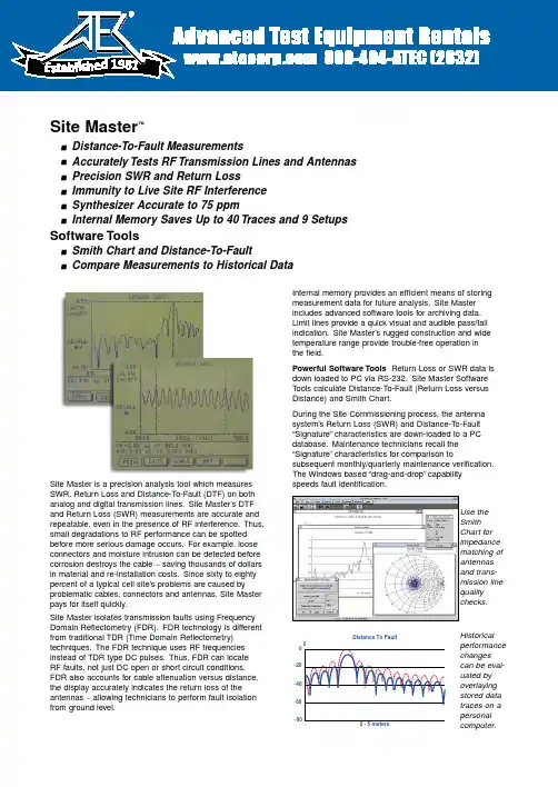
Site Master is a precision analysis tool which measures SWR, Return Loss and Distance-T o-Fault (DTF) on both analog and digital transmission lines.Site Master’s DTF and Return Loss (SWR) measurements are accurate and repeatable, even in the presence of RF interference.Thus,small degradations to RF performance can be spotted before more serious damage occurs.For example, loose connectors and moisture intrusion can be detected before corrosion destroys the cable −saving thousands of dollars in material and re-installation costs.Since sixty to eighty percent of a typical cell site’s problems are caused by problematic cables, connectors and antennas, Site Master pays for itself quickly.Site Master isolates transmission faults using Frequency Domain Reflectometry (FDR).FDR technology is different from traditional TDR (Time Domain Reflectometry)techniques.The FDR technique uses RF frequencies instead of TDR type DC pulses.Thus, FDR can locate RF faults, not just DC open or short circuit conditions.FDR also accounts for cable attenuation versus distance,the display accurately indicates the return loss of the antennas −allowing technicians to perform fault isolation from ground level.Internal memory provides an efficient means of storing measurement data for future analysis.Site Master includes advanced software tools for archiving data.Limit lines provide a quick visual and audible pass/fail indication.Site Master’s rugged construction and wide temperature range provide trouble-free operation in the field.Powerful Software Tools Return Loss or SWR data is down loaded to PC via RS-232.Site Master Software Tools calculate Distance-T o-Fault (Return Loss versus Distance) and Smith Chart.During the Site Commissioning process, the antenna system’s Return Loss (SWR) and Distance-To-Fault “Signature”characteristics are down-loaded to a PC database.Maintenance technicians recall the “Signature”characteristics for comparison tosubsequent monthly/quarterly maintenance verification.The Windows based “drag-and-drop”capabilityspeeds fault identification.Site Master™n Distance-To-Fault Measurementsn Accurately Tests RF Transmission Lines and Antennas n Precision SWR and Return Lossn Immunity to Live Site RF Interference n Synthesizer Accurate to 75 ppmnInternal Memory Saves Up to 40 Traces and 9 Setups Software Toolsn Smith Chart and Distance-To-FaultnCompare Measurements to Historical DataUse the Smith Chart for impedance matching of antennas and trans-mission line quality checks.Historical performance changes can be eval-uated by overlaying stored data traces on a personal computer.0−40−60−200 - 5 metersDistance To Fault−801981Immunity to RF Interference Site Master’s design is highly resistant to interference from incoming and ambient signals.RF suppression capabilities are realized with fre-quency-selective, narrowband receiver technology and a proprietary phase tracking synthesizer technique.RF modulation is transparent to the Site Master making it useful in any cellular modulation environment.Distance-To-Fault displays represent Return Loss or VSWR information.Measurement AccuracyMeasurement accuracy depends on the quality of the coaxial calibration components.The charts below show the Measured Value (dB) vs.Uncertainty for standard and precision calibration components.Ordering InformationModel S331 (25-3300 MHz), Built-in DTF Model S111 (300-1200 MHz), Built-in DTF Model S330 (700-3300 MHz)Model S110 (600-1200 MHz)Standard Accessories Included:• Operating Manual • Soft Carrying Case• Standard Calibration Components • AC-DC Adapter• Automotive Cigarette Lighter/12 Volt DC Adapter• One Y ear Warranty (includes battery, Firmware and Software)• 3.5 inch Floppy Disk containing Fault Location (DTF), Smith Chart and Software Management T ools • Serial Interface CableOptional Accessories/Spares:Precision N T ype Short-Open:PN 22N50Precision N T ype Load, 42 dB:PN SM/PL Test Port Cable, Armored, 1.5 meter:PN TP/EC 1.5Test Port Cable, Armored, 3.0 meter:PN TP/EC 3.0Test Port Cable, Armored, 5.0 meter:PN TP/EC 5.0Test Port Cable, Non-Armored, 1.5 meters PN TP/ECN 1.5Test Port Cable, Non-Armored, 3.0 meters PN TP/ECN 3.0Test Port Cable, Non-Armored, 5.0 meters PN TP/ECN 5.0Spare Standard N T ype Short:PN SM/STS Spare Standard N T ype Load, 35 dB:PN SM/STL Spare Soft Carrying Case:PN D41955Spare AC-DC Adapter:PN 40-74Spare Automotive 12 Volt Adapter:PN 806-62Spare Serial Interface Cable:PN 800-441Transit Case for Site Master:PN 760-194N male to 7/16 female Adapter PN 510-90N female to 7/16 female Adapter PN 510-91N male to 7/16 male Adapter PN 510-92N female to 7/16 male Adapter PN 510-9376432150 - 30 meters Distance To Fault 0VSWR 00−10−30−40−50−60−200 - 30 meters Distance To FaultRL Measured Value (dB)U n c e r t a i n t y (d B )51015202586420UNCERTAINTY CHART MODEL S110, S111Measured Value (dB)U n c e r t a i n t y (d B)51015202586420UNCERTAINTY CHART MODEL S330, S331TowerAntenna, directionalAntenna, omnidirectionalCoaxial cableCoaxial cableGrounding kitEquipment end connectorWall/roof feedthroughAngle adapter kitGrounding kitHanger mountHoisting gripCeiling adapterLow VSWR jumperLightning arresterCable hangerSite Master easily locatesfaults anywhere on the transmission lineFactory UpgradesSite Master S110 to S111ND42502Site Master S330 to S331ND42504Site Master S110 to S330ND42505Site MasterS111 to S331ND42506SpecificationsSite Master Technical Specifications*:* Specifications apply when calibrated at ambient temperature.** Fault location is done by Inverse Fourier Transformation of data taken with the Site Master.Resolution and Max Range depend on the number of frequency data points, frequency sweep range and dielectric constant of the cable being tested:Resolution (meters) = 1.5 x 10⁸/(∆Frequency √εϒ)Maximum Range = Resolution x 128*** The Immunity Uncertainty Curves represent a typical application of a worst-case scenario:Measurements were made in CW mode by injecting a signal into the Site Master through a coupler with the same signal injected through the coupled arm.In real life applications, signals are not CW but modulated and varying in frequency.Immunity is typically better when swept frequencies are used.U.S.Sales Centers:North West (408) 776-8305North East (201) 227-8999Central (214) 644-1777South West (310) 715-8262South East (301) 590-0300International Sales Centers:Europe Intl.44 (1582) 418853Japan (03) 3446-1111Canada (613) 828-4090Asia-Pacific Intl.81 (3) 3440-2770Microwave Measurements Division •490 Jarvis Drive •Morgan Hill, CA 95037-2809FAX (408) 778-0239Printed in USA11410-00173November 1995;Rev:ADS Site Master-2 /GIP-GData subject to change without noticeFor more information or a demonstrationcall the Site Master Technical Hot Line at (201) 227-8999.。

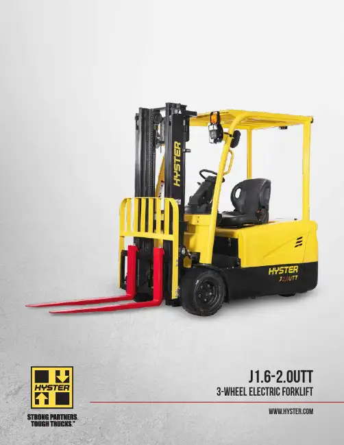
J1.6-2.0UTT 3-WHEEL ELECTRIC FORKLIFT2OVERVIEWThe cost-effective Hyster UT series is a suitable option for less demanding applications, backed by the power of the Hyster name.THE RANGEThe J1.6-2.0UTT range is available in three different capacities:1,600KG – J1.6UTT 1,800KG – J1.8UTT 2,000KG – J2.0UTTDESIGNThe design of the UT range has been engineered with the driver in mind. The ergonomically designed operator compartment, with a wide range ofstandard features and options, can be configured to the needs of the operator and the application.1HIGH STRENGTH OVERHEAD GUARDThe profiled steel overhead guard features high strength materials to enhance reliability and operator protection.2AC CONTROLLERControllers optimize battery powerconsumption. AC traction and hydraulic motors improve precision. All are easily accessible to minimize service time.3WIDE AND LOW STEPThe conveniently positioned non-slip step coupled with large grab handles provide easy and secure access to the truck.4WIDE VIEW MASTThe wide view mast delivers excellent visibility of the load and operator’s forward field of view, optimizing comfort and productivity .5SMALL, ADJUSTABLE STEERING WHEELThe small diameter steering wheel requires low effort, promoting light and precise operation. The adjustable steer column optimizes comfort and convenience.6DUAL DRIVE MOTORSThe compact structure of the drive system provides adequate access for maintenance. Precision cut gears are incorporated, leading to reduced wear and lower noise levels.FEATURES24 53163LOW COST OF OWNERSHIPThe use of high quality and robust components within the UT series deliver a reliable operation with limited wear and tear. Maintenance costs and requirements are further reduced by simple, readily available, genuine and cost effective replacement parts. HYDRAULICSHigh quality cylinders with hard chrome rods reduce seal wear for long life. A full-flow, low pressure filter on the return line keeps the hydraulic oil clean, which helps to minimize seal and pump wear. In addition, this keeps the control valve in good condition, leading to low service costs.4ENGINEERED FOR DRIVERSSAFETY AND COMPLIANCE• H igh visibility, shock absorbing mast enables soft landing• C ontrollable mast lowering speed helps to avoid damage• Secure overhead guard • Standard LED lights • O perator presence systemCOMFORT• H ydraulic power steering requires low steeringeffort for precise positioning • D river fatigue minimized by full suspension, superior comfort and lumbar support seat • A djustable steering column and seat to suit all operators• Low noise and vibration • L ow entrance step, large uncluttered floor space and ergonomically positioned pedals • E rgonomic handbrake and operator controlsPERFORMANCE• O n-demand hydraulic power steering, withtwin drive motor system, delivers superb maneuverability and low energy consumption • E xcellent stopping capability – deliveredthrough maintenance free oil-immersed brakes and regenerative braking system • S imple and clear dash display • D isplay with integrated performance selection functions • A C traction and lifting motors, with electronic control, helps improve performance • S equential seatbelt interlockSERVICE• A C traction and hydraulic motors help reducemaintenance costs • E asy service access to the controllers – mounted inside the counterweight, at waist height, protected by removable cover • I P54 Design – protects the hydraulic and drive motor components • R eadily accessible drivetrain – minimizing service time • C ANbus communication simplifies troubleshooting5Mast typeMax fork height (mm)Overall extended heightFree liftMast tilt Capacity without side shift Lowered height (mm)Lift heightWithout LBR(mm)With LBR (mm)Forward (Deg)Back (Deg)@ 500mm Single pneumatic tire (kg)@ 600mm Single pneumatictire (kg)Without LBR (mm)With LBR (mm)1.6T 1.6T 1.6T1.6T 1.6T 2LFL300019753490401035356616001435330021253790431035356616001435350022253990451035356616001435370023254190471035356616001435400025254490501035353516001435450027754990551035353514001255500030255490601035353512501120550033255990651035353511501030600035756490701035353510509402FFL3000197534904010151099066160014353300212537904310166011406616001435350022253990451017601240661600143537002325419047101860134066160013304000252544905010206015403516001330 3FFL400018504490501013858653516001330435019754840536015109903515001345450020254990551015601040351400125548002125529058101660114035130011655000222554906010176012403512501120550023905990651019251405351150103060002575649070102110159035105094065002790699075102325180535900805J1.6UTT MAST AND CAPACITY TABLENote: For integral sideshift deduct 50kg from stated capacityMAST SPECIFICATIONSMast typeMax fork height (mm)Overall extended heightFree liftMast tilt Capacity without side shift Lowered height (mm)Lift heightWithout LBR(mm)WithLBR (mm)Forward (Deg)Back (Deg)@ 500mm Single pneumatic tire (kg)@ 600mm Single pneumatictire (kg)Without LBR (mm)With LBR (mm)1.8T 1.8T 1.8T 1.8T 1.8T 2LFL300019753490401035356618001615330021253790431035356618001615350022253990451035356618001615370023254190471035356618001615400025254490501035353518001615450027754990551035353516001435500030255490601035353514501300550033255990651035353512001075600035756490701035353511009852FFL3000197534904010151099066180016153300212537904310166011406618001615350022253990451017601240661800161537002325419047101860134066180015004000252544905010206015403518001500 3FFL400018504490501013858653518001500435019754840536015109903517001525450020254990551015601040351600143548002125529058101660114035150013455000222554906010176012403514501300550023905990651019251405351200107560002575649070102110159035110098565002790699075102325180535950850J2.0UTT MAST AND CAPACITY TABLEMast typeMax forkheight (mm)Overall extended heightFree liftMast tilt Capacity without side shift Lowered height (mm)Lift heightWithout LBR (mm)With LBR (mm)Forward (Deg)Back (Deg)@ 500mm Single pneumatic tire (kg)@ 600mm Single pneumatictire (kg)Without LBR (mm)With LBR (mm)2.0T 2.0T 2.0T 2.0T 2.0T 2LFL3000197534904010545466200017953300212537904310545466200017953500222539904510545466200017953700232541904710545466200017954000252544905010545435200017954500277549905510545435180016155000302554906010545435150013455500332559906510545435130011656000357564907010545435120010752FFL3000197534904010151099066200017953300212537904310166011406620001795350022253990451017601240662000179537002325419047101860134066200016654000252544905010206015403520001665 3FFL400018504490501013858653520001665435019754840536015109903519001705450020254990551015601040351800161548002125529058101660114035165014805000222554906010176012403515001345550023905990651019251405351300116560002575649070102110159035120010756500279069907510232518053510008956SPECIFICATIONSD i s t i n g u i s h i n g m a r k 1.1Manufacturer MeasurementHyster Hyster Hyster 1.2Model designationJ1.6UTT J1.8UTT J2.0UTT 1.3Power: battery, diesel, LPG, electric mainsBattery Battery Battery 1.4Operation: manual, pedestrian, stand, seat, orderpicker Seated Seated Seated 1.5Load capacity Q (kg)1600180020001.6Load center c (mm)5005005001.8Load distance x (mm)3713713711.9WheelbaseY (mm)140014001515W e i g h t 2.1Unladen weight (max. battery)kg 3120319033802.2Axle loading, laden front / rear (max. battery)kg 4010 / 6604420 / 5104870 / 5802.3Axle loading, unladen front / rear (max. battery)kg 1480 / 16401500 / 16901580 / 1810T i r e s , c h a s s i s 3.1Tires: L=pneumatic, V=cushion, SE= superelastic SE SE SE 3.2Tire size, front 18 × 7-818 × 7-8200 / 50-103.3Tire size, rear15 × 4.5-815 × 4.5-815 × 4.5-83.5Number of wheels, front / rear (X = driven) 2x / 22x / 22x / 23.6Track width, front b10 (mm)9339339523.7Track width, rear(mm)186186186D i m e n s i o n s 4.1Mast tilt, forward α / back β degrees 6/66/66/64.2Height of mast, lowered h1 (mm)1992199219904.4Lift height “h3 (mm)3036303630454.5Height of mast, extended E h4 (mm)4030403040004.7Height to top of overhead guard m h6 (mm)2002200220044.8Seat height u h7 (mm)9659659654.12Towing coupling height h10 (mm)4454454854.19Overall length (with forks)l1 (mm)2894289431534.20Length to face of forks l2 (mm)1974197420844.21Overall width b1 (mm)1084108411404.22Fork dimensionss /e / l (mm)35 / 100 / 92035 / 100 / 92040 / 120 / 10704.23Fork carriage DIN 15173. class, A / B 2A 2A 2A 4.24Fork carriage width E b3 (mm)9509509504.25Width over forksb5 (mm)8908908904.31Ground clearance, laden, below mast m1 (mm)9090904.32Ground clearance at centre of wheelbasem2 (mm)9696964.33Aisle width with pallets 1000 mm long × 1200 mm wide Ast (mm)3290329034454.34Aisle width with pallets 800 mm wide × 1200 mm long Ast (mm)3415341534104.35Outer turning radius Wa (mm)1601160117164.36Inner turning radius b13 (mm)000P e r f o r m a n c e d a t a 5.1Travel speed laden / unladen km / h 14 / 1614 / 1614 / 165.2Lifting speed laden / unladen mm / s 352 / 500349 / 500310 / 5005.3Lowering speed laden / unladenmm / s 344 / 420382 / 421390 / 4305.6Maximum drawbar pull laden / unladen, 5 minute rating N 15500 / 1000015000 / 1050015500 / 120005.8Maximum gradeability with / without load, 5 minute rating %20 / 3020 / 3020 / 305.9Acceleration time with / without load 10m sec 4.4 / 4.3 4.4 / 4.3 5.9 / 5.65.10Service brakeHydraulic Hydraulic Hydraulic E l e c t r i c -m o t o r 6.1Drive motor rating, S2, 60min kW 2 × 5.0 2 × 5.0 2 × 5.06.2Lifting motor, S3 15% rating kW 1111116.3Battery DIN 43531 / 35 / 36 A, B, C, no 43531A 43531A 43531A 6.4Battery voltage / capacity (5hr rate)V/Ah 48 / 46048 / 46048 / 6006.5Battery weight (min / max)kg 9459451090Battery dimensionsl / w / h (mm)830 / 630 / 627830 / 630 / 627830 / 738 / 6276.6Power consumption in accordance with VDI cycle kWh / h 5.19 5.3 5.7A d d i t i o n a l d a t a8.1Drive control AC AC AC ManufacturerZAPI ZAPI ZAPI 8.2Operating pressure for attachments x bar 1451751758.3Oil volume for attachments Vmin 3838388.4Average noise level at operator's ear ¬dB (A)64.864.869.68.5Towing coupling, type DINØ32Ø32Ø32¬ L PAZ, measured according to the test cycles and based on the weighting values contained in EN12053“ Bottom of forksu Full suspension specified E Without load backrestm h6 subject to +/- 5 mm tolerance x VariableSpecification data is based on VDI 2198, with the following configuration: Complete truck with 3000mm 2-stage limited free lift mast, standard carriage and forks, overhead guard and standard superelastic drive and steer tires.7DIMENSIONSAst = Wa + x + l6 + aa = Minimum operating clearance of 200mm l6= load length7382X 152X 158306275805601802306302X 152X 15750680980ModelCompartment sizeBattery specifications Electrical Battery sizeWeightW mm (in)L mm (in)H mm (in)Voltage W mm (in)L mm (in)H mm (in)Min kg (lbs)Max kg (lbs)J1.6-1.8UTT Vertical extract 843 (33.1)634 (24.9)645 (25.3)48830 (32.6)630 (24.8)627 (24.6)898 (1980)992 (2185)J2.0UTT Vertical extract843 (33.1)752 (29.6)645 (25.3)48830 (32.6)738 (29.0)627 (24.6)1034 (1980)1142 (2515)Battery type: “EO” (without cover)Battery compartment length is measured front to rear. Battery compartment width is measured across the truck Battery lead: length 250mm (10”), bosition “B”, 2 / 0 AWGBATTERY COMPARTMENT SPECIFICATIONSJ1.6-1.8UTTJ2.0UTTHyster Company P .O. Box 7006Greenville, North Carolina 27835-7006Part No. J1.6-2.0UTT/BTG 3/2021 Litho in U.S.A.Visit us online at or call us at 1-800-HYSTER-1.Hyster, and STRONG PARTNERS, TOUGH TRUCKS, are registered trademarks in the United States and certain other jurisdictions. Hyster products are subject to change without notice.Trucks may be shown with optional equipment. © 2021 Hyster Company. All rights reserved.。
Power-LOAD Power-PRO XT XPSReduce Injuries.Reduce injuries.We at Stryker work in partnership with EMS personnel to understand the environmentin which EMS products operate and the demands that are placed on them. Teams ofengineers then focus on developing robust and reliable equipment that help make the paramedic’s job easier, safer and more efficient. Stryker EMS products are built to lastand strong enough to handle the rigorous demands of the EMS environment.23At Stryker, we put quality first in everything we do. We continually improve our quality systems to develop, produce and market products that meet or exceed the requirements of customers and regulatory agencies around the world.Safety it’s a powerful thing.SMRT – Efficient Power-PRO XT battery managementSMRT batteries with inductive charging - The SMRT Power System will give your Power-PRO cot performance. This is a tough, professional-grade system designed for the high-pressure world of EMS. The SMRT Power System eliminates the time-consuming and elaborate charging protocols and “tuning” usually required formaintaining reliable, high performance battery-powered systems. In combination with Power-LOAD it is charged while you are driving with inductive charging. This ensures a reliable operation of the system.Safety features( P ower-LOAD and Power-PRO XT)• A ngle sensors – within the system indicate the Power-LOAD lifting arms are at the correct position to release thecot from the trolley.• S upport sensors – ensure that the wheels of the cot are on the ground before the lifting arms stop supporting the cot.• S afe position feature – the Power-LOAD lifting arms will not lift if the cot is not in position and ready to be loaded.• S afe cot release – if the lifting arms have not lowered, the cot release handles will not function.• M anual override – for cot release handles on the head-end of the trolley on both the patient right and patient left that will allow manual release of the trolley head-end.• M anual back-up – lowering of lifting arms in any circumstance by pressing and holding manual lower button.• T ransfer lock override – transfer can be manually pushed into the ambulance and can be secured for transport and vice versa.• Power-LOAD battery – non-spillable battery for durability.• W ireless communication safety feature – if two cots are within the same vicinity or within the same ambulance they will not cross communicate.• S afety hook – assures handling confidence when loading and unloading in the event of power loss.• P ressure-locking valve – Power-PRO has been designed with a pressure-locking valve that prevents the cot from lowering when the manual release handle is pulled, until the pressure is released from the head and foot-end of the cot. - T his same feature exists when loading with Power-LOAD, the foot-end operator can hold the manual release valve, raise the cot legs, and push the cot into transport position.- W hen unloading, the foot-end operator can squeeze the manual release handle to lower the legs, and the cot will not lower completely until the manual override panel is used to lower the Power-LOAD lifting arms.U L recognised to UL 60601-1 (Medical Electrical Equipment, Part 1: General Requirements for Safety)C ompliant to IEC 60601-1-2 (Electromagnetic Compatibility)T ransmitter: FCC, IC, and ACMA approved, RTTE compliantB S EN 1789 European standard governing the performance and safety of road ambulances, a requirement of which is the dynamic evaluation of the cot fastener as a system to 10g in theforward, rearward, left, right and vertical directions (using a 50th percentile manikin).I PX6 refers to the product’s ability to withstand powerful jets of water without adverse effects.C E: MDD, RTTE Directive Certifications / testingsPower-Pro XTPowered ambulance cotcapacity318kgReduce the risk of injuries when raising and lowering.Medics experience frequent spinal loading due to repetitive motions such as lifting, lowering, carrying, and bending. Use of the Power-PRO XT has proven to reduce spinal loading, resulting in reduced injuries, lost or modified workdays and workers’ compensation costs, and intends to increase recruitment and retention.1Lift-capable safety barAssures handling confidence. Reduces lift height for smaller operators.Oversised wheelsRequires less force to roll, improving manoeuvrability over rough terrain.Retractable head sectionThe retractable head section with safety bar has conveniently located release handles that retract the head section into the cot. The safety bar release is designed to keep hands away from the cot mechanism.Battery pack release controlAccessible and easily changed.Head and foot-end lift and grip sectionErgonomic lifting handles optimised to 30 degrees. Grips have a textured, durable, nonslip surface for operator control.US patented x-frameWill not hot drop.Key features and benefits Power-PRO XT 6506:• Hydraulic lift system• Settable load height with jog function • Power-LOAD compatibility option• Shock, flat leg or optional knee gatch positioning• Retractable head section41. Evaluation of Medical Cot Design Considering the Biomechanical Impact on Emergency Response Personnel – T.K. Fredericks, S.E. Butt, K.S. Harms, J.D. Burns XXVth Annual Occupational Ergonomics and Safety. Conference.Power-LOADPower-loading cot fastener systemLifts and lowers the cot into and out of the ambulance, reducing spinal loads and the risk of cumulative trauma injuries.The Power-LOAD cot fastener system is designed to improve operator and patient safety by supporting the cot throughout the loading and unloading process. The reduction in spinal load helps prevent cumulative trauma injuries. Power-LOAD wirelessly communicates with Power-PRO cots for ease of operation and operator convenience.1Key features and benefits• Lifting arms• Head end LED indicators • Cot release handles• Linear transfer system • Duplicate LED indicator • Manual trolley release • Inductive charging • Control panel• Battery indicator • Foot end release • Safety hook• TrolleyHead-end LED indicators Keeps operator informed of position status. Solid green when in position or ready to transport; flashing amber when not in position or not ready to transport.Manual cot release Allows cot to be unlocked once all the wheels are on the ground.Lifting arms Battery-powered hydraulic lift system supports the cot and patient during loading and unloading.Control panel withbattery indicatorAllows complete operation formanual cots as well as theoperation of powered cots inthe event of a power loss.Linear transfersystemSupports and guides thecot during loading andunloading.51. Evaluation of Medical Cot Design Considering the Biomechanical Impact on Emergency Response Personnel – T.K. Fredericks, S.E. Butt, K.S. Harms, J.D. Burns XXVth Annual Occupational Ergonomics and Safety. Conference.variety of patients and environments.* Power-PRO XT, Power-PRO TL and Performance-PRO XT• Increased patient surface(surface mini 58 cm, surface maxi 84 cm)• A djustability for patients and environments • 7 locking positions• I ntegrated into cot – Always there• E asily retrofitted to existing compatible cots • R elease handles designed to keep hands away from the cot mechanism• D urable aluminium over-mould design • M attress design reduces transfer gap • Enhanced patient comfort• C ompliant with tip stability and dynamic crash certifications 11 Certified to IEC 60601-1 for Power-PRO XT, Power-PRO TL andPerformance-PRO XT.Key features and benefitsDurabilityEngineered for durability with an aluminum core.Release handlesRelease handles designed to keep hands away from the cot mechanism.Reduced transfer gapMattress design reduces transfer gap.+38%+38%surface areasurface mini 58 cmsurface maxi 84 cm71 Additional weight compared to standard siderails not including mattress 2Width is measured at widest point (Standard bolster mattress 19 in / 48 cm) 3 Certified to IEC 60601-1 for Power-PRO XT and Power-PRO TL, and Performance-PRO XT.Stryker reserves the right to change specification without notice. All numbers rounded to nearest whole value.Power-LOAD specificationsModel Number 6390 Length Overall 241 cm Minimum 228 cm Width 62 cm WeightTotal Weight 96.5 kg Floor Plate Assembly 7.5 kg Anchor Assembly 10.5 kg Transfer Assembly 30.5 kg Trolly Assembly 48 kgMaximum Weight Capacity 1318 kg Minimum Operator Required Occupied Cot 2 Unoccupied Cot 1Recommended Loading Height 56 cm to 91 cm Battery 12v, 5 Ah LeadAcid Battery (6390-001-468)1M aximum weight capacity represents patient weight. Safe working load of 870 lb (395 kg) represents the sum of the cot total weight and patient.Meets dynamic crash standards for Power-PRO XT (BS EN-1789) and Performance-PRO XT (BS EN-1789).Stryker reserves the right to change specifications without notice. In-service video included with every order.Power-PRO XT specificationsModel Number 6506 Overall 206 cm LengthStandard 206 cm Minimum 160 cm Overall Width 58 cm Maximum Weight Capacity 2 318 kg Height Range (to litter range) High 1 105 cm Low 36 cm Weight 2 57 kgBackrest Articulation 30o to 75o Recommended Loading Height 4Up to 91 cm1H eight measured from bottom of mattress, at seat section, to ground level.2 Cot is weighed with one battery pack, without mattress and restraints.3 With fowler option (6506-012-004).4C an accomodate load decks up to 91cm. Load height can be set between 66 cm and 91 cm.Stryker reserves the right to change specifications without notice. In-service video included with each order.Cot is compliant to the BS EN 1865-2:2010+A1:2015 standard with the 1865 fowler option (6506-012-004). Cot is compliant to the BS EN 1865-3:2012+A1:2015 standard with the XPS option (6506-040-000).XPS expandable patient surfaceIncludes 2 XPS siderails XPS mattress Weight 14 kg (8 lb)7 Locking positions Between 10°-52°Surface area xpansion Locking angle Width total surface area 10o 23 in (58 cm) 17o 25 in (64 cm) 24o 27 in (69 cm) 31o 29 in (74 cm) 38o 30 in (76 cm) 45o 32 in (81 cm) 52o33 in (84 cm) Height 10 in (25 cm) Length30 in (76 cm) XPS mattress width 2 23 in (58 cm) XPS compatible cots 3Power-PRO XT Model 6500/6506 Power-PRO TLModel 6550Performance-PRO XTModel 6085/6086EMSThis document is intended solely for the use of healthcare professionals.A healthcare professional must always rely on his or her own professional clinical judgment when deciding whether to use a particular product when treating a particular patient. Stryker does not dispense medical advice and recommends that healthcare professionals be trained in the use of any particular product before using it in surgery.The information presented is intended to demonstrate the breadth of Stryker product offerings. A healthcare professional must always refer to the package insert, product label and/or instructions for use before using any Stryker product.Products may not be available in all markets because product availability is subject to the regulatory and/or medical practices in individual markets. Please contact your Strykerrepresentative if you have questions about the availability of Stryker products in your area.Stryker Corporation or its divisions or other corporate affiliated entities own, use or have applied for the following trademarks or service marks: Stryker Power-PRO XT, Power-LOAD, SMRT and XPS. All other trademarks are trademarks of their respective owners or holders.The products depicted are CE marked in accordance with applicable EU Regulations and Directives.*PWLOADBRO1EN*Copyright © 2020 Stryker8PWLOADBRO1EN SDL 02/20202017-15354。
目录第一部分 梅兰日兰UPS系列-------------------------------------------------------------------------------2 梅兰日兰系列UPS列表----------------------------------------------------------------------------------------2 Comet 3000系列-----------------------------------------------------------------------------------------------2 基本技术参数--------------------------------------------------------------------------------------3 Galaxy 3000系列---------------------------------------------------------------------------------------------4 基本技术参数--------------------------------------------------------------------------------------5 Galaxy PW系列-------------------------------------------------------------------------------------------------6 基本技术参数--------------------------------------------------------------------------------------7 Galaxy 1000 PW系列-----------------------------------------------------------------------------------------8 基本技术参数--------------------------------------------------------------------------------------9 Galaxy 5000系列--------------------------------------------------------------------------------------------10 基本技术参数-------------------------------------------------------------------------------------11 Galaxy 6000系列--------------------------------------------------------------------------------------------12 基本技术参数-------------------------------------------------------------------------------------13 Planet 3000系列--------------------------------------------------------------------------------------------14 基本技术参数-------------------------------------------------------------------------------------15 船用设备--------------------------------------------------------------------------------------------------------16 第二部分 STS/电池/THM产品----------------------------------------------------------------------------17 梅兰日兰Galaxy STS----------------------------------------------------------------------------------------17 梅兰日兰蓄电池----------------------------------------------------------------------------------------------18 梅兰日兰THM有源滤波器------------------------------------------------------------------------------------19冗余系统或增容系统;可30 KVA内置手动维修旁路,维修时不需中断向负载基本技术参数采用斜坡启动以防止瞬间启动电流的基本技术参数基本技术参数基本技术参数基本技术参数方法,定期检查全部操作电路,确保功能有效,并可通过电池监视器(选件)在电池放电时间结束后将电池断开,从而避免电池因深度放电而带来的损坏;先进的管理功能:实现部件级的当前状态远程诊断,对系统运行的历史纪录种语言和图形显示的控制器,即使是并联系统基本技术参数船用设备。
西斯特姆:全力推广自动化立体货柜——访西斯特姆(中国)科技有限公司Modula事业部销售主管倪铠任芳【期刊名称】《物流技术与应用》【年(卷),期】2017(022)002【总页数】3页(P66-68)【作者】任芳【作者单位】【正文语种】中文目前,西斯特姆自动化立体货柜在中国市场的保有量已经超过200台,覆盖汽车、电子制造、航空航天等领域。
随着工业4.0的发展,智能物流正当其时,更多的西斯特姆自动化立体货柜项目将在中国市场落地。
中国物流行业在近十年来的高速发展之下,释放出巨大的物流设备需求空间,特别是随着电商行业、智能制造的发展,智能化物流装备的需求与日俱增,因此持续吸引着国际知名物流设备提供商的目光,其中就包括提供各类堆垛机、自动化立体货柜等核心物流设备的意大利西斯特姆集团(System Group)。
西斯特姆(中国)科技有限公司Modula事业部销售主管倪铠表示,今后公司在中国市场将致力于Modula立体仓储货柜及WMS软件的研发、生产及销售,从而为用户提供最优的智能仓储系统解决方案。
为何西斯特姆中国将把业务重心移向自动化立体货柜市场?其自动化立体货柜有何优势?接下来公司又将如何拓展中国市场?对此,倪铠在采访中进行了详细解答。
西斯特姆(中国)科技有限公司(System China,以下简称“西斯特姆”)是西斯特姆集团全资子公司。
西斯特姆集团成立于1970年,经过40多年的发展,形成了包括现代物流仓储设备、陶瓷等在内的九大工业自动化业务分支。
其中,西斯特姆集团提供的现代物流仓储设备主要包括重型托盘堆垛机、Miniload箱式堆垛机、Modula立体仓储货柜,以及AGV等产品。
早在2000年,西斯特姆集团各大业务便进入中国市场,并在苏州成立西斯特姆(中国)科技有限公司,随后在佛山、淄博和北京分别设立分公司,提供以上高端自动化物流设备。
自动化立体货柜作为现代化的仓储设备,以“货到人”的方式实现了物品的自动化存取,同时可以充分利用空间高度,提升地面利用率。
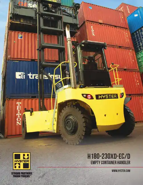
H180-230XD-EC/D EMPTY CONTAINER HANDLERRELIABILITY IN CONTAINER HANDLINGThe Hyster® H180-230XD-EC/D series benefits from over 50 years of heritage in container handling and spreader design. These empty container handling machines offer fast handling, reliable proven components, and give an excellent return on your investment.Hyster H180-230XD-EC/D empty container handlers can handle up to 23,000lbs capacity, allowing the trucks to easily pick two 40-foot reefer units at once. These trucks are designed to perform and last while handling the heaviest double container loads. With components designed for double handling, imagine what they can do in your single handling application.You will appreciate the performance from the powerful and efficient Cummins QSB 6.7L engine and reliable ZF 5WG 211 transmission. The productivity benefits that come from Hyster single or double spreader give you more options than ever to move additional containersin less time. Features such as powered pile slope, automatic extend-retract of the spreader, auto throttle up and true inching allow for safe, accurate and smooth positioning of containers – even up to 9-high.23PERFORMANCE IS KEYThe Tier 4 Final Cummins QSB 6-cylinder diesel engine delivers 231 peak HP and 770 lb-ft of maximum torque, featuring cooled exhaust gas recirculation (EGR) technology with selectivecatalytic reduction (SCR) and an integrated diesel exhaust fluid (DEF) delivery system. A 2-stage diesel oxidation catalyst (DOC) is also included for particulate matter (PM) reduction.Innovative selectable ECO performance modes, plus the 5-speed transmission and variabledisplacement pumps, offer excellent fuel economy and maximum productivity providing up to 15% fuel consumption reduction versus previous Tier 3 powered trucks. Hibernate idle can also save fuel by lowering engine speed when functions are not being used.Automatic engine shutdown saves fuel byshutting down the engine if the driver leaves the seat or the engine idles for too long, after a pre-set (adjustable) time. On-demand hydraulics keep oil temperature lower to protect hydraulic components. Plus an optional hydraulictemperature protection system is available toderate the truck when the temperature threshold is reached.TIER 4 FINAL INTEGRATED POWERTRAINCummins QSB 6-cylinder diesel engine delivers 231 peak HP and 700 lb-ft of maximum torque. • ZF 5-Speed 5WG 211 powershift transmission • Wastegate turbocharger, water cooled • Automatic throttle-up• On-demand hydraulic system• 24V electrical system with 120 amp alternatorTIER 3(Not available in US OR Canada)• The drive train protects itself from excessive temperatures and pressures:– high coolant temperatures and low levels – high air intake temperatures – low engine oil pressure– high transmission oil temperatures and low pressure• Variable geometry turbocharger, water cooled • Rugged and capable ZF 5-speed 5WG 211 powershift transmission with proven field experience and reliability• 24V electrical system with 120 amp alternator • Automatic throttle-up on hoist and tilt enables engine to operate in most efficient rpm range4THE RIGHT SPREADER FOR YOUR OPERATIONA comprehensive selection of single and double handlingspreaders are available, featuring vertical twistlocks or hook & sideclamps, to suit your specific application. These spreaders allowoperations to handle most common types of containers includingISO, WTP and domestic containers.Container sensing systemsupports safe handlingwhen transporting twocontainers.Centralized greasing onthe spreader reduces thenumber of grease pointsfor easier maintenance.Smart camera systemsare available for additionaloperator support.Ample sideshift allowsoperators to easilyresposition offset loads andhandle two reefers with thegen set on the same side.The innovative spreader designenables the operator to see thetwistlocks or hooks in everyload position.The optional auto extend-retractfeature further assists operatorsby adjusting the spreader to a20ft or 40ft container size at thetouch of a button.56Hyster Company is known for tough lift trucks, but we’re also recognizedfor ergonomically advanced lift trucks. A spacious, comfortable operator environment and an operator interface with ergonomically designedcontrols helps elevate productivity while minimizing operator fatigue.OPERATOR COMFORTThe H180-230XD-EC/D series operator cab provides aspacious cockpit style cabin that keeps all truck informationand controls within reach.A variety of seat configurations are offered to suit operatorpreference including mechanical or air suspension, cloth orvinyl cover, lumbar support and ventilated or heated seats.The air conditioning system can be pre-set for automaticclimate control and the high and rear louvers provide directair flow toward the operator.The ergonomically designed, seat-mounted controlarm is fully adjustable and includes a wrist cushion andredesigned joystick to help reduce fatigue when operatingthe hydraulics. The intuitive joystick, integrated in thearmrest, is designed for simplicity to provide easy, preciseoperation of the mast and spreader. The modular designof the control arm makes it possible to cover almost anypossible truck configuration while being easily serviceable.The reliable CANBUS controls all main components.The new 7” full color, touchscreen Integrated PerformanceDisplay shows all truck activity, allows for easy access tochange or calibrate truck settings and is integrated withHyster Tracker telemetry system.Optional secondary displayavailable specifically fordouble handling.AC ventsDeluxe air seatoptions availableHD JoystickXD Joystick7VISIBILITYSuperb visibility through the mast allows easy positioning of containers at anyheight for more precise and efficient load handling. Optional raised cabin allows the operator to view and inspect the top of the container when positioned on a chasis.The cab’s structural design, curved tempered glass windshield and scratch resistant top glass creates optimumvisibility for container stacking. Rearward visibility is outstanding with the cablocation engineered to enable sweeping views over both the left and right shoulders.Optimize the operator's vantage point with the optional automatic tip-up cab which can provide greater operator comfort when stacking containers above 4 high. Smart camera options and radar systems are also available to assist in visibility of key areas.8SIMPLIFIED SERVICEABILITYHyster ® trucks have been designed with the service technician in mind. Easy access to the engine, hydraulics and other major components are enabled with a large hinged hood and lift off front covers. The tip back cabin provides ample service access to components located under the cabin.Daily operator checks are completed with ease given the ready access to all checked items, filter indicators and sight glass on hydraulic oil tank. Preventative maintenance service interval is 500 hours. Hydraulic oil service interval can be extended to 10,000 hours using regular oil sampling. The integrated performance display offers high-level on-board diagnostics allowing for advanced and quick troubleshooting without having to connect a laptop to the truck.ADDITIONAL ENHANCEMENTS• Broad, slip resistant running boards• Optional utility toolbox and storage compartment• The hydraulic oil tank features a sight glass and magneticdrain plugs for ease of maintenance• Clean hydraulic hose and electrical harness routing andclampingAn optional automatic greasing system is available. Automaticgreasing will significantly lower total cost ofownership by eliminating maintenance costs of manually greasing each component. By ensuring that greasing is completed, component service life can be extended.AUTOMATIC GREASINGTake your fleet operation to the next level with wireless asset management from Hyster, standard on all Hyster Big Trucks. Hyster Tracker provides a scalable solution for fleets. From monitoring truck utilization to limiting operator access, Hyster Tracker allows you to track your fleet at your fingertips.HYSTER TRACKER: WIRELESS ASSET MANAGEMENTTRACKER9Optional utility toolboxand storage compartment Broad, slip resistant running boardsTRAVEL SPEEDS12.4 mph (20 km/h) - laden 15.5 mph (25 km/h) - unladenLIFTING SPEEDS91 ft/min (0.46 m/s) - laden 122 ft/min (0.62 m/s) - unladenLOWERING SPEEDS108 ft/min (0.55 m/s) - laden 108 ft/min (0.55 m/s) - unladenHEAVY DUTY PRODUCTIVITYHyster ®H180-230XD-EC/D container handling trucks deliver high productivity with 4-mode average speeds* of 107 ft/min (0.54 m/s), competitive in the industry at rated laden container handling capacities.For optimal performance and durability, the variable lap mast features:• significantly lower load roller forces • less mast deflection • higher torsional rigidity• heavy duty 2 chain system with large diameter sheavesThis design enhances structural strength, contributing to lower costs and reducing downtime.*Average speed calculated using: laden lift speed (ft/min) at full rated capacity; unladen lift speed; laden lowering speed at full rated capacity; unladen lowering speed.1011Service — Your local Hyster ® dealer offers a flexible, customized and comprehensive maintenance plan based on each lift truck’s operation environment. Hyster service programs offer scheduled inspections and maintenance, along with quick, responsive service dispatched to your location.For nearly 90 years, Hyster has conquered the world’s most demanding applications. In the 1920s Hyster started as a manufacturer of lifting machines used in the rigorous logging industry of the United States’ Pacific Northwest. A few years later the first forklift trucks were invented and the Hyster brand quickly gained its reputation for rugged quality. Hyster ® lift trucks are designed to lower your cost of operations. Every truck we make — whether powered by gasoline, LPG, diesel, lead acid, CNG, lithium-ion or hydrogen fuel cells — is purpose-built to excel in its application. Every truck is also backed by an unmatched network of specialists.Special Products Engineering Department (SPED) — Different materials require different handling.That’s why we can work with you to customize your lift trucks. From strobe lights to specially made forks, SPED has the tools to help you get the job done right.Hyster Capital — We can arrange solutions for special financing requirements, taking the difficulties out of buying the equipment you need. Whether you purchase or lease a new or used lift truck, Hyster Capital offers superior service and competitive rates. Rental Products — When leasing or buying isn’t a practical option, we have access to more than 14,000 units for short- and long-term rental. We’ll help you maintain output in a cost-effective manner.Parts — With genuine Hyster ® replacement parts and UNISOURCE TM parts for all makes of lift trucks, we are your one-stop source for lift truck parts. In fact, we offer more than 7 million part number crosses for most brands of materials handling and other in-plant mobile equipment.Hyster Fleet Services — Even if you operate other brands, we can manage your maintenance and replacement plan. We can offer complete fleet analysis, fleet history summary and a cost-effective proposal for replacement and scheduled maintenance.Operator Training — Proper education in operating lift trucks minimizes the risk of injuries due to accidents while increasing productivity. Hyster offers OSHA-compliant materials that support the training of qualified operators.Dealer Network — Our Dealer Network can offer the expertise of fleet managers, parts suppliers, capital procurement specialists and trainers. Carefully chosen dealers fully understand customer applications, assist in selecting the right lift truck and provide fast, reliable support.SPEDINNOVATIVE TRUCKS ENGINEERED TO MEET THE MOST DEMANDING APPLICATIONSHyster CompanyP .O. Box 7006Greenville, North Carolina 27835-7006Part No. H180-230XD-ECD/B 7/2020 Litho in U.S.A.T rucks may be shown with optional equipment. © 2020 Hyster Company . All rights reserved.Hyster , and STRONG PARTNERS. TOUGH TRUCKS. are registered trademarks in the United States and certain other jurisdictions. Hyster products are subject to change without notice.Visit us online at or call us at 1-800-HYSTER-1.。
R30XMA3 SERIESPRODUCT BROCHURE2† Rated load figures are based on 3000 lb (1361 kg) load and a 24” load center.NOTE: Performance specifications are for truck with standard equipment. Performancespecifications are affected by the condition of the vehicle and how it is equipped as well as the nature and condition of the operating area. If these specifications are critical, the proposed application should be discussed with your dealer.Lift heights over 360" (9144 mm) maximum fork height may require reduced capacity depending upon OEC dimensions.3Right angle stack and equal intersecting aisle dimensions provided with a 40” wide x 48” long pallet load, allowing zero clearance.1Speeds are the same in either direction, with or without rated load. Steer angle <10 degrees.2Optional with Hyster Power Cellect ™CERTIFICATION: These Hyster ® lift trucks meet the design and construction requirements of B56.1-1969, per OSHA Section 1910.178(a)(2), and also comply with the B56.1 revision in effect at time of manufacture. Performance specifications are for a truck equipped as described under standard equipment on this technical guide. Performance specifications are affected by the condition of the vehicle and how it is equipped, as well as by the nature, condition of the operating area, proper service and maintenance of the vehicle. If these specifications are critical, the proposed applica-tion should be discussed with your dealer.Battery compartment length is measured from front to rear. Battery compartment width is measured across truck. SB350 amp “red” connector, cable position B, cable length 16”(405mm). Maximum cable gauge 1/0 AWG battery with lid will NOT fit in battery compartment. Battery weight range 1500 - 2000 lb. Amp hour capacity min/max - 24 volt truck 960/1240. 36 volt truck 600/775.Note: Speed limits are for trucks at operating temperature with fully charged battery. Speeds are the same in either direction, with or without rated load. For lift heights between 24.0” (610 mm) and 272.0” (6909 mm), traction speed is reduced when steering angle exceeds 10°.* T ravel above 272.0” (6909 mm) fork height requires a High level traction option. Capacity reduction required.Contact your local dealer for additional information.。
A25-30XNT SERIES BROCHURE/TECHNICAL GUIDEA25-30XNT FEATURES & OPTIONSThe A25-30XNT series has been designed to maneuver in the tightest of spaces and to move pallets in containers and warehouses, delivering a cost effective solution to meet the requirements of applications where space is at a premium. This series offers many functions and features, including extended shift performance settings and a high mounted Multifunction Display, which are standard across the range of Hyster® electric forklift trucks.DEPENDABILITY• Strong chassis construction provides excellent durability and stability, ensuring the operator can maneuver and carry out handling operations with confidence, enhancing productivity.• The use of proven components, such as O-ring faceseal fittings and sealed electrical connectors, as wellas a CANbus communications network ensure longterm reliability.• Hall-Effect sensors are virtually maintenance free, making the truck more reliable and decreasing downtime.• AC motor technology allows the truck to work longer and more reliably, reducing downtime.• The Auto Deceleration System automatically slows the truck when the operator’s foot is removed from the accelerator, reducing brake usage and associated brake maintenance requirements.• The unique Power-Assisted Braking System further increases brake and drivetrain life by automatically utilizing traction motor braking in proportion to operator brake pedal pressure, reducing the demand on the service brakes. The rugged drum-type brakes feature a strengthened “backing plate” for excellent durability.• A steel hood and durable side covers provide increased resistance to impact damage and general wear and tear. LOW COST OF OWNERSHIP• A25-30XNT trucks provide tremendous flexibility to customize the truck’s hydraulic and traction performance to your application. A trained Hyster technician can maximize your truck’s performance, whether it requires extended battery shift life, aggressive performance or fast travel speeds for long hauls.• The Pacesetter Vehicle System Manager (VSM) continuously monitors and controls all major truck functions for efficiency and proper operation.• Durable, quality components mean long term reliability and lower maintenance costs. Virtually maintenance-free components, such as AC motors, allow for 500-hour service intervals.• A thermal management system protects the motorsand controllers, leading to reduced maintenance costs.• Fast delivery of diagnostic information allows precise troubleshooting, easy maintenance planning andlower costs.ERGONOMICS• This truck has been intelligently designed, focusing on the operator. Generous foot space, an intuitive pedal arrangement and a low step height offer a comfortable working space for the operator. This means on/off access and driving in reverse cause less fatigue over long shifts.• The operator compartment features a standard non-suspension vinyl seat. Full suspension seats are available, which help to provide optimum operator comfort and a smooth ride.• A class leading low noise level of 59dB(A) reduces the stress on operators making them more productive by ensuring that they are comfortable for longer amountsof time.• The optional adjustable mini-lever module armrest with built-in hydraulic controls, integrated directional control, power disconnect button and horn offers the ultimate in comfort and control.• A display mounted in the upper right hand corner of the overhead guard keeps the operator’s field of vision clear and provides at-a-glance information regarding truck operating conditions and performance. PRODUCTIVITY• 24-volt rear-wheel drive with AC motors throughout provides smooth acceleration and excellent travel, torque and lifting performance, delivering efficient and productive load handling.• The A25-30XNT is the most compact truck Hyster offersin its class, with the tightest turning circle for excellent maneuverability in working aisles. This allows the operator to move faster with more confidence in restricted spaces or congested loading/unloading bays. An overall truck width of 39.2 inches facilitates block stacking in tight spaces.• The VISTA TM mast offers generous visibility allowingthe operator to work quicker when picking and depositing loads.• With the Extended Shift feature turned off, the truck delivers a competitive top speed of 7.5 mph (rated load) and lifting speed of 59 ft/min (rated load).23A25-30XNT FEATURES & OPTIONSSERVICEABILITY• The steer column includes a diagnostic port which allows trained dealer technicians to connect the PC Service Tool for easy access to the truck’s on-board diagnostics and programming.• Easily removable rear cover provides no-hassle access to power contactor, fuses and relays.SERVICEABILITY (CONTINUED)• The truck is fully serviceable without having to remove the battery – the motor, pump, controller and oil tank are easily accessible.• Downtime for service requirements is minimized, thanks to features such as maintenance-free AC motors, DIN wheel nuts, self-adjusting service brakes and gear-driven steering (no chain – no lubrication required), as well as extended service intervals.• Standard service interval is 6 months / 500 hours, the drive axle / transmission oil change is 4000 hours, and the hydraulic oil change is 4000 hours. The standard warranty is 12 months / 2,000 hours and the powertrain warranty is 36 months / 6,000 hours .OPTIONS• Five different mast offerings: two 2-stage and three 3-stage• Various length forks• Integral Hook Type Sideshift• Non-marking, pneumatic shaped solid tires• Full suspension vinyl and cloth seats with and without swivel• Telescopic steering column with tilt memory • Dual rear view mirrors • Single panoramic mirror • Keyless Start• Operator Password Start Interlock • Operator daily checklist • Monotrol ® pedal • LED light package • Visible alarm• Audible backup alarm • DC to DC converters • Load weight indicator • Impact monitor • System monitoring • TouchPoint mini-levers • Return to Set Tilt (RTST)• Cooler / Freezer construction package4A25-30XNT DIMENSIONSCircled dimensions correspond to the line numbers on the tabulated chart inside the Technical Guide. Dimensions are in inches (millimeters).***1031191125156282423181627115A25-30XNT DIMENSIONSG E N E R A L1Manufacturer Hyster Hyster 2Model Designation A25XNTA30XNT3Power Electric 4Operation Sit5Rated Capacity lb (kg)2500 (1134)3000 (1361)6Load Centerin (mm)24 (610)T I R E S & W H E E L S7Tire Type - Cushion, Solid, Pneumatic, etc.Front / RearPneumatic Shaped Solid / Pneumatic Shaped Solid8Tire SizeFront / Rear in18 x 7-8 / 18 x 7-89Wheels - Number X=Driven Front / Rear 2 / 1X10Tread ¢ Tires Std / Wide in (mm)32.9 / 35.3 (836 / 896)D I ME N S I O N S11Mast TiltStd degrees 5F / 5B 12Mast - Lowered Height Std Mastin (mm)78 (1980)13Free Lift - Top of Fork Std 2 Stg LFL Mastin (mm) 5 (140)Opt 3 Stg FFL Mast with / without LBR in (mm)33 / 61 (849 / 1572)14Lift Height - Top of Fork Std 2 Stg LFL Mastin (mm)112 (2860)15Mast - Extended Height Std Mast with / without LBR in (mm)161 / 133 (4089 / 3368)16Overhead Guard Height Std / Optin (mm)81.1 / 77.9 (2060 / 1980)17SIP to Bottom Std OHG Nominal Std / Susp / Swivelin (mm)39.8 / 38.6 / 38.7 (1011 / 982 / 984)18Tow Pin Height Vertical Center of Pin in (mm)24.2 (615)19Overall Width Std / Wide Treadin (mm)39.2 / 41.6 (996 / 1056)20ForksThickness x Width x Length in (mm) 1.6 x 3.1 x 43.3 (40 x 80 x 1100)21Standard Carriage Width Class IIin (mm)35.7 (907)23Ground Clearance Lowest Point NL / RL in (mm) 3.3 / 2.9 (86/74)24Ground Clearance Center of Truck NL / RL in (mm) 3.5 / 3.3 (88 / 85)25Load Distance Center of Wheel to Face of Forks in (mm)12.8 (326)26Battery Compartment Height in (mm)25 (635)Width in (mm)32.9 (835)Lengthin (mm)17.3 (439)19.4 (493)27Length to Face of Forks Chassis Lengthin (mm)67.9 (1724)70.0 (1778)28Wheelbasein (mm)46.0 (1168)48.1 (1222)29Right Angle Stack (See Note 2)in (mm)119.1 (3025)121.2 (3079)30Equal Aisle 90˚ Intersecting Aisle in (mm)66.3 (1683)66.9 (1700)31Outside Turning Radius in (mm)55.0 (1398)57.2 (1452)W E I G H T 32Truck Weight Without Battery NL lb (kg)4560 (2068)4830 (2191)33Axle Loading - Front Static with Max. Wt. Battery NL / RL lb (kg)2702 / 7206 (1226 / 3269)2783 / 8083 (1262 / 3666)34Axle Loading - Steer Static with Max. Wt. Battery NL / RL lb (kg)3394 / 1389 (1539 / 630)3663 / 1363 (1662 / 618)P E R F O R M A N C E35VoltageVOLTS 2436Travel SpeedExtended Shift OFFNL / RL mph (km/h)7.8 / 7.5 (12.5 / 12.0)Extended Shift ON NL / RL mph (km/h)7.2 / 6.3 (11.6 / 10.1)37Lift SpeedStd 2-Stg LFL MastNL / RL ft/min (m/sec)101 / 59 (.51 / .30)Opt 3-Stg FFL Mast NL / RL ft/min (m/sec)94 / 45 (.48 / .23)38Lower SpeedStd 2-Stg LFL MastNL / RL ft/min (m/sec)91 / 98 (.46 / .50)Opt 3-Stg FFL Mast NL / RL ft/min (m/sec)85 / 98 (.43 / .50)39Gradeability5 Minute RatingNL / RL %24.3 / 16.322.4 / 14.560 Minute Rating NL / RL % 4.0/3.2 3.4/2.940Drawbar Pull5 Minute RatingNL / RL lbf (N)1399 / 1445 (6221 / 6426)1403 / 1397 (6242 / 6212)60 Minute Rating NL / RLlbf (N)219 / 214 (975 / 951)218 / 212 (970 / 942)41BrakeMethod of ControlService / Parking Hydraulic / MechanicalMethod of OperationService / ParkingFoot / Lever E L E C T R I C42Battery Type Lead Acid 43Traction Motors 60 Minute Rating hp (kW) 6.3 (4.7)44Pump Motor 15 Minute rating hp (kW)8.0 (6.0)45Traction Motor Type / Control Method AC / Transistor 46Pump Motor Type / Control Method AC / Transistor 47Number of Speeds Traction / Pump Infinitely Variable O T H E R48Step Height in (mm)19.1 (485)49Floor Height Lowest Point in (mm)20.6 (522)50Attachment Relief Pressure psi (bar)2248 (155)51Auxiliary Oil Flow gal/min (l/min) 5.3 (20)52Sound Level Measured per ANSI B56.11.5dB (A)59Above specifications, unless otherwise listed, are for a standard truck without optional equipment.Right Angle Stack and Equal Intersecting Aisle dimensions provided with a 48" long and 40" wide palletload, allowing zero clearance.CERTIFICATION: Hyster lift trucks meet the design and construction requirements of B56.1-1969, perOSHA Section 1910.178(a)(2), and also comply with the B56.1 revision in effect at time of manufacture.Certification of compliance with the applicable ANSI standards appears on the lift truck.NOTE 1: Performance specifications / ratings are for truck equipped as described under StandardEquipment in this Technical Guide. Performance specifications are affected by the condition ofthe vehicle and how it is equipped, as well as by the nature and condition of the operating area.Specifications are subject to change and the proposed application should be discussed with yourauthorized Hyster Company Dealer .NOTE 2: The Industrial Truck Association (ITA) defines the formula for calculating Right Angle Stack on 3-wheel trucks with counter rotating load wheels as: (For a 40” wide by 48” long pallet load.) Hyster uses the above ITA formula tocalculate Right Angle Stack on our 3 and 4 wheel trucks with a zero turnsteer axle and counter rotating load wheels.Some documentation incorrectly calculates Right Angle Stack on a3-wheel zero-turn truck with counter rotating load wheels using thefollowing formula: . This formulagenerates a value which is invalid and lower than actual Right AngleStack. When making comparisons, be sure the correct ITA formula is usedto calculate Right Angle Stack.6BATTERY AND MAST DIMENSIONSKEY PERFORMANCE DIFFERENCESModel Designation A25XNT A30XNT J30XNT Rated Capacity @ 24" LC lb (kg)2500 (1134)3000 (1361)3000 (1361)Volts242436Travel Speed Extended Shift OFF NL / RL mph (km/h)7.8 / 7.5 (12.5 / 12.0)7.8 / 7.5 (12.5 / 12.0)9.8 / 9.8 (15.7 / 15.7)Travel Speed Extended Shift ON NL / RL mph (km/h)7.2 / 6.3 (11.6 / 10.1)7.2 / 6.3 (11.6 / 10.1)8.7 / 8.7 (14 / 14)Lift Speed Std 2-Stg LFL Mast NL / RL ft/min (m/sec)101 / 59 (.51 / .30)101 / 59 (.51 / .30)128 / 77 (.65 / .39)Lower Speed Std 2-Stg LFL Mast NL / RL ft/min (m/sec)91 / 98 (.46 / .50)91 / 98 (.46 / .50)93 / 100 (.47 / .51)Gradeability 5 Minute Rating NL / RL %24.3 / 16.322.4 / 14.538.4 / 26.5Gradeability 60 Minute Rating NL / RL % 4 / 3.23.4 / 2.9 6 /4.4Drawbar Pull 5 Minute Rating NL / RL lbf (N)1399 / 1445 (6221 / 6426)1403 /1397 (6242 / 6212)2719 / 2714 (12096 / 12072)Drawbar Pull 60 Minute RatingNL / RLlbf (N)219 / 214 (975 / 951)218 / 212 (970 / 942)458 / 462 (2038 / 2054)DIMENSIONAL DIFFERENCESModel Designation A25XNT A30XNT J30XNT Rated Capacity @ 24" LC lb (kg)2500 (1134)3000 (1361)3000 (1361)Overhead Guard Height Std In (mm)81.1 (2060) 81.1 (2060) 81.5 (2070)Overall WidthStd In (mm)39.2 (996)39.2 (996)41.3 (1050)Ground Clearance, Center of Truck NL / RLIn (mm) 3.5 / 3.3 / (88 / 85) 3.5 / 3.3 (88 / 85)3.7 / 3.5 (95 / 90) Length to Face of Forks In (mm)67.9 (1724)70 (1778)71.2 (1808)Wheelbase In (mm)46 (1168)48.1 (1222)50.8 (1290)Right Angle Stack In (mm)119.1 (3025)121.2 (3079)122.2 (3103)Equal AisleIn (mm)65.9 (1675)66.9 (1700)69.3 (1759)Outside Turning RadiusIn (mm)55 (1398)57.2 (1452)58.3 (1481)Green highlight indicates advantage.BATTERY & COMPARTMENT SPECIFICATIONSTruck Model Compartment Dim Battery Dim - MaxVolts No. of CellsMax Capacity 6 Hour Rate Weight WidthLengthHeight"X""Y""Z"MinMaxin (mm)amp hr (kwh)lb (kg)A25XNT 17" Compartment32.9 (835)17.3 (439)25 (635)32.7(830) 17.1 (435)24.7 (627)2412600 (14.4)1256 (570)1543(699)A30XNT 19" Compartment32.9 (835)19.4 (493)25 (635)32.7(830)19.3 (489)24.7 (627)24121000 (24)1415 (642)1620 (734)Battery Type: "EO" (Without Cover)Battery Compartment Length is measured front to rear. Battery Compartment Width is measured across the truck Battery Notes - Conventional ChargingBattery Connector: 24 volt - Red SBE ®320 (Anderson Power Products ® P/N E6342G1 or equivalent)Battery Lead: Length 20" (508 mm), Position "A", 2/0 AWGHandle (not required): SBE ®320 (Anderson Power Products ® : “A” TYPE (Grey) P/N 995G2 or equivalent)MAST DIMENSIONSMaximum Fork Height (TOF)Overall LoweredHeightOverall Extended HeightFree Lift (TOF)with Load Backrestw/o Load Backrestwith Load Backrestw/o Load Backrestin (mm)in (mm)in (mm)in (mm)in (mm)in (mm)2-STAGE LIMITED FREE LIFT (LFL)112 (2860)78 (1980)161 (4089)133 (3368) 5 (140) 5 (140)132 (3360)88 (2230)181 (4589)153 (3868) 5 (140) 5 (140) 3-STAGE FULL FREE LIFT (FFL)169 (4300)78 (1980)218 (5531)190 (4808)29 (749)57 (1472)181 (4600)82 (2080)230 (5831)202 (5108)33 (849)61 (1572)192 (4900)86 (2180)242 (6131)213 (5408)37 (949)65 (1672)COMPARISON: A-XNT VS. J-XNT7Service — Your local Hyster ® dealer offers a flexible, customized and comprehensive maintenance plan based on each lift truck’s operation environment. Hyster service programs offer scheduled inspections and maintenance, along with quick, responsive service dispatched to your location.For nearly 90 years, Hyster has conquered the world’s most demanding applications. In the 1920s Hyster started as a manufacturer of lifting machines used in the rigorous logging industry of the United States’ Pacific Northwest. A few years later the first forklift trucks were invented and the Hyster brand quickly gained its reputation for rugged quality. Hyster ® lift trucks are designed to lower your cost of operations. Every truck we make — gasoline, LPG, diesel and electric — is purpose-built to excel in its application. Every truck is also backed by an unmatched network of specialists.Special Products Engineering Department (SPED) — Different materials require different handling. That’s why we can work with you to customize your lift trucks. From strobe lights to specially made forks, SPED has the tools to help you get the job done right.Hyster Capital — We can arrange solutions for special financing requirements, taking the difficulties out of buying the equipment you need. Whether you purchase or lease a new or used lift truck, Hyster Capital offers superior service and competitive rates.Rental Products — When leasing or buying isn’t a practical option, we have access to more than 14,000 units for short- and long-term rental. We’ll help you maintain output in a cost-effective manner.Parts — With genuine Hyster ® replacement parts and UNISOURCE TM parts for all makes of lift trucks, we are your one-stop source for lift truck parts. In fact, we offer more than 7 million part number crosses for most brands of materials handling and other in-plant mobile equipment.Hyster Fleet Services — Even if you operate other brands, we can manage your maintenance and replacement plan. We can offer complete fleet analysis, fleet history summary and a cost-effective proposal for replacement and scheduled maintenance.Operator Training — Proper education in operating lift trucks minimizes the risk of injuries due to accidents while increasing productivity. Hyster offers OSHA-compliant materials that support the training of qualified operators.Dealer Network — Our Dealer Network can offer the expertise of fleet managers, parts suppliers, capital procurement specialists and trainers. Carefully chosen dealers fully understand customer applications, assist in selecting the right lift truck and provide fast, reliable support.INNOVATIVE TRUCKS ENGINEERED TO MEET THE MOST DEMANDING APPLICATIONSHyster Company P.O. Box 7006Greenville, North Carolina 27835-7006Part No. A25-30XNT/BTG 2/2020 Litho in U.S.A.Trucks may be shown with optional equipment. © 2020 Hyster Company. All rights reserved.Hyster, , and STRONG PARTNERS. TOUGH TRUCKS. and MONOTROL are registered trademarks in the United States and certain other jurisdictions. Hyster products are subject to change without notice.Visit us online at or call us at 1-800-HYSTER-1.。
PRODUCT BROCHUREINTEGRATED LITHIUM-ION E50-60XNL SERIESCircled dimensions correspond to the line numbers on the tabulated chart inside the technical guide. Dimensions are in inches (millimeters).2Circled dimensions correspond to the line numbers on the tabulated chart inside the technical guide.Dimensions are in inches (millimeters).34NL = no load, RL = rated loadThe following chargers are approved to use with the E50-60XNL lithium-ion battery:• Posicharge ProCORE (80V) - 10kW, 15kW, 20kW or 30kW single cable • EcoTec Fast Charge Access (80V) - 80-500-32FC or 80-650-32FCAbove specifications, unless otherwise listed, are for a standard truck without optional equipment. Right angle stack and equalintersecting aisle are calculated using a 40” wide pallet.5The table below is a helpful guide to visualize the truck run time with different batteries in different applications. (Chart is a guide only and not a replacement for a site survey and full power study.)Heavy – High throughput, typically runs full capacity, runs either attachments or has high liftsMedium – High throughput, runs near capacity without attachments or high liftsLight – lower throughput, runs less than rated capacity without attachments or high liftsNote: Run time is from 100% to lift-lock out. Charge time is from lift-lock out to 100%.Charge times with * are limited to 1C charging (i.e. cannot charge faster than 1 hour).67Hyster CompanyP.O. Box 7006, Greenville, North Carolina 27835-7006。
Enterprise Development专业品质权威Analysis Report企业发展分析报告西斯特姆(中国)科技有限公司免责声明:本报告通过对该企业公开数据进行分析生成,并不完全代表我方对该企业的意见,如有错误请及时联系;本报告出于对企业发展研究目的产生,仅供参考,在任何情况下,使用本报告所引起的一切后果,我方不承担任何责任:本报告不得用于一切商业用途,如需引用或合作,请与我方联系:西斯特姆(中国)科技有限公司1企业发展分析结果1.1 企业发展指数得分企业发展指数得分西斯特姆(中国)科技有限公司综合得分说明:企业发展指数根据企业规模、企业创新、企业风险、企业活力四个维度对企业发展情况进行评价。
该企业的综合评价得分需要您得到该公司授权后,我们将协助您分析给出。
1.2 企业画像类别内容行业空资质增值税一般纳税人产品服务产自动化仓储、包装、搬运设备、陶瓷生产专用1.3 发展历程2工商2.1工商信息2.2工商变更2.3股东结构2.4主要人员2.5分支机构2.6对外投资2.7企业年报2.8股权出质2.9动产抵押2.10司法协助2.11清算2.12注销3投融资3.1融资历史3.2投资事件3.3核心团队3.4企业业务4企业信用4.1企业信用4.2行政许可-工商局4.3行政处罚-信用中国4.4行政处罚-工商局4.5税务评级4.6税务处罚4.7经营异常4.8经营异常-工商局4.9采购不良行为4.10产品抽查4.11产品抽查-工商局4.12欠税公告4.13环保处罚4.14被执行人5司法文书5.1法律诉讼(当事人)5.2法律诉讼(相关人)5.3开庭公告5.4被执行人5.5法院公告5.6破产暂无破产数据6企业资质6.1资质许可6.2人员资质6.3产品许可6.4特殊许可7知识产权7.1商标7.2专利7.3软件著作权7.4作品著作权7.5网站备案7.6应用APP7.7微信公众号8招标中标8.1政府招标8.2政府中标8.3央企招标8.4央企中标9标准9.1国家标准9.2行业标准9.3团体标准9.4地方标准10成果奖励10.1国家奖励10.2省部奖励10.3社会奖励10.4科技成果11土地11.1大块土地出让11.2出让公告11.3土地抵押11.4地块公示11.5大企业购地11.6土地出租11.7土地结果11.8土地转让12基金12.1国家自然基金12.2国家自然基金成果12.3国家社科基金13招聘13.1招聘信息感谢阅读:感谢您耐心地阅读这份企业调查分析报告。
HYSTER ROBOTICSTRANSFORM YOUR WORKFORCEHyster ®robotics offer a reliable solution to help optimize work flow, provide flexibility and help achieve significant cost savings. Furthermore, these automated vehicles can help lower expenses by reducing damage to goods, and increase productivity by putting people at less risk of physical strain from uncomfortable tasks. Furthermore, consistent timing of tasks helps improve the flow of your materials handling operation.THE BASICS• Helps reduce cost of operations and optimize work flow• Robotic components are added to a standard production chassis • Navigation technology is infrastructure-free • Available in dual mode (manual and automatic)• Interfaces with Warehouse Management SystemsThe collaboration between people and robotics, working and interacting in aproductive environment.COBOTICS8,000 lb capacityReach, N35ZDR23,500 lb capacity4ECONOMICAL SOLUTIONHOW CAN YOU DECREASE COSTOF OPERATIONS WHILE STABILIZINGYOUR WORK FORCE?While logistics tasks will always be directed by people,robotic vehicles are programmed to perform repetitive, non-value added tasks. As a result, you can reassign your currentemployees to more satisfying and rewarding jobs, potentiallyreducing labor costs by avoiding high turnover, absenteeismand new employee training.With labor consistently in short supply, added to the cost ofrepetitive new employee training, it makes sense to add morecost-effective labor to your existing workforce. One forkliftoperator can cost a company up to $25.00 per hour. Training anew operator can cost a company, on average, $4,000 each time.A Hyster robotic vehicle averages an expense of $7-12 per hour.The more shifts your operation runs, the sooner you can reap afull return on your RLT investment – possibly two years or less formulti-shift operations.1 Labor Management Strategies in the Warehouse. August 2014. https:///blog/reduce-warehouse-costs-its-all-about-labor-management2 Employee Retention – The Real Cost of Losing an Employee. February 2016. https:///blog/bid/312123/employee-retention-the-real-cost-of-losing-an-employeeOPERATINGCOSTSOPERATINGCOSTSDRIVER OPERATEDMAINTENANCE COSTSMAINTENANCE COSTSTRUCK COSTSTRUCK COSTSROBOTICREDUCE OPERATINGCOSTS BY UP TO 70%• labor can use up to70% of the budget1• average annualturnover rate is 44%1• Finding and trainingnew hires can cost upto 2X an employee’ssalary2IN A TYPICALWAREHOUSE5SO YOU’VE HEARD THAT ROBOTIC SOLUTIONS INVOLVE EXPENSIVE INFRASTRUCTURE...Traditional automatic guided vehicles (AGVs) are designed as custom, highly-specialized equipment; then, when navigational infrastructure is added, costs skyrocket.NO INFRASTRUCTUREHyster adds robotic components to a standard production chassis. With Hyster robotics, you get high-quality, cost-effective standard robotic vehicles that require no added infrastructure, providing easy integration into your existing operations.The infrastructure-free navigation relies on structural features such as walls, columns or racks. The system is programmed around existing physical structures and is re-programmable to accommodate multiple routes and changes in the environment. Robotic vehicles can pick up, transport and drop off pallets independently and reliably — no laser reflectors, guide wire or magnets needed.NAVIGATION WITHOUT INFRASTRUCTUREINFRASTRUCTURE-FREE SYSTEM REDUCESOPERATING COSTSHYSTER ® RLTTRUCK COSTSNAVIGATION INSTALLATIONPURPOSE-BUILTAGVNAVIGATION INFRASTRUCTURE INSTALLATIONTRUCK COSTSTYPICAL AGVNAVIGATION INFRASTRUCTURE INSTALLATIONTRUCK COSTSRobotic vehicles make autonomous decisions by using the mapped environment and laser detection to perceive and interact in real-time with their surroundings.REAL-TIME LOCALIZATIONSTRONG SUPPORTYou’ll find that AGVs generally don’t have the same level oflocal support as Hyster robotics. Hyster has an extensive network of exclusive dealers, providing local coverage through their sales and service locations.6EVERYBODY MAKES MISTAKES —IT’S NOT A MATTER OF “IF” BUT “WHEN.”Simple, routine tasks are prime opportunities for error, such as misplacing inventory or failing to update the warehouse management system. Robotic vehicles place loads where they are programmed to be placed, reducing costly time spent hunting for misplaced inventory. And becauseHyster robotics are capable of interfacing with warehousemanagement systems, they can be tracked in real time through a management portal.Adding Hyster robotics can help reduce avoidable damage to your warehouse including: products, racking and materials handling equipment. The trucks are programmed to operate at a controlled acceleration and speed, avoiding permanent structures on its consistent path.As always, your human workforce will be busily workingside by side with robotic vehicles. Which is why our robotics are equipped with dual operating modes meaning they run autonomously on a programmed path or can be driven by an operator. An operator can take manual control of a robotic lift truck at any time during its operation.A PLACE FOR EVERYTHING, AND EVERYTHING IN ITS PLACE1WERC WATCH - DC Measures 2016. Warehousing Education and Research Council. Spring 2016.SOFTWARE INTEGRATIONThe robotic lift truck manager software gives you a complete view of your Hyster robotics in real time. With this tool, your RLT supervisory staff can control traffic and assign transport orders to individual trucks. The manager software interfaces with systems such as Enterprise Resource Planning (ERP), Warehouse Management System (WMS) and equipment such as automatic doors, conveyors and production machines.The average inventory inaccuracy rate iscurrently 1.25%.1 In an operation with $100M in annual revenues, that’s a $1.25M impact.INVENTORY ACCURACY7MEET YOUR NEW COWORKERSEND RIDER / B80ZHD / 8,000 LB• Transport single or double pallets • Handle loads to marshaling/staging areas • Easily transfer over long distances• Bar code scanner confirms appropriate palletTOW TRACTOR / LO7.0T / 15,000 LB• Standard trailer handling configurations • Sequencing in assembly operations• Kitting separate items to be supplied as one unit • Stock replenishment and material haulingREACH / N35ZDR2 / 3,500 LB• Double-deep reach capabilities• Deposit or remove pallets from as high as 30 feet • Maximize vertical storage space • Ideal fit for distribution centersCOUNTERBALANCEDSTACKER / S1.0-1.5C / 2,000–3,000 LB• Deposit or remove pallets from 2nd or 3rd level • Handle smaller width pallets • Stack or unstack loads• Deposit or remove pallets from shrink wrap stationHyster Company P .O. Box 7006Greenville, North Carolina 27835-7006Part No. ROBOTICS/B 2/2020 Litho in U.S.A.T rucks may be shown with optional equipment. © 2020 Hyster Company . All rights reserved.Hyster , and STRONG PARTNERS. TOUGH TRUCKS. are registeredtrademarks in the United States and certain other jurisdictions. Hyster products are subject to change without notice.Visit us online at or call us at 1-800-HYSTER-1.For additional information contact:*************************(844) 337-1644。