JBL全新Intonato24录音室监听管理系统
- 格式:pdf
- 大小:552.54 KB
- 文档页数:1

Product Description Product Feature Identification Installation Preparations Step-By-Step Installation and Wiring Painting the Speaker Maintenance Contacting JBL Table of Contents2346111214Product DescriptionThe JBL Control Contractor ceiling loudspeakers utilize innovative design and materialsto provide premium level performance from compact in-ceiling speakers.CONTROL 24C MICRO- Most compact of the JBL ceiling speakers,the Control 24C Micro contains a 4" woofer and a ¾" titanium-coated tweeter,providing high-fidelitysound over an extremely wide coverage area.The Control 24C Micro also has a smallbackcan and is ideal for smaller ceiling spaces.CONTROL 24CT MICRO- The Control 24CT Micro includes a multitap transformer for use on 70V or 100V line distribution systems.The transformer has a top tap rating of9 Watts.CONTROL 24CT MICROPLUS- The Control 24CT MicroPlus includes a multitaptransformer for use on 70V or 100V line distribution systems.The transformer has a top tap rating of25 Watts.2Product Feature Identification (Control 24CT Micro Shown)Attachment Screw TweeterWoofer Steel Backcan Connector Block RotatingMountingTabStrain Relief TieSeismic Tab(SecondarySupport)3Attachment pointsfor included orinstaller-providedstrain-relief fittings.Tuning PortInstallation PreparationsThe entire installation can be accomplished,if necessary,without requiring access abovethe ceiling.Bracketry for use with either suspended ceilings or sheetrock ceilings isincluded.The speaker is held securely in place via mounting ears which lock into place. OPTIONAL PRE-INSTALLATION BRACKETS42.The optional PLASTER-RING BRACKET (or "mud ring") is identical to the New Construction Bracket,with the addition of a circular offset,forming an edge guide for sheet rock plastering.The bracket has wings that attach to the building structure.Sheet rock is typically either precut or cut with a rotary cutting tool.The sheet rock hole is then plastered (or "mudded") up to the ring to create a seamless cutout.5Step-by-Step Installation and WiringThe installation system has been designed so that the entire installation can be accom-plished from beneath the ceiling,for instances when access above the tile is not possibleor practical.However,in some cases it may be easier with removable ceiling tiles toaccess from both the top and bottom of the ceiling tile during various phases of theinstallation.Step 2 - Insert Backing Hardware Through the Hole.Packaged with the speakers are two types of backing hardware - a C-shaped backing-plate bracket and two tile rails.Suspended Ceilings- Insert the C-plate through the hole cut in the ceiling tile.Placethe C-plate around the hole with the tabs located as shown on Figure 4.Insert the tilerails through the cut hole in the ceiling tile.Snap the two rails into the two tabs in theC-plate and align the rails so that the ends extend OVER the T-channel grid on theupper side of the tile.Secure the rails onto the C-bracket tabs by inserting a screwthough each tab into the rail.This can all be accomplished from below the ceiling tile,if necessary.67Figure 4:C-Bracket and Tile Rail Positioning on Ceiling TileTile Rails:The tile rails are designed to fit either standard 24-inch wide tiles or 600-mm wide tiles.The tile rail pieces do NOT physically attach to the T-grid struts.Instead,the inverted-V shape at the ends of the rails sit OVER the T-grid strut.During normal operation,the rails are supported by the edge of the tile.In the unlikely even that the tile comes out or falls apart,the ends of the support rails are designed to catch onto the T-grid,providing secure support to hold the loudspeaker assembly in place.Cutout Placement :The tile rails are pre-punched with attachment holes along their length.Placement is not limited to the center of the tile,as is the case with many other tile rail support systems.Non-Suspended Ceiling Types:The C-bracket can be optionally used by itself to shore up the ceiling material and to spread out the clamping force from the tab clamps.Insert the C-plate through the cut hole in the ceiling and place it on the back side of thehole before inserting the speaker.Step 3 - Connect the Wiring to the Input Terminal Block.Connect the wiring to the UL &CE-rated,touch-proof terminal block that is attached to the side of the speaker by stripping the insulation back about about 3/16 inches (5 mm) [do not strip any longer than this],inserting the bare end of wire into the connector and screwing the hold-down screw until tight using a small flat blade screwdriver.Tighten any unused screws to avoid vibration.Figure 5:Connecting Wires to Connector8Control 24CT Micro:9W 4W 2W 1W 0.5W Com 70VN.C. 9W 4W 2W 1W C om 100VControl 24CT MicroPlus:N.C.N.C.6W 12W 25W Com 70V N.C.N.C.12W 25W 100V Control 24C Micro:+-Hookup ChartHookup ChartFor Control 24CT Micro and the Control 24CT MicroPlus,connect the negative input to the "Common" terminal and connect the positive input to the appropriate tap.The input pins correspond to the taps of the transformer indicated on the label above each connec-tor.For example,if the system is being driven from a 70V Distributed Line,and the 2W tap is the desired connection,the positive input would be made to the input marked "2W ,Violet." The negative connection would be made to the "Common" pin.On the Control 24C Micro,low impedance version,connect the negative wire to the "-"terminal and connect the positive wire to the "+" terminal.All other pins are "No Connection."Paralleling Input Terminals - It is common to run two sets of wires - one set is the input to the speaker and the other is the feed to the next speaker.In this case,simply par-allel the two sets of wires to the same terminals on the speaker's terminal block.Step 4 - Add included metal strain relief as necessary.The Control 24C/CT Micro and the 24CT MicroPlus are equipped with two locations where the installer can affix strain relief con-nectors - one is on the back of backcan and one is on the side (for applications with shallow access).The location of these two attachment points is shown on the Product FeatureIdentification on Page 3.The installer can attach a wide variety of installer provided fittings to these points if the included equipment is not adequate for the particular installation.Refer to Figure 6 shows the strain relief INCLUDED with the Control 24C/CT Micro and Control 24CT MicroPlus.Figure 6:Included Metal Strain Relief1 - Cable Tie - If using loose wire,this cable tie can secure the loose ends of wire that are connected to the terminal block.The strap can be tightened by pulling on the loose end and then tightening the holding screw.2 - Adjustable Metal Strap - This adjustable steel tie fitting is provided for those applica-tions where it can be utilized to affix a set of wires.It can be useful for regions where such a fitting is allowed for terminating a flexible conduit.It can also be used for tight-ening down onto incoming wires to provide strain relief.It might be necessary to place electrical tape or heat shrink over any wire bundle,underneath the metal strap,to physi-cally protect the wire from the strap.3 - PEM Screws - Two screws,which are threaded into PEM fittings in the backcan,one on the back and one on the side,can be used to attach a wide variety of strain fit-tings.Please remove the correct screws with the PEM fitting,as shown on the Product Feature Identification Picture on Page 3,NOT the two screws that hold the backcan in place.Check building codes in your area for what kind of physical strain relief fittings are required in your region.Figure 7:Tightening the Cable Tie9Step 6 - Connect a Secondary Support Line to Seismic Tab- A tab is provided on the sideof the Control 24C/CT Micro and the Control 24CT MicroPlus for connection to an inde-pendent secondary support point.Some construction codes require using this secondary sup-port point,by connecting a support line to a separate secure support point.Consult construction codes in your region.Step 7 - Insert the Grille -Consider which direction the logo is facing and press the grille into place until the front of the grille is flush with the rim.Make sure grille is securely seated to pre-vent it from vibrating loose and falling.10Painting the SpeakerThe speaker's textured white finish complements most decors and does not need further finishing.Where the interior design requires it,these speakers are easy to paint.The rim can be painted before installation or in cases where the rim needs to be finished along with the ceiling,the speaker rim can be painted after attaching into the ceiling.Type of Pain t - The speaker's polystyrene rim accepts almost any type of latex or oil based paint.Two coats are recommended.Painting Process- For best results,it is recommended to use the following procedure:11Painting the Grille -Painting the grille requires removal of the logo and the internal grille cloth,then spray painting.If the grille is rolled or brush painted,the mesh may become clogged with paint and poor sound quality may result.Replace the internal grille cloth (or if damaged use new internal grille cloth) and JBL logo.· Clean the rim and grille with a light solvent such as mineral spirits by rubbingthe item with a lightly dampened cloth.Do not,however,use abrasives such assandpaper or steel wool.Nor should you use gasoline,kerosene,acetone,MEK,paint thinner,harsh detergents or other e of these cleaners mayresult in permanent damage to the enclosure.· Mask the baffle.· After cleaning,apply two or more two thin coats of either latex or oil-basedtex paint will adhere better if an oil-based primer is used first.Application can be made by rolling,brushing or spraying.These products are in compliance with the EMC Directive 89/336/EEC and Article 10 (1) ofthe directive.In compliance with Technical Regulations EN50081-1 and EN50082-1.For acopy of the model-specific CE Declaration of Conformity,contact JBL at the address listed atthe end of this manual.MaintenanceNo maintenance is required when installed in accordance with installation and wiring guidelines described in this manual.Control 24CT MicroTransformer Taps:70V: 9W, 4W, 2W, 1W, 0.5W100V; 9W, 4W, 2W, 1WControl 24CT MicroPlusTransformer Taps:70V: 25W, 12W, 6W100V; 25W, 12WControl 24C MicroPower Capacity:15W Continuous Pink Noise (UL shaped pink noise asdefined by a 6dB Crest Factor)30W Continuous Program POwer (Defined as 3dBabove Pink Noise Power)Continuous-Tone Test Rating: 5.3V RMS (Pure sine wave signal swept from 800Hz to 2400 Hz over ten seconds)1213Warranty & Contacting JBLThese products are designed and backed by JBL Professional,the world leader in sound rein-forcement.For complete JBL warranty information,to order replacement parts or to ask for clarifications to this manual,contact JBL Professional.WITHIN THE UNITED STATES:OUTSIDE OF THE USA:Applications Department,JBL Professional PO Box 2200,8400 Balboa Blvd. Northridge,CA 91329 USAIn the USA you may call Monday through Friday 8:00 am to 5:00 pm Pacific Coast Time (818) 894-8850.Contact the JBL Professional Distributor in your country.A list of JBL Professional Distributors and U.S.Service Centers can be attainedfrom the JBL Professional website:148500 Balboa Blvd, P.O. Box 2200Northridge, CA91329 U.S.A.A Harman International CompanyMAN_C24MICRORevision D。


Go online to and register your serial number.Whether you’re a musician producing your latest album or just getting started with your first podcast, the ioStation 24c gives you all the tools you need to record and mix with the ease of hands-on, tactile control. Once you’ve registered your ioStation 24c, you’ll be able to download your complimentary copy of Studio One® as well asadditional plugins, content, and more. Studio One is a full-featured DAW designed with ease of use at its core, so you can quickly bring musical ideas to sonic reality. It’s our gift to you for becoming a PreSonus customer.Please review your ioStation 24c User Manual available at for complete information on proper operation and installation.Navegue online a y registre su número de serie.Tanto si es un músico que está produciendo su último álbum como si acaba de empezar con su primer podcast, el ioStation 24c le ofrece todas las herramientas que necesita para grabar y mezclar con la facilidad de un control práctico y táctil. Una vez que haya registrado su ioStation 24c, podrá descargar su copia gratuita de Studio One®, así como plugins adiconales, contenido y mucho más. Studio One es un DAW con todas las funciones diseñado con la facilidad de uso en su núcleo, para que pueda convertir rápidamente sus ideas musicales en realidad sonora. Es nuestro regalo para usted por convertirse en cliente de PreSonus. Consulte el manual del usuario de ioStation 24c disponible en para obtener información completa sobre sucorrecto funcionamiento e instalación.Öffnen Sie die Webseite und registrieren Sie Ihre Seriennummer.Egal, ob Sie als Musiker Ihr neues Album produzieren oder als Einsteiger Ihren ersten Podcast erstellen – ioStation 24c bietet Ihnen alle notwendigen Tools für die Aufnahme und Mischung mit einem einfachen Workflow und physikalischen Bedienelementen.Nachdem Sie Ihr ioStation 24c registriert haben, können Sie StudioOne® sowie zusätzliche Plug-Ins, Inhalte etc.kostenlos herunterladen. Studio One ist einevollwertige DAW, die mit ihrem unkomplizierten Bedienkonzept dafür sorgt, dass Sie Ihre musikalischen Ideen schnell zum Klingen bringen. Dies ist unser Willkommensgeschenk für Sie als PreSonus Kunden. Weitere Informationen zur Installation und Konfiguration finden Sie in der ioStation 24c Bedienungsanleitung unter .Allez sur et enregistrez votre numéro de série.Que vous soyez unmusicien produisant son dernier album ou un débutant aux prises avec son premier podcast, l‘ioStation 24c vous apporte tous les outils dont vous avez besoin pour enregistrer et mixer avec la facilité qu’offre un contrôle tactile pratique. Après avoir enregistré votre ioStation 24c, vous pourrez télécharger gratuitement votre exemplaire gratuit de Studio One® avec entre autres des plugins et du contenu supplémentaires. Studio One est une station de travail audio numérique (STAN) complète conçue pour que vous puissiez en toute simplicité transformer rapidement vos idéesmusicales en réalité sonore. C‘est notre cadeau pour vous remercier d’être maintenant un client PreSonus.Veuillez consulter le mode d’emploi de votre ioStation 24c, disponible sur , pour des informations complètes sur son installation et son utilisation.登录 并注册您的序列号。

MODÈLE 4312G Moniteur studio 3 voies de 300 mm (12 po.)MODE D'EMPLOIINTRODUCTIONMerci d'avoir acheté le moniteur studio 3 voies JBL® 4312G.Depuis plus de 70 ans, JBL fournit des équipements audio aux salles de concert, aux studios d'enregistrement et auxcinémas du monde entier, la marque est devenue le choix de confiance des artistes de studio et des ingénieurs du sonles plus renommés. Le 4312G honore cet héritage avec la configuration 3 voies de 300 mm (12 po.) emblématique quidate de 1968 avec le moniteur de contrôle original modèle 4310. Offrant l'encombrement d'un moniteur compact, le4312G utilise des transducteurs JBL avancés tels que le haut-parleur grave JW300SW-8 à cône en pâte pure, le haut-parleur médium JM125PC-8 à cône en pâte pure enduite de polymère et le haut-parleur aigu 054ALMg-1 en alliagealuminium / magnésium.CONTENU DE LA BOÎTELes enceintes JBL 4312G sont vendues par paires appariées symétriques. Le carton extérieur permet de protéger deuxcartons internes contenant chacun une seule enceinte à grille amovible.EMPLACEMENT ET POSITIONNEMENTATTENTION : chaque 4312G pèse 25,2 kg (55,5 livres). Avant de placer l'enceinte sur une étagère ou une plate-forme, vérifiez que celle-ci est assez robuste pour supporter la masse du moniteur.Pour choisir l'emplacement de vos enceintes, étudiez votre pièce Array et pensez au positionnement en vous servant de l'illustration ci-dessous comme guide.Évitez de placer les enceintes près des amplificateurs de•puissance, des bouches de chauffage ou d'autres objets quiproduisent une chaleur importante.N e placez pas les enceintes dans des endroits très humides•ou poussiéreux.N e placez pas les enceintes sous la lumière directe du soleil•ou dans des endroits où elles seront exposées à une fortesource lumineuse.P our obtenir les meilleurs résultats, espacez les enceintes•de 1,8 - 2,4 m (6 - 8 pieds). Si vous écartez les enceintesdavantage, orientez-les vers la position d'écoute.L es enceintes produisent la scène stéréo la plus précise•quand l'angle formé par l'auditeur et les enceintes est de 40 à 60 degrés.P ositionnez chaque enceinte de telle façon que le haut-parleur aigu soit à peu près au niveau de l'oreille.•E n général, les graves sont amplifiés si l'enceinte est rapprochée d'un mur ou d'un coin. Pour obtenir les meilleures•performances, nous recommandons de placer les enceintes à au moins 50 cm (20 pouces) d'une paroi.L e 4312G peut être monté sur pied avec les pieds métalliques JBL optionnels (modèle JBL JS-120, vendu•séparément) qui orientent l'enceinte vers le haut.POSITIONS GAUCHES ET DROITESLe JBL 4312G est vendu sous la forme d'une paire d'enceintes symétriques dont l'une a le haut-parleur aigu à gaucheet l'autre a le haut-parleur aigu à droite, bien qu'aucune ne soit marquée ou définie comme une enceinte de canal« GAUCHE » ou « DROIT ». L'utilisation de l'une ou l'autre pour le canal gauche ou le canal droit dépendra d'unecombinaison de facteurs incluant la distance d'écoute des moniteurs, la largeur de la pièce, la réflectivité acoustique dela pièce et le placement horizontal ou vertical de l'enceinte.En général, il vaut mieux placer les enceintes en définissant un triangle équilatéral, représenté par la distance entre leshaut-parleurs aigus de chaque enceinte et par les distances entre l'auditeur et chaque haut-parleur aigu. Dans les piècesplus petites ou si la position d'écoute est relativement proche des enceintes, cela conduira habituellement à placer leshaut-parleurs aigus à l'intérieur du triangle d'écoute. Ce positionnement peut également être souhaitable dans unepièce aux réflexions acoustiques plus prononcées ou lorsque les enceintes sont placées sur une étagère ou près d'uneparoi.23Mode d’emploi du 4312G ORIENTATION HORIZONTALE :Canal gaucheCanal droitORIENTATION VERTICALE :Canal gauche Canal droitDans les pièces plus petites ou si la position d'écoute est relativement proche des enceintes, cela conduirahabituellement à placer les haut-parleurs aigus à l'intérieur du triangle d'écoute. Ce positionnement créera une scène sonore plus large, mais peut requérir un « resserrement » légèrement plus prononcé des enceintes des canaux gauches et droits afin de conserver une image centrale convenable. Ce positionnement peut également être souhaitabledans une pièce à l'absorption acoustique plus forte ou lorsque les enceintes sont placées sur la longueur d'une pièce rectangulaire.ORIENTATION HORIZONTALE :Canal gaucheCanal droitORIENTATION VERTICALE :Canal gauche Canal droit4BRANCHEMENTSATTENTION : veillez à ce que tous les appareils électriques du système soient éteints (et de préférence débranchés de leurs prises secteurs) avant de faire des branchements.Les enceintes et les amplificateurs ont des bornes de liaison positives et négatives (+ et –)correspondantes. Le 4312G a des bornes de raccordement codées en couleur. La borne« + » est rouge, et la borne « – » est noire. Reportez-vous à l'illustration à droite.Le 4312G est conçu de telle façon qu'une tension positive sur la borne « + » (rouge)produise un mouvement vers l'extérieur (vers la pièce) de ses haut-parleurs.Nous recommandons d'utiliser un câble d'enceinte de haute qualité avec codage dela polarité. Le côté du câble avec une bordure ou un autre codage est habituellementconsidéré comme la polarité positive (« + »).Pour que la polarité soit correcte, connectez chaque borne + au dos de l'amplificateur oudu récepteur à la borne + (rouge ) respective de chaque enceinte. Connectez les bornes« – » (noires ) de la même façon. Reportez-vous au mode d'emploi du récepteur ou del'amplificateur pour confirmer ses procédures de connexion.CONNEXION DE BASE À UN SEULCÂBLEBranchez l'amplificateur à chaque enceinte suivant lesindications de l'illustration à droite.IMPORTANT : n'inversez pas les polarités (c.-à-d., + sur – ou – sur +) pendant le branchement. Ceci produirait une image stéréo dégradée et réduirait les performances des graves.Les bornes plaquées or du 4312G peuvent accepterdivers connecteurs de fil : fil dénudé, connecteurs àcosses, connecteurs à fourche et fiches bananes.UTILISATION DE FILS DÉNUDÉS OU DE CONNECTEURS À BROCHE :IMPORTANT : veillez à ce que les fils ou broches (+) et (–)ne se touchent pas et ne touchent pas l'autre borne. Uncontact des fils peut créer un court-circuit et endommagervotre récepteur ou amplificateur.UTILISATION DES CONNECTEURS À COSSES :IMPORTANT : veillez à ce que les lames des connecteurs à fourche (+)et (–) ne se touchent pas et ne touchent pas l'autre borne. Un contactdes lames peut créer un court-circuit et endommager votre récepteurou amplificateur.UTILISATION DES FICHES BANANES :Récepteur ou amplificateur (un canal représenté)Panneau de connexion de l'enceintenégatives (–)positives (+)capuchon.ou le connecteur à broche dans la borne.pour bloquer le fil.A. D évissez le capuchon. B. I nsérez les lames du connecteur à fourche autour de la borne.C. S errez le capuchon.capuchon.trou du capuchon.COMMANDES / RÉGLAGESCommandes Atténuateurs des haut-parleurs MF et HFType de connecteur Bornes cinq voiesFinition Texture bois noire et grille noireDimensions (H x L x P)597 mm x 362 mm x 305 mm (23 1/2" x 14-1/4" x 12")Poids23,8 kg (52,4 lbs) chaque5Mode d’emploi du 4312GPlease visit / for additional language support on the user manual.Veuillez visiter / pour obtenir le mode d’emploi en d’autres langues.Para obter o manual do usuário em outros idiomas, acesse / Ga naar / voor de handleiding in andere talen.Gå til / for bruksanvisning på flere språk.Если вам требуется дополнительные версии руководства пользователя на других языках, посетите сайт / .別の言語に対応したユーザーマニュアルを読むには、JBL にアクセスしてください。
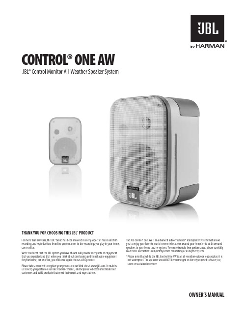
unPaCking The sYsTeMCarefully unpack the system. If you suspect damage from transit, report it immediately to your dealer and/or delivery service. Keep the shipping carton and packing materials for future use. Open the package and verify the following contents:inCluded2 JBL Control One AW speakers2 x wall-mount, rotatable brackets(includes bar wrench and backup cords)1 x Owner’s ManualPlaCing The sPeakersDetermine where to place the speakers. The following figures show two possible applications.Application 1: Adding surround speakers to a home theater system.Application 2: Adding speakers to remote locations in your home.Left Rear ChannelRight RearChannelCenter RearChannel45oCOnneCTing The sPeakersConnect the speaker wire (included) to the push terminals on the rear of the speaker (10).Please note that the speaker wire supplied features a polarity stripe to help distinguish its twoconductors. Use this polarity stripe to ensure that you are connecting the positive (+) terminal onthe JBL Control One AW speakers to the positive (+) terminal on the amplifier, and the negative(–) speaker terminal to the negative (–) speaker terminal. It does not matter whether you use thestriped conductor for connecting the postive (+) terminals or the negative (–) terminals.+–10wall and sTand PlaCeMenTAdjustable wall brackets are included for the JBL Control One AW speakers. The includedbrackets are for wall-mounting only. Ceiling-mounting of the JBL Control One AW speakers is notrecommended, regardless of the bracket used.wall-MOunTing The sPeakers using inCluded wall BraCkeTsiMPOrTanT saFeTY nOTe: Proper selection of mounting hardware not includedherein, and proper assembly and installation of brackets, in c luding, but not l imitedto, selection of appropriate weight-bearing support and bracket use with the specifiedspeaker only is the exclusive responsibility of the customer. Manufacturer disclaimsany l iability for the selection of mounting hardware and/or bracket installation.Left FrontChannel CenterChannel Right FrontChannelSubwooferLeft Surround ChannelRightSurroundChannelCouchLeft FrontChannelRight FrontChannel24wall-MOunTing The sPeakers using Third-ParTY wall BraCkeTsEach JBL Control One AW speaker contains a 1/4"-20 threaded insert on the back to facilitate the use of third-party wall brackets. Please consult your JBL dealer or distributor for recommendations.nOTe: Customer is responsible for proper selection and installation of appropriate third-party wall brackets.The threaded insert on the bottom of the speaker is not intended for wall-bracket attachment. It is provided for use with an appropriate third-party floor stand (see note below).sTand-MOunTing The sPeakersEach JBL Control One AW wireless speaker contains a 1/4"-20 threaded insert on the bottom to facilitate the use of third-party floor stands. Please consult your JBL dealer for recommendations.nOTe: Customer is responsible for proper selection and installation of appropriate third-party wall brackets and/or floor stands.MainTenanCe and serviCeThe speaker enclosures may be cleaned using a soft cloth to remove fingerprints or to wipe off dust.All wiring connections should be inspected and cleaned or remade periodically. The frequency of maintenance depends on the metals involved in the connections, atmospheric conditions and other factors, but once per year is the minimum.In the event that your system ever needs service, contact your local JBL dealer or distributor, or visit for a service center near you.sPeCiFiCaTiOnsFrequency range (±3dB):80Hz – 20kHz Power handling (peak/continuous):200 W/50 W Maximum recommended amplifier power*:100 W RMSLow-frequency driver:4" (100mm), magnetically shielded High-frequency driver:1/2" (12mm) titanium-laminate, magnetically shielded Sensitivity:87dB/2.83V/1m Nominal Impedance: 8 OhmsDimensions (H x W x D):9" x 6-1/8" x 5-1/2"(229mm x 156mm x 140mm)Weight:4.3 lb (2.0kg)Features, specifications and appearance are subject to change without notice.*The maximum recommended amplifier power rating will ensure proper system headroom to allow for occasional peaks. We do not recommend sustained operation at these maximum power levels.© 2011 HARMAN International Industries, Incorporated. All rights reserved.JBL is a trademark of HARMAN International Industries, Incorporated, registered in the United States and/or other countries.Features, specifications and appearance are subject to change without notice.HARMAN Consumer, Inc.8500 Balboa Boulevard, Northridge, CA 91329 USA。

The JBL Intonato 24 Monitor Management Tuning System provides easy setup, automated calibration and comprehensive control of professional control room monitoring systems. Housed in a 2U rack-mount enclosure, Intonato 24 precisely calibrates and controls a combination of 24 speakers configured as stereo, surround or immersive audio reference monitoring systems. You can create and instantly recall customized routings of a combination of analog, digital and networked audio sources. Included software and an optional Desktop Controller put the system’s powerful monitoring features at your fingertips. With included calibration mic and software app, Intonato 24 delivers the benefits of a precisely calibrated system, and takes control room monitoring to the next level.Intonato/Ĭntō’nătō/ (intonare) tuned pp., matched adj., in tune adj. The primary attribute of the ideal control room monitoring environment.COMPLETE, NEXT-GENERATION SYSTEMWhile the approach to control room monitoring has remained consistent over the years, the audio signal path and production workflow have evolved tremendously. The, JBL Intonato 24 and 7 Series Master Reference Monitors provide a complete next-generation system, empowering content creators to produce consistently superior output regardless of the spaces where they find themselves, or the formats they are asked to deliver. While JBL designed Intonato 24 as thehub of the JBL 7 Series installed reference monitor system,it can be used with any passive or powered speakers.A PRECISELY TUNED MONITORING ENVIRONMENTIntonato 24 includes our latest automated speaker calibration technology, which measures and automatically optimizes monitoring system response at the listening position. Using the supplied calibration microphone, and software app, the system precisely matches the level and time-of-arrival (delay) of each speaker while setting up to 12 filters per speakerto compensate for low-frequency anomalies related to the geometry and construction of the room. Eight additional user full-range EQ filters allow project-specific response curves and compensation for transmission loss when speakers are placed behind a perforated cinema screen.IMMERSIVE READY—THE MOST I/O IN ITS CLASSIntonato 24 comes standard with the most I/O in its class. With the connections and power to manage monitoring systems ofup to 24 speakers, Intonato 24 makes immersive monitoring a reality in existing control rooms. 24 analog, 24 AES3, and up to 256 networked input connections* enable you to use a broad range of equipment including analog and digital mixing consoles, work stations and playback sources. Intonato 24 features internal routing and a mixer to provide unprecedented monitoring flexibility. Any combination of up to 24 connected analog and digital sources can be patched, routed and selectively monitored via any of the connected speakers or headphone systems. You can also create, store and instantly recall customized down-mix configurations.* Intonato is Dante format compatible with the optional BSS BLUDAN interfaceKEY MESSAGES6Configurable monitoring in mono, stereo, surroundand immersive formats of up to 24 speakers24 analog, digital and network input sourcesInternal router/mixerallows user-configurable down mixes and routingsSave and recall project-specific monitoring configurations and speaker tuningsAutomated speaker calibration with included microphone Comprehensive bass management and subwoofer integrationIntuitive control with included Mac, Windows and tablet software* and optional Intonato Desktop Controller HIGHLIGHTS 6Intonato 24 shown with included microphone and optional Intonato Desktop ControllerMAC, WINDOWS, TABLET* SOFTWARE 6Intonato 24 software provides real-time control of System Volume, Mute and Dim controls, individual speaker Mute and Solo, input source and speaker selection, user-configured down-mixes and more. The software provides easy, intuitive setup and calibration of monitoring systems and input sources.A COMPLETE SOLUTION FOR ANY CONTROL ROOM 6Intonato 24 pairs with JBL 7 Series studio monitors to create the first complete monitoring system designed for immersive audio production in control rooms of any size. Intonato 24 includes tuning presets for JBL 7 Series Installed Monitors and M2 Master Reference Monitors, and can also be used with any passive or powered speakers. In addition, the HARMAN BLU link network protocol allows Intonato 24 to be digitally networked with Crown power amplifiers and a wide assortment of system components.* iOS and Android Tablet Software available summer 2017INTONATO 24 DESKTOP CONTROLLER 6In an elegant compact form factor, the optional Intonato Desktop Controller provides live control of the features needed during sessions. Instant recall of user-created Scenes allows down-mix monitoring and monitoring of selected sources via main and alternate speaker systems. The Desktop Controller is connected to Intonato 24 using a single CAT5cable and powered over Ethernet.CROWN DCI 8|300NINTONATO 24ANALOG OR DIGITAL INPUT SIGNALSControl using Computer, Tablet and Intonato Desktop ControllerFULL FEATURES AND BENEFITS 6• Intonato 24 can be used withany studio monitors• 24 balanced analog line-level speaker outputs allow connection of powered studio monitors and power amplifiers • Automated Speaker Calibration with included microphone precisely balances, tunes and aligns all speakers to deliver greater accuracy to the mix position in any room • 12 bands of Room EQ, Delay and Level per speaker • 8-band User EQ allows standard and customized response curves, such as X-Curve, and compensation for perforated screen transmission loss • 24 balanced analog inputs withselectable input sensitivity and gain trims allow connection to a broad range of professional and consumer equipment • 24 AES3 Inputs, 8 Sample-Rate Converters, and Word Clock Input allow connection of a broad range of digital sources • RJ45 BLU link port allows convenient CAT5 connection to Crown power amplifiers and other HARMAN BLU link equipped devices; optional BSS BLUDAN interfaceconnects Intonato 24 to Dante networks • Input gain trim controls and level indicators on each channel allow precise calibration • Internal router/mixer allows user-configurable down-mixes and selective monitoring of any input via any or all speakers • Integration of up to 4 subwoofers for LFE channels and bass management • Variable Audio/Video Sync delay allows compensation for video display latency • Stereo Aux Out with dedicated level control, EQ and talk back systemallows an independent feed to be sent to talent or a remote “green room” • Scenes allow instant recall of down-mixes, input source and speaker selection • Profiles allow configurations and project-specific EQ to be saved and recalled • Intuitive setup and control with included Macintosh, Windows and iOS/Android tablet software or optional Intonato Desktop Controller • Low-noise fan for quiet operationSPECIFICATIONS 6OUTPUTSTotal Simultaneous Outputs: 24 analog outputs and 24 simultaneous BLU link outputs Connectors: 3 female 25-pin D-Sub connectors 24 Balanced ANALOG OUTPUTS: Female XLRMax Output Level: +24 dBu, balanced, ≤ .006% THD BLU LINK AUDIOConnectors: 2 x RJ45 connectors Maximum Cable Length: 100m/328ft on Category 5e or higher cable between devices Latency: 11/Fs [0.23ms@48k, 0.11ms@96k]Pass Through Latency: 4/Fs [0.08ms@48k, 0.04ms@96k] INPUTSTotal Simultaneous Inputs: 24(selectable among the available 24 analog, 24 AES3, and 24 BLU link input channels)ANALOG INPUTSConnectors: 3 female 25-pin D-Sub connectorsType: Electronically balanced, RF filtered Impedance: > 48 kΩ balanced, > 24 kΩ unbalancedInput Sensitivity: Selectable in software per D-Sub connector: -10 dBV with 18 dB of headroom, +4 dBu with 20 dB of headroom, +8 dBu with 24 dB of headroom Max Input Level: +28 dBu, ≤0.008% THD CMRR: > 47 dB @ 1 kHz 24 AES3 DIGITAL INPUTS 8 Sample Rate Conversion: selectable in software1 Calibration MIC / Talk back Mic INPUT With Phantom Power: +48 VDCWORD CLOCK INPUTSupported Sample Rates: 44.1 kHz, 48 kHz, 88.2 kHz, 96 kHz Tolerance: ±50 ppm maxSYSTEM PERFORMANCE A/D Converter: 24-bitA/D Dynamic Range: 114 dB A-weighted D/A Converter: 24-bitD/A Dynamic Range: 115 dB A-weighted Internal Processing Word Length: 32-bit floating pointSupported Sample Rates: 44.1 kHz, 48 kHz, 88.2 kHz, 96 kHz; 32-192 kHz, sample-rate convertors enabled.Dynamic Range: 114 dB A-weighted; 112 dB unweightedTHD+Noise: 0.007% typical at +4 dBu, 1 kHz, 0 dB input gain Frequency Response: 20 Hz – 20 kHz, +0 /- 0.5 dBLatency: Analog IN to analog OUT (96 kHz): 2.28 msAES IN to analog OUT (96 kHz): 2.15 ms BLU link input to BLU link output (96 kHz): 0.04msSIGNAL PROCESSING Included Speaker Tuning Presets: JBL 705i, 708i, M2User EQ: 8-band fully parametric EQ w/ selectable filter typeRoom EQ: 12-band fully parametric EQ Bass Management Crossover: VariableSpeaker Output Delay: Up to 18 ms per output channel for speaker time-of-arrival offset)A/V Synchronization Delay: Up to 150 ms (globally applied to all output channels except aux outputs)Aux Out Delay: Up to 150 msMaster Volume Control: -120 dB to 0 dB Dim Control: User-adjustable, -120 dB to 0 dBPOWER SUPPLYType: Universal switch-modeOperating Voltage: 100-240 VAC, 50/60 Hz Power Consumption: 85 WattsPHYSICALRack Height: 2UUnit Weight: 14.30 lbs (6.4kg)Shipping Weight: 19.04 lbs. (8.64 kg)Dimensions: 3.5” (H) x 13.75” (D) x 19.0” (W)88.9mm (H) 349.25mm (D) x 482.6mm (W)Order SKU: INTONATO24MX UPC 691991006197RECOMMENDED AUDIO CABLES (not included)Analog In/Out DB25 (Female); AES In DB25 (Female)Wired according to industry-standard TASCAM DB25 pinoutINCLUDED ITEMSPower Cords: 1 ea. US and 1 ea. European (SHUKO-plug)Operation Manual and Setup Guide Calibration MicrophoneSet Up and Control Software (via download)OPTIONAL ACCESSORIES:Intonato Desktop Controller Unit Weight: 1.0 lbs (0.45 kg)Dimensions: 2.84” (H) x 6.73” (D) x 4.70” (W) 72.0mm (H) 117.0mm (D) x 119.4mm (W)Shipping Weight: 1.7 lbs (0.76 kg) Shipping Carton dimensions: 8.75” L x 7” W x 5.75” H ( 222.25 mm L x 177.8 mm W x 146 mm H)Order SKU: INTONATO-DC-M UPC 691991006203Monitor Management T uning SystemINTONA TO | 24© 2017 HARMAN International Industries, Incorporated. All rights reserved. AKG is a trademark of AKG Acoustics GmbH, registered in the United States and /or other countries. Features, specifications and appearance are subject to change without notice.JBL Professional 8500 Balboa Blvd. Northridge, CA 91329 USAComplete Specifications are available in the Intonato 24 Operation Manual at /intonato。
全景声录音棚解决方案【系统概述】全景声录音棚系统,是一套建立在三维声场空间的音频系统解决方案,以Pro Tools Ultimate软件平台、Dobly Atmos声场技术、苹果 Mac Pro,创音音频电脑、DSD多通道音频接口、以及全景声音箱系统构成,在环境方面是以全景声声场而设计的专业声学空间。
全景声音乐录音棚系统是建立7.2.4 的3D音箱系统上,通过 TREAIN 音频工作站,以及Pro Tools 软件,以及DSD 88 V2 音频接口,完成32轨的实时录音与回放,768个音频轨的全景声混音,通过 Dobly Atmos Production Suit,可以渲染出Dobly标准的音频格式,在两台电脑上,通过内嵌的 Dobly Bridge 可以桥架宿主Pro Tools ,直接可以完成音箱定位与返送监听。
构建全景声的系统,除了设备要求,使用环境还需要进行专业声学设计,并构建全景声声场。
全景声录音棚的声学特性对于录音制作及其制品的质量起着十分重要的作用。
人们可以根据需要对其进行分类,例如,可以按声场的基本特点划分而分为自然混响录音棚、强吸声(短混响)录音棚以及活跃端、寂静端(LEDE)型全景声录音棚,也可以从用途角度划分而分为对白录音室、音乐全景声录音室、全景声混合录音室等。
【系统构建】全景声录音棚系统的构建,我们推荐是以业界标准的 Pro Tools软件系统和杜比全景声为基础构建,紧密整合高质量的音频硬件,以及杜比认证的全景声监听音箱,为您打造无与伦比的全景声音频系统。
全景声录音棚由录音室和控制室两部分组成;控制室用于采录编全过程的操作和控制,兼作后期节目制作。
杜比全景声录音棚设备系统主要包括以下几点:专业音频工作站,音频处理系统,声道管理系统,监听系统,拾音系统,编曲系统,后期系统及其他周边备等。
一,专业音频工作站系统PC音频工作站电脑系统 Tower 900软件音频工作站录制回放系统 ProTools Felx二,音频处理系统DSD 音频转换器 DSD 88 V2 IO 杜比全景声(Dolby Atmos)渲染器 Dolby Atmo 三,音频管理系统沉浸式多声道管理系统 D-MON 多声道管理系统24通道监控管理系统 JBL Intonato 24四,拾音系统电子管麦克风 GA-47 MKII动圈麦克风 SM58A话筒放大器 PRE-73 DLX Premier五,监听系统前方主监听音箱 KLASIK 2020前方低音监听音箱 Aeon 2 Bass Extenders 中置音箱 Atmos system 7.2.4天空环绕音箱 APS Aeon 2 Black六,编曲系统编曲工作站 CUBASE 12 PROMIDI键盘 NI KOMPLETE KONTROL 【系统优势】杜比全景声系统音频解决方案,搭载杜比的全景声音箱系统能够帮助您创建、编辑、混音和交付最优质的音频,管理复杂的工程和海量数字资产,提高工作效率,领先他人一步。
/specialtyaudio 一直为全球各地的音乐厅、录音棚和电影院提供音频设备,已成为深受领先的唱片艺术家和录音师们信任的品牌。
演播监听扬声器系列的新成员。
要使系统发3.背面面板概览A BCD E FA XLR / ¼" 平衡输入灵敏度选择 – 选项包括 -10dB (高灵敏度模式)和 +4dB (低灵敏度/保护输入前端,避免过载) K 低音轮廓开关: 用于调整边界补偿B 左右 XLR / ¼" 平衡输入L 低音炮输出:使用低音炮时,系统会激活一个 80Hz 高通滤波器C 以太网:连接至路由器的可用端口,进行有线网络方式的流媒体播放M 主扬声器数字链接:使用 CAT5e 或更高级的电缆(最长 6m )在主和副扬声器之间建立有线连接D USB-A + 维护按钮:仅用于维护/固件更新(不可用于音频或 USB 充电)N L/R 分配选择器:根据主扬声器的摆放位置以选择 L (左)或 R (右)E 重置:出厂设置 – 按住直到前面板上的指示灯开始闪烁O 主扬声器电源开关 -F 主扬声器同步按钮:用于以无线方式连接至副扬声器P 副扬声器同步按钮:用于以无线方式连接至主扬声器G 主扬声器 IEC 电源连接 – 配备一个通用电源,以便在国内和其他国家/地区使用这些扬声器。
Q 副扬声器数字链接:使用 CAT5e 或更高级的电缆(最长 6m )在主和副扬声器之间建立有线连接H 3.5mm 模拟立体声输入R 副扬声器 IEC 电源连接 - 配备一个通用电源,以便在国内和其他国家/地区使用这些扬声器。
I Toslink /光纤数字输入S副扬声器电源开关JUSB-B 数字直接 PCM 输入4.一般摆放/设置室内摆放每个扬声器的摆放位置应与位于顶部的高音扬声器互相垂直。
摆放扬声器时,应确保收听位置和两个扬声器能够形成一个等边三角形。
根据扬声器到各侧边界(如墙壁、书柜内/储藏柜内、或地板支架上)的距离,以设置主扬声器背面的低音增益开关。
2READ FIRST! Important Safety Precautions!1.Read these instructions.2.Keep these instructions.3.Heed all warnings.4.Follow all instructions.5.Do not use this apparatus near water.6.Clean only with a dry cloth.7.Do not block any ventilation openings. Install in accordance with the manufacturer’s instructions.8.Do not install near any heat sources such as radiators, heat registers, stoves or other apparatus (including amplifiers) that produce heat.9.Do not defeat the safety purpose of the polarized or grounding-type plug.A polarized plug has two blades with one wider than the other.A grounding-type plug has two blades and a third grounding prong. The wide blade or the third prong are provided for your safety. If the provided plug does not fit into your outlet, consult an electrician for replacement of the obsolete outlet.10.Protect the power cord from being walked on or pinched, particularly at plugs, convenience receptacles and the point where they exit from the apparatus.11.Only use attachments/accessories specified by the e only with the cart, stand,tripod, bracket or table specified by the manufacturer or sold with thecaution when moving the cart/ apparatus combination to avoid injury from tip-over.13.Unplug this apparatus during lightning storms or when unused for long periods of time.14.Refer all servicing to qualified service personnel. Servicing is required when the apparatus has been damaged in any way, such as power-supply cord or plug isdamaged, liquid has been spilled or objects have fallen into theapparatus, the apparatus has been exposed to rain or moisture, does not operate normally, or has been dropped.15.Do not use attachments not recommended by the product manufacturer, as they may cause hazards.16.This product should be operated only from the type of power source indicated on the marking label. If you are not sure of the type of power supply to your home, consult your product dealer or local power company. For products intended to operate from battery power or other sources, refer to the operating instructions.17.If an outside antenna or cable system is connected to the product, be sure the antenna or cable system is grounded so as to provide some protection against voltage surges and built-up static charges. Article 810 of the National Electrical Code,ANSI/NFPA 70, provides information with regard to proper grounding of the mast and supporting structure,grounding of the lead-in wire to an antenna discharge unit, size of grounding conductors, location of antennadischarge unit, connection to grounding electrodes, and requirements for the grounding electrode. See Figure A.18.An outside antenna system should not be located in the vicinity of overhead power lines or other electric light or power circuits, or where it can fall into such power lines or circuits. When installing an outside antenna system, extreme care should be taken to keep from touching such power lines or circuits,as contact with them might be fatal.19.Do not overload wall outlets,extension cords, or integralconvenience receptacles, as this can result in a risk of fire or electric shock.20.Never push objects of any kind into this product through openings, as they may touch dangerous voltage points or short-out parts, which could result in a fire or electric shock.Never spill liquid of any kind on the product.21.The apparatus shall not be exposed to dripping or splashing, and no objects filled with liquids,such as vases, shall be placed on the apparatus.22.Do not attempt to service this product yourself, as opening or removing covers may expose you to dangerous voltage or other hazards.Refer all servicing to qualified service personnel.23.When replacement parts are required, be sure the service technician has used replacement parts specified by the manufacturer or that have the same characteristics as the original part. Unauthorized substitutions may result in fire,electric shock or other hazards.24.Upon completion of any service or repairs to this product, ask the service technician to perform safety checks to determine that the product is in proper operating condition.25.The product should be mounted to a wall or ceiling only asrecommended by the manufacturer.THANK YOU FOR CHOOSING JBLFor more than 60years, JBL has been involved in every aspect of music and film recording and reproduction, from live performances to the provide every note ofenjoyment that you expect –and that when you think aboutpurchasing additional audioequipment for your home, carWeb site at .It enables us to keep youposted on our latest advance-ments, and helps us to betterunderstand our customers4SPEAKER PLACEMENTSUBWOOFERSURROUND SPEAKERSFRONTSPEAKERSThe front speakers should be placed the same distance from each other as they are from the listening position.The CSB5 speakers should be placed at about the same height from the floor as the listeners’ ears will be, or they may be angled toward the listeners.The center channel speaker should be placed slightly behind the front left and right speakers, and no more than 2 feet (0.6m) above or below the tweeters of the left and right speakers. It is often convenient to set the center speaker on top of thetelevision set, as shown in the drawing.The JBL Cinema Soundspeaker system may be used in 5.1-, 6.1- or 7.1-channel applications. In 5.1-channel applications, two of thesurround speakers should be placed slightly behind the listening position and, ideally,should face each other and be at a level higher than the listeners’ ears. If that is not possible, they may be placed against a wall behind the listening position, facingforward. In 6.1-channel appli-cations, two of the surround speakers should be placed in the side positions, and asingle surround back speaker should be placed against the wall behind the listening position. In 7.1-channelapplications, place two of the surround speakers in the side positions, and place the two surround back speakers against the rear wall.In Dolby ®Digital and DTS ®systems, it is best to aim all of the speakers (except the subwoofer) toward thelistening position at or slightly above about ear-level height.In systems where only analog surround processing (such as Dolby Pro Logic ®II) isavailable, it may be preferable to aim the speakers straight out from the wall to obtain a more diffuse sound.The low-frequency material reproduced by the subwoofer is mostly omnidirectional, and this speaker may be placed in a convenient location in the room. However, bass reproduction will be maximized when the subwoofer is placed in acorner along the same wall as the front speakers.Experiment with subwoofer placement by temporarily placing the subwoofer in the listening position and moving around the room until the bass reproduction is best. Place the subwoofer in that location.CENTER CHANNEL SPEAKER† Single surround back speaker may be used with 6.1 receivers and processors.Alternate placement for surround speakers when only 5.1 channels are used; required placement for surround back speakers in 7.1-channel systems.5The CSC55 center channel and the CSB5 are designed to be mounted on the wall. There are two (2) fixed-mount wall brackets provided for the CSC55, and one for the CSB5.Each speaker bracket will require up to three 1-1/2" #10wood screws; each screw should be fastened to a wall stud.If a wall stud is unavailable,install an anchor appropriate for a 1-1/2" #10 screw.NOTE: The customer is responsible for the correct selection and use of mounting hardware (available through hardware stores) to ensure the proper and safe wall-mounting of the speakers.Step ing the included mounting template (CSC55only) or the bracket back plate (CSB5 only), mark thepositions on the wall where you would like to place the mounting screws.Step 2.Attach the back plate(s) of the bracket to the wall using three screws (not included).Step 3.Attach the frontplate(s) (with the two holes) of the bracket(s) to the CSC55 or CSB5, using the provided screws.Step 4.Slide the CSC55 or CSB5 speaker with attached bracket front plate(s) onto the back plate(s) of the bracket(s).Once positioned properly, the speaker should slide down slightly and become secure.To remove the speaker from the wall, simply slide the speaker up.WALL-MOUNTING THE CSC55AND CSB56CONNECTION TIPSSPEAKER CONNECTIONSSeparate and strip the ends of the speaker wire as shown.Speakers and electronics terminals have corresponding (+) and (–) terminals. Most manufacturers of speakers and electronics, including JBL, use red to denote the (+)terminal and black to denote the (–) terminal.The (+) lead of the speaker wire is noted with a stripe. It is important to connect both speakers identically:(+) on the speaker to (+) on the amplifier and (–) on the speaker to (–) on the amplifier.Wiring “out of phase” results in thin sound, weak bass and a poor stereo image.With the advent of multichan-nel surround sound systems,connecting all of the speakers in your system with the correct polarity remains equally important in order to preserve the proper ambience and directionality of theprogram material.insert each wire into its corresponding hole in the base. Then tighten down the terminals.CSB5,CSC55To use the binding-post speaker terminals, unscrew the colored collar until the pass-through hole in the center post is visible under the collar. Insert the bare end of the wire through this hole;then screw the collar down until the connection is tight.The hole in the center of each collar is intended for use with banana-type connectors. To comply with European CE certification,these holes are blocked with plastic inserts at the point of manufacture.To use banana-type connectors requires the removal of the inserts.The hole in the center of each collar is intended for use with banana-type connectors. To comply with European CE certification,these holes are blocked with plastic inserts at the point of manufacture.To use banana-type connectors requires the removal of the inserts.DOLBY PRO LOGIC®(NON-DIGITAL) – LINE LEVELUse this installation method for Dolby Pro Logic applications (not Dolby Digital, DTS or other digital processing), where the receiver/processor is equipped with a subwoofer output, or a volumecontrolled preamp (line-) level output:Use RCA-type interconnectsto connect the line-levelsubwoofer outputs on yourreceiver or amplifier to theline-level inputs on thesubwoofer. IMPORTANT: Donot use the LFE input on thesubwoofer with DolbyPro Logic processors.NOTE: If your receiver oramplifier has only onesubwoofer output jack, thenyou will need to use aY-connector (not included).Plug the male end of theY-connector into your receiveror amplifier’s subwooferoutput jack, and connect eachof the two female ends toseparate RCA-typeinterconnects. Finally, plug theRCA-type interconnects intothe line-level inputs on thesubwoofer.Connect each speaker tothe corresponding speakerterminals on your receiveror amplifier.Make sure your receiver orprocessor is correctlyconfigured to indicate that thesubwoofer is “On.”Use this installation method for Dolby Digital, DTS or other digital surround processors: Use the line-level input jack marked “LFE” for the Low-Frequency Effects channel.Connect this jack to the LFEoutput or subwoofer outputon your receiver or amplifier.Connect each speaker tothe corresponding speakerterminals on your receiveror amplifier.Make sure that you haveconfigured your surroundsound processor for “Sub-woofer On.” Also configureyour receiver for 5.1-, 6.1-or 7.1-channel operation asappropriate. The front left,front right, center and rearspeakers should all be setto “Small.” If your receiverallows you to set the cross-over frequency between thesubwoofer and the mainspeakers, select 100Hz orthe setting that is the closestfrequency below it.DOLBY®DIGITAL OR DTS®(OR OTHER DIGITAL SURROUND MODE) CONNECTION7SUBWOOFER OPERATIONPress the Master Power switch (marked “Power” a) to the On position to use the subwoofer. The CSS10 subwoofer will automatically turn on or go into standby (sleep) mode as described below. When your receiver or amplifier is off, or is not sending program materialto the subwoofer, the subwoofer will be in standby mode (the LED on the front of the CSS10 will be red). When the subwoofer senses an audio signal, it will automatically turn on (the LED will be green). If the subwoofer does not sense a signal after approximately 20 minutes, it will automatically go into standby mode.If you will be away from home for an extended period of time,or if the subwoofer will not beused, switch the MasterPower switch a to the Offposition by pressing it until itpops out.VOLUMEVolume may be adjusted using the Subwoofer Level control b, as shown.The Phase control determineswhether the subwoofer’spistonlike action moves in andout in phase with the mainspeakers or opposite the mainspeakers. There is no corrector incorrect setting. Properphase adjustment depends onseveral variables, such assubwoofer placement andlistener position. Adjust thePhase switch c to maximizebass output at the listeningposition.Remember, every system,room and listener is different.There are no right or wrongsettings; this switch offers theadded flexibility to adjust yoursubwoofer for optimumperformance for your specificlistening conditions withouthaving to move your speakers.If at some time in the futureyou happen to rearrange yourlistening room and move yourspeakers, you shouldexperiment with the phaseswitch in both positions, andleave it in the position thatmaximizes bass performance.8If there is no sound from any of the speakers:• Check that receiver/amplifier is on and a source is playing.• Check that the powered subwoofer is plugged in and is turned on (Power switch a pushed in).• Check all wires and connections between receiver/ amplifier and speakers. Make sure all wires are connected. Make sure none of the speaker wires are frayed, cut or punctured, or touching each other.• Review proper operation of your receiver/amplifier.If there is no sound coming from one speaker:• Check the “Balance” control on your receiver/amplifier.• Check all wires and connections between receiver/ amplifier and speakers. Make sure all wires are connected. Make sure none of the speaker wires are frayed, cut or punctured, or touching each other.• In Dolby Digital or DTS modes, make sure that the receiver/ amplifier is configured so that the speaker in question is enabled.• Turn off all electronics and switch the speaker in question with one of the other speakers that is working correctly. Turn everything back on, and determine whether the problem has followed the speaker or has remained in the same channel. If the problem is in the same channel, the source of the problem is most likely with your receiver or amplifier, and you should consult the owner’s manual for that product for further information. If the problem has followed the speaker, consult your dealer for further assistance or, if that is not possible, visit .If there is no sound from thecenter speaker:• Check all wires andconnections between receiver/amplifier and speaker. Makesure all wires are connected.Make sure none of the speakerwires are frayed, cut orpunctured, or touching eachother.• If your receiver/processor isset in Dolby Pro Logic mode,make sure the center speaker isnot in phantom mode.• If your receiver/processor isset in one of the Dolby Digital orDTS modes, make sure thereceiver/processor isconfigured so that the centerspeaker is enabled.If the system plays at lowvolumes but shuts off asvolume is increased:• Check all wires andconnections between receiver/processor and speakers. Makesure all wires are connected.Make sure none of the speakerwires are frayed, cut orpunctured, or touching eachother.• If more than one pair of mainspeakers is being used, checkthe minimum impedancerequirements of your receiver/amplifier.If there is low (or no) bassoutput:• Make sure the connections tothe left and right “SpeakerInputs” have the correctpolarity (+ and –).• Make sure the subwoofer isplugged into an active electricaloutlet and is turned on (Powerswitch a pushed in).• In Dolby Digital or DTS modes,make sure your receiver/processor is configured so thatthe subwoofer and LFE outputare enabled.• Switch the Phase switch c tothe opposite position, and selectthe position that results in themost pleasing bass response.If there is no sound fromthe surround speakers:• Check all wires andconnections between receiver/processor and speakers. Makesure all wires are connected.Make sure none of the speakerwires are frayed, cut orpunctured, or touching eachother.• Review proper operation ofyour receiver/amplifier and itssurround sound features.• Make sure the movie orTV show you are watchingis recorded in a surround soundmode. If it is not, check to seewhether your receiver/processor has other surroundmodes you may use.• In Dolby Digital or DTS modes,make sure your receiver/processor is configured so thatthe surround speakers areenabled. When five satellitesare in use, remember toconfigure your receiver orprocessor for 6.1-channeloperation, and when sixsatellites are in use, configureyour receiver or processor for7.1 channels.• Review the operation of yourDVD player and the jacket ofyour DVD to make sure that theDVD features the desired DolbyDigital or DTS mode, and thatyou have properly selected thatmode using both the DVDplayer’s menu and the DVDdisc‘s menu.TROUBLESHOOTING9SYSTEMFrequency Response 27Hz – 30kHz (–6dB)CST55Maximum Recommended Amplifier Power150 Watts*Power Handling50W Continuous/300W Peak Frequency Response55Hz – 30kHz (–6dB) Nominal Impedance8 OhmsSensitivity90dB @ 1 Watt/1 meterTweeter One 3/4" (19mm) titanium-laminate dome, video-shieldedWoofers Dual 130mm (5")transducers with PolyPlas™ cones, neodymium magnets and HeatScape™ motor structure, video-shielded Dimensions (H x W x D)(including wall-mount bracket and grille)1168 x 286 x 286mm (46" x 11-1/4" x 11-1/4") Weight7.7kg (17 lb)CSB5Maximum Recommended Amplifier Power125 Watts*Power Handling40W continuous/300W peak Frequency Response60Hz – 30kHz (–6dB) Nominal Impedance8 OhmsSensitivity88dB @ 1 watt/1 meterTweeter 3/4" (19mm) Titanium-laminate dome, video-shieldedWoofer5" (130mm)Transducer with PolyPlas™cone, neodymium magnet and HeatScape™ motor structure, video-shieldedDimensions (H x W x D) (including base and grille) 363 x 155 x 116mm (14-5/16" x 6-1/8" x 4-9/16") Weight2.3kg (5 lb)Dimensions (H x W x D)(without base and with wall-mount bracket and grille)338 x 155 x 130mm (13-5/16" x 6-1/8" x 5-1/8") Weight2kg (4.5 lb) CSC55Maximum Recommended Amplifier Power150 Watts*Power Handling50W Continuous/300W Peak Frequency Response55Hz – 30kHz (–6dB) Nominal Impedance8 OhmsSensitivity90dB @ 1 watt/1 meterTweeter One 19mm (3/4")titanium-laminate dome, video-shieldedWoofers Dual 130mm (5")transducers with PolyPlas™ cones, neodymium magnets and HeatScape™ motor structure, video-shielded Dimensions (H x W x D)(including wall-mount bracket and grille)159 x 667 x 108mm (6-1/4" x 26-1/4" x 4-1/4") Weight4.5kg (10 lb)CSS10Amplifier Power150 Watts RMSFrequency Response27Hz – Low-pass crossover setting at signal sourceLow-Frequency Driver250mm (10")cone and HeatScape™motor structure, video-shieldedInput LFE preamp levelDimensions (H x W x D)(including feet)464 x 337 x 406mm (18-1/4" x 13-1/4" x 16") Weight19.5kg (43 lb)SPECIFICATIONSAll features and specifications are subject to changewithout notice.Dolby and Pro Logic are registered trademarks of DolbyLaboratories.DTS is a registered trademark of DTS, Inc.*The maximum recommended amplifier power ratingwill ensure proper system headroom to allow foroccasional peaks.We do not recommend sustained operation at thesemaximum power levels.CSB5, CSC55 and CST55CSS10 (230V only)。
GUIA DEL PROPIETARIOESPAÑOL2INCLUYEPlantilla / pieza pintada.Un par de altavoces con rejilla.GRACIAS POR ELEGIR JBLHTI6,HTI8HTI6CDurante más de 50 años, JBL ha jugado un papel importante en cada uno de los aspectos en los procesos de grabación y reproducción de música y películas, desde actuaciones en directo hasta reproduccio-nes en el estudio, en su casa o en la oficina.Estamos seguros de que los altavoces JBL que ha elegido le proporcionarán toda la satis-facción sonora que espera de ellos, y de que cuando necesite adquirir algún equipo de audio adicional para su casa, su coche o su oficina, volverá a elegir JBL.Tómese un momento para registrar su producto en la página web . Nos permitirá mantenerle informado de nuestras más recientes novedades, y nos ayudará a entenderle mejor y a fabricar productos de acuerdo con sus deseos y necesidades. JBL Consumer ProductsHTI55Altavoz con rejilla. El logo se colocará en la rejilla depen-diendo de su instalación verti-cal u horizontal.Plantilla / pieza pintada.3ALTAVOCES FRONTALES (HTI6,HTI8,HTI55)MODELOS HTI6,HTI8 Y HTI55 COMO ALTAVOCES TRASEROSMODELOS HTI6C EN EL TECHOUBICACION DEL ALTAVOZUna adecuada ubicación de los altavoces es un paso importan-te para conseguir una repro-ducción sonora eficiente. Las siguientes recomendaciones tratan sobre cómo conseguir una adecuada colocación de los altavoces. Utilícelas como una guía. Pequeñas variacio-nes no modificarán la calidad de escucha. Los altavoces fron-tales deberán guardar entre ellos la misma distancia que guardan respecto a la posición de escucha. También deberán colocarse aproximadamente a la misma altura en que seencuentran la posición de escucha, con los altavoces de agudos en línea con los oídos del usuario.El modelo HTI55 es adecuado para las posiciones frontales izquierda, central y derecha.También puede ser utilizado como altavoz surround lateral o trasero. Se puede colocar tanto horizontalmente como vertical-mente, pero asegúrese de que los instala de manera que todos los altavoces de agudos de los altavoces frontales quedan a la misma altura (o no difieren en su posición en más de 60 centí-metros). Puede hacer girar el altavoz de agudos para colocar el logo de JBL en su posición correcta.En una configuración de cine doméstico, los dos altavoces surround deberán colocarse ligeramente por detrás de la posición de escucha, apuntán-dose entre ellos y ligeramente más altos que la posición de escucha. Si esto no es posible,deberá colocarlos en la pared (o en el techo), por detrás de la posición de escucha, mirando hacia adelante.En los sistemas de 6.1 y 7.1canales deberá colocar los altavoces surround traseros en la pared trasera. Los altavoces surround no deben tener un papel protagonista. Deberán proporcionar un sonido de ambiente difuso que acompaña al material de programa princi-pal que sale de los altavoces frontales. En los sistemas Dolby Digital y DTS ®, deberá dirigir los altavoces de agudos hacia la posición de escucha, a la altura de posición de escucha.E S P A ÑO L4Destornillador Phillips #2Cinta métrica CúterLápizde burbujaDestornilladorHERRAMIENTAS NECESARIASLa serie de altavoces de pared JBL HTI ha sido diseñada para una instalación fácil. Aún así, si usted no se ve capaz de instalar correctamente los altavoces, no dude en contac-tar con su distribuidor o con un instalador profesional.INSTALACIONLa mayoría de fabricantes de altavoces y de electrónica,incluyendo JBL, utilizan el color rojo para simbolizar el terminal positivo y el color negro para representar el terminal nega-tivo (-). Es importante conectar los altavoces de manera idén-tica: el símbolo (+) del altavoz con el símbolo (+) del amplifica-dor, y el símbolo (-) del altavoz con el símbolo (-) del amplifica-dor. Una conexión en contra-fase provocaría un sonido débil, con deficiencia en los graves y con una imagen esté-reo muy pobre. En los sistemas de sonido surround multicanal,la correcta polaridad continua siendo de vital importancia para conservar la buena repro-ducción y la direccionalidad del material sonoro.LONGITUD DE CABLE TAMAÑO RECOMENDADOHasta 6 metros.calibre 16 Hasta 9 metros. calibre 12Más de 9 metros. calibre 10Los cables de altavoz deberán tener la misma longitud. Si uno de los altavoces se encuentra más cercano al amplificador que otro, esconda el cable sobrante. Los altavoces y los terminales tienen su polaridad (+) y (-) correspondiente.CONEXIONES DE LOS ALTAVOCES5HTI6,HTI8,HTI55INSTALACION EXISTENTERetire la rejilla del marco del altavoz tirando de la lengüeta de papel. En caso de no encon-trar la lengüeta, y para evitar rayar la rejilla o el altavoz,introduzca la punta de un clip a través de uno de los agujeros de la rejilla y tire suavemente de él hasta separar la rejilla delaltavoz.Determine la ubicación correcta del altavoz.Nota:Retire la plantilla interior,que es la pieza pintada, y utilice la plantilla exterior al cortar.El procedimiento de colocación es el mismo para el altavoz HTI55, que también se puede colocar horizontal o vertical-mente.Realice el corte.Conecte los cables al altavoz.Vuelva a colocar la rejilla metálica. Tan sólo en el HTI55,coloque el logo de JBL sobre la rejilla según su posición sea horizontal o vertical.Coloque la pieza en la pared.Atornille cada uno de los cua-tro (seis para el HTI55)tornillos Phillips. Las piezas de anclaje se colocarán en su sitio y asegurarán la unidad a la pared.Los altavoces de la serie HTI incorporan unas piezas girato-rias únicas para los altavoces de agudos, que le permitirán apuntar las frecuencias agu-das, más direccionales, hacia la posición de escucha y a la altura de los oídos del usuario.Antes de instalar la rejilla del altavoz, presione ligeramente sobre la parte exterior del alta-voz de agudos para dejarlo en su posición ideal. El altavoz puede girar un máximo de 15 grados en cualquier direc-ción. No intente forzarlo para conseguir más movimiento.También puede girar el altavoz de agudos para orientar el logo JBL como desee.6HTI6CEXISTING CONSTRUCTIONRetire la rejilla del marco del al-tavoz tirando de la lengüeta de papel. En caso de no encontrar la lengüeta, y para evitar rayar la rejilla o el altavoz, introduzca la punta de un clip a través de uno de los agujeros de la rejilla y tire suavemente de él hasta separar la rejilla del altavoz.de la pared y el altavoz, de manera que las piezasgiratorias puedan realizar su recorrido.Conecte los cables al altavoz. Coloque la pieza en la pared.Atornille cada uno de los tres tornillos s piezas de anclaje se colocarán en su sitio y asegurarán la unidad a la pared.Vuelva a colocar la rejilla metálica.que es la pieza pintada, y utilice la plantilla exterior al cortar.Los altavoces de la HTI incorpo-ran unas piezas giratorias para los altavoces de agudos únicas,que le permitirán apuntar las frecuencias agudas, más direc-cionales, hacia la posición de escucha y a la altura de los oídos del usuario. Antes de ins-talar la rejilla del altavoz, pre-sione ligeramente sobre la parte exterior del altavoz de agudos para dejarlo en su posición ideal. El altavoz puede girar un máximo de 15 grados en cual-quier dirección. No intente for-zarlo para conseguir más movi-miento. También puede girar el altavoz de agudos para orientar el logo JBL como desee.INSTALACION NUEVAPINTAR EL MARCO Y LA REJILLA DEL ALT AVOZLos altavoces de la serie JBL HTI se pueden pintar para adaptarse a cualquier decora-ción. SI desea cambiar el color de la rejilla, su acabado sati-nado le sirve como primera capa. Antes de pintar, instale la pieza interior del kit de ensam-blaje dentro del altavoz. Esto protejerá los componenteselectrónicos del altavoz de lapintura y sus componentesresiduales. Utilice pintura enspray de calidad, y aplique unacapa delgada de color.Asegúrese de que los agujerosde la rejilla quedan libres depintura. Si los rellena con pin-tura disminuirá la calidadsonora en la reproducción.Nota: Retire con cuidado laespuma acústica de la rejillaantes de pintar. Colóquela denuevo una vez que la pintura dela rejilla se haya secado.Deberá elegir el marco correcto para su modelo de altavoz:MODELO DE ALTAVOZ MARCOHTI6RIF6HTI8RIF8HTI55RIF55HTI6C RIF6CGUIA DE SOLUCION DE PROBLEMASSI NO HA Y SONIDO EN NINGUNO DE LOS AL TA-VOCES:• Compruebe que el receptor / amplificador está activado y que existe una fuente en repro-ducción.• Compruebe todos los cables y las conexiones entre el recep-tor / amplificador y laos altavo-ces. Asegúrese de que todos los cables están conectados. Asegúrese de que ninguno de los cables está cortado odañado, y de que los cables no se tocan entre ellos.• Compruebe que su receptor / amplificador funciona correcta-mente.SI NO HA Y SONIDO EN UNO DE LOS DOSAL TAVOCES:• Comprebe el control de balan-ce en su receptor / amplificador.• Compruebe todos los cables y las conexiones entre el recep-tor / amplificador y los altavo-ces. Asegúrese de que todos los cables están conectados.Asegúrese de que ninguno delos cables está cortado odañado, y de que los cables nose tocan entre ellos.En aplicaciones multicanal,asegúrese de que su receptor oprocesador ha sido configuradopara utilizar todos los canalesque necesite.SI NO HA Y SEÑAL DEGRAVES (O MUY POCA):• Asegúrese de que los termina-les de entrada de altavozizquierdo y derecho estánconectados con las polaridadescorrectas (+ y -).• Considere la posibilidad deañadir un altavoz de subgravesa su sistema.• En los modos Dolby Digital oDTS, asegúrese de que su re-ceptor / procesador está confi-gurado correctamente. Si utilizaun altavoz de subgraves, asegú-rese de que la salida de subgra-ves del receptor / procesadorse encuentra activada. Si noutiliza altavoz de subgraves,asegúrese de que los altavocesfrontales y traseros izquierdo yderecho están configurados en"LARGE". Consulte el manual desu receptor / procesador sidesea más información acercade la configuración correcta dealtavoces en sistemas DolbyDigital, DTS, y otros modos desonido surround.SI EL SISTEMA REPRO-DUCE A VOLUMEN BAJOY SE DESACTIVA ENCUANTO SE INCRE-MENTA EL VOLUMEN:• Compruebe todos los cables ylas conexiones entre el recep-tor / amplificador y los altavo-ces. Asegúrese de que todoslos cables están conectados.Asegúrese de que ninguno delos cables está cortado odañado, y de que los cables nose tocan entre ellos.• Si utiliza más de un par dealtavoces principales, com-pruebe los requisitos de impe-dancia mínima de su receptor /amplificador.Con el kit de marco de altavozvienen unas instruccionesdetalladas acerca de su insta-lación.7Todos las características y especificaciones están sujetas a cambio sin la necesidad de previo aviso.†El parámetro que indica la máxima potencia de amplificación recomendada asegura un margen de nivel antes de la saturación (headroom)adecuado para picos de señal ocasionales. No le recomendamos una operación continuada de los altavoces a este nivel de potencia máxima.*Marca registrada de Dolby Laboratories.DTS es una marca registrada de Digital Theater Systems, Inc..HTI6Respuesta en frecuencia38Hz – 20kHz (–10dB)Máxima Potencia de ampli-ficación recomendada †100 WImpedanciaNominal 8 OhmiosSensibilidad88dB (2.83V/1m)Frecuencia de corte2,500HzAltavoz de gravesAluminio cubierto de polímero de 6-1/2"cono reborde de gomaAltavoz de agudosCono de 1" de puro titanio,tecnología Elliptical Oblate Spheroidal ™(EOS) tecnología waveguide, montaje con capacidad giratoriaTamaño de la placa (An x Al)216 x 279mmTamaño montado (An x Al)181 x 246mmProfundidad de montaje98mmPeso por altavoz5kg HTI8Respuesta en frecuencia30Hz – 20kHz (–10dB)Máxima Potencia de ampli-ficación recomendada †120 WImpedanciaNominal 8 OhmiosSensibilidad90dB (2.83V/1m)Frecuencia de corte2,500HzAltavoz de gravesAluminio cubierto de polímero de 8"cono reborde de gomaAltavoz de agudosCono de 1" de puro titanio,tecnología Elliptical Oblate Spheroidal ™(EOS) tecnología waveguide, montaje con capacidad giratoriaTamaño de la placa (An x Al)257 x 333mmTamaño montado (An x Al)225 x 300mmProfundidad de montaje102mmPeso por altavoz6.1kg HTI55Respuesta en frecuencia40Hz – 20kHz (–10dB)Máxima Potencia de ampli-ficación recomendada †120 WImpedanciaNominal 8 OhmiosSensibilidad88dB (2.83V/1m)Frecuencia de corte2,000HzAltavoz de gravesAluminio cubierto de polímero doble 5" cono surround gomaAltavoz de agudosCono de 1" de puro titanio,tecnología Elliptical Oblate Spheroidal ™(EOS) tecnología waveguide, montaje con capacidad giratoriaTamaño de la placa391 x 191mmTamaño montado56 x 152mmProfundidad de montaje98mmPeso por altavoz2.6kg HTI6CRespuesta en frecuencia40Hz – 20kHz (–10dB)Máxima Potencia de ampli-ficación recomendada †100 WImpedanciaNominal 8 OhmiosSensibilidad88dB (2.83V/1m)Frecuencia de corte2,000HzAltavoz de gravesAluminio cubierto de polímero de 6-1/2"cono reborde de gomaAltavoz de agudosCono de 1" de puro titanio,tecnología waveguide, montaje con capacidad giratoriaTamaño de la placa (Diám.)233mmTamaño montado (Diám.)200mmProfundidad de montaje108mmPeso por altavoz4.5kgGary MardellESPECIFICACIONES。