WT210谐波测量
- 格式:pdf
- 大小:248.50 KB
- 文档页数:9
谐波电流测试的主要方法首先依据设备的类型(Class A/B/C/D)在谐波分析软件中进行分类,并设定测量时间。
这个测量时间需要足够长以确保测试的可重复性,一般默认是2.5分钟。
接下来,根据设备的工作原理或者设备工作模式,选择合适的方式以产生大的谐波电流。
在这个测试过程中,谐波分析软件会基于采样电流计算出各次谐波电流的大小,并将这些结果与相应的限值进行比较,最终得出测试结果。
此外,这种检测主要是为了验证电子电气设备通过电源线注入到公用供电系统中的谐波电流是否满足相应标准规定的限值要求。
值得注意的是,在我国,通常采用锁相技术对谐波进行测量,这种测量方法始于上世纪80年代,现在已经成为了一种数字式、电子式、智能化的谐波测试方法。
而在具体的测试布置和频段上,通常没有特别严格的要求。
不过,对于医疗器械行业的谐波电流发射限值,可以参考GB 17625.1的规定。
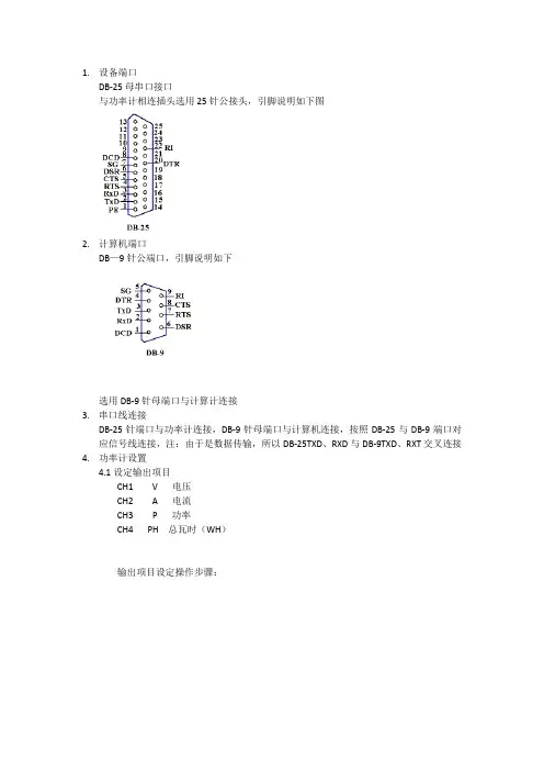
1.设备端口
DB-25母串口接口
与功率计相连插头选用25针公接头,引脚说明如下图
2.计算机端口
DB—9针公端口,引脚说明如下
选用DB-9针母端口与计算计连接
3.串口线连接
DB-25针端口与功率计连接,DB-9针母端口与计算机连接,按照DB-25与DB-9端口对应信号线连接,注:由于是数据传输,所以DB-25TXD、RXD与DB-9TXD、RXT交叉连接4.功率计设置
4.1设定输出项目
CH1 V 电压
CH2 A 电流
CH3 P 功率
CH4 PH 总瓦时(WH)
输出项目设定操作步骤:
4.2串口参数设置
程序使用参数:
只讲模式LONELY
握手协议HAND0(表示无握手协议)
数据格式FOR_0
波特率B_9600
结束符LF(\n)
设定时间间隔00.00.00(按显示更新周期输出数据)或00.00.01(每秒输出1次数据)
5.计算机程序参数设置
6.在VISA READ----字节总数端加入属性节点可以避免出现关于串口
缓存的错误
注:本程序只实现测试数据的读取功能,更高级的功能不包含在本程序中
程序框图
字符串转换为数字子程序
主程序。
谐波如何测试?1.谐波测试两种主要方式有源RF和FEM的第二个关键属性是谐波行为。
谐波行为由非线性器件引起,会导致在比发射频率高数倍的频率下产生输出功率。
由于许多无线标准对带外辐射进行了严格的规定,所以工程师会通过测量谐波来评估RF或FEM是否违反了这些辐射要求。
测量谐波功率的具体方法通常取决于RF的预期用途。
对于通用RF等器件备来说,谐波测量需要使用连续波信号来激励DUT,并测量所生成的不同频率的谐波的功率。
相反,在测试无线手机或基站RF时,谐波测量一般需要调制激励信号。
另外,测量谐波功率通常需要特别注意信号的带宽特性。
1)使用连续波激励测量谐波使用连续波激励测量谐波需要使用信号发生器和信号分析仪。
对于激励信号,需要使用信号发生器生成具有所需输出功率和频率的连续波。
信号发生器生成激励信号后,信号分析仪在数倍于输入频率的频率下测量输出功率。
常见的谐波测量有三次谐波和五次谐波,分别在3倍和5倍的激励频率下进行测量。
RF信号分析仪提供了多种测量方法来测量谐波的输出功率。
一个直截了当的方法是将分析仪调至谐波的预期频率,并进行峰值搜索以找到谐波。
例如,如果要测量生成1GHz信号时的PA三次谐波,则三次谐波的频率就是3GHz。
测量谐波功率的另一种方法是使用信号分析仪的零展频(zero span)模式在时域中进行测量。
配置为零展频模式的信号分析仪可以有效地进行一系列功率带内测量,并将结果以时间的函数形式表现出来。
在此模式下,可以在时域上测量选通窗口中不同频率的功率,并使用信号分析仪内置的取平均功能进行计算。
2)使用调制激励的谐波实际上,许多PA被用来放大调制信号,而且这些PA的谐波性能需要调制激励。
与使用连续波类似,通常在接近设备饱和点的功率电平下,将已知功率激励信号发送到PA的输入端。
测量谐波输出功率时,工程师通常会根据测量时间和所需的准确度等不同限制条件而采用图通方法。
实际上,3GPP LTE和IEEE 802.11ac等无线标准并没有对谐波的要求进行具体的规定,而是规定了在一定频率范围内最大杂散辐射要求。
谐波电流测试方法谐波电流的存在会对电力系统产生一定的影响,因此准确地测试和分析谐波电流显得尤为重要。
在本文中,我们将介绍一种常用的谐波电流测试方法,以帮助读者更好地理解和应用于实际工程中。
一、谐波电流测试的背景在电力系统中,电流通常由正弦波组成,但谐波电流则包含了频率是基波频率整数倍的成分。
这些谐波电流可能会导致电力系统中出现电压失真、功率损耗以及设备故障等问题。
因此,对谐波电流进行准确可靠的测试是非常重要的。
二、谐波电流测试的原理谐波电流测试的原理是利用谐波分析仪对电流进行检测和分析。
该仪器能够分解电流波形,并直观地显示谐波电流及其幅值、相位等相关参数。
谐波分析仪通常采用采样技术和数字信号处理等先进技术,以确保测试的准确性和精度。
三、谐波电流测试的步骤1. 准备工作:首先,确保测试设备和测试仪器工作正常。
检查电流传感器的连接和校准,确保其准确地测量电流信号。
2. 测试回路:选择需要测试的电流回路,并将测试仪器的传感器连接到回路上。
根据实际情况,选择合适的传感器类型和连接方式。
3. 设置测试参数:根据具体需求,设置测试仪器的参数。
包括采样频率、谐波阶数等。
根据测试仪器的使用说明书,正确设置参数能够提高测试的准确性。
4. 进行测试:启动测试仪器,开始进行电流测试。
测试仪器会自动采集和分析电流信号,并将测试结果以图形或数据的形式显示出来。
5. 分析和结果:根据测试结果,进行谐波电流的分析和判断。
根据具体情况,评估谐波电流对电力系统的影响,并采取相应的措施进行处理。
四、谐波电流测试的注意事项1. 保护设备:在进行电流测试时,特别是在高电压环境下,务必采取必要的安全措施,保护测试仪器和测试人员的安全。
2. 数据可靠性:测试过程中,应确保测试数据的可靠性和准确性。
避免测试误差和干扰,保持测试环境的稳定和静默。
3. 结果分析:对测试结果进行全面和综合的分析,不仅仅局限于谐波电流的幅值和相位等参数,还需考虑电流的谐波分布、波形失真等因素。
供电系统谐波的定义是对周期性非正弦电量进行傅立叶级数分解,除了得到与电网基波频率相同的分量,还得到一系列大于电网基波频率的分量,这部分电量称为谐波。
谐波频率与基波频率的比值(n=fn/f1) 称为谐波次数。
电网中有时也存在非整数倍谐波,称为非谐波(Non-harmonics )或分数谐波。
谐波实际上是一种 干扰量,使电网受到“污染”。
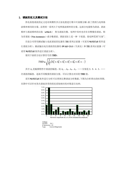
目前公司常用测试输入电流谐波的仪器有TEK 系列示波器(可采用WAVESTAR 软件进行谐波分析),测试输出电压谐波的仪器有GW GAD-201G (失真仪)和TEK 系列示波器(可采用WAVESTAR 软件进行谐波分析)。
使用下面的方法计算信号的THD : () ++++++=272625242322211A A A A A A A THD 其中A 1是幅频特性中基波的幅值,而A 2 、A 3、A 4、A 5、……分别是2、3、4、5、……次谐波的幅值。
选取不同数量的谐波分量,可以计算出对应的THD 值。
采用WAVESTAR 软件进行分析可以得到完整谐波分析数据,下图为分析得出的柱型图,从图中可以针对各次谐波异常的状况采取相应的对策进行改善: Harmonic magnitude as a % of the fundamental amplitude0.0%0.7%1.5%2.2%3.0%3.7%4.4%5.2%5.9%6.6%7.4%8.1%Voltage:Current: Ch 1# Harmonics: 20Type: Current Magnitude波峰因数定义为交流信号峰值与有效值之比(峰均比),典型的波峰因数是: 正弦波:1.414;方波: 1;25%的占空比的脉冲:2 。
波峰因数(CREST FACTOR )的概念在UPS 行业是用来衡量UPS 带非线性负载的能力,对线性负载(R LOAD )而言,正弦波电流峰值Ipeak 与均方根值Irms 之比为1.414:1;在非线性负载(RCD LOAD )时,波峰因数则被认定为:在相同的有功功率条件下,非线性负载的电流峰值与非线性负载电流均方根值之比。
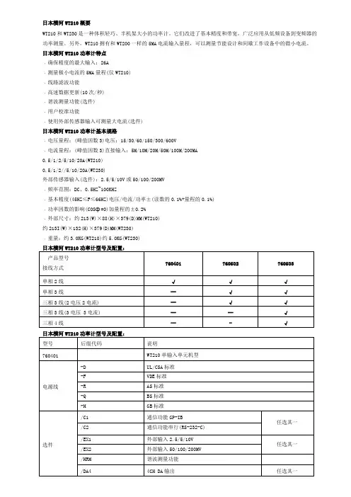
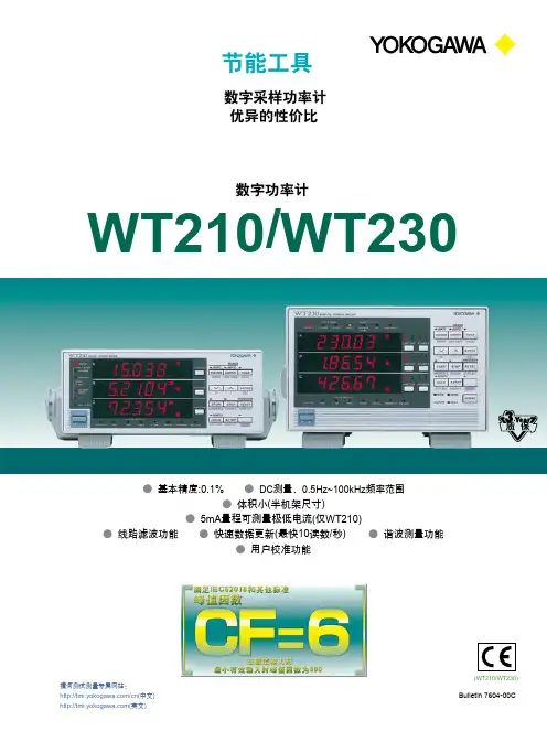
日本横河WT210概要
WT210和WT230是一种体积轻巧、半机架大小的功率计。
它们改进了基本精度和带宽,广泛应用从低频设备到变频器的功率测量。
另外,WT210拥有和WT200一样的5MA电流输入量程,可以测量节能设计和间歇工作设备中的微小电流。
日本横河WT210功率计特点
﹒确保精度的最大输入:26A
﹒测量极小电流的5MA量程(仅WT210)
﹒线路滤波功能
﹒高速数据更新(10次/秒)
﹒谐波测量功能(选件)
﹒用户校准功能
﹒使用外部传感器输入可测量大电流(选件)
日本横河WT210功率计基本规格
﹒电压量程:(峰值因数3)电压:15/30/60/150/300/600V
﹒电流量程:(峰值因数3)直接输入:5M/10M/20M/50M/100M/200MA
0.5/1/2/5/10/20A(WT210)
0.5/1/2//5/10/20A(WT230)
外部传感器输入(选件):2.5/5/10V或50/100/200MV
﹒频率范围:DC、0.5HZ~100KHZ
﹒基本精度(45HZ≤F≤66HZ)电压/电流/功率±(读数的0.1%+量程的0.1%)
﹒功率因数的影响(COSф=0)加量程的±0.2%
﹒外部尺寸:约213(W)×88(H)×379(D)MM(WT210)
约213I(W)×132(H)×379(D)MM(WT230)
﹒重量:约3.0KG(WT210)约5.0KG(WT230)。

浅述谐波功率测量摘要:非线性负载引起交流正弦波畸变产生谐波,污染工频电网。
电力系统中存在的大量谐波对电能计量的准确性产生了严重的影响。
谐波测量是谐波问题研究的出发点和主要依据,概述了电力系统谐波度量方法,并对电力系统谐波测量的方法进行了分析和评述。
通过对电能计量中谐波影响因素的分析,不断提高电能计量的准确性。
关键词:谐波测量;谐波功率;电能表;小波分析电能计量是发电企业、输配电企业、电力用户之间进行贸易结算的依据,它的准确性与合理性直接影响三者之间的利益。
而另一方面.随着电力电子技术的发展,大量的电力电子变流装置和各种非线性负载的比重不断增加,引起电力系统中的电流和电压波形产生畸变。
从频域的角度来看,在这些畸变的电流和电压波形中,不仅仅包含与供电电源同频率的正弦量,而且出现了一系列的频率为基波整数倍的正弦分量。
这一系列的正弦分量统称为谐波。
电力系统谐波不仅对供电系统造成污染,对电力设备构成危害,而且产生谐波的非线性用户将其吸收的一部分基波电能转化为谐波电能,并反馈给电网,造成供电企业线损增加,电力营运企业非经营性成本增加。
为此有必要研究在谐波影响下的电能计量,使电能计量管理更加合理[1,2]。
1 谐波功率的产生及危害随着电力电子技术的发展,非线性负载是普遍存在的[3,4],尤其是晶闸管(可控硅)技术的发展,工农业、交通部门都在大量使用硅整流、换流和变频技术,例如电气化铁路采用单相交流电硅整流,冶金部门在轧钢机、电弧炼钢炉,矿山的卷扬机,有色金属冶炼的电解槽,化工部门的电离加工等等方面都离不开硅整流设备。
就是在家用电器方面也少不了采用硅整流技术。
如电视机、计算机、洗衣机、变频空调、手机、电动车电池的各种充电器和开关电源以及冷光照明、节能灯和调光灯等等都属于非线性负载。
在电力生产运行中,由于用户的这些非线性负载对电网产生了严重的有害影响。
主要原因是这些负载产生大量的高次谐波电流,而单相非线性负载还产生不对称的高次谐波和不平衡负载,造成屯网电压波形严重畸变和三相不平衡。
谐波检测方法谐波是指在正弦波的基础上,频率是基波频率的整数倍的波。
在电力系统中,谐波是一种常见的电力质量问题,它会导致电网设备的过热、振动、噪音增加,甚至影响电能表的准确度。
因此,对谐波进行有效的检测和分析至关重要。
一、传统的谐波检测方法。
传统的谐波检测方法主要包括使用示波器、功率分析仪和谐波分析仪等设备进行采样和分析。
这些方法需要在现场进行操作,需要专业技术人员进行操作和分析,成本较高且操作不够便捷。
而且,这些方法只能对特定点进行采样,无法对整个电网系统进行全面的谐波监测。
二、现代的谐波检测方法。
随着科技的发展,现代的谐波检测方法逐渐成熟并得到广泛应用。
其中,基于数字信号处理技术的谐波检测方法成为了主流。
通过在电网系统中部署智能传感器和数据采集设备,可以实现对整个电网系统的实时谐波监测。
这些智能设备可以将采集到的数据通过网络传输到监测中心,实现远程实时监测和分析。
三、基于人工智能的谐波检测方法。
近年来,随着人工智能技术的快速发展,基于人工智能的谐波检测方法也逐渐崭露头角。
利用深度学习和神经网络等技术,可以对大量的谐波数据进行自动化的分析和识别。
这种方法可以大大提高谐波检测的效率和准确性,减少人为因素对检测结果的影响。
四、结语。
随着电力系统的不断发展和智能化水平的提高,谐波检测方法也在不断演进和完善。
传统的检测方法逐渐被现代化的技术所取代,基于数字信号处理和人工智能的谐波检测方法成为了未来的发展方向。
我们相信,随着技术的不断进步,谐波检测方法将会变得更加智能、准确和高效。
这将有助于提高电力系统的稳定性和可靠性,为人们的生活和生产带来更多的便利和安全。
以上就是关于谐波检测方法的相关内容,希望对您有所帮助。
1.11
月3日测试数据:
PA310与WT210积分测量计算出的效率值基本一致,PA310功率读数与积分测量计算
的功率数据也一致,WT210的电流、功率读数不稳定,在开关电源空载或者负载较小时,读数跳动幅度达到5%以上。
2.Chroma 6530给开关电源供电时,输出电流存在200kHz的干扰,幅值20-30mA,波形如下图所示:
3. 根据奈奎斯特采用定律,当采用频率不足被测信号2倍的时候,会发生混淆现象,如下图所示,被测信号频率与功率计采样率越接近,测量误差越大。
4.由于之前PA310的采样率为200kS/s,与Chroma 6530的干扰信号频率十分接近,而且在待机情况下,干扰信号电流幅值接近甚至大于基波幅值,会产生比较严重频率混叠现象,导致读数跳动。
得益于全新的FPGA+DSP架构,PA310具有更强大的数据处理能力,采样率目前已升级为500kS/S,超过输入带宽200kHz的2倍,已经从根源上杜绝了频率混叠现象。
5.WT210受限于10年前的硬件方案,数据运算能力无法支撑更高的采样率。
为防止频率混叠现象,WT210采用了动态切换采样率的方式:
采样率在几种不同频率间切换,保证最多只有一个采样率会出现严重偏差(和干扰信号最接近的采样率),其余采样率下测试正常。
但这种算法会带来另外一个问题:当测试信号谐波含量较高时,不同的采样率测得的数据相差较大,就如我们看到的WT210电流、功率读数跳动现象。
电力系统谐波测量方法综述引言:20世纪70年代以来,随着电子技术的飞速发展,各种电力电子装置在电力系统、工业、交通及家庭中的应用日益广泛,谐波污染状况及危害程度呈急剧上升趋势。
由于电力电子装置所产生的谐波污染问题是阻碍电力电子技术发展的重大障碍,无法回避,且谐波污染对电力系统存在严重的危害,准确地掌握电网中的谐波成分对于电力系统的安全、经济运行具有重要的意义。
谐波测量是谐波问题中的一个重要分支,也是研究分析谐波问题的出发点和主要依据。
谐波测量的主要作用有:(1)鉴定实际电力系统及谐波源用户的谐波水平是否符合标准的规定,包括对所有谐波源用户的设备投运时的测量。
(2)电气设备调试、投运时的谐波测量,以确保设备投运后电力系统和设备的安全及经济运行。
(3)谐波故障或异常原因的测量。
(4)谐波专题测试,如谐波阻抗、谐波潮流、谐波谐振和放大等。
现有的谐波分析方法主要有快速傅立叶变换,p、q分解法以及基于瞬时无功功率理论的虚实功率合成法,小波、人工神经网络以及支持向量机等方法,本文分析了个方法的优缺点并在其基础上作了验证。
1、采用模拟带通或带阻滤波器测量谐波图1采用模拟滤波器谐波测量结构图输入信号经放大后送入一组并行联结的带通滤波器,滤波器的中心频率f1、f2、⋯、fn 是固定的,为工频的整数倍,且f1< f2<⋯<fn (其中n 是谐波的最高次数),然后送至多路显示器显示被测量量中所含谐波成分及其幅值。
采用模拟滤波器谐波测量优点是电路结构简单,造价低。
但该方法也有许多缺点,如滤波器的中心频率对元件参数十分敏感,受外界环境影响较大,难以获得理想的幅频和相频特性,当电网频率发生波动时,不仅影响检测精度,而且检测出的谐波电流中含有较多的基波分量。
2、基于傅立叶变换的谐波测量基于傅立叶变换的谐波测量是当今应用最多也是最广泛的一种方法。
它由离散傅立叶变换过渡到快速傅立叶变换的基本原理构成。
使用此方法测量谐波,精度较高,功能较多,使用方便。
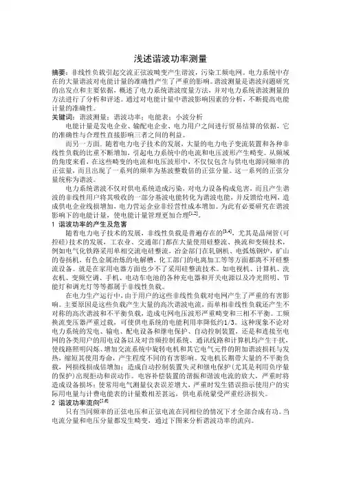
日本横河WT210数字功率计日本横河WT210数字功率计是一种测试电路板或设备输出、输入功率的仪器。
它由日本横河电气公司发明,已成为业界知名的功率计产品。
本文将对该产品进行详细介绍。
仪器特点日本横河WT210数字功率计具有以下几个特点:高精度从精确度来看,日本横河WT210数字功率计达到了0.1%级别。
这意味着在大多数应用场合下,WT210可以准确的测试电路板或设备的输入、输出功率,对于各类工业生产和研发实验室等场合都特别适用。
宽频带WT210数字功率计拥有宽频带功能,能够支持传统60Hz市电的测试,同时还可以支持高速开关电源等各种带有中高频噪声的功率测量。
可扩展性除了基本套装外,WT210还提供了多种软件插件,比如电机测试插件、太阳能测试插件等多种插件,便于用户根据不同需求进行扩展。
易用性WT210数字功率计采用人性化设计,可以支持多种语言,并且使用简便。
仪器自带许多测试模式、测试报告和异常警报等功能,可以大大减轻用户的负担。
技术参数下面对日本横河WT210数字功率计的主要技术参数进行介绍:•电压范围:30mV 至 1000V(自动)•电流范围:30mA 至 20A(自动)•精度:0.1% 全范围(整流器和非整流器)•功率测试范围:8kW(与线圈长度无关)•频率范围:45至66Hz 或 320至 1000Hz•不确定度:±0.15%(45Hz至5kHz),±0.4%(5kHz至100kHz)应用场景WT210数字功率计可广泛应用于各种场合。
比如在电机制造业、变频器制造业、航空航天和军事制造业、研究与开发等领域都有着广泛的应用。
经济性和价值虽然日本横河WT210数字功率计的价格相对较高,但相比其他同类产品,它的性能稳定性、精度和可靠性都表现得非常突出。
它也提供了丰富的扩展插件,便于用户根据自身需求进行扩展。
因此,WT210数字功率计的成本产生不高,通常可以帮助用户在工业生产和研究开发中提高生产效率和产品性能,具有很高的经济价值和使用价值。
ENERGY SAVING TOOLS Digital Sampling Power Meters with Superior Cost PerformanceWT230WT210130% input1% inputFunctions and Features of the WT210 and WT230●A Wide Frequency Range Lets You Work on a Variety of Different Applications2: Conditions apply to accuracy from 110% to 130%.●Powerful Tools for Energy Measurement●Wide range of 5 mA to 20 AThe built-in 5 mA range lets you measure currents as low as 25 µA. This makes it possible to measure very low currents on such things as intermittent control equipment. The wide current range (5 mA to 20 A) means a single power meter can be used for applications such as Energy Star® measuremnts, to measure everything from standby-power to rated-power.GP-IB/serial interface (RS-232-C)ExternalD/A outputComparator outputRecorderClamp probe The WT230’s advanced specifications and its wide range of functions let you handle all your measurement applications from low-frequency equipment to high frequency inverters using a single power meter.One unit also handles standby low-power measurements and rated-power measurements (functions available with the WT210 only).960 01751552N E W wareSoft Fr ee WTViewer for the WT210/WT230Easily Acquire and Manage Power Measurement Data from Your PCSee 8 pages orBulletin 7604- 32E for details.5ParameterVoltage15/30/60/150/300/600 VInput resistance: Approximately 2 M ΩInput capacitance: Approximately 13 pF Peak voltage of 2.8 kV or rms value of 2.0 kV (whichever is less)Peak voltage of 2.0 kV or rms value of 1.5 kV (whichever is less)Peak voltage of 1.5 kV or rms value of 1.0 kV (whichever is less)600 Vrms (with output connector protective cover), CA T II / 400 Vrms (without output connector protective cover) CA T II50/60 Hz, -80 dB or higher (±0.01% of range or less) with voltage input terminals shorted and current input terminals open and external input terminals shorted Reference value (up to 100 kHz): ±((Maximum range rating)/(Range rating) × 0.001 × f% of rng) or less (voltage range and 0.5-20 A current range and external input range 3)±((Maximum range rating)/(Range rating) × 0.0002 × f% of rng) or less (WT210; 5-200 mA range)Note: 0.01% or higher. f is in kHz. 3 Decuple the above-formula about the external input range.Resistance voltage dividerCurrentShunt input system Direct input:5/10/20/50/100/200 mA (WT210 only)1; 0.5/1/2/5/10/20 A (WT210/WT230)External input (optional): 2.5/5/10 V or 50/100/200 mVDirect input:Approximately 500 m Ω + approximately 0.1 µH (5-200 mA; WT210)Approximately 6 m Ω + 10 m Ω (max)2 + approximately 0.1 µH (0.5-20 A; WT210)Approximately 6 m Ω approximately 0.1 µH (0.5-20 A; WT230)External input: Approximately 100 k Ω (2.5/5/10 V), approximately 20 k Ω (50/100/200 mV)0.5-20 A (WT210/WT230): Peak current of 450 A or rms value of 300 A (whichever is less)5-200 mA (WT210): Peak current of 150 A or rms value of 100 A (whichever is less)External input: Peak value of 10 times range or less0.5-20 A (WT210/WT230): Peak current of 150 A or rms value of 40 A (whichever is less)5-200 mA (WT210): Peak current of 30 A or rms value of 20 A (whichever is less)External input: Peak value of 10 times range or less0.5-20 A (WT210/WT230): Peak current of 100 A or rms value of 30 A (whichever is less)5-200 mA (WT210): Peak current of 30 A or rms value of 20 A (whichever is less)External input: Peak value of 5 times range or lessInput typeRated values (ranges)Measuring instrument loss (input resistance)Maximum instantaneous allowed input (1 cycle, 20 ms duration)Maximum instantaneous allowed input (1 second duration)Maximum continuous allowed inputMaximum continuous common mode voltage (with 50/60 Hz input)CMRR600 Vrms across input terminal and caseFloating inputInput SpecificationsPlug-in terminal (safety terminal)Direct input: Large binding postExternal input: BNC connector (insulation type)Input terminal type A/D converterSimultaneous conversion of voltage and current inputs Resolution: 16 bitsMaximum conversion speed: Approximately 20 µs (approximately 51 kHz)Range switchingRanges can be set manually, automatically, or through online controls. Auto-range functionRange raising: When a measurement exceeds 130% of the rating, or when the peak value exceeds approximately 300% of the ratingRange lowering: When a measurement falls to 30% or less of the rating, and the peak value falls to approximately 300% or less of the rating for the low range Measurement mode switchingAny of the following, selected manually or through online controls: RMS (true rms value measurements for both voltage and current), V MEAN (calibration of average-value-rectified rms value for voltage; true rms value measurement for current), DC (simple averages for both voltage and current)Note: Current direct input and external sensor input cannot both be used at the same time. When you operate current input terminals and external input terminals, please be careful.Since these terminals are electrically connected inside the instrument.1, Connect wires that match the size of the measurement current.2, Factory settingParameterVoltage/currentDC:0.5 Hz ≤ f < 45 Hz:45 Hz ≤ f ≤ 66 Hz:66 Hz < f ≤ 1 kHz:1 kHz < f ≤ 10 kHz:10 kHz < f ≤ 100 kHz:* Add ±10 µA to the current DC accuracy.1-130% of voltage/current range rating (for accuracy at 110-130%, add the reading tolerance × 0.5 to the above accuracy) Add the accuracy's reading tolerance (three months after calibration) × 0.5 to the accuracy three months after calibration.A low-pass filter can be inserted in the input circuit for measurement. The cutoff frequency (fc) is 500 Hz.Voltage and current: Add 0.2% of rdg at 45-66 Hz. Add 0.5% of rdg below 45 Hz.Power: Add 0.3% of rdg at 45-66 Hz. Add 1% of rdg below 45 Hz.±0.03% of range/°C at 5-18°C and 28-40°C.0.1/0.25/0.5/1/2/5 secondsData updating rate0.1 second 0.25 second 0.5 second 1 second 2 seconds 5 seconds Measurement lower limit frequency25 Hz10 Hz5 Hz2.5 Hz1.5 Hz0.5 Hz±(0.2% or rdg + 0.2% of rng)*±(0.1% of rdg + 0.2% of rng)±(0.1% of rdg + 0.1% of rng)±(0.1% of rdg + 0.2% of rng)±((0.07 × f)% of rdg + 0.3% of rng)±((0.5% of rdg + 0.5% of rng) ±((0.04 × (f-10))% of rdg)Active powerDC:0.5 Hz ≤ f < 45 Hz:45 Hz ≤ f ≤ 66 Hz:66 Hz < f ≤ 1 kHz:1 kHz < f ≤ 10 kHz:10 kHz < f ≤ 100 kHz:* Add ±10 µA × voltage reading to the power DC accuracy.For cos ϕ = 045 Hz ≤ f ≤ 66 Hz: ±0.2% of VA (VA is a reading value of apparent power)Reference data (up to 100 kHz): ±((0.2 + 0.2 × f)% of VA)Indicated value tolerance for 0 < cos ϕ < 1Add (tan ϕ × (effect when cos ϕ = 0)% of power reading to the above power accuracy.Note: ϕ is the phase angle between voltage and current.±(0.3% or rdg + 0.2% of rng)*±(0.3% of rdg + 0.2% of rng)±(0.1% of rdg + 0.1% of rng)±(0.2% of rdg + 0.2% of rng)±(0.1% of rdg + 0.3% of rng) ±((0.067 × (f-1))% of rdg)±(0.5% of rdg + 0.5% of rng) ±((0.09 × (f-10))% of rdg)SystemFrequency range Crest factorAccuracy (three months after calibration) (Conditions)T emperature: 23±5°C Humidity: 30-75% RHInput waveform: Sinewave Power factor: cos ϕ = 1 In-phase voltage: 0 V DCFrequency filter: ON at 200 Hz or less Scaling: OFFDisplay digits: 5 digits After CAL is executedNote: In the accuracy calculation formula, f is in kHz.Power factor effectNote: In the accuracy calculation formula, f is in kHz. Effective input rangeAccuracy (12 months after calibration)Line filter functionAccuracy with line filter on T emperature coefficient Display updating intervals Measurement lower limit frequencyDigital sampling; sum of averages methodDC, and 0.5 Hz to 100 kHz3 (with rated input) 300 (with minimum effective input)Measurement Functionsrng: Range rdg: ReadingLead/lag is detected correctly when phase difference equal to or greater than ±5° with both voltage and current inputs as sine waves equal to or greater than 50% of rated range-value, and the frequency is between 20 Hz to 2 kHz.Lead/lag detectingThe latest product information is available at our web site /tm/. Review the specifications to determine which model is right for you.Frequency MeasurementsMeasurement inputs :V1, V2, V3, A1, A2, or A3 (select one)Measurement system :Reciprocal system Measurement frequency ranges100 ms:25Hz ≤ f ≤100 kHz 250 ms:10Hz ≤ f ≤100 kHz 500 ms: 5Hz ≤ f ≤100 kHz 1 sec: 2.5Hz ≤ f ≤100 kHz 2.5 sec:1.5Hz ≤ f ≤50 kHz 5 sec:0.5Hz ≤ f ≤20 kHzAccuracy:±(0.06% of rdg)Conditions:Input equal to at least 30% of voltage/current rated range.Frequency filter function ON at 200 Hz and below.Frequency filter cutoff frequency: 500 HzCommunication Functions (Optional for the WT210)GP-IB or serial interface (RS-232-C) (select one)GP-IBElectrical and mechanical specifications:Conform to IEEE Standard 488-1978 (JIS C1901-1987).Functional specifications:SH1, AH1, T5, L4, SR1, RL1, PR0, DC1, DT1, C0Protocol:Conforms to IEEE Standard 488.2-1992.Code used:ISO (ASCII) code Addresses:0-30 talker/listener addresses can be set.Serial interface (RS-232-C)Transmission mode :Asynchronous Baud rates:1200, 2400, 4800, 9600 bps62333Single-phase 3-wire Three-phase 3-wire (2 voltages, 2 currents)Three-phase 3-wire (3 voltages, 3 currents)Three-phase 4-wireVoltage ∑V (V1 + V3)/2(A1 + A3)/2W1 + W3(V1 + V2 + V3)/3(A1 + A2 + A3)/3W1 + W2 + W3var1 + var2 + var3VA1 + VA2 + VA3Current ∑A Active power ∑WPower factor PF , ∑PF Phaseangle deg, ∑degdegi =cos -1 (Wi/VAi)Reactive power var, ∑var Apparent power VA, ∑VA vari = (VA 2 - W 2)VAi = Vi × Ai Pfi = Wi/VAi ∑W/∑VA cos -1 (∑W/∑VA)VA1 + VA3var1 + var3(VA1 + VA3)(VA1 + VA2 + VA3)Notes1.This equipment's apparent power (VA), reactive power (var), power factor (PF),and phase angle (deg) are calculated from voltage, current, and active power.(Therefore, if the input contains a distorted wave, the values may not match those of other measuring instruments based on different measurement principles.)2.If either voltage or current falls to 0.5% of the range rating or less, then the apparent power (VA) and reactive power (var) are displayed as zero, and errors are displayed for power factor (PF) and phase angle (deg).3.The sign of the var of each phase is displayed with +(positive). In the ∑var calculation, the var value for each phase is calculated with a negative sign if the current input leads the voltage input, and with a positive sign if the current input lags the voltage input. Then the value of ∑ var may be displayed with –(negative).4.Apparent power (VA) and reactive power (var) cannot be calculated and displayed at the harmonics measurement mode.Display FunctionsDisplay unit:7-segment LED (light-emitting diode)Display areas:3V , A, W, VA, var (for each element), integration elapsed timeV , A, W, PF , deg (for each element, percentage (content percentage, THD)V , A, W, V/AHz, Vpk, Apk, ±Wh, ±Ah (for each element), MA THDisplay areaA B CDisplayed informationMeasurement parameters Maximum display Display resolutionV , A, W, VA, var PF deg ±Wh, ±AhVHz, AHz 99999±1.0000±180.0999999999990.001%0.01%0.1*0.0001%Input frequency/20,000Display digits: 4 or 5 digits (selectable by user).Factory default setting is 5 digits.Units:m, k, M, V , A, W, VA, var, Hz, h ±, deg, %Display updating intervals: 0.1/0.25/0.5/1/2/5 seconds Response time:Maximum 2 times the display updating interval (time requiredfor display value to enter accuracy range of final value with line filter off, when range rating abruptly changes from 0% to 100%,and from 100% to 0%)Maximum display:140% of voltage/current range rating Minimum display:About Vrms, Arms, and Ah, 0.5% of range rating.Less than 0.5% is zero suppression.Display scaling functionEffective digits:Selected automatically according to the digits in the voltage andcurrent ranges.Setting range:0.001 to 9999Averaging functionThere are two averaging methods (selectable by user):Exponential average Moving averageIn cases where response can be set and exponential average is used, the attenuation constant can be selected. In cases where a moving average is used, the number of averages N can be selected from 8, 16, 32, and 64.Auto-range monitorAn LED turns on when the input value is outside the range set for the auto-range.MAX hold functionThis function can be used to hold V, A, W, VA, var, Vpk, and Apk at maximum values.MA TH functions System:When a function key on DISPLA Y C is pressed to select theMATH functions, it is possible to perform efficiency (WT230 only)and input crest factor measurements, as well as arithmetic calculations on DISPLAY A and B measurements. In addition, it is possible to display average active power for time-converted integrated power.Integration FunctionsDisplay resolution:The minimum display resolution changes together with the integrated value.Maximum display:-99999 to 999999 MWh/MAhModes:Standard integration mode (timer mode), continuous integration mode (repeat mode), manual integration modeTimer:Automatic integration start/stop based on timer setting.Setting range: 000 h:00 min:00 sec to 10000 h:00 min:00 sec (If the time is set to zero, manual mode is automatically set.)Count over flow:When the integrated value exceeds 999999 MWh/MAh or falls to at least -99999 MWh/MAh, the elapsed time is saved and the operation is stopped.Accuracy:±(display accuracy + 0.1% of rdg)Timer accuracy:±0.02%Remote control:Starting, stopping, and resetting can be controlled through external contact signals. This function is only available when option /DA4, /DA12 or /CMP is installed.Calculation FunctionsInternal Memory FunctionsMeasurement dataStored data WT210 (760401)WT230 (760502)WT230 (760503)Normal measurement Data for 600 samples Data for 300 samples Data for 200 samplesHarmonic measurement Data for 30 samples Data for 30 samples Data for 30 samplesStore interval:Display updating interval and 1 second to 99 hours, 59 minutes,and 59 secondsRecall interval:Display updating interval and 1 second to 99 hours, 59 minutes,and 59 seconds(Both can be set in 1-second increments.)Panel setting information :Four different patterns of panel setting information can be written/read.Harmonic Measurement Function (optional)System:PLL synchronization Measurement frequency range:Fundamental frequency in range of 40-440 HzMaximum display:99999Display digits: 4 or 5 digits (selectable by user).Factory default setting is 5 digits.Measurement parameters: V , A, W, deg (WT210), V1, V2, V3, A1, A2, A3, W1, W2,W3, deg1, deg2, deg3 (WT230), individual harmonic levels, rms voltage, rms current, active power, fundamental frequency PF ,harmonic distortion rate, individual harmonic contentMeasurement element: These parameters can only be measured simultaneously fora single specified input element.Sampling speed, window width, and analysis ordersThe values for these parameters vary according to the input fundamental frequency as shown below.Fundamental frequency Sampling speed Window width Analysis orders 40 ≤ f < 70 Hz f × 512 Hz 2 periods of f 50 70 ≤ f < 130 Hz f × 256 Hz 4 periods of f 50130 ≤ f < 250 Hz f × 128 Hz 8 periods of f 50250 ≤ f ≤ 440 Hz f × 64 Hz 16 periods of f 30FFT data length:1024FFT processed word length: 32 bits Window function:Rectangular Display updating interval:0.25/0.5/1/2/5 seconds Updating is slower during online output according to the communication speed and the number of parameters transferred.Accuracy:Add ±0.2% of range to normal measurement accuracy.Note:For nth-order component input, add ((nth order reading)× (10/(m+1))%) to the n+mth order and n-mth order.D/A Output (optional)Output voltage:±5 V FS (maximum approximately ±7.5 V) for each rated value Number of outputs:12 parameters with /DA12 option; 4 parameters with /DA4 option Output data selection :Can be set separately for each channel.Accuracy:±(equipment accuracy + 0.2% of FS)D/A converter:12-bit resolution Response time:Maximum 2 times the display updating interval Updating interval:Same as the equipment's display updating interval Temperature coefficient:±0.05%˚C of FS Output typeD/A output7.5V 5.0V2.5V0.5V00.5Hz 100Hz10Hz1Hz1kHz10kHz Display value100kHz FrequencyIntegrationD/A output7.0V5.0Vt0Integration timeFor input equal to 140% of ratingFor rated inputt0: Rated setting timeOther parameters0V-100%-140%-5.0V -7.0V -7.5V5.0V7.0V 7.5V 140%100%D/A outputDisplay valueDisplay 140% 100% 0%-100%-140%Output 7.0V 5.0V 0V -5.0V -7.0VNote: For PF and deg, there is no output between ±5 and ±7 V. When an error occurs,approximately 7.5 V are output.7External Input (Optional)Select either /EX1 or /EX2 for the voltage output-type current sensor./EX1: 2.5/5/10 V /EX2:50/100/200 mV Specifications:See the section on input specifications.Comparator Output (Optional)Output method:Normal-open and normal-close relay contact output (pair)Number of output parameters and settings:Four parameters; can be set separately on each output channel.Contact capacitance:24 V/0.5 AD/A output (4-channel):See section on D/A output (optional)External Control Signal (with D/A or /CMP Option Only)External control signals :EXT -HOLD, EXT -TRIG, EXT -START, EXT -STOP , EXT -RESET ,INTEG-BUSYInput:TTL level negative pulseGeneral SpecificationsWarmup time:Approximately 30 minutesOperating temperature and humidity ranges: 5-40˚C, 20-80% RH (no condensation)Storage temperature :-25-60˚C (no condensation)Maximum operating elevation: 2000 metersInsulating resistance :50 M Ω or higher at 500 V DC across all of the following areas:Voltage input terminals (ganged) and case Current input terminals (ganged) and caseVoltage input terminals (ganged) and current input terminals (ganged)Voltage input terminals (ganged) of each element Current input terminals (ganged) of each element Voltage input terminals (ganged) and power plug Current input terminals (ganged) and power plug Case and power plugInsulating withstand voltage:3700 V for one minute at 50/60 Hz across all of the following areas:Voltage input terminals (ganged) and case Current input terminals (ganged) and caseVoltage input terminals (ganged) and current input terminals (ganged)Voltage input terminals (ganged) of each element Current input terminals (ganged) of each element Voltage input terminals (ganged) and power plug Current input terminals (ganged) and power plug1500 V for one minute at 50/60 Hz across case and power plug Power supply:Free power supply (100-240 V), 50/60 Hz frequency Consumed power:Max 35 VA for WT210, max 55 VA for WT230External dimensions for WT210:Approximately 213 × 88 × 379 mm (WHD) (excluding projections)External dimensions for WT230:Approximately 213 × 132 × 379 mm (WHD) (excluding projections)Weight:Approximately 3 kg for WT210, approximately 5 kg for WT230Safety standard Complying standard EN61010-1Overvoltage category (Installation category) II Pollution degree 2Emission Complying standard EN61326 Class AEN61000-3-2EN61000-3-3AS/NZS 2064 Class AImmunity Complying standard EN61326 Annex A■Exterior ViewUnit : mmWT210WT23021332728.51322113233425073233562131798819359760401Power cord Options-D-F -R -Q/C1/C2/EX1/EX2/HRM /DA4/CMPWT210 single-input element modelUL/CSA standard VDE standard AS standard BS standardGP-IB communication interfaceSerial (RS-232-C) communication interface External input 2.5/5/10 V External input 50/100/200 mV Harmonic measurement function 4-channel DA outputComparator and D/A, 4 channels eachModel number DescriptionSuffix codeSelect oneSelect one Select one Note: The WT210 communication interface cannot be changed or modified after delivery.760502760503Interface Power cord Options-C1-C2-D-F -R -Q/EX1/EX2/HRM /DA12/CMPWT230 2-input element model WT230 3-input element model GP-IB communication interfaceSerial (RS-232-C) communication interface UL/CSA standard VDE standard AS standard BS standardExternal input 2.5/5/10 V External input 50/100/200 mV Harmonic measurement function 12-channel DA outputComparator and D/A, 4 channels eachModel number DescriptionSuffix code Select oneSelect oneSelect one Model or part number751533-E2751533-J2751534-E2751534-J2751533-E3751533-J3751534-E3751534-J3SpecificationFor WT210 EIA standalone installation For WT210 JIS standalone installation For WT210 EIA connected installation For WT210 JIS connected installation For WT230 EIA standalone installation For WT230 JIS standalone installation For WT230 EIA connected installation For WT230 JIS connected installationOrder quantity11111111Product Rack mounting kit Rack mounting kit Rack mounting kit Rack mounting kit Rack mounting kit Rack mounting kit Rack mounting kit Rack mounting kitAsk Yokogawa for information on rack mounts in which WT210 and WT230 are combined.B9317WD B9284LK1.5 mm hex wrench External sensor cableFor fastening cable on 758931For external input; 50 cmModel numberDescription■Model Numbers and Suffix Codes■Rack mounts■Accessories (sold separately)■Standard AccessoriesPower cord, Power fuse, Current input protective cover, Rubber feet for the hind feet,24-pin connector (provided only on options/DA4, /DA12, and /CMP), User’s manualSingle-phase 2-wire Single-phase 3-wireThree-phase 3-wire (2 voltages, 2 currents)Three-phase 3-wire (3 voltages, 3 currents)Three-phase 4-wire760401✓––––760502✓✓✓––760503✓✓✓✓✓WiringModel■Wiring Types and Model Numbers366921Conversion adapter 1758921Fork Terminal Adapter758917Measurement leadsLabVIEW* Driver Software (Free)interface. See Bulletin 04L00L00-00E for details.。