(整理)3 3207-100兆天线用户手册.
- 格式:doc
- 大小:6.47 MB
- 文档页数:19
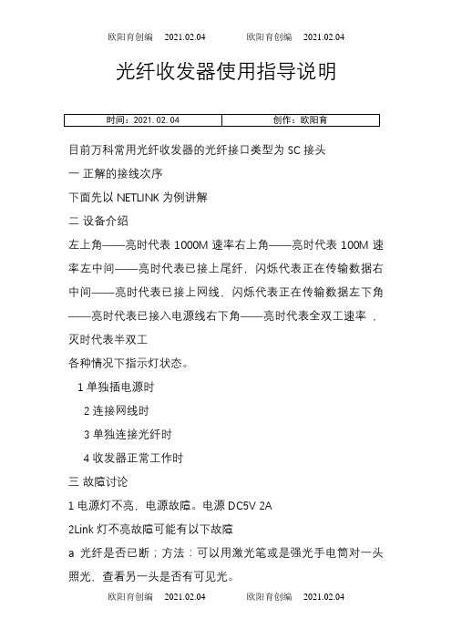
光纤收发器使用指导说明目前万科常用光纤收发器的光纤接口类型为SC接头一正解的接线次序下面先以NETLINK为例讲解二设备介绍左上角——亮时代表1000M速率右上角——亮时代表100M速率左中间——亮时代表已接上尾纤,闪烁代表正在传输数据右中间——亮时代表已接上网线,闪烁代表正在传输数据左下角——亮时代表已接入电源线右下角——亮时代表全双工速率,灭时代表半双工各种情况下指示灯状态。
1单独插电源时2连接网线时3单独连接光纤时4收发器正常工作时三故障讨论1电源灯不亮,电源故障。
电源DC5V 2A2Link灯不亮故障可能有以下故障a光纤是否已断;方法:可以用激光笔或是强光手电筒对一头照光,查看另一头是否有可见光。
b光纤线路损耗过大;用工程宝的测光功率计仪表检测。
光纤收发器或光模块在正常情况下的发光功率:单模20公里:-8DB—15DB之间;如果在光纤收发器的发光功率在-30DB――45DB之间,那么可以判断这个收发器有问题。
C 光纤插头是否插反d.跳线类型与设备接口匹配3网络丢包严重可能故障如下:a收发器的电端口与网络设备接口,或两端设备接口的双工模式不匹配。
b双绞线与RJ-45头有问题。
c光纤连接问题,跳线是否对准设备接口,尾纤与跳线及耦合器不匹配4时通时断现象a可能为光路衰减太大,此时用光功率计测量接收端的光功率,如果在接收灵敏范围附近1-2DB之内可基本判断为光路故障;b可能是交换故障,把交换机换成PCc 可能为收发器故障,把收发器两端接PC(不通过交换机),两端对PING没问题后,从一端向另一端传送一个较大文件(100M)以上,观察速度,如果速度慢(200M以下的文件传送15分钟以上),可基本判断为收发器故障。
5通信一段时间后死机,断电后恢复。
此情况一般是交换机引起,6收发器RJ45口与其他设备连接时,中间有交换机设备时使用平行双绞线;直接连设备后,使用交叉双绞线;7Txlink 灯不亮A双绞线接错 B 水晶头接触不良C设备没正常连接8Txlink灯不闪烁却常亮传输距离过长或是直接与PC连接时兼容问题9 指示灯正常但无法传输断电重启。

Rev 0505 High Gain Omni-Directional Antenna User Guidefor Models:WI-ANT-P6 Omni-Directional 6 dBd Pole remote antennaWI-ANT-P6-A-10 Omni 6 dBd remote antenna w/lightning arrestor & 10 ft cableWI-ANT-P6-A-25 Omni 6 dBd remote antenna w/lightning arrestor & 25 ft cableAccutech High Gain Omni-Directional Remote Antenna User Guide Rev 0505______________________________________________________________________________________________________________________________________A Division of Adaptive Instruments Corp.577 Main Street · Hudson, MA 01749 U.S.A.TE L:800-879-6576·978-568-0500FAX:978-568-9085Email:*******************************Rev Date Notes InitialsRelease TH1.0 1/17/2005TH0505 05/17/2005 Updated format, changedan installation picture.AccutechA Division of Adaptive Instruments Corp.577 Main Street · Hudson, MA 01749 USATEL: 800-879-6576 · 978-568-0500FAX: 978-568-9085Email: *******************************Web: Accutech High Gain Omni-Directional Remote Antenna User Guide Rev 0505Table of Contents1.ABOUT THE HIGH GAIN OMNI-DIRECTIONAL ANTENNA (1)2.INSTALLING THE HIGH GAIN ANTENNA WITH THE LIGHTNING ARRESTOR (2)2.1.Package Contents (2)2.2.Antenna & Lightning Arrestor Connection (3)3.INSTALLING THE HIGH GAIN ANTENNA (6)3.1.Package Contents (6)3.2.Antenna Connection (7)4.TECHNICAL SPECIFICATIONS (9)4.1.High Gain Omni-Directional Antenna (9)4.2.Mounting bracket dimensioned drawing (10)Accutech High Gain Omni-Directional Remote Antenna User Guide Rev 0505Accutech High Gain Omni-Directional Remote Antenna User Guide Rev 05051. About the High Gain Omni-DirectionalAntennaHigh gain and remote antennas can increase the transmission distanceof the Accutech Wireless Sensors. For even greater transmissiondistance, a high gain directional antenna (Yagi) may be purchased as anintegral part of a field unit.Warning! Any Base Radio with an omni-directional antenna is forordinary locations only.This manual will guide you through the steps to connect a High GainOmni-Directional Antenna with or without a lightning arrestor to a BaseRadio. If you are using a lightning arrestor, go to section 2. If you are notusing a lightning arrestor, go to section 3.The following model numbers are covered in this guide:Remote AntennasWI-ANT-P6 Omni-Directional 6 dBd Pole remote antennaWI-ANT-P6-A-10 Omni 6 dBd remote antenna w/lightning arrestor & 10 ft cableWI-ANT-P6-A-25 Omni 6 dBd remote antenna w/lightning arrestor & 25 ft cableEach of the above High Gain Remote Antenna models can be used withany of the following Base Radio model numbers:Base RadiosWI-BR-R10-4XN EMA 4X Base Radio w/10 ft cable and RS-485 output for rmt antenna WI-BR-R10-4X-MOD NEMA 4X Base Radio w/10 ft cable, RS-485 & Modbus, for rmt antenna WI-BR-R25-4X NEMA 4X Base Radio w/25 ft cable and RS-485 output for rmt antenna WI-BR-R25-4X-MOD NEMA 4X Base Radio w/25 ft cable, RS-485 & Modbus, for rmt antenna1Accutech High Gain Omni-Directional Remote Antenna User Guide 05052. Installing the High Gain Antenna with theLightning ArrestorThis section will show you how to install the high gain antenna with thelightning arrestor. If you are not using the lightning arrestor, go to Section3. For additional information about the Base Radio see the Base RadioUser Manual. Any of the Base Radio model numbers mentioned insection 1 may be used with the following remote antenna models:WI-ANT-P6-A-10 Omni 6 dBd remote antenna w/lightning arrestor & 10 ftcableWI-ANT-P6-A-25 Omni 6 dBd remote antenna w/lightning arrestor & 25 ftcable2.1. Package ContentsThe high gain Omni 6 dBd antenna with the lightning arrestor kit comescomplete with:[1] High gain antenna pole[2] 2 Mounting brackets for the high gain antenna[3] Lightning arrestor assembly consisting of lightning arrestor and 10’of 10 AWG ground wire[4] Coaxial cable assembly attached to the l ightning arrestor:10’ length for WI-ANT-P6-A-1025’ length for WI-ANT-P6-A-25[5] Waterproofing material for the antenna coaxial connectionT he following comes attached to the Base Radio:cableassembly:[6] Coaxial10’ length for WI-BR-R10-4X and WI-BR-R10-4X-MOD25’ length for WI-BR-R25-4X and WI-BR-R25-4X-MODAccutech High Gain Omni-Directional Remote Antenna User Guide Rev 0505 22.2. Antenna & Lightning Arrestor ConnectionAttention!For installation inordinary locations only!Antenna connected to Lightning Arrestor and Base Radio3Accutech High Gain Omni-Directional Remote Antenna User Guide 0505Warning! Always use caution when installing this antenna. You canbe seriously injured if this antenna comes near or in contact with apower line. Follow all local and national electrical coderequirements when installing the Base Radio with the high gainantenna.[1] Select the locations for the high gain antenna, the lightningarrestor and Base Radio.It is recommended that the lightning arrestor be mounted in closeproximity to the building egress. The lightning arrestor should bemounted indoors unless you have the weatherproof enclosure.The location for the high gain antenna should be selected basedon optimal positioning for RF communications with the field unitsand allow for sufficient length of coaxial cable to reach the buildingegress.The Base Radio should be installed in a location where there issufficient coaxial cable available to reach the building egress.Warning! Any Base Radio with an omni-directional antenna is forordinary locations only.[2] P osition the antenna sothat the gold sleeve clearsany obstructions. Thisincludes masts and towersections.[3] Mount the antenna usingthe 2 mounting brackets.One clamp must beplaced at the center of thegold sleeve, the other atany point below.[4] Connect the Base Radio coaxial cable to the lightning arrestor andtighten by hand.[5] Attach the ground wire to a suitable earth ground connection. Keepthis wire as short as possible. Make sure this connection conformsto electrical code requirements.[6] Connect the lightning arrestor coaxial cable to the antenna andhand-tighten.[7] Install a drip loop in the cable to insure proper drainage.Accutech High Gain Omni-Directional Remote Antenna User Guide Rev 0505 4[8] Wrap the antenna connection with the supplied waterproofingmaterial.Note Do not cover the drain holes on the bottom of the antenna asthey provide drainage for moisture.[9] Finished.5Accutech High Gain Omni-Directional Remote Antenna User Guide 05053. Installing the High Gain AntennaThis section will show you how to install the high gain antenna without alightning arrestor. If you are using a lightning arrestor, go to section 2.For additional information about the Base Radio see the Base RadioUser Manual.Warning! This configuration is for indoor use only. If you aremounting the antenna outdoors, a lightning arrestor must be used.Any of the Base Radio model numbers mentioned in section 1 may beused with the following remote antenna model:WI-ANT-P6 Omni-Directional 6 dBd Pole remote antenna3.1. Package ContentsThe high gain Omni 6 dBd antenna kit comes complete with:[1] High gain antenna pole[2] 2 Mounting brackets for the high gain antenna[3] Waterproofing material for the antenna coaxial connectionT he following comes attached to the Base Radio:assembly:[4] Coaxialcable10’ length for WI-BR-R10-4X and WI-BR-R10-4X-MOD25’ length for WI-BR-R25-4X and WI-BR-R25-4X-MODAccutech High Gain Omni-Directional Remote Antenna User Guide Rev 0505 63.2. Antenna ConnectionAttention!For installation inordinary locations only!Antenna connected to Base Radio7Accutech High Gain Omni-Directional Remote Antenna User Guide 0505Warning! Always use caution when installing this antenna. You canbe seriously injured if this antenna comes near or in contact with apower line. Follow all local and national electrical coderequirements when installing the Base Radio with the high gainantenna.[1] Select the locations for the high gain antenna and Base Radio.The location for the high gain antenna should be selected basedon optimal positioning for RF communications with the field units.Warning! Any Base Radio with an omni-directional antenna is forordinary locations only.[2] Position the antenna sothat the gold sleeve clearsany obstructions. Thisincludes masts and towersections.[3] Mount the antenna usingthe 2 mounting brackets.One clamp must beplaced at the center of thegold sleeve, the other atany point below.[4] Connect the Base Radio coaxial cable to the antenna and hand-tighten.[5] Install a drip loop in the cable to insure proper drainage.[6] Wrap the connection with the supplied waterproofing material.Note Do not cover the drain holes on the bottom of the antenna asthey provide drainage for moisture.[7] Finished.Accutech High Gain Omni-Directional Remote Antenna User Guide Rev 0505 84. Technical Specifications4.1. High Gain Omni-Directional AntennaBase Radio High Gain Omni-Directional AntennaLength65”Gain 6 dBd (less cable loss ≈ 0.04 dBd/ft)Weight 6 lbsPolarization VerticalMounting Heavy wall gold anodized 1 ¼” aluminum withbrackets included10’ or 25’Base Radio coaxialcable length9Accutech High Gain Omni-Directional Remote Antenna User Guide 05054.2. Mounting Bracket Dimensioned DrawingMounting bracket dimensioned drawingAccutech High Gain Omni-Directional Remote Antenna User Guide Rev 0505 10______________________________________________________________________________________________________________________________________ A Division of Adaptive Instruments Corp.577 Main Street · Hudson, MA 01749 U.S.A.TE L: 800-879-6576 · 978-568-0500FAX: 978-568-9085Email: ******************************* Accutech, a division of Adaptive Instruments Corp., is a leading edge,technology-driven developer, manufacturer and supplier of embeddedmicroprocessor-based electronics. Based in Hudson, Massachusetts,Accutech is the most successful leading independent producer ofwireless instrumentation on the market today.Accutech customers include large national companies in the oil andgas, chemicals, pharmaceutical, food and beverage, primary materialsprocessing, and energy industries. In addition to the wireless productline, Accutech also offers a traditional wired line of temperature,pressure and differential pressure instrumentation.In the process control field, where quality is taken for granted and newtechnology is announced daily, we have deliberately concentrated ourefforts on the development of instrumentation that makes businesssense. The result is a product range that is rugged, secure, andreliable and works in even the most hazardous environments. We givecompanies the tools to reduce costs, save time, enhance safety,improve environmental performance and cut waste.The next industrial revolution is right now. Let Accutech show you howto realize gains in operating efficiency.Visit us at: Or call us at +1 800 879-6576 Specifications subject to change without notice. Printed in USA. Copyright 2005 Adaptive Instruments, Corp.。
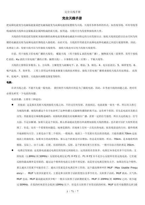
完全天线手册把高频电能变为电磁场能量或把电磁场能变为高频电能的装置称为天线。
天线有各种各样的形式,如直线导线、环形导线等构成的线天线和由金属板或金属网构成的面天线。
按用途,天线可分为发射和接收两大类。
天线的作用就是把发射机末级回路的高频电流变换成电磁波并向特定的方向发射出去。
接收天线则是把以自由空间为传媒的电磁波还原为高频电流经馈线送入接收机。
由此可见,天线的作用就是在高频电流和电磁波之间进行能量转换。
因此,从理论上讲,发射天线可以当作接收天线使用,接收天线也可以充当发射天线使用。
目前,用于接收卫星电视广播的天线有:螺旋天线(用于接收L波段电视广播)、抛物面天线(前馈型。
常用于接收C波段、Ku波段卫星电视广播的正馈、偏馈天线)、卡塞格伦天线(后馈)、平板天线等。
天线的主要特征参数有:1、方向图、主瓣宽度与副瓣电平;2、增益;3、极化;4、电压驻波比;5、频带宽度;6、噪声温度;7、效率等。
工程上常用这些参量来衡量天线的技术特征。
接收卫星电视广播要求接收天线具有高增益、高效率、低噪声、宽频带、天线指向调整范围宽等特性。
电波:在讲天线之前,不能不先提一提电波。
我们制作天线的目的是为了捕捉电波,因此,在考虑天线的问题之前,绝对有必要先研究一下电波的问题。
电波传播,主要有三种途径:●直接波: 这是指从发射天线到接收天线之间,不经过任何发射,直接到达,电波就象一束光一样,所以有人称它为视线传播。
视线传播这个名字也表明了这种传播方式能够传播的距离不远。
这有两个原因,首先是电波从发射点出发,其能量是以幂级数递减的,而接收机要能良好地解调出广播,需要一定的信号强度。
所以太远的地方,信号太弱,不足以解调。
如果只是这个原因,那么拼命提高发射功率或增加接收天线的增益,也许就可以扩大收听的范围了。
但是,还有一个重要的问题是,地球是圆的,在地球上任何一点发出的电波,按直线前进的方向,最终将离开地球射向天空。
主要是由于第二个原因,一般地讲,地面上一个发射台发出的直线波,只能传播到70km远处地面上的接收处。

3207型号天线系统设置和用户手册The World Leader inSubsurface Imaging™美国劳雷工业有限公司目录3207型天线 (3)3207P和3207AP操作注意事项 (4)1.理解电子单元 (4)2.操作模式 (6)2.1双体天线浅部探测模式 (6)2.2双体天线深部探测模式 (7)2.3单体天线(3207AP) (8)3仪器部件和连接装置图 (10)3.1部件列表 (10)3.2硬件连接图 (11)4距离测量选项 (12)5软件系统设置--标准设置 (14)5.1 3207AP单体天线参数设置 (14)5.2 3207P双体天线参数设置 (15)5.3 天线参数 (15)附图3207型天线3207型号天线用于深部探测,可有效对地下土壤和岩石结构成图。
3207型天线有2种组成方式。
单体方式:有单个天线3207盒子构成,包括一个769DA2发射/接收电子单元,即每个电子单元电路板上设置了发射和接收切换开关。
鉴于该天线仅仅有一个3207盒子,需要进行深部探测而场地范围又小的情况下,单体天线是一个理想选择。
这种形式天线定义为3207AP。
3207天线对,用于深部探测、共中心点CMP分析。
包括两个3207盒子,中间通过玻璃纤维竿子连接,或者采用不通的间距用于CMP 测量分析。
一个盒子用于发射天线,另外一个盒子用于接收天线。
接收天线采用769DA2型号电子单元,仅仅用于接收电磁波,通过out 输出端口连接至发射天线电子单元。
发射天线采用778型号高功率发射电子单元,通过一个电缆连接至769DA2。
无论记录长度大小,都可以使用3207天线对测量。
这种天线形式定义为3207P。
注意:570型号光缆发射连接器用于3207P天线对。
570型号光缆发射器用于取代同轴电缆。
利用570型号部件可以取得更好的探测效果。
建议单独购买570型号光缆。
3207型号天线中心频率为100MHz。
GSSI公司强烈建议在使用SIR-3000和100兆天线对时使用570型号光缆发射器。

MANUAL INSTRUCCIONESPOR FAVOR LEA TODAS LAS INSTRUCCIONES ANTES DEL MONTAJECARACTERÍSTICAS1.Bibanda 2m/70cm.2.El tipo de elemento independiente garantiza una buena ganancia y rendimiento en comparacióncon monobandas.3.Boom, elementos y soportes de acero inoxidable que garantizan una durabilidad superior y unavida útil prolongada en todas las condiciones climáticas.4.Ligero, compacto y fácil de instalar y volver a montar.ESPECIFICACIONESTipo ............................................... Y agi, 3 elementos 144 MHz,, 5 elementos 430 MHzFrecuencias .................................... 144-146 / 430-440 MHzPotencia máxima ........................... 50 W (FM)Impedancia .................................... 50 ΩRelación FB .................................... > 12dBLongitud boom .............................. 113 cm.Conector ........................................ S O239Diámetro mástil ............................. 30 – 55 mmPeso ............................................... 870 grs.MONTAJE1.Identifique y organice los 8 elementos y la unidad de alimentación de la antena.Consulte la tabla de colores.e una arandela plana y una tuerca de mariposa para cada elemento y la unidad de alimentación (con Raa yRab) de acuerdo con el código de color al boom.3.Inserte la varilla de ajuste A y B en la unidad de alimentación.La varilla A (larga) debe estar en el orificio más alejado del conector SO239. La varilla B (corta) debe estar en el orificio más cercano del conector SO239. Con la llave hexagonal que se proporciona, apriete las varillas en la unidad de alimentación con los tornillos de fijación. Adjunte barras de cortocircuito según el diagrama.4.Consulte el dibujo y coloque la abrazadera del cable en el boom hacia adelante desde la ubicación del soportedel perno en U y en el mismo lado que la unidad de alimentación eléctrica..5.Monte la antena en el mástil en posición horizontal o vertical (desplace la antena si es necesario cuandoutilice un mástil de metal; consulte el diagrama).6.Conecte el cable coaxial con el conector PL259 a la unidad de alimentación e inserte el cable coaxial en laabrazadera. Use cinta aislante o ataduras de cables para asegurar el cable coaxial a lo largo del boom. AJUSTE R.O.E.1.Ajuste la ROE en la frecuencia central de cada banda. Mueva la barra de cortocircuito más lejos del conectorpara aumentar la frecuencia central donde la ROE es óptima.2.Asegúrese de que las tuercas de mariposa estén apretadas en la barra de cortocircuito.。

天线控制系统使用维护说明书1.引言2.系统安装2.1环境选择在安装天线控制系统前,需要选择一个适合的环境。
优先选择平坦、无障碍、低振动和低电磁干扰的地点。
2.2定位安装使用专业工具将天线固定在地上或建筑物上。
确保天线安装牢固,不易受风力和震动影响。
2.3连接设备将天线与控制系统主机通过合适的接口连接。
确保连接牢固可靠,避免松动导致数据传输错误。
3.系统操作3.1系统启动打开控制系统主机电源,确保其正常启动。
根据系统要求登录主机,并进入系统操作界面。
3.2参数设置在操作界面上,根据具体的需求设置系统的参数。
包括天线指向、运动速度、增益控制等。
确保参数设置正确,避免误操作导致天线运动错误。
3.3运动控制使用控制器手柄、键盘或鼠标控制天线的运动。
根据需求调整天线的方向和角度。
注意避免超过天线的运动范围,避免发生意外损坏。
3.4数据获取控制系统可读取和提供天线所接收到的数据。
在接收数据前,确保天线与接收设备正确连接。
根据需要选择数据获取方式,并进行相应的操作。
3.5系统关闭在操作完成后,关闭控制系统主机电源。
根据系统要求进行正常的关机程序。
确保系统关闭后,再进行下一步操作。
4.系统维护4.1清洁保养定期清洁天线和控制系统主机,以防止灰尘和污垢积聚。
使用干净的软布轻轻擦拭,避免使用带有化学物质的清洁剂,以免损坏设备。
4.2检查维修定期检查天线固定件、连接线缆和接口是否松动或损坏。
如有发现问题,及时进行维修或更换,避免影响系统的正常运行。
4.3软件升级根据制造商提供的软件升级通知,定期更新天线控制系统的软件。
升级前备份现有数据,并按照升级指引进行操作。
确保系统保持最新的功能和安全性。
4.4故障排除5.总结。
电子天线使用说明书一、产品概述电子天线是一种用于接收和发射电磁信号的设备,用于接收和传输无线电、电视、卫星和无线通信等信号。
本使用说明书旨在帮助用户正确使用电子天线,以达到最佳的信号接收效果。
二、产品组成1. 主体:由天线罩、电路板和连接线组成;2. 天线罩:用以保护并增强天线的接收和传输性能;3. 电路板:包含天线信号处理电路和连接接口。
三、使用步骤1. 连接电源:将电源线插入电源插座,并将电源插头插入电子天线的电源接口;2. 连接信号源:根据需要,选择相应的接口连接电视、电台或其它设备,确保连接稳定;3. 调整天线的方向:将电子天线放置在合适的位置,确保天线罩朝向信号源的方向;4. 搜索信号:在电视或设备的菜单中,选择自动搜索信号功能,等待搜索完成;5. 完成设置:根据信号搜索结果,完善设备的信号设置,并根据需要进行调整。
四、注意事项1. 安装位置:电子天线最好放置在接收信号最佳的位置,避免阻挡或干扰天线的信号接收;2. 稳定连接:使用连接线时请确保插头插紧,连接稳定,避免信号中断或质量下降;3. 室内使用:电子天线主要用于室内使用,如果需要室外使用,请确保防水措施;4. 信号调整:如果信号接收不理想,可以尝试调整天线的位置或方向,或使用信号放大器进行增强;5. 保养维护:请定期清洁电子天线,保持天线罩的干净,以提高信号接收效果。
五、故障排除1. 无信号:请检查信号源是否正常工作,确认连接线是否插紧,信号接口是否正确;2. 信号质量差:请检查天线的位置和方向,尝试调整天线的角度或位置,或使用信号放大器;3. 无法搜索到信号:请检查设备的信号设置是否正确,或尝试重新搜索信号。
六、免责声明1. 本产品仅适用于合法的无线电接收和传输应用,禁止用于非法用途;2. 用户在使用本产品时需遵守当地的无线电法规和相关规定;3. 由于用户的不当使用或违规操作所引起的问题和责任,本公司概不负责;4. 如有任何疑问或问题,请联系售后服务部门。
T H E E-Z I N E F O R F R U G A L A U D I O E N T H U S I A S T S Affordable $$AudioIssue Number 45: September 2009Magnum Dynalab Indoor FM Antenna'sBy Anthony Nicosia**********************************SpecificationsSR-100 Silver Ribbon Tunable FM AntennaAn indoor Antenna for both enhanced FM performance and HDTV broad-castsSpecificationsBase measures 3.5” width x 2.5” deep x 3/4” highMaximum height of antenna fully extended: approx. 37.5”Maximum width of antenna fully spread: approx. 32”Cord is approx. 3' longWarranty: twenty four month limited warranty applies to the first end userPrice: $35MD-205 Signal Sleuth FM signal AntennaAccording to Magnum Dynalab “In an independent test, using a commer-cially available FM tuner, the following percentile improvements were at-tained with the SLEUTH on line:Sensitivity (under 1dB limiting) -170%Spurious Response Rejection -90%Image Rejection -380%Ultimate Sensitivity was rated at 70dB+Also, the total harmonic distortion (THD) re-mained unchanged indicating the Sleuthadded no measurable distortion of its own.”SpecificationsCircuit: 3 varactor-tuned RF stagesGain: VARIABLE -30dB thru +30dBTuning Range: 88-110 MHzBandwidth: Better than 400KHzNoise: Less than 4dBDistortion: 0%Antenna Input: 75 ohmsPower Required: 230/240/110 voltsSize: 17” x 1.75' x 6”43.18cm x 4.45cm x 15.24cmWeight: 6 lbs/ 2.65KGWarranty: twenty four month limited warranty applies to the first end userPrice: $435Company InformationMagnum Dynalab Ltd.8 Strathearn Avenue, Unit 9Brampton, OntarioCanadaL6T 4L9Telephone: (905) 791-5888Toll free in North America 1-800-551-1430Fax: (905) 791-5583International Fax: (1) (905) 791-5583US Contact Telephone, toll free: 1-800-551-4130Web address: Email address: **********************L ooking back twenty-five years ago to 1984, we see a time when Magnum Dynalab introduced its very first product, the Signal Sleuth, which was designed to boost and stabilize FM signals. According to Larry Zurowski, the president of Magnum Dynalab, the biggest difference between that Signal Sleuth and today’s model is that the gain curve is now more consistent across the FM band. Later, in September of 1985, the company marketed the FT 101, which was her-alded as their first FM tuner. Magnum Dynalab now makes FM tuners, an integrated FM receiver, an integrated ampli-fier as well as a selection of both indoor and outdoor antennas. Having recently, in the June 2009 issue of “AffordableAudio”, taken a look back at the 1960's McIntosh MR67 tube tuners I can only wish I’d had today’s Magnum Dynalab products around to help with the review.I have, as of late, been using a TERK FM+ Indoor Antenna, which was recommended to me by a friend. Unfortunately, I live in a more difficult environment than his, and while this inexpensive antenna priced at only $9.99 worked better than no antenna it still left me with a desire for something more substantial. When I first contacted Larry Zurowski I was completely upfront with him in explaining that I lived in an area that has great difficulty getting a proper reception. I explained that I am situated at the bottom of a very high steep hill where FM reception is poor, even when it comes to capturing local stations. Add this to the fact that there are large commercial planes flying relatively low, from the San Francisco airport, and you have an FM reception nightmare. Larry never addressed this issue, but rather sent me an email saying he would send the requested products as soon as he could get me an SR-100 Silver Ribbon Tunable FM Antenna, which were at the time on backorder. A few weeks latter both the SR-100 and Signal Sleuth arrived neatly packaged and in perfect condition.To tell you the truth I did not expect very much in the way of an improvement with the SR-100 antenna as I was al-ready using an indoor antenna for my MR-67 tuner. Having tried a variety of other indoor style antennas I never did have much luck picking up stations and was resigned to the fact that I must go the outdoor antenna route. After all this was only a thirty-five dollar investment, how much of a difference would it make being that I live in a difficult FM recep-tion area? As it turned out, it made a huge difference. I was floored with the vast improvement this indoor antenna made and had to put my own antenna back in just to see if maybe the moon and stars were aligned differently that day and had somehow cleared the skies for superior FM reception. But no, switching back to my original antenna resulted in a poorer performance once again that allowed for some stations to drift and others to be difficult to pull in properly. After reinserting the SR-100 I found everything to be right once again. I was sold and spent the rest of the morning listening to music via my newly revamped FM tuner setup. With the SR-100 I was able to pull in stations that before were “edged” with static but now were quite silent. I felt a greater depth to the music as this silent background now af-forded me a clearer window with which to hear through, and I enjoyed each musical performance anew. Whereas be-fore I would glide the tuning knob through the various frequencies to hear plenty of static, now for the most part there was silence. It was not so much that it pulled in stations that I could not capture before but rather for me it made the stations I was already receiving sound clearer and more powerful. I liked what it brought to my system as it quite sim-ply did the job it was intended to accomplish and did so for the paltry sum of only thirty-five dollars. Having had other “rabbit ear” style antennas in my listening room before, I must say that my wife finds them quite unattractive, but not so with the SR-100. Its combination of mostly black and silver (an Oakland Raiders fans delight, yes we live less than an hour from their stadium) coupled with its slender simple appearance worked just fine for us from an aesthetics point of view.OperationNow in steps Magnum Dynalab's MD-205 Signal Sleuth FM signal Antenna. Take note that the Sleuth’s performance will be directly related to the quality of the antenna attached, as well of course as the reception within the area and the attributes of the tuner used in conjunction with it. It is a tunable RF processor for FM stations across the 88-108 MHZ frequency bandwidth. I naturally used Magnum Dynalabs own SR-100 Silver Ribbon antenna for this evaluation but as previously stated you might even want to try one of their more powerful outdoor antennas for a more “startling” experi-ence. I say startling because that is what this combination of SR-100 and MD-205 felt like to me. For a complete in-structional aide of how to set-up the MD-205 please read the owners manual, but for now let me give you a quick summation of the process which may at first seem a little complicated. With your purchase you will be supplied with a patch cord with 'F' connectors on both ends. Connect the FM tuner to the MD-205 via this patch cord to the area marked “Output to Tuner”. Connect the MD-205 to your antenna by way of the connector labeled “Antenna Input”. Please make sure that both switches located on the front of the MD-205 one labeled “Power”, is in the off position, the other “Antenna Signal”, is in the Bypass position. The FM tuner should also be turned off. Now use the supplied fac-tory power cord to plug the unit into an outlet. Be very careful as “Significant damage will be done to the unit if the wrong voltage is applied”. Appropriate voltage should be marked on the back of the unit. Alright, now turn on the MD-205 by moving the power switch to the “ON” position and then switch the antenna signal switch to the “Amplify” posi-tion making sure that all the LED lights turn on with each flip of the switch. Now that it is connected and functioning properly let me explain how to use the Sleuth when dialing in different radio stations, in order to help you tune them in for better reception.The following should be performed with the tuner's Mute switched “OFF” and the Sleuth's RF Gain control fully turned in the counter-clockwise position past where a 'click' is heard. First turn on the Sleuth with the Antenna Signal switch set to bypass, then turn on your FM Tuner. Make sure that the tuner is set to stereo. Tune to a station that has a fairly strong signal in your area and then set the Sleuth's tuning control to the same approximate frequency. There is no digi-tal readout for this, so you have got to trust what we used to do before digital readout, look with your own eyes and listen with your own ears. Now you can switch the Antenna Signal switch to the 'Amplify' position. As you then rotate the RF Gain control to fully clockwise and you will start to feel a click. Looking at the signal strength on the tuner you will rotate the Sleuth's Tune control until you find the highest reading on the signal strength meter, or until you perceive the clearest audio signal. Switching back to the RF Gain control, now rotate it counterclockwise until you get a weaker signal and then rotate it back clockwise until the audio signal is at its optimum. It is now time to turn the Mute switch to the 'ON' position. When you need to switch frequencies on your tuner simply turn the Antenna switch on the Sleuth to the 'bypass' position then tune your FM Tuner to the next desired station. Turn the Sleuth to the corresponding fre-quency, turn the Antenna switch back to amplify and rotate the Gain control and the Tuning Knob on the Sleuth to re-gain optimal signal strength or until it sounds best to your own ears.ImpressionsOnce again this Magnum Dynalab product impressed me with its ability to do exactly what it was designed for. It sepa-rated weaker stations by allowing you to finely tune them in and then boosted their signal with up to 30dB of gain, thereby adding power to the selected frequency. The affects of the Sleuth reminded me of a Vinyl pressed Master Re-cording where music would seem to spring forth from a background of dead silence, quite impressive indeed. As the Sleuth tuned in radio station after station, using the units gain control knob to put on the finishing touches, I was al-ways amazed at how the stations snapped into focus allowing me to hear music as if I had purchased a much more expensive tuner. The only two regrets I had concerning my review of the Sleuth were that I was not using one of their outdoor antennas, to see how good my MR67 tuner could actually be, and secondly that I was not using a modern day tuner made by Magnum Dynalab.ConclusionBoth the SR-100 Silver Ribbon antenna and the MD-205 Signal Sleuth FM signal Antenna added no coloration of their own to the sound, yet they did have an enormous affect on the musical performances heard through them. I suggest that both be used together in order to realize the full potential of each. The SR-100's job is to capture local FM radio stations and is an excellent alternative for audiophiles who do not want to install an outdoor antenna or those of us on a more stringent budget. It is tunable, to maximize FM reception, and, as my wife and I found, quite attractive. The Sleuth on the other hand is a device designed to tune in the weaker FM radio stations in your area, separate them from the stronger ones and add up to a 30dB boost of gain to the appropriate signal. While it is in itself no substitute for a good tuner or antenna it will enhance their performance by its ability to add three RF stages and power to the signal. Using them both together I found the quality of my FM reception vastly expanded while my listening pleasure increased immeasurably. FM broadcasts tuned in easily and the added background silence was indeed a welcome addition. Both products are very highly recommended.The Listening Environment:The review room is eighteen feet eight inches long by thirteen feet wide. The loudspeakers and equipment are kept on the short wall. The cathedral ceiling starts at eight feet and sloops upwards to thirteen feet at its peak in the middle spanning across the short length of the room for the full thirteen feet height. The hardwood floor has a nine by six foot oriental rug lying down the long ways toward the system placed dead center in between, yet not under, the listener and the review equipment The room has no doors, but has two openings. One is in front of the right Legacy Focus 20/20 loudspeaker, which gives access to the hallway while the other is behind the listening position and opens to the formal dinning area. The room is treated with two floor standing acousti-cal panels, one behind each speaker, and the audio equipment is located in a Cherry Synergy Twin S30 Salamander audio rack against and in the middle of the short wall. I have two power conditioners that plug into a PS Audio Power Port receptacle located behind the audio rack. There are also two Blue Circle Audio MKIII Power Line Pillows, one on each of two outlets on the long walls next to and behind each loudspeaker. The Legacy speakers are located about six feet seven inches from the rear wall to their front panel. They are also twenty one inches from the rooms side walls to the middle of each loudspeakers. The Legacy's are twelve feet apart from each other to form a triangle with the listening position that is also angled at twelve feet from loudspeaker to listener. In the corner of each short wall behind the Legacy's are a pair of 1989 Klipsch Klipschorn loudspeakers that are some-times used for reviews. If the Klipsch loudspeakers are used I would then reposition the two acoustical panels to slightly behind the listening position one to the left and the other to the right of it.Review Equipment:McIntosh MR67 Tube Tuner and matching wood cabinet with slant legsMonarchy Audio SM-70 Pro power amplifiers (2 used in mono block configuration), Monarchy Audio M24 Preamplifier, Samsung HD-841 Cd/SACD/DVD Audio universal player, Oracle Delphi MK I turntable, Grace 707 tonearm and Denon DL-301MK II Moving Coil stereo cartridge, Whest Phonostage.20 + MsU.20 power supply(for Moving Coil or Moving Magnet cartridges)PS Audio power port receptacle, Two Blue Circle Audio Mk III power line conditioners, Acoustic Revive RTP-4 Series power con-ditionerm, Kimber Kable 4TC loudspeaker cable with matching jumper wires, Kimber Kable Hero and Tonik InterconnectsTek Line, PC-8 Signature power cords, two six foot lengths, Mr. Cable,The Musician power cord, a nine foot lengthMonarchy Audio AC-1 power cord, two six foot lengths, Cherry Synergy Twin S30 Salamander audio rack。
电视天线-简易说明参考(兰起双模)
1.同轴电缆F头连接
2.锅组装完正面
3.锅组装完背面
4.锅背面调整组架
5.锅面简易固定
6.高频头夹具
7.头、夹具连接
8. 1锅1机极化角A
9.1锅多机极化角B 10.1锅多机极化角C
11.左旋11880 12.右旋12100 13. 右旋12140 14.菜单15.系统设置
QQ:852427001 全部配件保换不保修,自购买日起三个月内保换。
16.默认设置17.密码0000、9999 18.搜索节目19.手动单频点搜索
20.搜索11880 21.搜索12100 22.搜索12140
说明:1.按照图1-8组装天线(一锅一机,有极化片),图9、10适用特殊用户!(一锅多机,无极化片)。
2.锅面对西南方、固定、连接、开机,按遥控器“F3”键,电视机显示11、12、13图片之一,
未对准卫星则信号质量为0%,精准对星后各频点信号质量为70%左右。
(非中九切换:蓝、红、红、红、红,确定)3.新机子出厂时默认最新数据,不用搜索,只要对星成功后即可正常观看。
如因意外、早期出厂等原因,机子数据非最新等,可参考图14至22、“确定”快速手动搜索或恢复出厂设制后,关机、开机,机子会自动慢速盲扫描。
4-port sector antenna, 4x 2300–2700 MHz, 65° HPBW, 2x RET withmanual overrideIntegrated Internal Remote Electrical Tilt (RET), with independent control of electrical tilt withmanual override on all arraysGeneral SpecificationsAntenna Type SectorBand Single bandGrounding Type RF connector inner conductor and body grounded to reflector andmounting bracketPerformance Note Outdoor usage | Wind loading figures are validated by wind tunnelmeasurements described in white paper WP-112534-ENRadome Material Polyester fiberglass pultrusionRF Connector Interface7-16 DIN FemaleRF Connector Location BottomRF Connector Quantity, high band4RF Connector Quantity, total4Remote Electrical Tilt (RET) InformationRET Interface8-pin DIN MaleRET Interface, quantity 1 maleInput Voltage10–30 VdcInternal RET High band (2)Power Consumption, idle state, maximum 2 WPower Consumption, normal conditions, maximum13 WProtocol3GPP/AISG 2.0 (Single RET)DimensionsWidth300 mm | 11.811 inDepth115 mm | 4.528 inLength1077 mm | 42.402 inNet Weight, without mounting kit13 kg | 28.66 lb15Page ofPage of 25Port ConfigurationElectrical SpecificationsImpedance50 ohmOperating Frequency Band 2300 – 2700 MHz Polarization±45°Electrical SpecificationsFrequency Band, MHz 2300–25002500–2700Gain, dBi17.217.8Beamwidth, Horizontal, degrees 6563Beamwidth, Vertical, degrees 7 6.5Beam Tilt, degrees 0–100–10USLS (First Lobe), dB1818Front-to-Back Ratio at 180°, dB 3030Isolation, Cross Polarization, dB 3030VSWR | Return loss, dB 1.43 | 15.01.43 | 15.0PIM, 3rd Order, 2 x 20 W, dBc-150-150Input Power per Port, maximum, watts250250Mechanical SpecificationsWind Loading @ Velocity, maximum450.0 N @ 160 km/h (101.2 lbf @ 160 km/h) Wind Speed, maximum200 km/h (124 mph)Packaging and WeightsWidth, packed366 mm | 14.409 inDepth, packed213 mm | 8.386 inLength, packed1260 mm | 49.606 inWeight, gross21.5 kg | 47.399 lbRegulatory Compliance/CertificationsAgency ClassificationCHINA-ROHS Below maximum concentration valueISO 9001:2015Designed, manufactured and/or distributed under this quality management system ROHS CompliantUK-ROHSCompliantIncluded ProductsT-045-GL-E–Adjustable Tilt Pipe Mounting Kit for 2.0"-4.5" (60-115mm) OD round members for panelantennas. Includes 2 clamp sets.* FootnotesPerformance Note Severe environmental conditions may degrade optimum performancePage of35Adjustable Tilt Pipe Mounting Kit for 2.0"-4.5" (60-115mm) OD roundmembers for panel antennas. Includes 2 clamp sets.Product ClassificationProduct Type Adjustable tilt mounting kitGeneral SpecificationsApplication OutdoorColor SilverDimensionsCompatible Length, maximum1200 mm | 47.244 inCompatible Length, minimum850 mm | 33.465 inCompatible Diameter, maximum115 mm | 4.528 inCompatible Diameter, minimum60 mm | 2.362 inAntenna-to-Pipe Distance85 mm | 3.346 inBracket-to-Bracket Distance761 mm | 29.961 inWeight, net 6 kg | 13.228 lbMaterial SpecificationsMaterial Type Galvanized steelMechanical SpecificationsMechanical Tilt0°–10°Packaging and WeightsIncluded Brackets | HardwarePackaging quantity1Regulatory Compliance/CertificationsAgency ClassificationCHINA-ROHS Below maximum concentration value45Page ofISO 9001:2015Designed, manufactured and/or distributed under this quality management system REACH-SVHC Compliant as per SVHC revision on /ProductCompliance ROHS CompliantUK-ROHSCompliantPage of55。
3207型号天线系统设置和用户手册The World Leader inSubsurface Imaging™美国劳雷工业有限公司目录3207型天线 (3)3207P和3207AP操作注意事项 (4)1.理解电子单元 (4)2.操作模式 (6)2.1双体天线浅部探测模式 (6)2.2双体天线深部探测模式 (7)2.3单体天线(3207AP) (8)3仪器部件和连接装置图 (10)3.1部件列表 (10)3.2硬件连接图 (11)4距离测量选项 (12)5软件系统设置--标准设置 (14)5.1 3207AP单体天线参数设置 (14)5.2 3207P双体天线参数设置 (15)5.3 天线参数 (15)附图3207型天线3207型号天线用于深部探测,可有效对地下土壤和岩石结构成图。
3207型天线有2种组成方式。
单体方式:有单个天线3207盒子构成,包括一个769DA2发射/接收电子单元,即每个电子单元电路板上设置了发射和接收切换开关。
鉴于该天线仅仅有一个3207盒子,需要进行深部探测而场地范围又小的情况下,单体天线是一个理想选择。
这种形式天线定义为3207AP。
3207天线对,用于深部探测、共中心点CMP分析。
包括两个3207盒子,中间通过玻璃纤维竿子连接,或者采用不通的间距用于CMP 测量分析。
一个盒子用于发射天线,另外一个盒子用于接收天线。
接收天线采用769DA2型号电子单元,仅仅用于接收电磁波,通过out 输出端口连接至发射天线电子单元。
发射天线采用778型号高功率发射电子单元,通过一个电缆连接至769DA2。
无论记录长度大小,都可以使用3207天线对测量。
这种天线形式定义为3207P。
注意:570型号光缆发射连接器用于3207P天线对。
570型号光缆发射器用于取代同轴电缆。
利用570型号部件可以取得更好的探测效果。
建议单独购买570型号光缆。
3207型号天线中心频率为100MHz。
GSSI公司强烈建议在使用SIR-3000和100兆天线对时使用570型号光缆发射器。
3207P和3207AP操作注意事项1.理解电子单元3207天线需要安装电子单元才能工作。
3207盒子和电子单元组合起来才是一套完整的天线。
电子单元可以控制天线盒子,实现不同功能:发射天线,接收天线,发射/接收天线。
电子单元型号上面得编码不同功能也不同。
目前天线配置的电子单元有两类:769DA2、778。
电子单元安装到3207盒子,并且利用螺丝固定。
电子单元可以取出。
如果它损坏了,可以单独取出并邮寄给维修工程师进行修理。
取出电子单元期间,禁止用手接触电子单元上的任何部件。
注意:天线工作期间禁止取出电子单元。
禁止带电插拔,否则损坏电子单元。
天线、电缆与主机连接,主机开机状态下天线已经带电。
型号769DA2为收发电子单元,包括发射器、和接收器,天线作为单体天线:3207AP,或者仅作为3207P天线对中的接收天器。
769DA2电子单元总共有4个接口。
"Marker O"标记接口,用于连接遥控标记器(单独销售)。
采集数据期间,利用标记器在地质雷达剖面上作标记。
"Control"用于连接控制电缆,最大的接口。
3207天线通过控制电缆与SIR主机相连接。
有不同长度的控制电缆,单独销售。
右手边两个标签"Xmit",分别为"Out"和"In"。
单体天线3207时需要使用769DA2,必须采用短接电缆线连接out和in。
3207P天线对中同轴电缆接口见图1,连接out接口。
图1 769DA2型发射/接收器778型号发射器,仅用于3207P天线对。
单体天线3207AP不需要此发射器。
778型号发射器电子单元上只有一个接口"Xmit",用于连接同轴电缆、或者570光缆发射部件,见图2。
电缆另外一端连接至769DA2发射/接收电子单元的out接口。
图2 778电子单元接口2.操作模式3207有三种操作模式:1.双体天线浅部探测2.双体天线深部探测3.单体天线(3207AP,和769DA2发射/接收电子单元)2.1双体天线浅部探测模式双体天线浅部探测模式,连接两个3207天线盒子至紧密接触。
连接共2部分,第一部分利用玻璃纤维杆连接;第二部分利用metal grounding接地金属片连接(见图3)。
图3 3207双体天线浅部探测连接图778型号发射器插入3207盒子。
769DA2电子单元插入另外一个盒子。
两个电子单元通过同轴电缆或者570型号光缆连接。
控制电缆连接至电子单元769DA2的Control控制接口。
同时要求控制电缆上挂钩与天线金属固定环连接,以保护电缆接口。
2.2双体天线深部探测模式深部探测采用双体天线,要求发射天线和接收天线两者分开,最小间隔3英尺,1米。
利用玻璃纤维杆连接,见图4。
图4 双体天线深部探测连接图此时不能利用金属片连接。
778型号发射电子单元接入3207盒子,769DA2型号接收电子单元接入另外一个盒子。
连接2个电子单元通过同轴电缆或者570光缆。
连接控制电缆至769DA2电子单元。
把电缆挂钩固定在天线金属环上。
注意:在双体天线测试中,无论浅部探测还是深部探测,两个盒子之间的连接同轴电缆(发射信号触发器),不能掉在与前后天线盒子边沿。
触发电缆太低,会在两个天线盒子之间产生震荡ringing。
利用570型号光缆发射连接线干扰少,将会得到更好的数据。
2.3单体天线(3207AP)图5 单体天线769DA2连接图利用769DA2电子单元接入3207盒子,组成100兆单体天线。
同时必须安装一个U型的短接同轴电缆,把Out和In端口连接在一起,769DA2才能既作发射又作接收使用,图5。
优点是体积小方便移动探测,既能做发射天线又能做接收天线。
接收数据以前需要40纳秒等待时间。
3仪器部件和连接装置图3.1部件列表根据表格内容清点仪器。
很多部件出厂前都已经安装在3207天线盒子上。
单体天线请参考第三列,双体天线请参考3207AP和3207P。
3.2硬件连接图图6 双体天线(浅部探测)图7 双体天线(深部探测)图8 双体天线3207P完整安装图4距离测量选项3207单体、双体天线,采用距离测量方式,建议使用620型号测距轮编码器。
另外需要2个部件(单独购买):620型号测距轮编码器,605型号接口适配器。
图9 620型号测距轮图9为620型号测距轮编码器。
16英寸,填充空气,中间可折叠,便于运输和保存。
固定至3207天线盒子,测量期间位于天线盒子后面。
确保塑料三角板朝下以保护测量轮电缆,图10。
769DA2电子单元本身没有测量轮接口,需要采用605接口盒。
测量轮通过接口盒以及电缆把信号传输给SIR地质雷达主机。
使用方法:769DA2电子单元连接605型号接口盒(图11),在接口盒上有个4针距离编码器接口,用于连接测距轮编码器;同时还有一个大线接口,用于连接控制电缆。
根据地质雷达主机说明书,对620型号编码器进行参数标定。
605型号接口盒不用设置参数。
图10 620型号测距轮编码器正确安装图图11 605型号接口盒安装图5软件系统设置--标准设置根据SIR系统操作说明书设置参数,尤其是一些特定控制单元。
注意:如果你使用3207P天线对和SIR-3000主机系统,GSSI强烈建议你使用570型号光缆发射器,以取得高信噪比的数据,采集速度也比较快。
5.1 3207AP单体天线参数设置利用3207天线,参数设置为:系统运行模式:连续测量,距离测量发射率:50KHz ------ Transmit Rate记录长度:300纳秒--------------- Range增益点数:5 -------------------------- number of gain points垂直低通滤波器: 300MHz --------- IIR Low Pass filter垂直高通滤波器: 25MHz ----------- IIR High Pass filter叠加:0 扫描,(32,点测模式64)------ Stacking采样点数:512------------------------- samples / scan数据位:16 ----------------------------- bits / sample扫描/秒:16 ---------------------------- scans / second5.2 3207P双体天线参数设置3207双体天线参数设置,深部探测增加记录长度。
假定使用570型号光缆发射连接线。
不使用570光缆,天线设置对应黑体字部分。
系统运行模式:连续测量,距离测量发射率:25KHz(6KHz) ---------------- Transmit Rate记录长度:300纳秒+ -------------- Range增益点数:5垂直低通滤波器: 300MHz --------- IIR Low Pass filter垂直高通滤波器: 25MHz ----------- IIR High Pass filter叠加:0 扫描,(32,点测模式64)------ Stacking采样点数:512------------------------- samples / scan数据位:16 ----------------------------- bits / sample扫描/秒:16(8)---------------------------- scans / second5.3 天线参数中心频率:100MHz脉冲宽度:10ns单体天线尺寸:95.25 × 55.75 × 26.5 cm3207AP单体天线:16kg3207P双体天线:32kg620型号编码器参数417 刻度/米(ticks/meter)。
实际标定值标定值与此相近。
精品文档精品文档精品文档GSSI 地质雷达100兆天线测试图精品文档。