日本强力TM701高斯计
- 格式:doc
- 大小:1.03 MB
- 文档页数:6
WT10A型手持式数字高斯计,用于测量永磁材料表面磁场、直流电机、扬声器、磁选机、永磁除铁器的工作磁场以及泄漏磁场,零部件机加工后的退磁剩磁场。
该仪器可以随身携带,量程范围宽,操作方便,液晶显示清晰。
技术指标量程范围:0~200mT毫特斯拉~2000mT毫特斯拉基本误差:±2% ±3个字(1000mT毫特斯拉以下)±5% ±3个字(1000mT毫特斯拉以上)分辨力:0.1mT毫特斯拉、1mT毫特斯被测磁场:直流磁场(静态磁场)环境温度:5℃~40℃相对湿度:20%~80%(无凝露)供电电源:六节5号干电池,外接稳压电源外型尺寸:150mm×70mm×30mm仪器重量:450g显示方式:3 1/2 LCD测量时有正、负显示,正代表N极、负代表S极显示单位:mT毫特斯拉备注:1mT毫特斯拉=10Gs高斯WT10B型手持式数字高斯计,用于测量永磁材料表面磁场、直流电机、扬声器、磁选机、永磁除铁器的工作磁场以及泄漏磁场,零部件机加工后的退磁剩磁场。
该仪器可以随身携带,量程范围宽,操作方便,液晶显示清晰。
技术指标量程范围:0~20mT毫特斯拉~200mT毫特斯拉基本误差:±2% ±3个字(1000mT毫特斯拉以下)±5% ±3个字(1000mT毫特斯拉以上)分辨力:0.01mT毫特斯拉、1mT毫特斯被测磁场:直流磁场(静态磁场)环境温度:5℃~40℃相对湿度:20%~80%(无凝露)供电电源:六节5号干电池,外接稳压电源外型尺寸:150mm×70mm×30mm仪器重量:450g显示方式:3 1/2 LCD测量时有正、负显示,正代表N极、负代表S极显示单位:mT毫特斯拉备注:1mT毫特斯拉=10Gs高斯1、WT10C型手持式数字特斯拉计应用于永磁材料表面磁场、交、直流电机、扬声器、磁选机、永磁除铁器的工作磁场的磁性测量。
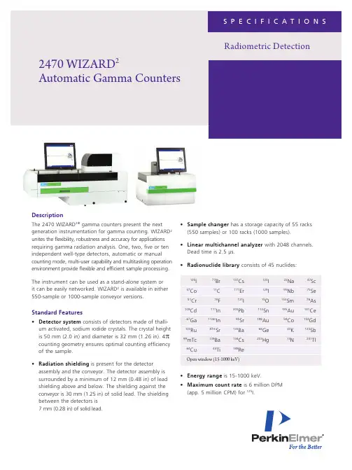
2470 WIZARD 2Automatic Gamma CountersDescriptionThe 2470 WIZARD 2® gamma counters present the next generation instrumentation for gamma counting. WIZARD 2 unites the flexibility, robustness and accuracy for applications requiring gamma radiation analysis. One, two, five or ten independent well-type detectors, automatic or manualcounting mode, multi-user capability and multitasking operationenvironment provide flexible and efficient sample processing.The instrument can be used as a stand-alone system or it can be easily networked. WIZARD 2 is available in either 550-sample or 1000-sample conveyor versions.Standard Features• Detector system consists of detectors made of thalli-um activated, sodium iodide crystals. The crystal height is 50 mm (2.0 in) and diameter is 32 mm (1.26 in). 4π counting geometry ensures optimal counting efficiency of the sample.• Radiation shielding is present for the detectorassembly and the conveyor. The detector assembly is surrounded by a minimum of 12 mm (0.48 in) of lead shielding above and below. The shielding against the conveyor is 30 mm (1.25 in) of solid lead. The shielding between the detectors is 7 mm (0.28 in) of solid lead.• Sample changer has a storage capacity of 55 racks (550 samples) or 100 racks (1000 samples).• Linear multichannel analyzer with 2048 channels. Dead time is 2.5 µs. • Radionuclide library consists of 45 nuclides: • Energy range is 15-1000 keV.• Maximum count rate is 6 million DPM (app. 5 million CPM) for 125I.Radiometric Detection2• Data analysis Wizard with WorkOut Plus, utilizesWindows ® 7 easy to use interface, has the flexibility to run the simplest assays to the most complex. WorkOut Plus’s ability to store preprogrammed assay templates, and transfer them to other Wizard2 counters saves time and effort in your busy laboratories.Quality Control and Regulations• Instrument Performance Assessment (IPA ™) allows follow up of variable instrument parameters for quality control purposes. IPA automatically monitors data, evalu-ates monitored data for quality assurance and provides out-of-control warnings for nine detector parameters including: – isotope main peak channel number – background CPM in counting window – relative detector efficiency – detector resolution – absolute detector efficiency – window coverage– detector stability probability – measured CPM in counting window – measured total CPM in whole spectrum• WIZARD 2 is manufactured according to ISO 9001 and ISO 13485 quality management systems.Optional WorkOut Plus Data Analysis• L AN connectivity and USB Makes networking and data transfer easy.• Results Viewer utility Access and export data from the WIZARD 2 database.Available ConfigurationsOptionsNew instrument orders:• 7005426 – WorkOut Plus Data Analysis software for WIZARD 2 Field upgrade only: • 7005429 – Upgrade kit Workout Plus• 7005430 - Upgrade Workout Plus ESRack and Sample Vial Specifications• Sample tube specifications are shown in the table below. In Automatic In ManualOperation Operation Maximum 13 mm (0.5 in) 15 mm (0.6 in) Diameter: (17 mm, 0.7 inwithout tray) Maximum cap diameter: 14 mm (0.6 in) 22 mm (0.9 in) Minimum diameter: No limit No limit Minimum height: No limit No limitMaximum 90 mm (3.5 in) 120 mm (4.7 in) height: (including cap) (including cap) Typical volume:~ 3 mL~ 3 mL• Tube shape Microcentrifuge tubes can be used without adapters. Eppendorf ® tubes can be measured at odd positions in sample racks.• Plastic sample racks can hold 10 samples/rack. Racks have barcodes for protocol and rack number identification. Supported barcode languages are code 128, interleaved 2/5, code 39 and codabar. Sample racks can have protocol barcodes 1-999. Sample racks are compatible with most centrifuges. Maximum centrifugation force 2500 x G.• Contamination guards are inherent in rack construction, protecting the detectors from contamination. Samples are separated from the detectors by liquid-tight, disposable sample holders.Operational Features• Built-in LCD touch screen for routine usage.• Built-in computer controlling the system is an industry standard computer with Microsoft ® Windows ® 7 operating system. The computer contains a USB connection for a memory stick, an external hard drive, a printer and an Ethernet connection for networking. • Alphanumeric keyboard and mouse for advanced usage on a pullout shelf.• Live spectrum display of counts, CPM or CPS values can be displayed on the screen. Counting spectrum can be displayed or plotted on the printer.• MultiSTAT interrupt counting enables a series of stat samples to be processed in manual mode while the assay in process is not affected. This allows the user to analyze urgent samples in the middle of long run.• Automatic normalization is carried out using a normal-ization cassette for each defined nuclide. • Datalogger enables all assay results to be automatically stored in a text file. Format is compatible with Microsoft ® Excel ®.For a complete listing of our global offices, visit /ContactUsCopyright ©2011-2018, PerkinElmer, Inc. All rights reserved. PerkinElmer ® is a registered trademark of PerkinElmer, Inc. All other trademarks are the property of their respective owners.009675B_01 PKIPerkinElmer, Inc. 940 Winter StreetWaltham, MA 02451 USA P: (800) 762-4000 or (+1) 203-925-4602Typical Performance DataAll background values are typical values at PerkinElmer's facility in Singapore. Background may vary due to local conditions.Background:125I 12 CPM 129I6 CPM 57Co90 CPM15-1000 keV 452 CPM Efficiency:125I 78%129I 58%51Cr 3%137Cs 26%58Co 3.5%Efficiency = CPM/DPM x 100%, window 15 keV–1000 keV Energy Resolution:125I < 30%129I< 30%51Cr < 14%137Cs< 12%58Co< 8%Spilldown :57Co into 125I < 3% (uncorrected) preset regions< 1% (corrected)Detector to detector crosstalk:125I Negligible57Co Negligible 51Cr < 0.5%137Cs < 4%58Co< 5%Conveyor to detector crosstalk:125I Negligible57Co Negligible 51Cr Negligible 137Cs< 0.12%58Co< 0.2%Physical DataDimensions:Height: 550/1000-sample model: 729 mm (28.7 in)Width: 550-sample model: 650 mm (25.6 in) 1000-sample model: 1190 mm (46.9 in)Depth: 550-sample model: 770 mm (30.3 in) 1000-sample model: 650 mm (25.6 in)Weight: 150 – 165 kg (330 – 365 lb)depending on the model Transport weight: 168 – 180 kg (370 – 400 lb)depending on the model Electrical 100 – 240 V at 50 – 60 Hz, requirements: 150 VA maximum Environmental Temperature range requirements:from +15 °C to +35 °CMaximum humidity 85%Electrical Safety RequirementsThe design of the instrument is based on the following electrical safety requirements:EN 61010-1 Safety requirements for electrical equipment for measurement, control and laboratory use EN 61326-1 Electrical equipment for measurement, control and laboratory use – EMC requirements EN 61010-2-101 Safety requirements for electricalequipment for measurement, control and laboratory use。


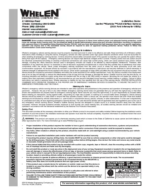
©2019 Whelen Engineering Company Inc.Form No.14C96 (102819)A u t o m o t i v e : S i r e n s /S w i t c h e sFor warranty information regarding this product, visit /warrantyDANGER! Sirens produce extremely loud emergency warning tones! Exposure to these tones without proper and adequate hearing protection, could cause ear damage and/or hearing loss! The Occupational Safety & Health Administration () provides information necessary to determine safe exposure times in Occupational Noise Exposure Section 1910.95. Until you have determined the safe exposure times for your specific application,operators and anyone else in the immediate vicinity should be required to wear an approved hearing protection device. Failure to follow this recommendation could cause hearing loss!•Proper installation of this product requires the installer to have a good understanding of automotive electronics, systems and procedures.•Whelen Engineering requires the use of waterproof butt splices and/or connectors if that connector could be exposed to moisture.•Any holes, either created or utilized by this product, should be made both air- and watertight using a sealant recommended by your vehicle manufacturer.•Failure to use specified installation parts and/or hardware will void the product warranty.•If mounting this product requires drilling holes, the installer MUST be sure that no vehicle components or other vital parts could be damaged by the drilling process. Check both sides of the mounting surface before drilling begins. Also de-burr the holes and remove any metal shards or remnants. Install grommets into all wire passage holes.•If this manual states that this product may be mounted with suction cups, magnets, tape or Velcro®, clean the mounting surface with a 50/50 mix of isopropyl alcohol and water and dry thoroughly.•Do not install this product or route any wires in the deployment area of your air bag. Equipment mounted or located in the air bag deployment area will damage or reduce the effectiveness of the air bag, or become a projectile that could cause serious personal injury or death. Refer to your vehicle owner’s manual for the air bag deployment area. The User/Installer assumes full responsibility to determine proper mounting location, based on providing ultimate safety to all passengers inside the vehicle.•For this product to operate at optimum efficiency, a good electrical connection to chassis ground must be made. The recommended procedure requires the product ground wire to be connected directly to the NEGATIVE (-) battery post (this does not include products that use cigar power cords).•If this product uses a remote device for activation or control, make sure that this device is located in an area that allows both the vehicle and the device to be operated safely in any driving condition.•It is recommended that these instructions be stored in a safe place and referred to when performing maintenance and/or reinstallation of this product.•FAILURE TO FOLLOW THESE SAFETY PRECAUTIONS AND INSTRUCTIONS COULD RESULT IN DAMAGE TO THE PRODUCT OR VEHICLE AND/OR SERIOUS INJURY TO YOU AND YOUR PASSENGERS!CAUTIONLoud siren noise can cause hearing damage and/or loss.Refer to OSHA Section 1910.95prior to putting ANY siren into service!Wear Protection!ACTIVATION OF THIS SIREN MAY DAMAGE UNPROTECTED EARS!Warnings to InstallersWhelen’s emergency vehicle warning devices must be properly mounted and wired in order to be effective and safe. Read and follow all of Whelen’s written instructions when installing or using this device. Emergency vehicles are often operated under high speed stressful conditions which must be accounted for when installing all emergency warning devices. Controls should be placed within convenient reach of the operator so that they can operate the system without taking their eyes off the roadway. Emergency warning devices can require high electrical voltages and/or currents. Properly protect and use caution around live electrical connections.Grounding or shorting of electrical connections can cause high current arcing, which can cause personal injury and/or vehicle damage, including fire. Many electronic devices used in emergency vehicles can create or be affected by electromagnetic interference. Therefore, after installation of any electronic device it is necessary to test all electronic equipment simultaneously to insure that they operate free of interference from other components within the vehicle. Never power emergency warning equipment from the same circuit or share the same grounding circuit with radio communication equipment. All devices should be mounted in accordance with the manufacturer’s instructions and securely fastened to vehicle elements of sufficient strength to withstand the forces applied to the device. Driver and/or passenger air bags (SRS) will affect the way equipment should be mounted. This device should be mounted by permanent installation and within the zones specified by the vehicle manufacturer, if any. Any device mounted in the deployment area of an air bag will damage or reduce the effectiveness of the air bag and may damage or dislodge the device. Installer must be sure that this device, its mounting hardware and electrical supply wiring does not interfere with the air bag or the SRS wiring or sensors. Mounting the unit inside the vehicle by a method other than permanent installation is not recommended as unit may become dislodged during swerving; sudden braking or collision. Failure to follow instructions can result in personal injury. Whelen assumes no liability for any loss resulting from the use of this warning device. PROPER INSTALLATION COMBINED WITH OPERATOR TRAINING IN THE PROPER USE OF EMERGENCY WARNING DEVICES IS ESSENTIAL TO INSURE THE SAFETY OF EMERGENCY PERSONNEL AND THE PUBLIC.Warnings to UsersWhelen’s emergency vehicle warning devices are intended to alert other operators and pedestrians to the presence and operation of emergency vehicles and personnel. However, the use of this or any other Whelen emergency warning device does not guarantee that you will have the right-of-way or that other drivers and pedestrians will properly heed an emergency warning signal. Never assume you have the right-of-way. It is your responsibility to proceed safely before entering an intersection, driving against traffic, responding at a high rate of speed, or walking on or around traffic lanes. Emergency vehicle warning devices should be tested on a daily basis to ensure that they operate properly. When in actual use, the operator must ensure that both visual and audible warnings are not blocked by vehicle components (i.e.: open trunks or compartment doors), people, vehicles, or other obstructions. It is the user’s responsibility to understand and obey all laws regarding emergency warning devices. The user should be familiar with all applicable laws and regulations prior to the use of any emergency vehicle warning device. Whelen’s audible warning devices are designed to project sound in a forward direction away from the vehicle occupants. However, because sustained periodic exposure to loud sounds can cause hearing loss, all audible warning devices should be installed and operated in accordance with the standards established by the National Fire Protection Association.Safety FirstThis document provides all the necessary information to allow your Whelen product to be properly and safely installed. Before beginning the installation and/or operation of your new product, the installation technician and operator must read this manual completely. Important information is contained herein that could prevent serious injury or damage.WARNING: This product can expose you to chemicals including Lead which is known to the State of California to cause cancer and birth defects or other reproductive harm. For more information go to .Installation Guide:Cantrol™/Carbide™ CAN Interface Harness(2020 Ford Interceptor Utility)51 Winthrop RoadChester, Connecticut 06412-0684Phone: (860) 526-9504Internet: Sales e-mail: autosale@Customer Service e-mail: custserv@®ENGINEERING COMPANY INC.2.Locate the CAN port Interface Cable (included). This cable allows the Cantrol™ or Carbide™ system to communicate with your vehicle’s CAN network.The interface cable is comprised of the following connectors:•One 6-position YES 2.8 Series Connector male•One 3 position connectorThe Canport communication board consists of the following components:•USB Port - This port is used exclusively for programming the CANport Communication Board. All other system programming uses the standard USB port found on the CanTrol / Carbide module.•USB Status LED (Blue) - This LED,located adjacent to the 8-positionconnector, indicates one of threepotential USB states:Off - No connection detected.Slow Flash - For factory purposesonly.Fast Flash - Connection detected,not ready.Steady - Connection detected,ready for use.•8-position Connector - Thisconnector is used to connect theCANport Interface Cable to theCanTrol / Carbide module.connector into the CAN2 port onand diagnostic data may now beconnector installed earlier in thissystem to interact with thelaptop computer. Thisand is only needed during theColorBLUGRY8 Position ConnectorPin DescriptionColor1. . . . . . . . Signal - High (CAN 1).........................BLU2. . . . . . . . Signal - Shield (CAN 1)...................Shield3. . . . . . . . Signal - Low (CAN 1)........................GRY4. . . . . . . . Speed Output......................................VIO5. . . . . . . . No Connection6. . . . . . . . No Connection7. . . . . . . . No Connection8. . . . . . . . Speed Ground....................................BLK。
高斯计,是测量物体于空间上一个点的静态或动态(交流)磁感应强度, 由霍尔传感器(精度更高可选择磁通门传感器).经过物体磁力线穿过产生电流电压,主设备上面显示磁感应强度.简介高斯计是根据霍尔效应制成的测量磁感应强度的仪器,它由霍尔探头和测量仪表构成。
霍尔探头在磁场中因霍尔效应而产生霍尔电压,测出霍尔电压后根据霍尔电压公式和已知的霍尔系数可确定磁感应强度的大小。
高斯计的读数以高斯或千高斯为单位。
高斯计是用于测量和显示单位面积平均磁通密度或磁感应强度的精密仪器。
原理目前的高斯计几乎都是基于霍尔效应原理进行磁场测量的,采用霍尔传感器作为磁感应元件。
用户可能会发现这样的问题,即使在同一个点上,使用不同型号的探头会产生不同的测量结果。
这并非是测量的错误,而是由于霍尔传感器的尺寸不同以及装配的位置误差产生的结果。
根据不同的需要,正确地选择高斯计和相应的霍尔探头尤为重要。
高斯计的测试材料-硬磁材料解析高斯计一般是用来测试一些磁性材料的磁通量的仪器。
为了更好的选择合适的产品,我们有必要了解一下哪些是硬磁材料,哪些是软磁材料?高斯计的测试对象一:硬磁材料永磁功能材料常称永磁材料,又称硬磁材料,而软磁功能材料常称软磁材料。
这里的硬和软并不是指力学性能上的硬和软,而是指磁学性能上的硬和软。
1.磁性硬是指磁性材料经过外加磁场磁化以后能长期保留其强磁性(简称磁性),其特征是矫顽力(矫顽磁场)高。
矫顽力是磁性材料经过磁化以后再经过退磁使具剩余磁性(剩余磁通密度或剩余磁化强度)降低到零的磁场强度。
2.软磁材料则是加磁场既容易磁化,又容易退磁,即矫顽力很低的磁性材料。
退磁是指在加磁场(称为磁化场)使磁性材料磁化以后,再加同磁化场方向相反的磁场使其磁性降低的磁场。
目前,永磁材料是发现和使用都最早的一类磁性材料。
我国最早发明的指南器(称为司南)便是利用天然永磁材料磁铁矿制成的。
现在的永磁材料不但种类很多,而且用途也十分广泛。
高斯计被测对象-常用的永磁材料主要具有4种磁特性:(1)高的最大磁能积。
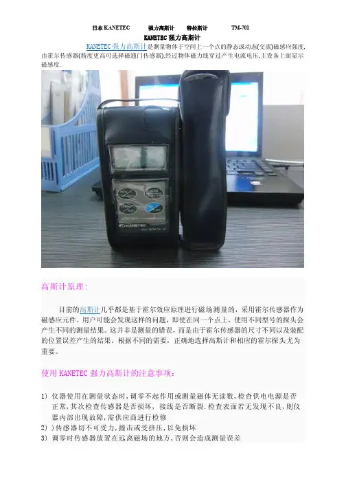
KANETEC强力高斯计KANETEC强力高斯计是测量物体于空间上一个点的静态或动态(交流)磁感应强度, 由霍尔传感器(精度更高可选择磁通门传感器).经过物体磁力线穿过产生电流电压,主设备上面显示磁感度.高斯计原理:目前的高斯计几乎都是基于霍尔效应原理进行磁场测量的,采用霍尔传感器作为磁感应元件。
用户可能会发现这样的问题,即使在同一个点上,使用不同型号的探头会产生不同的测量结果。
这并非是测量的错误,而是由于霍尔传感器的尺寸不同以及装配的位置误差产生的结果。
根据不同的需要,正确地选择高斯计和相应的霍尔探头尤为重要。
使用KANETEC强力高斯计的注意事项:1)仪器使用在测量状态时,调零不起作用或测量磁体无读数,检查供电电源是否正常,其次检查传感器是否损坏, 接线是否断裂.检查表面若无发现不良,则仪器内部出现故障,需供应商进行检修2))传感器切不可受力,撞击或受挤压,以免损坏3)调零时传感器放置在远离磁场的地方,否则会造成测量误差4)仪器应避免在不符合使用环境条件下使用5)在测量时发现测量数值确实有偏差,可旋开传感器后端的手柄将其中的电位器进行微调以达到正确的测量结果。
日本KANETEC强力高斯计TM-701高斯计应用:测量加工工件上残留的磁通量。
磁性应用产品的磁通量测量。
电机的磁通量测量。
TM-701高斯计测量磁性材料的性能。
日本KANETEC强力高斯计TM-701特点:测量范围大:0-3000mT(0-30000G)(DC)电池寿命延长30%探头的硬度增强可配可充电电池使用TM-701高斯计外部输出端口接上选配连接线(TM-601DTC),可将数显数据(模拟数据)传入电脑可测量交流和直流磁场的磁通量高精度测量模式可保证更精确的测量可切换显示的单位:mT或GTM-701高斯计采用触摸键,具有很好的防尘作用自动关机功能,可节省电源旧探头磨损,更换新探头后,无需进行校准TM701日本强力KANETEC手持式高斯计TM-701标配探头TM-701PRB应用: 测量加工工件上残留的磁通量。
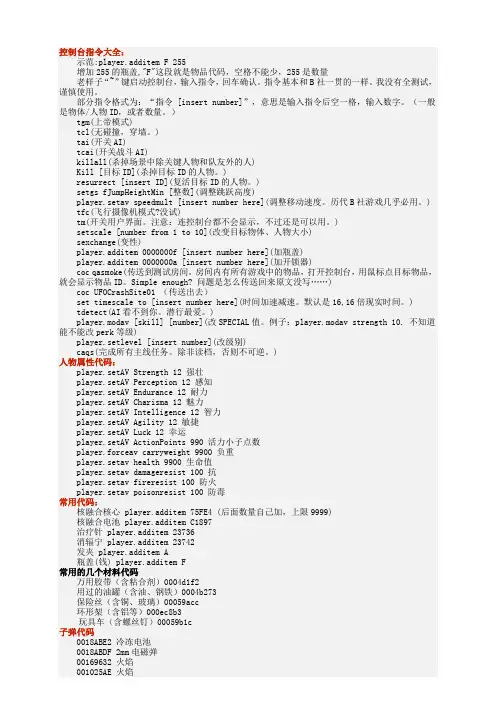
控制台指令大全:示范:player.additem F 255增加255的瓶盖,"F"这段就是物品代码,空格不能少,255是数量老样子“~”键启动控制台,输入指令,回车确认。
指令基本和B社一贯的一样。
我没有全测试,谨慎使用。
部分指令格式为:“指令 [insert number]”,意思是输入指令后空一格,输入数字。
(一般是物体/人物ID,或者数量。
)tgm(上帝模式)tcl(无碰撞,穿墙。
)tai(开关AI)tcai(开关战斗AI)killall(杀掉场景中除关键人物和队友外的人)Kill [目标ID](杀掉目标ID的人物。
)resurrect [insert ID](复活目标ID的人物。
)setgs fJumpHeightMin [整数](调整跳跃高度)player.setav speedmult [insert number here](调整移动速度。
历代B社游戏几乎必用。
) tfc(飞行摄像机模式?没试)tm(开关用户界面。
注意:连控制台都不会显示,不过还是可以用。
)setscale [number from 1 to 10](改变目标物体、人物大小)sexchange(变性)player.additem 0000000f [insert number here](加瓶盖)player.additem 0000000a [insert number here](加开锁器)coc qasmoke(传送到测试房间。
房间内有所有游戏中的物品,打开控制台,用鼠标点目标物品,就会显示物品ID。
Simple enough? 问题是怎么传送回来原文没写……)coc UFOCrashSite01 (传送出去)set timescale to [insert number here](时间加速减速。
默认是16,16倍现实时间。
) tdetect(AI看不到你。
潜行最爱。
)player.modav [skill] [number](改SPECIAL值。
直读式电子比重计DH-300操作说明书请仔细阅读本说明书,以便正确使用。
请妥善保管本说明书,以备不时之需。
东莞市宏拓仪器有限公司-DahoMeter达宏美拓-服务热线:400 830 0646首次使用说明由于机器首次使用、运输、突然断电、重量损失等原因导致零点改变所引起按键无反应、显示OL 、不能正常显示0.00时,请按如下步骤操作,可排除上述现象。
在确定测量台和水中吊篮上的物品已经清空及水中吊篮与水槽没有接触的情况下: 1.关机。
2.长按【C 】键,再开机直至屏幕显示【CAL 】时方可放手。
3. 按【B 】键一次,显示数字【2】。
(如按【B 】键无反应,请重新尝试上述三个步骤,直至屏幕显示对应数字【2】为止)4. 按【A 】键一次 ,显示数字【1】。
5. 按【ZERO 】键一次,显示数字【3】。
6. 再按【ZERO 】键一次,显示数字【3】。
7. 按【C 】键一次,显示数字【5】。
8. 按【ENTER 】键一次,显示【CAL 】。
(若未显示【CAL 】请重复4-7四个步骤)9. 按【C】键一次,显示多位变化的数字。
10. 按【C】键一次,显示一位或者二位会跳动的数字。
11. 在测量台中央位置放上100g砝码。
12. 按【ENTER】键一次,显示【100】。
13. 再按【ENTER】键一次,显示【100.00】。
14. 取下砝码后,重新开机,即可解决上述现象,做正常校正后即可使用。
※注意:在关机前,请将测量台及吊篮中的物品取出。
(如测试样品、网球、抗浮架、玻璃杯等)。
DahoMeter达宏美拓-服务热线:400 830 0646目录1.概述 (5)1.1原理 (5)1.2用途 (5)2.规格参数 (5)3.仪器介绍 (6)3.1 仪器及配件清单说明 (6)3.2按键功能介绍 (7)3.3显示屏介绍 (7)4.安装 (8)4.1安装环境 (8)4.2防风罩安装 (8)4.3仪器安装 (8)5.校正方法 (9)6.其它设定 (9)6.1温度补偿 (9)6.2其它溶液比重值设定 (10)6.3水温密度对照表 (11)7.测试方法 (11)7.1样品重量参考 (11)7.2 固体测量(密度>1) (12)7.3 浮体测量(比重<1) (13)7.4 颗粒测量 (14)7.5测试结果的选择 (15)8.故障排除方法 (15)9.注意事项及保养 (16)9.1 使用前注意事项 (16)9.2 使用时注意事项 (16)9.3 特别注意事项 (16)1.概述1.1原理直读电子比重计DH-300是根据ASTM D297-93、D792-00、D618、D891等标准,采用阿基米德水中置换法原理与现代微电子技术相结合,以实际温度下水的密度为基础,经过两次重量测量分别得出待测样品的质量与体积,从而通过微电脑直接计算出样品之比重。
控制台指令大全:(注:实际代码是我找的10倍左右这些就够用了,除了没有技能代码以外全是实用的)示范:player.additem F 255增加255的瓶盖,"F"这段就是物品代码,空格不能少,255是数量老样子“~”键启动控制台,输入指令,回车确认。
指令基本和B社一贯的一样。
我没有全测试,谨慎使用。
部分指令格式为:“指令 [insert number]”,意思是输入指令后空一格,输入数字。
(一般是物体/人物ID,或者数量。
)tgm(上帝模式)tcl(无碰撞,穿墙。
)tai(开关AI)tcai(开关战斗AI)killall(杀掉场景中除关键人物和队友外的人)Kill [目标ID](杀掉目标ID的人物。
)resurrect [insert ID](复活目标ID的人物。
)setgs fJumpHeightMin [整数](调整跳跃高度)player.setav speedmult [insert number here](调整移动速度。
历代B社游戏几乎必用。
) tfc(飞行摄像机模式?没试)tm(开关用户界面。
注意:连控制台都不会显示,不过还是可以用。
)setscale [number from 1 to 10](改变目标物体、人物大小)sexchange(变性)player.additem 0000000f [insert number here](加瓶盖)player.additem 0000000a [insert number here](加开锁器)coc qasmoke(传送到测试房间。
房间内有所有游戏中的物品,打开控制台,用鼠标点目标物品,就会显示物品ID。
Simple enough? 问题是怎么传送回来原文没写……)coc UFOCrashSite01 (传送出去)set timescale to [insert number here](时间加速减速。
默认是16,16倍现实时间。
战员井型伽马计数器法
你好,我不知道“战员井型伽马计数器法”的具体含义和内容。
但我可以为你提供关于“伽马井型计数器”的相关介绍,希望对你有所帮助。
伽马井型计数器是一种用于RIA(放射免疫分析)和科学研究的高性能仪器。
它具有8种规格,可满足不同需求,如1、2、3、4、5、6、8或10个探测器。
该计数器使用井型NaI (TL)探测器,可实现高效检测(对于I125,效率超过80%),并通过4096通道分析器提供准确的分析结果和能谱绘制。
此外,该计数器可连接到PC、Mac、Unix/Linux或LIS,并且具有E-lead™技术,能够消除高能量串扰(如Cr51、Fe59等)。
如果你需要了解更多关于“伽马井型计数器”的信息,可以继续向我提问。
日本强力TM701高斯计
强力高斯计TM701说明书
第一次使用时,安装4节(R-6)干电池.在主机背部,按下(OPEN)打开电池箱盖,放入电池,并
保证电池正负极方向正确. 强力高斯计TM701
注意
一定使用规定的(R-6)干电池,其它非制空权的电池组可导致使用失效.
1,连接探头,确保高斯计开关在”OFF”
2,在确保顶部连接器及探头针部无外界物质例如灰尘后,轻轻地将探头插到底,并保证探头
和连接器的一致线性. 维修高斯计,维修TM701,维修日本强力高斯计,维修高斯计701强力高斯计TM701
注意:如果外界物质如灰尘粘在探头或连接器而导致非一致线形,也会使使用失效.
3,高斯计电源,使用高斯计时,压下ON/OFF开关
注意;在操作开关时,应轻轻压下它,如操作粗鲁,使用失效.
(在电源打开时改变显示) 强力高斯计TM701
在电源打开后,立即显示初始指示,在显示时,除了ON/OFF开关,其他按钮的操作均不被接受. 维修高斯计,维修TM701,维修日本强力高斯计,维修高斯计701
4,选择测量状态
电源打开后,机器总是在DCXI的测量状态下开始.当压下AC/DC开关,测量状态发生如下变化.根据测量目的选择合适的状态.只有在REAL状态下才能进行状态转换.
5,调整零点强力高斯计TM701
在开始测量之前,将探头放在没有磁场存在的空间,并确保在REAL状态下,然后压下
ZERO/RESET开关.显示器显示”0”
5测量维修高斯计,维修TM701,维修强力高斯计TM701日本强力高斯计,维修高斯计701 移开探头尖部的盖进行测量,读取极性和测量值.
测量最大值:为测量最大值,建议HOLD状态.压下REAL/HOLD开关,选择HOLD状态,HOLD会显示在显示器上,显示后,只有按下XERO/RESET开关才能开始测量.当两次压下REAL/HOLD开关,高斯计强力高斯计TM701转换到REAL状态,HOLD标记消失.
AC磁场测量
在AC磁场测量时,这种设备的支持频率在50HZ-60HZ.在其它频率下,磁场密度会显示,但精
度不能保证. 维修高斯计,维修TM701,维修日本强力高斯计,维修高斯计701 在DC磁场下也是一样,由于磁流量的快速变化或磁极的改变,数值也会在AC磁场测量状态显示.如果这样,在REAL状态下保持探头固定一会强力高斯计TM701,检查显示值.
如显示值是零,表明没有AC磁场的存在.
测量期间的显示
在DC标准分度测量状态DCXI下REAL显示的例子.(N极1500MT)
在DC标准分度测量状态(DCXI)下HOLD显示的例子.(N极1500MT)
在DC高分度过测量状态(DCX10)下显示的例子(N极50.01MT)
在AC标准分度测量状态(ACXI)下显示的例子.(AC10.0MT)
在每一种状态下测量超出范围的显示.
在REAL状态下,如重新设置显示,要强力高斯计TM701从磁场中移开.在HOLD状态下,重新设置时按下ZERO/RESET开关,测量即可进行.
7测量终止. 维修高斯计,维修TM701,维修日本强力高斯计,维修高斯计701
在使用后,盖好探头盖子.
关闭电源.
在使用后,确保按下ON/OFF开关以强力高斯计TM701关闭电源,如电源由于某些原因未关闭,该表有自动关闭电源的功能,电源会在最后一次操作后15分钟自动关维修高斯计,维修TM701,维修日本强力高斯计,维修高斯计701TM-701高斯计(特斯拉计)
特斯拉计是结合KANETEC公司多年的磁性产品的经验和成果研制出的,一种实用的、手拿式的数显高斯计。
此款高斯计,人性化设计,操作简单、方便。
TM-701高斯计
高斯计配有输出接口,可进行数字或模拟输出。
与之前的产品相比,TM-701的探头更小,可在较小的区域测量。
日本KANETEC强力高斯计TM-701高斯计
TM-701高斯计 [应用]
·测量加工工件上残留的磁通量。
·磁性应用产品的磁通量测量。
·电机的磁通量测量。
TM-701高斯计
·测量磁性材料的性能。
TM-701高斯计 [特点]
§测量范围大:0-3000mT(0-30000G)(DC)
§电池寿命延长30%
§探头的硬度增强
§可配可充电电池使用TM-701高斯计
§外部输出端口接上选配连接线(TM-601DTC),可将数显数据(模拟数据)传入电脑
§可测量交流和直流磁场的磁通量
§高精度测量模式可保证更精确的测量
§可切换显示的单位:mT或GTM-701高斯计
§采用触摸键,具有很好的防尘作用
§自动关机功能,可节省电源
§旧探头磨损,更换新探头后,无需进行校准
高斯计
强力高斯计北京朗科精密仪器
KANETEC 备受好评中的 TM 系列,在各种各样的测量,检查时能对应的新机能外部输出机能附着新型 TESLA METER MODEL TM-701
一.产品介绍
二.特点
1. 是电子式。
2. 可选购传输线(TM-601DTC)连接到个人计算机,透过软件来仿真数据。
*(注 1)
3. 重量仅仅 250g 小型轻量类型。
4. 超大的液晶显示。
5. 有直流磁通密度(DC)和交流磁通密度(AC)的测量。
有(50/60Hz)
6. 0∼3000Mt((0 ∼30000G)的测量有效范围。
7. 最小读值分辨率 0.01mT=0.1G。
8. mT (默认值)、G 的功能切换。
9. 自动关闭电源(约 15 分钟),能减少电池的消耗。
10. 探针交换
后即可进行量测,无需在校对。
三.用途例子
1. 机械加工工作的残留磁的量测及应用产品的磁通密度测量。
2. 电动机的磁通密度测量。
3. 磁性材料的特性测量。
4. 不锈钢产品的机械状态检查。
5. 磁铁的磁通密度的测量。
6. 各种钢材的自然带子磁检查。
四.注意事项
1. 使用前请〝小心〞出测头以防折断,测量时测头只需轻轻接触
即可,不要大力下压。
2. 量测完毕后,请立即将测头收入保护套内,以防意外折断。
3. 若电力不足时,屏幕则会出现电池图样,此时请更换电池。
五.按键功能
1. REAL/HOLD
选择 PEAK 值或一般使用(REAL 为一般使用,HOLD 为 PEAK 值)。
2. ZERO/RESET 强迫归零键,因正常使用下,测头会因长期磁
性体而产生无法使用 RESET 归零。
3. AC/DC 切换交流与直
流之切换。
4. ON/OFF
电源开关键。
六.测量方法
1. 按 ON/OFF 开关约 2 秒,即呈现开机状态,此时单位显示为
mT。
2. 量测时屏幕自动显示 N/S 极。
3. 按 REAL/HOLD 屏幕上显示 HOLD 为 PEAK 值,若无即在一般使用状态。
4. 若要更换单为(mT G),则在关机状态下,把电池盖打开,
电池取出,即可看见 IC 板上有块突出物,往右侧移动,此时单位更换成 G(Gauss),默认值为 mT。