高斯计LZ-640 使用手册 英文 版
- 格式:pdf
- 大小:384.04 KB
- 文档页数:13


Features•High Performance, Low Power AVR® 8-Bit Microcontroller •Advanced RISC Architecture–135 Powerful Instructions – Most Single Clock Cycle Execution –32 x 8 General Purpose Working Registers–Fully Static Operation–Up to 16 MIPS Throughput at 16 MHz–On-Chip 2-cycle Multiplier•Non-volatile Program and Data Memories–64K/128K/256K Bytes of In-System Self-Programmable FlashEndurance: 10,000 Write/Erase Cycles–Optional Boot Code Section with Independent Lock BitsIn-System Programming by On-chip Boot ProgramTrue Read-While-Write Operation–4K Bytes EEPROMEndurance: 100,000 Write/Erase Cycles–8K Bytes Internal SRAM–Up to 64K Bytes Optional External Memory Space–Programming Lock for Software Security•JTAG (IEEE std. 1149.1 compliant) Interface–Boundary-scan Capabilities According to the JTAG Standard–Extensive On-chip Debug Support–Programming of Flash, EEPROM, Fuses, and Lock Bits through the JTAG Interface •Peripheral Features–Two 8-bit Timer/Counters with Separate Prescaler and Compare Mode–Four 16-bit Timer/Counter with Separate Prescaler, Compare- and Capture Mode –Real Time Counter with Separate Oscillator–Four 8-bit PWM Channels–Six/Twelve PWM Channels with Programmable Resolution from 2 to 16 Bits(ATmega1281/2561, ATmega640/1280/2560)–Output Compare Modulator–8/16-channel, 10-bit ADC (ATmega1281/2561, ATmega640/1280/2560)–Two/Four Programmable Serial USART (ATmega1281/2561,ATmega640/1280/2560)–Master/Slave SPI Serial Interface–Byte Oriented 2-wire Serial Interface–Programmable Watchdog Timer with Separate On-chip Oscillator–On-chip Analog Comparator–Interrupt and Wake-up on Pin Change•Special Microcontroller Features–Power-on Reset and Programmable Brown-out Detection–Internal Calibrated Oscillator–External and Internal Interrupt Sources–Six Sleep Modes: Idle, ADC Noise Reduction, Power-save, Power-down, Standby, and Extended Standby•I/O and Packages–54/86 Programmable I/O Lines (ATmega1281/2561, ATmega640/1280/2560)–64-pad QFN/MLF, 64-lead TQFP (ATmega1281/2561)–100-lead TQFP, 100-ball CBGA (ATmega640/1280/2560)–RoHS/Fully Green•Temperature Range:–-40°C to 85°C Industrial•Ultra-Low Power Consumption–Active Mode: 1 MHz, 1.8V: 510 µA–Power-down Mode: 0.1 µA at 1.8V•Speed Grade (see “Maximum speed vs. VCC” on page 377):–ATmega640V/ATmega1280V/ATmega1281V:0 - 4 MHz @ 1.8 - 5.5V, 0 - 8 MHz @ 2.7 - 5.5V–ATmega2560V/ATmega2561V:0 - 2 MHz @ 1.8 - 5.5V, 0 - 8 MHz @ 2.7 - 5.5V–ATmega640/ATmega1280/ATmega1281:0 - 8 MHz @ 2.7 - 5.5V, 0 - 16 MHz @ 4.5 - 5.5V–ATmega2560/ATmega2561:0 - 16 MHz @ 4.5 - 5.5V 8-bit Microcontroller64K/128K/256K Bytes In-System ProgrammableATmega640/V ATmega1280/V ATmega1281/V2ATmega640/1280/1281/2560/25612549KS–AVR–01/07Pin ConfigurationsFigure 1. TQFP-pinout ATmega640/1280/25603ATmega640/1280/1281/2560/25612549KS–AVR–01/07Figure 2. CBGA-pinout ATmega640/1280/2560Table 1. CBGA-pinout ATmega640/1280/2560.12345678910A G N D AREF PF0PF2PF5PK0PK3PK6G N D VCC B AVCC PG5PF1PF3PF6PK1PK4PK7PA0PA2C PE2PE0PE1PF4PF7PK2PK5PJ7PA1PA3D PE3PE4PE5PE6PH2PA4PA5PA6PA7PG2E PE7PH0PH1PH3PH5PJ6PJ5PJ4PJ3PJ2F VCC PH4PH6PB0PL4PD1PJ1PJ0PC7G N D G G N D PB1PB2PB5PL2PD0PD5PC5PC6VCC H PB3PB4RESET PL1PL3PL7PD4PC4PC3PC2J PH7PG3PB6PL0XT AL2PL6PD3PC1PC0PG1KPB7PG4VCCG N DXT AL1PL5PD2PD6PD7PG04ATmega640/1280/1281/2560/25612549KS–AVR–01/07Figure 3. Pinout ATmega1281/2561N ote:The large center pad underneath the QF N /MLF package is made of metal and internally connected to G N D. It should be soldered or glued to the board to ensure good mechani-cal stability. If the center pad is left unconnected, the package might loosen from the board.DisclaimerTypical values contained in this datasheet are based on simulations and characteriza-tion of other AVR microcontrollers manufactured on the same process technology. Min.and Max values will be available after the device is characterized.5ATmega640/1280/1281/2560/25612549KS–AVR–01/07OverviewThe ATmega640/1280/1281/2560/2561 is a low-power CMOS 8-bit microcontroller based on the AVR enhanced RISC architecture. By executing powerful instructions in a single clock cycle, the ATmega640/1280/1281/2560/2561 achieves throughputs approaching 1 MIPS per MHz allowing the system designer to optimize power consumption versus processing speed.Block DiagramFigure 4. Block Diagram6ATmega640/1280/1281/2560/25612549KS–AVR–01/07The AVR core combines a rich instruction set with 32 general purpose working registers.All the 32 registers are directly connected to the Arithmetic Logic Unit (ALU), allowing two independent registers to be accessed in one single instruction executed in one clock cycle. The resulting architecture is more code efficient while achieving throughputs up to ten times faster than conventional CISC microcontrollers.The ATmega640/1280/1281/2560/2561 provides the following features: 64K/128K/256K bytes of In-System Programmable Flash with Read-W hile-W rite capabilities, 4K bytes EEPROM, 8K bytes SRAM, 54/86 general purpose I/O lines, 32 general purpose work-ing registers, Real Time Counter (RTC), six flexible Timer/Counters with compare modes and P W M, 4 USARTs, a byte oriented 2-wire Serial Interface, a 16-channel, 10-bit ADC with optional differential input stage with programmable gain, programmable W atchdog Timer with Internal Oscillator, an SPI serial port, IEEE std. 1149.1 compliant JTAG test interface, also used for accessing the On-chip Debug system and program-ming and six software selectable power saving modes. The Idle mode stops the CPU while allowing the SRAM, Timer/Counters, SPI port, and interrupt system to continue functioning. The Power-down mode saves the register contents but freezes the Oscilla-tor, disabling all other chip functions until the next interrupt or Hardware Reset. In Power-save mode, the asynchronous timer continues to run, allowing the user to main-tain a timer base while the rest of the device is sleeping. The ADC N oise Reduction mode stops the CPU and all I/O modules except Asynchronous Timer and ADC, to min-imize switching noise during ADC conversions. In Standby mode, the Crystal/Resonator Oscillator is running while the rest of the device is sleeping. This allows very fast start-up combined with low power consumption. In Extended Standby mode, both the main Oscillator and the Asynchronous Timer continue to run.The device is manufactured using Atmel’s high-density nonvolatile memory technology.The On-chip ISP Flash allows the program memory to be reprogrammed in-system through an SPI serial interface, by a conventional nonvolatile memory programmer, or by an On-chip Boot program running on the AVR core. The boot program can use any interface to download the application program in the application Flash memory. Soft-ware in the Boot Flash section will continue to run while the Application Flash section is updated, providing true Read-W hile-W rite operation. By combining an 8-bit RISC CPU with In-System Self-Programmable Flash on a monolithic chip, the Atmel ATmega640/1280/1281/2560/2561 is a powerful microcontroller that provides a highly flexible and cost effective solution to many embedded control applications.The ATmega640/1280/1281/2560/2561 AVR is supported with a full suite of program and system development tools including: C compilers, macro assemblers, program debugger/simulators, in-circuit emulators, and evaluation kits.7ATmega640/1280/1281/2560/25612549KS–AVR–01/07Comparison Between ATmega1281/2561 and ATmega640/1280/2560Each device in the ATmega640/1280/1281/2560/2561 family differs only in memory size and number of pins. Table 2 summarizes the different configurations for the six devices.Pin DescriptionsVCC Digital supply voltage.GNDGround.Port A (PA7..PA0)Port A is an 8-bit bi-directional I/O port with internal pull-up resistors (selected for each bit). The Port A output buffers have symmetrical drive characteristics with both high sink and source capability. As inputs, Port A pins that are externally pulled low will source current if the pull-up resistors are activated. The Port A pins are tri-stated when a reset condition becomes active, even if the clock is not running.P o r t A a l s o s e r v e s t h e f u n c t i o n s o f v a r i o u s s p e c i a l f e a t u r e s o f t h e ATmega640/1280/1281/2560/2561 as listed on page 91.Port B (PB7..PB0)Port B is an 8-bit bi-directional I/O port with internal pull-up resistors (selected for each bit). The Port B output buffers have symmetrical drive characteristics with both high sink and source capability. As inputs, Port B pins that are externally pulled low will source current if the pull-up resistors are activated. The Port B pins are tri-stated when a reset condition becomes active, even if the clock is not running.Port B has better driving capabilities than the other ports.P o r t B a l s o s e r v e s t h e f u n c t i o n s o f v a r i o u s s p e c i a l f e a t u r e s o f t h e ATmega640/1280/1281/2560/2561 as listed on page 92.Port C (PC7..PC0)Port C is an 8-bit bi-directional I/O port with internal pull-up resistors (selected for each bit). The Port C output buffers have symmetrical drive characteristics with both high sink and source capability. As inputs, Port C pins that are externally pulled low will source current if the pull-up resistors are activated. The Port C pins are tri-stated when a reset condition becomes active, even if the clock is not running.P o r t C a l s o s e r v e s t h e f u n c t i o n s o f s p e c i a l f e a t u r e s o f t h e ATmega640/1280/1281/2560/2561 as listed on page 95.Port D (PD7..PD0)Port D is an 8-bit bi-directional I/O port with internal pull-up resistors (selected for each bit). The Port D output buffers have symmetrical drive characteristics with both high sink and source capability. As inputs, Port D pins that are externally pulled low will sourceTable 2. Configuration SummaryDevice Flash EEPROM RAM GeneralPurpose I/O pins16 bits resolution PWM channelsSerial USARTsADC ChannelsA Tmega64064KB 4KB 8KB 8612416A Tmega1280128KB 4KB 8KB 8612416A Tmega1281128KB 4KB 8KB 54628A Tmega2560256KB 4KB 8KB 8612416A Tmega2561256KB4KB8KB546288ATmega640/1280/1281/2560/25612549KS–AVR–01/07current if the pull-up resistors are activated. The Port D pins are tri-stated when a reset condition becomes active, even if the clock is not running.P o r t D a l s o s e r v e s t h e f u n c t i o n s o f v a r i o u s s p e c i a l f e a t u r e s o f t h e ATmega640/1280/1281/2560/2561 as listed on page 97.Port E (PE7..PE0)Port E is an 8-bit bi-directional I/O port with internal pull-up resistors (selected for each bit). The Port E output buffers have symmetrical drive characteristics with both high sink and source capability. As inputs, Port E pins that are externally pulled low will source current if the pull-up resistors are activated. The Port E pins are tri-stated when a reset condition becomes active, even if the clock is not running.P o r t E a l s o s e r v e s t h e f u n c t i o n s o f v a r i o u s s p e c i a l f e a t u r e s o f t h e ATmega640/1280/1281/2560/2561 as listed on page 99.Port F (PF7..PF0)Port F serves as analog inputs to the A/D Converter.Port F also serves as an 8-bit bi-directional I/O port, if the A/D Converter is not used.Port pins can provide internal pull-up resistors (selected for each bit). The Port F output buffers have symmetrical drive characteristics with both high sink and source capability.As inputs, Port F pins that are externally pulled low will source current if the pull-up resistors are activated. The Port F pins are tri-stated when a reset condition becomes active, even if the clock is not running. If the JTAG interface is enabled, the pull-up resis-tors on pins PF7(TDI), PF5(TMS), and PF4(TCK) will be activated even if a reset occurs.Port F also serves the functions of the JTAG interface.Port G (PG5..PG0)Port G is a 6-bit I/O port with internal pull-up resistors (selected for each bit). The Port G output buffers have symmetrical drive characteristics with both high sink and source capability. As inputs, Port G pins that are externally pulled low will source current if the pull-up resistors are activated. The Port G pins are tri-stated when a reset condition becomes active, even if the clock is not running.P o r t G a l s o s e r v e s t h e f u n c t i o n s o f v a r i o u s s p e c i a l f e a t u r e s o f t h e ATmega640/1280/1281/2560/2561 as listed on page 105.Port H (PH7..PH0)Port H is a 8-bit bi-directional I/O port with internal pull-up resistors (selected for each bit). The Port H output buffers have symmetrical drive characteristics with both high sink and source capability. As inputs, Port H pins that are externally pulled low will source current if the pull-up resistors are activated. The Port H pins are tri-stated when a reset condition becomes active, even if the clock is not running.P o r t H a l s o s e r v e s t h e f u n c t i o n s o f v a r i o u s s p e c i a l f e a t u r e s o f t h e ATmega640/1280/2560 as listed on page 107.Port J (PJ7..PJ0)Port J is a 8-bit bi-directional I/O port with internal pull-up resistors (selected for each bit). The Port J output buffers have symmetrical drive characteristics with both high sink and source capability. As inputs, Port J pins that are externally pulled low will source current if the pull-up resistors are activated. The Port J pins are tri-stated when a reset condition becomes active, even if the clock is not running.P o r t J a l s o s e r v e s t h e f u n c t i o n s o f v a r i o u s s p e c i a l f e a t u r e s o f t h e ATmega640/1280/2560 as listed on page 109.Port K (PK7..PK0)Port K serves as analog inputs to the A/D Converter.9ATmega640/1280/1281/2560/25612549KS–AVR–01/07Port K is a 8-bit bi-directional I/O port with internal pull-up resistors (selected for each bit). The Port K output buffers have symmetrical drive characteristics with both high sink and source capability. As inputs, Port K pins that are externally pulled low will source current if the pull-up resistors are activated. The Port K pins are tri-stated when a reset condition becomes active, even if the clock is not running.P o r t K a l s o s e r v e s t h e f u n c t i o n s o f v a r i o u s s p e c i a l f e a t u r e s o f t h e ATmega640/1280/2560 as listed on page 111.Port L (PL7..PL0)Port L is a 8-bit bi-directional I/O port with internal pull-up resistors (selected for each bit). The Port L output buffers have symmetrical drive characteristics with both high sink and source capability. As inputs, Port L pins that are externally pulled low will source current if the pull-up resistors are activated. The Port L pins are tri-stated when a reset condition becomes active, even if the clock is not running.P o r t L a l s o s e r v e s t h e f u n c t i o n s o f v a r i o u s s p e c i a l f e a t u r e s o f t h e ATmega640/1280/2560 as listed on page 113.Reset input. A low level on this pin for longer than the minimum pulse length will gener-ate a reset, even if the clock is not running. The minimum pulse length is given in Table 26 on page 58. Shorter pulses are not guaranteed to generate a reset.XTAL1Input to the inverting Oscillator amplifier and input to the internal clock operating circuit.XTAL2Output from the inverting Oscillator amplifier.AVCCAVCC is the supply voltage pin for Port F and the A/D Converter. It should be externally connected to V CC , even if the ADC is not used. If the ADC is used, it should be con-nected to V CC through a low-pass filter.AREFThis is the analog reference pin for the A/D Converter.ResourcesA comprehensive set of development tools and application notes, and datasheets are available for download on /avr.10ATmega640/1280/1281/2560/25612549KS–AVR–01/07Register SummaryAddressNameBit 7Bit 6Bit 5Bit 4Bit 3Bit 2Bit 1Bit 0Page(0x1FF)Reserved --------...Reserved --------(0x13F)Reserved (0x13E)Reserved (0x13D)Reserved (0x13C)Reserved (0x13B)Reserved (0x13A)Reserved (0x139)Reserved (0x138)Reserved (0x137)Reserved (0x136)UDR3 USART3 I/O Data Registerpage 227(0x135)UBRR3H ----USART3 Baud Rate Register High Bytepage 231(0x134)UBRR3L USART3 Baud Rate Register Low Bytepage 231(0x133)Reserved --------(0x132)UCSR3C UMSEL31UMSEL30UPM31UPM30USBS3UCSZ31UCSZ30UCPOL3page 244(0x131)UCSR3B RXCIE3TXCIE3UDRIE3RXE N 3TXE N 3UCSZ32RXB83TXB83page 243(0x130)UCSR3A RXC3TXC3UDRE3FE3DOR3UPE3U2X3MPCM3page 242(0x12F)Reserved --------(0x12E)Reserved --------(0x12D)OCR5CH Timer/Counter5 - Output Compare Register C High Byte page 167(0x12C)OCR5CL Timer/Counter5 - Output Compare Register C Low Byte page 167(0x12B)OCR5BH Timer/Counter5 - Output Compare Register B High Byte page 167(0x12A)OCR5BL Timer/Counter5 - Output Compare Register B Low Byte page 167(0x129)OCR5AH Timer/Counter5 - Output Compare Register A High Byte page 167(0x128)OCR5AL Timer/Counter5 - Output Compare Register A Low Byte page 167(0x127)ICR5H Timer/Counter5 - Input Capture Register High Byte page 168(0x126)ICR5L Timer/Counter5 - Input Capture Register Low Byte page 168(0x125)TC N T5H Timer/Counter5 - Counter Register High Byte page 165(0x124)TC N T5L Timer/Counter5 - Counter Register Low Bytepage 165(0x123)Reserved --------(0x122)TCCR5C FOC5A FOC5B FOC5C-----page 164(0x121)TCCR5B IC N C5ICES5-W GM53W GM52CS52CS51CS50page 162(0x120)TCCR5A COM5A1COM5A0COM5B1COM5B0COM5C1COM5C0W GM51W GM50page 160(0x11F)Reserved --------(0x11E)Reserved --------(0x11D)Reserved --------(0x11C)Reserved --------(0x11B)Reserved --------(0x11A)Reserved --------(0x119)Reserved --------(0x118)Reserved --------(0x117)Reserved --------(0x116)Reserved --------(0x115)Reserved --------(0x114)Reserved --------(0x113)Reserved --------(0x112)Reserved --------(0x111)Reserved --------(0x110)Reserved --------(0x10F)Reserved --------(0x10E)Reserved --------(0x10D)Reserved --------(0x10C)Reserved --------(0x10B)PORTL PORTL7PORTL6PORTL5PORTL4PORTL3PORTL2PORTL1PORTL0page 118(0x10A)DDRL DDL7DDL6DDL5DDL4DDL3DDL2DDL1DDL0page 118(0x109)PI N L PI N L7PI N L6PI N L5PI N L4PI N L3PI N L2PI N L1PI N L0page 118(0x108)PORTK PORTK7PORTK6PORTK5PORTK4PORTK3PORTK2PORTK1PORTK0page 118(0x107)DDRK DDK7DDK6DDK5DDK4DDK3DDK2DDK1DDK0page 118(0x106)PI N K PI N K7PI N K6PI N K5PI N K4PI N K3PI N K2PI N K1PI N K0page 118(0x105)PORTJ PORTJ7PORTJ6PORTJ5PORTJ4PORTJ3PORTJ2PORTJ1PORTJ0page 118(0x104)DDRJ DDJ7DDJ6DDJ5DDJ4DDJ3DDJ2DDJ1DDJ0page 118(0x103)PI N J PI N J7PI N J6PI N J5PI N J4PI N J3PI N J2PI N J1PI N J0page 118(0x102)PORTHPORTH7PORTH6PORTH5PORTH4PORTH3PORTH2PORTH1PORTH0page 117ATmega640/1280/1281/2560/2561Address Name Bit 7Bit 6Bit 5Bit 4Bit 3Bit 2Bit 1Bit 0Page(0x101)DDRH DDH7DDH6DDH5DDH4DDH3DDH2DDH1DDH0page 117(0x100)PI N H PI N H7PI N H6PI N H5PI N H4PI N H3PI N H2PI N H1PI N H0page 117 (0xFF)Reserved--------(0xFE)Reserved--------(0xFD)Reserved--------(0xFC)Reserved--------(0xFB)Reserved--------(0xFA)Reserved--------(0xF9)Reserved--------(0xF8)Reserved--------(0xF7)Reserved--------(0xF6)Reserved--------(0xF5)Reserved--------(0xF4)Reserved--------(0xF3)Reserved--------(0xF2)Reserved--------(0xF1)Reserved--------(0xF0)Reserved--------(0xEF)Reserved--------(0xEE)Reserved--------(0xED)Reserved--------(0xEC)Reserved--------(0xEB)Reserved-------(0xEA)Reserved--------(0xE9)Reserved--------(0xE8)Reserved--------(0xE7)Reserved-------(0xE6)Reserved--------(0xE5)Reserved--------(0xE4)Reserved--------(0xE3)Reserved-------(0xE2)Reserved--------(0xE1)Reserved-------(0xE0)Reserved-------(0xDF)Reserved--------(0xDE)Reserved--------(0xDD)Reserved-------(0xDC)Reserved--------(0xDB)Reserved--------(0xDA)Reserved--------(0xD9)Reserved-------(0xD8)Reserved--------(0xD7)Reserved--------(0xD6)UDR2 USART2 I/O Data Register page 227 (0xD5)UBRR2H----USART2 Baud Rate Register High Byte page 231 (0xD4)UBRR2L USART2 Baud Rate Register Low Byte page 231 (0xD3)Reserved--------(0xD2)UCSR2C UMSEL21UMSEL20UPM21UPM20USBS2UCSZ21UCSZ20UCPOL2page 244 (0xD1)UCSR2B RXCIE2TXCIE2UDRIE2RXE N2TXE N2UCSZ22RXB82TXB82page 243 (0xD0)UCSR2A RXC2TXC2UDRE2FE2DOR2UPE2U2X2MPCM2page 242 (0xCF)Reserved--------(0xCE)UDR1 USART1 I/O Data Register page 227 (0xCD)UBRR1H----USART1 Baud Rate Register High Byte page 231 (0xCC)UBRR1L USART1 Baud Rate Register Low Byte page 231 (0xCB)Reserved--------(0xCA)UCSR1C UMSEL11UMSEL10UPM11UPM10USBS1UCSZ11UCSZ10UCPOL1page 244 (0xC9)UCSR1B RXCIE1TXCIE1UDRIE1RXE N1TXE N1UCSZ12RXB81TXB81page 243 (0xC8)UCSR1A RXC1TXC1UDRE1FE1DOR1UPE1U2X1MPCM1page 242 (0xC7)Reserved--------(0xC6)UDR0 USART0 I/O Data Register page 227 (0xC5)UBRR0H----USART0 Baud Rate Register High Byte page 231 (0xC4)UBRR0L USART0 Baud Rate Register Low Byte page 231 (0xC3)Reserved--------(0xC2)UCSR0C UMSEL01UMSEL00UPM01UPM00USBS0UCSZ01UCSZ00UCPOL0page 244 (0xC1)UCSR0B RXCIE0TXCIE0UDRIE0RXE N0TXE N0UCSZ02RXB80TXB80page 243 (0xC0)UCSR0A RXC0TXC0UDRE0FE0DOR0UPE0U2X0MPCM0page 243Address Name Bit 7Bit 6Bit 5Bit 4Bit 3Bit 2Bit 1Bit 0Page (0xBF)Reserved--------(0xBE)Reserved--------(0xBD)T W AMR T W AM6T W AM5T W AM4T W AM3T W AM2T W AM1T W AM0-page 274 (0xBC)T W CR T W I N T T W EA T W STA T W STO T WW C T W E N-T W IE page 271 (0xBB)T W DR 2-wire Serial Interface Data Register page 273 (0xBA)T W AR T W A6T W A5T W A4T W A3T W A2T W A1T W A0T W GCE page 273 (0xB9)T W SR T W S7T W S6T W S5T W S4T W S3-T W PS1T W PS0page 272 (0xB8)T W BR2-wire Serial Interface Bit Rate Register page 271 (0xB7)Reserved--------(0xB6)ASSR-EXCLK AS2TC N2UB OCR2AUB OCR2BUB TCR2AUB TCR2BUB page 188 (0xB5)Reserved--------(0xB4)OCR2B Timer/Counter2 Output Compare Register B page 195 (0xB3)OCR2A Timer/Counter2 Output Compare Register A page 195 (0xB2)TC N T2 Timer/Counter2 (8 Bit)page 195 (0xB1)TCCR2B FOC2A FOC2B--W GM22CS22CS21CS20page 194 (0xB0)TCCR2A COM2A1COM2A0COM2B1COM2B0--W GM21W GM20page 195 (0xAF)Reserved--------(0xAE)Reserved--------(0xAD)OCR4CH Timer/Counter4 - Output Compare Register C High Byte page 167 (0xAC)OCR4CL Timer/Counter4 - Output Compare Register C Low Byte page 167 (0xAB)OCR4BH Timer/Counter4 - Output Compare Register B High Byte page 166 (0xAA)OCR4BL Timer/Counter4 - Output Compare Register B Low Byte page 166 (0xA9)OCR4AH Timer/Counter4 - Output Compare Register A High Byte page 166 (0xA8)OCR4AL Timer/Counter4 - Output Compare Register A Low Byte page 166 (0xA7)ICR4H Timer/Counter4 - Input Capture Register High Byte page 168 (0xA6)ICR4L Timer/Counter4 - Input Capture Register Low Byte page 168 (0xA5)TC N T4H Timer/Counter4 - Counter Register High Byte page 165 (0xA4)TC N T4L Timer/Counter4 - Counter Register Low Byte page 165 (0xA3)Reserved--------(0xA2)TCCR4C FOC4A FOC4B FOC4C-----page 164 (0xA1)TCCR4B IC N C4ICES4-W GM43W GM42CS42CS41CS40page 162 (0xA0)TCCR4A COM4A1COM4A0COM4B1COM4B0COM4C1COM4C0W GM41W GM40page 160 (0x9F)Reserved--------(0x9E)Reserved--------(0x9D)OCR3CH Timer/Counter3 - Output Compare Register C High Byte page 166 (0x9C)OCR3CL Timer/Counter3 - Output Compare Register C Low Byte page 166 (0x9B)OCR3BH Timer/Counter3 - Output Compare Register B High Byte page 166 (0x9A)OCR3BL Timer/Counter3 - Output Compare Register B Low Byte page 166 (0x99)OCR3AH Timer/Counter3 - Output Compare Register A High Byte page 166 (0x98)OCR3AL Timer/Counter3 - Output Compare Register A Low Byte page 166 (0x97)ICR3H Timer/Counter3 - Input Capture Register High Byte page 168 (0x96)ICR3L Timer/Counter3 - Input Capture Register Low Byte page 168 (0x95)TC N T3H Timer/Counter3 - Counter Register High Byte page 165 (0x94)TC N T3L Timer/Counter3 - Counter Register Low Byte page 165 (0x93)Reserved--------(0x92)TCCR3C FOC3A FOC3B FOC3C-----page 164 (0x91)TCCR3B IC N C3ICES3-W GM33W GM32CS32CS31CS30page 162 (0x90)TCCR3A COM3A1COM3A0COM3B1COM3B0COM3C1COM3C0W GM31W GM30page 160 (0x8F)Reserved--------(0x8E)Reserved--------(0x8D)OCR1CH Timer/Counter1 - Output Compare Register C High Byte page 166 (0x8C)OCR1CL Timer/Counter1 - Output Compare Register C Low Byte page 166 (0x8B)OCR1BH Timer/Counter1 - Output Compare Register B High Byte page 166 (0x8A)OCR1BL Timer/Counter1 - Output Compare Register B Low Byte page 166 (0x89)OCR1AH Timer/Counter1 - Output Compare Register A High Byte page 166 (0x88)OCR1AL Timer/Counter1 - Output Compare Register A Low Byte page 166 (0x87)ICR1H Timer/Counter1 - Input Capture Register High Byte page 168 (0x86)ICR1L Timer/Counter1 - Input Capture Register Low Byte page 168 (0x85)TC N T1H Timer/Counter1 - Counter Register High Byte page 165 (0x84)TC N T1L Timer/Counter1 - Counter Register Low Byte page 165 (0x83)Reserved--------(0x82)TCCR1C FOC1A FOC1B FOC1C-----page 164 (0x81)TCCR1B IC N C1ICES1-W GM13W GM12CS12CS11CS10page 162 (0x80)TCCR1A COM1A1COM1A0COM1B1COM1B0COM1C1COM1C0W GM11W GM10page 160 (0x7F)DIDR1------AI N1D AI N0D page 278 (0x7E)DIDR0ADC7D ADC6D ADC5D ADC4D ADC3D ADC2D ADC1D ADC0D page 300ATmega640/1280/1281/2560/2561Address Name Bit 7Bit 6Bit 5Bit 4Bit 3Bit 2Bit 1Bit 0Page (0x7D)DIDR2ADC15D ADC14D ADC13D ADC12D ADC11D ADC10D ADC9D ADC8D page 300 (0x7C)ADMUX REFS1REFS0ADLAR MUX4MUX3MUX2MUX1MUX0page 294 (0x7B)ADCSRB-ACME--MUX5ADTS2ADTS1ADTS0page 277,295,,299 (0x7A)ADCSRA ADE N ADSC ADATE ADIF ADIE ADPS2ADPS1ADPS0page 297 (0x79)ADCH ADC Data Register High byte page 298 (0x78)ADCL ADC Data Register Low byte page 298 (0x77)Reserved--------(0x76)Reserved--------(0x75)XMCRB XMBK----XMM2XMM1XMM0page 36 (0x74)XMCRA SRE SRL2SRL1SRL0SR W11SR W10SR W01SR W00page 34 (0x73)TIMSK5--ICIE5-OCIE5C OCIE5B OCIE5A TOIE5page 169 (0x72)TIMSK4--ICIE4-OCIE4C OCIE4B OCIE4A TOIE4page 169 (0x71)TIMSK3--ICIE3-OCIE3C OCIE3B OCIE3A TOIE3page 169 (0x70)TIMSK2-----OCIE2B OCIE2A TOIE2page 197 (0x6F)TIMSK1--ICIE1-OCIE1C OCIE1B OCIE1A TOIE1page 169 (0x6E)TIMSK0-----OCIE0B OCIE0A TOIE0page 135 (0x6D)PCMSK2PCI N T23PCI N T22PCI N T21PCI N T20PCI N T19PCI N T18PCI N T17PCI N T16page 81 (0x6C)PCMSK1PCI N T15PCI N T14PCI N T13PCI N T12PCI N T11PCI N T10PCI N T9PCI N T8page 81 (0x6B)PCMSK0PCI N T7PCI N T6PCI N T5PCI N T4PCI N T3PCI N T2PCI N T1PCI N T0page 82 (0x6A)EICRB ISC71ISC70ISC61ISC60ISC51ISC50ISC41ISC40page 79 (0x69)EICRA ISC31ISC30ISC21ISC20ISC11ISC10ISC01ISC00page 78 (0x68)PCICR-----PCIE2PCIE1PCIE0page 80 (0x67)Reserved--------(0x66)OSCCAL Oscillator Calibration Register page 48 (0x65)PRR1--PRTIM5PRTIM4PRTIM3PRUSART3PRUSART2PRUSART1page 56 (0x64)PRR0PRT W I PRTIM2PRTIM0-PRTIM1PRSPI PRUSART0PRADC page 55 (0x63)Reserved--------(0x62)Reserved--------(0x61)CLKPR CLKPCE---CLKPS3CLKPS2CLKPS1CLKPS0page 48 (0x60)W DTCSR W DIF W DIE W DP3W DCE W DE W DP2W DP1W DP0page 660x3F (0x5F)SREG I T H S V N Z C page 120x3E (0x5E)SPH SP15SP14SP13SP12SP11SP10SP9SP8page 140x3D (0x5D)SPL SP7SP6SP5SP4SP3SP2SP1SP0page 140x3C (0x5C)EI N D-------EI N D0page 150x3B (0x5B)RAMPZ------RAMPZ1RAMPZ0page 150x3A (0x5A)Reserved--------0x39 (0x59)Reserved--------0x38 (0x58)Reserved--------0x37 (0x57)SPMCSR SPMIE R WW SB SIGRD R WW SRE BLBSET PG W RT PGERS SPME N page 3400x36 (0x56)Reserved--------0x35 (0x55)MCUCR JTD--PUD--IVSEL IVCE page 66,76,115,3140x34 (0x54)MCUSR---JTRF W DRF BORF EXTRF PORF page 3140x33 (0x53)SMCR----SM2SM1SM0SE page 510x32 (0x52)Reserved--------0x31 (0x51)OCDR OCDR7OCDR6OCDR5OCDR4OCDR3OCDR2OCDR1OCDR0page 3070x30 (0x50)ACSR ACD ACBG ACO ACI ACIE ACIC ACIS1ACIS0page 2770x2F (0x4F)Reserved--------0x2E (0x4E)SPDR SPI Data Register page 2080x2D (0x4D)SPSR SPIF W COL-----SPI2X page 2070x2C (0x4C)SPCR SPIE SPE DORD MSTR CPOL CPHA SPR1SPR0page 2060x2B (0x4B)GPIOR2General Purpose I/O Register 2page 340x2A (0x4A)GPIOR1General Purpose I/O Register 1page 340x29 (0x49)Reserved--------0x28 (0x48)OCR0B Timer/Counter0 Output Compare Register B page 1340x27 (0x47)OCR0A Timer/Counter0 Output Compare Register A page 1340x26 (0x46)TC N T0 Timer/Counter0 (8 Bit)page 1340x25 (0x45)TCCR0B FOC0A FOC0B--W GM02CS02CS01CS00page 1330x24 (0x44)TCCR0A COM0A1COM0A0COM0B1COM0B0--W GM01W GM00page 1300x23 (0x43)GTCCR TSM-----PSRASY PSRSY N C page 173, 1980x22 (0x42)EEARH----EEPROM Address Register High Byte page 320x21 (0x41)EEARL EEPROM Address Register Low Byte page 320x20 (0x40)EEDR EEPROM Data Register page 320x1F (0x3F)EECR--EEPM1EEPM0EERIE EEMPE EEPE EERE page 320x1E (0x3E)GPIOR0General Purpose I/O Register 0page 340x1D (0x3D)EIMSK I N T7I N T6I N T5I N T4I N T3I N T2I N T1I N T0page 790x1C (0x3C)EIFR I N TF7I N TF6I N TF5I N TF4I N TF3I N TF2I N TF1I N TF0page 80。
Leica Rugby 640G/640Quick GuideVersion 4.02Rugby 640G/640, Important Information about your Instrumenta) Stationary laser beamb) Rotating laser beamb bRugby 640G/640, Important Information about your Instrument3YXX+Y+Y—X—X+Y+Y—X—IO4Rugby 640G/640, Important Information about your Instrument 0 rps, 2 rps, 5 rps, 10 rpsX+Y+Y—X—X+Y+Y—X—YXIORugby 640G/640, Important Information about your Instrument5X+Y+Y—X—X+Y+Y—X—90°6Rugby 640G/640, Important Information about your Instrument Pairing=RC400 Remote Control4x D-cell (LR20)Li-IonAlkaline4x AA-cell (LR6)Rugby 640G/640, Important Information about your Instrument7Rod Eye 120/120G, Basic 0G , Ba sic8 Rugby 640G/640, Important Information about your Instrumentba6578 1 + 23Rugby 640G/640, Important Information about your Instrument 910Rugby 640G/640, Important Information about your Instrument 431 + 257a 7b7c1 + 23Xαα7baRugby 640G/640, Important Information about your Instrument1112Rugby 640G/640, Important Information about your Instrument 3241562413Rugby 640G/640, Important Information about your Instrument 1314 Rugby 640G/640, Important Information about your InstrumentConformity to national regula-tions •FCC Part 15, 22 and 24 (applicable in US)•Hereby, Leica Geosystems AG, declares that the Rugby 640G/640 is in compli-ance with the essential requirements and other relevant provisions of Directive 1999/5/EC and other applicable European Directives. The declaration ofconformity can be consulted at /ce.•This Class 2 equipment may be operated in: AT, BE, CY, CZ, DK, EE, FI, FR, DE, GR, HU, IE, IT, LV, LT, LU, MT, NL, PL, PT, SK, SI, ES, SE, GB, IS, LI, NO, CH, BG, RO and TR.Class 2 equipment according European Directive 1999/5/EC(R&TTE) for which following EEA Member States applyrestrictions on the placing on the market or on the puttinginto service or require authorisation for use:•France•Italy•Norway (if used in the geographical area within a radiusof 20km from the centre of Ny-Ålesund)•The conformity for countries with other national regulations not covered by the FCC part 15 or European directive 1999/5/EC has to be approved prior to use and operation.Rugby 640G/640, Important Information about your Instrument15RegulationsLithium batteries can be dangerous under certain conditions and can pose a safety hazard. In certain conditions, Lithium batteries can overheat and ignite.☞When carrying or shipping your Leica product with Lithium batteries onboard a commercial aircraft, you must do so in accordance with the IATA Dangerous Goods Regulations .☞Leica Geosystems has developed Guidelines on “How to carry Leica prod-ucts” and “How to ship Leica products” with Lithium batteries. Before any transportation of a Leica product, we ask you to consult these guidelines on our web page (/dgr) to ensure that you are in accordance with the IATA Dangerous Goods Regulations and that the Leica products can be transported correctly.☞Damaged or defective batteries are prohibited from being carried or trans-ported onboard any aircraft. Therefore, ensure that the condition of any battery is safe for transportation.•Japanese Radio Law and Japanese Telecommunications Business Law Compliance.–This device is granted pursuant to the Japanese Radio Law () and the Japanese Telecommunications Business Law ().–This device should not be modified (otherwise the granted designation number will become invalid).Leica Geosystems AG Heinrich-Wild-StrasseCH-9435 Heerbrugg SwitzerlandPhone +41 71 727 31 31 799992-4..enOriginaltextPrintedinSwitzerland©216LeicaGeosystemsAG,Heerbrugg,SwitzerlandLaser class 2 product in accordance with IEC 60825-1:2014。
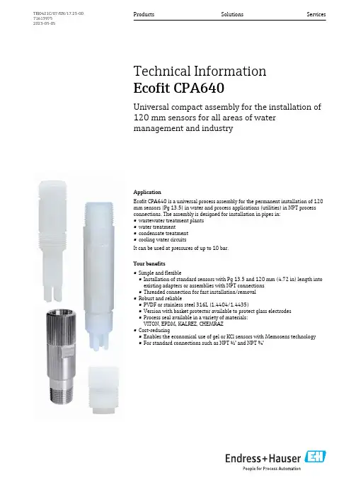
ApplicationEcofit CPA640 is a universal process assembly for the permanent installation of 120mm sensors (Pg 13.5) in water and process applications (utilities) in NPT process connections. The assembly is designed for installation in pipes in:•wastewater treatment plants •water treatment•condensate treatment •cooling water circuitsIt can be used at pressures of up to 10 bar.Your benefits•Simple and flexible•Installation of standard sensors with Pg 13.5 and 120 mm (4.72 in) length into existing adapters or assemblies with NPT connections •Threaded connection for fast installation/removal •Robust and reliable•PVDF or stainless steel 316L (1.4404/1.4435)•Version with basket protector available to protect glass electrodes •Process seal available in a variety of materials:VITON, EPDM, KALREZ, CHEMRAZ •Cost-reducing•Enables the economical use of gel or KCl sensors with Memosens technology •For standard connections such as NPT ½" and NPT ¾"Products Solutions ServicesTechnical Information Ecofit CPA640Universal compact assembly for the installation of 120 mm sensors for all areas of water management and industryTI00421C/07/EN/17.23-00716139752023-05-05Ecofit CPA6402Endress+HauserFunction and system designMeasuring systemA complete measuring system comprises:•Ecofit CPA640 installation adapter•Sensor with Pg 13.5, length 120 mm, e.g. Orbisint CPS11D •Transmitter, e.g. Liquiline CM42•Measuring cable, e.g. CYK101Measuring system with CPA640, transmitter (CM42), sensor and cable A Direct installation at NPT process connection B Installation in immersion assembly (CYA611)CInstallation in flow assemblyProcessPressure-temperature ratings2temperature/pressure ratings1Stainless steel 1.4404/1.4435 (AISI 316L), MONEL 2PVDFEcofit CPA640Mechanical construction3CPA640-A/B***. Unit of measurement mm (in)4CPA640-C/D***. Unit of measurement mm (in)Endress+Hauser3Ecofit CPA6405CPA640-E***. Unit of measurement mm (in)6CPA640-G/I***. Unit of measurement mm (in)Weight Approx. 0.1 to 0.3 kg (0.22 to 0.66 lbs) depending on the version4Endress+HauserEcofit CPA640Endress+Hauser 5MaterialsAdapter bodyCPA640-A/C/E/G***PVDF (polyvinylidenefluoride)CPA640-B/D***Stainless steel 316L (1.4404/14435))CPA640-I***MONEL Sealing ring FDM (VITON), EPDM, CHEMRAZ, KALREZEndress+Hauser supplies DIN/EN process connections with stainless steel threaded connection in accordance with AISI 316L (DIN/EN material number 1.4404 or 14435).In terms of their stability-temperature property, the materials 1.4404 and 1.4435 are grouped in EN 1092-1 table 18 under 13E0. The chemical composition of the two materials can be identical.Process connections•The assembly can only be installed if the process is unpressurized and the container is empty.•The assembly is designed for installation on containers or pipes.•Appropriate process connections must be provided for the installation.•Make sure the orientation is correct. Information can be found in the manual of the sensor used.Process connections depend on the assembly version:Assembly version Process connection CPA640-A/B***NPT ½"CPA640-C/D***NPT ¾"CPA640-E***NPT 1"CPA640-G/I***M25x1.5Ordering informationProduct page /cpa640Product Configurator1.Configure : Click this button on the product page.2.Select Extended selection .The Configurator opens in a separate window.3.Configure the device according to your requirements by selecting the desired option for each feature.In this way, you receive a valid and complete order code for the device.4.Apply : Add the configured product to the shopping cart.For many products, you also have the option of downloading CAD or 2D drawings of the selected product version.5.Show details : Open this tab for the product in the shopping cart.The link to the CAD drawing is displayed. If selected, the 3D display format is displayedalong with the option to download various formats.Scope of deliveryThe scope of delivery comprises:•Ordered version of assembly •Operating InstructionsEcofit CPA6406Endress+HauserCertificates and approvalsCurrent certificates and approvals for the product are available at on the relevant product page:1.Select the product using the filters and search field.2.Open the product page.3.Select Downloads .Ecofit CPA640Endress+Hauser 7AccessoriesThe following are the most important accessories available at the time this documentation was issued.Listed accessories are technically compatible with the product in the instructions.1.Application-specific restrictions of the product combination are possible.Ensure conformity of the measuring point to the application. This is the responsibility of the operator of the measuring point.2.Pay attention to the information in the instructions for all products, particularly the technical data.3.For accessories not listed here, please contact your Service or Sales Center.Sensors (selection)pH sensorsCeragel CPS71•pH electrode with reference system including ion trap•Product Configurator on the product page:/cps71Technical Information TI00245CMemosens CPS71E•pH sensor for chemical process applications •Digital with Memosens 2.0 technology•Product Configurator on the product page:/cps71eTechnical Information TI01496CCeraliquid CPS41•pH electrode with ceramic junction and KCl liquid electrolyte•Product Configurator on the product page:/cps41Technical Information TI00079CMemosens CPS41E•pH sensor for process technology•With ceramic junction and KCl liquid electrolyte •Digital with Memosens 2.0 technology•Product Configurator on the product page:/cps41eTechnical Information TI01495CMemosens CPS77E•Sterilizable and autoclavable ISFET sensor for pH measurement •Digital with Memosens 2.0 technology•Product Configurator on the product page:/cps77eTechnical Information TI01396ORP sensorsCeragel CPS72•ORP electrode with reference system including ion trap•Product Configurator on the product page:/cps72Technical Information TI00374CMemosens CPS72E•ORP sensor for chemical process applications •Digital with Memosens 2.0 technology•Product Configurator on the product page:/cps72eTechnical Information TI01576CEcofit CPA640Oxygen sensorsOxymax COS22•Sterilizable sensor for dissolved oxygen•With Memosens technology or as an analog sensor•Product Configurator on the product page:/cos22Technical Information TI00446CMemosens COS22E•Hygienic amperometric oxygen sensor with maximum measurement stability over multiple sterilization cycles•Digital with Memosens 2.0 technology•Product Configurator on the product page:/cos22eTechnical Information TI01619C*71613975*71613975。
AXT600 Spectrum ManagerManual for the Shure Axient Spectrum Manager (AXT600). Version: 4 (2019-L)Table of ContentsAXT600Spectrum Manager 3簡要 說明3特性 3前面板4後面板 5連接天線6安裝說明6主功能表螢幕6資料顯示螢幕 8頻譜管理器與接收機的連網8自動 IP 地址分配 9手動 IP 地址 9設備重置 9故障排除 9網路存取控制 10 RF 協調精靈10 All New 10 Update Freqs 10 Update Devices 10使用 All New 精靈選項進行系統設定11排除12輸入排除項目 12事件日誌12頻譜監控13備用頻率監控 13 Listen 13掃描 14設定風扇速度15韌件更新15規格15掃描時間 17 RF 輸入 17連網 18附件18提供的附件 18 Information to the user19重要安全事項! 19適用於所有耳筒的警告! 20警告 21認證21AXT600Spectrum Manager 簡要 說明Axient 頻譜管理器是一款功能強大的工具,它能夠為無線元件計算、分析並分配相容頻率。
頻譜管理器掃描 RF 環境,並使用獲得的資料為在網路中發現的所有無線頻道計算相容頻率。
可以從“相容頻率列表”中對已連網的無線系統進行編程,並且可以持續監控備用頻率,並根據訊號質量對頻率進行分級。
在使用過程中,頻譜管理器可以在發生干擾時將清晰的頻率分配給接收機。
內置的頻譜監控工具能夠提供對 RF 活動的可視化和音訊跟蹤。
特性帶寬掃描頻率管理器能夠在可用於無線音訊的整個 UHF 頻率範圍內掃描資料。
掃描過程使用兩組天線輸入完成,這兩組天線都具有直接適用於無線接收機的敏感度和解析能力。
相容頻率列表相容頻率列表 (CFL) 是一個可用頻率的列表,可通過頻譜管理器進行計算、查看及編輯或可從運行 Wireless Workbench 6 的電腦上生成。

VERSAEXPRESS RF-64064” LARGE FORMAT PrinterPure genius.The V ersaEXPRESS RF-640Productivity and reliability at a smart price.The Roland VersaEXPRESS™ RF-640 offers the perfect formula for digital printing success: high production speed, outstanding print quality, ease of use and unsurpassed reliability. The genius behind the RF-640 is reflected in its ability to quickly produce high quality graphics and prints, while keeping cost of operation low. That translates into increased output, satisfied customers and more money in your pocket.Advanced Productivity FeaturesEquipped with advanced productivity features, the RF-640 is ideal for any high production environment. It boasts advanced print control technology for quality imaging and color consistency, while adjustable media support brackets to handle narrow or wide rolls with equal ease. The innovative Roland Ink Switching System adds greater production capability by automatically switching from an empty 440 ml cartidge to a back-up cartridge when ink runs out, allowing you to change out cartridges right from the front of the machine without having to stop and restart the printer. Workflow and output are further enhanced by Roland’s user-friendly V ersaWorks® RIP software, which includes media profiles, nesting, cropping, predictive ink and media usage, and other powerful production tools. V ersaWorks also features built-in Roland Color System and PANTONE® libraries for easy and accurate color spot matching.State of the Art Print T echnologySpecially designed to take full advantage of Roland’s high-density, GREENGUARD Gold Certified UL 2818 Eco-Sol MAX® 2 inks, the RF-640 prints beautiful, saturated color with virtually no banding – even at higher speeds. A mirrored CMYKKYMC gold-plated print head firing seven different droplet sizes ensures stunning graphic results on a wide range of media at speeds up to 521 square feet per hour. Roland Intelligent Pass Control™ further enhances image quality by minimizing any trace of bleeding and ensuring precise media feeding between passes.T o learn more about the pure genius of the RF, view thevideo at /rf.Intelligent ImagingDelivers smooth gradations, high-fidelity images and flawless solid colorsRoland Printer Assist iPad appRemotely manage production, test printing, cleaning and moreThe Genius of SimplicityY ou don’t have to be a genius to use an RF-640. In fact, this printer’s innovative features and technological advancements make it incredibly easy to operate. With the Roland Printer Assist iPad app, you can even remotely manage production, test printing, and even cleaning functions from an iPad tablet. Additional features for increased ease of use and convenience include an easy-access front-loading ink cartridge system, media loading levers at both the front and back of the printer, and a take-up unit that supports media rolls up to 110 lbs.Smart SavingsThe RF-640’s design allows for low running costs and easy maintenance. Precise inkjet technology and new optimized profiles for Eco-Sol MAX 2 ink work together for efficient ink consumption. An automated cleaning function also minimizes ink usage, while helping to prolong print head life. As a result, the RF-640 is highly efficient in both production and standby modes. As proof of its unmatched reliability, the RF-640 is backed by Roland’s unmatched T wo-Y ear Trouble-Free Warranty.**Registration within 60 days and continuous exclusive use of Roland inks during the first two years of ownership is required to qualify for the free second year of limited warranty coverage. Additional T erms and Conditions apply. See /warranties for details.Engineered to image beautifully,the RF offers a rare combination of value and performance, making it a very smart purchasing decision. Talk about genius!Specifications subject to change. *Outdoor durability is based on accelerated weather tests. Results may vary depending upon location and application. Lamination may be required for some applications or environmental conditions.Roland DGA Corp. has licensed the MMP technology from the TPL Group.FOR ADDITIONAL PRODUCT INFORMATION AND FEATURES, OR TO REQUEST A SAMPLE PRINT , CALL 800-542-2307 OR VISIT /RF ROLAND DGA CORPORATION | 15363 BARRANCA PARKWAY | IRVINE, CALIFORNIA 92618-2216 | 800.542.2307 | 949.727.2100 | CERTIFIED ISO 9001:2008RDGA-RF-01 July 2014VERSAEXPRESS™ RF-640 INKJET PRINTER• Large-format printer with 64” width, built to provideunsurpassed printing performance, even when unattended, in demanding production environments• 8-channel print head with mirrored CMYKKYMC configuration virtually eliminates chromatic banding • Photorealistic printing up to 1440 dpi• Roland Intelligent Pass Control™ technology• High density Eco-Sol MAX® 2 ink produces rich, vibrant colors on coated or uncoated media > Wide gamut for dynamic color imaging > Increased density for rich, saturated colors> Fast drying, virtually oderless, and scratch resistant > Up to three years outdoor durability without lamination* > GREENGUARD Gold certified• Automated TU-3 media take-up system > Supports extended production runs> Adjustable right flange for easy centering of smaller rolls • Integrated two-stage heating system supports high-speed, volume production• Automatic cleaning cycles simplify maintenance • Roland VersaWorks® RIP software includedFor detailed features and specifications,visit /rf.PRODUCT SPECIFICATIONS> Automates workflow for easy operation and better productivity> Advanced color management tools, including built-in PANTONE® and Roland Color System libraries > Predictive ink calculator•Roland OnSupport sends production updates via text message or email or your computer, tablet or smart phone • Roland Printer Assist iPad app allows remote management of common printer functionsGet social with us.R。
Sun StorageT ek™ 6540 陣列站點準備指南Sun Microsystems, Inc.文件號碼 819-7089-112007 年 4 月修訂版 A請將您對本文件的意見提交至:/hwdocs/feedback請回收Copyright 2007 Sun Microsystems, Inc., 4150 Network Circle, Santa Clara, California 95054, U.S.A. 版權所有。
Sun Microsystems, Inc.對於本文件所述技術擁有智慧財產權。
這些智慧財產權包含 http: // /patents 中列示的一項或多項美國專利,以及在美國及其他國家/地區擁有的一項或多項其他專利或申請中專利,但並不以此為限。
本文件及相關產品在限制其使用、複製、發行及反編譯的授權下發行。
未經 Sun 及其授權人 (如果有) 事先的書面許可,不得使用任何方法、任何形式來複製本產品或文件的任何部分。
協力廠商軟體,包含字型技術,其著作權歸 Sun 供應商所有,經授權後使用。
本產品中的某些部分可能源自加州大學授權的 Berkeley BSD 系統的開發成果。
UNIX 是在美國和其他國家/地區之註冊商標,已獲得 X/Open Company, Ltd. 專屬授權。
Sun 、Sun Microsystems 、Sun 標誌、Java 、AnswerBook2、 、Sun StorEdge 、Sun StorageTek 與 Solaris 是 Sun Microsystems, Inc. 在美國及其他國家/地區的商標或註冊商標。
所有 SPARC 商標都是 SPARC International, Inc. 在美國及其他國家/地區的商標或註冊商標,經授權後使用。
凡具有 SPARC 商標的產品都是採用 Sun Microsystems, Inc. 所開發的架構。
OPEN LOOK 與 Sun™ Graphical User Interface (Sun 圖形化使用者介面) 都是由 Sun Microsystems, Inc. 為其使用者與授權者所開發的技術。
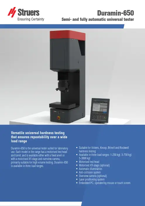
Duramin-650Semi- and fully automatic universal testerVersatile universal hardness testingthat ensures repeatability over a wideload rangeDuramin-650 is the universal tester suited for laboratory use. Each model in the range has a motorised test head and turret, and is available either with a fixed anvil or with a motorised XY-stage and overview camera, primarily suitable for high volume testing. Duramin-650 is available in three load ranges.• S uitable for Vickers, Knoop, Brinell and Rockwell hardness testing• A vailable in three load ranges: 1-250 kgf, 3-750 kgf, 5-3000 kgf• M otorised test head• M otorised XY-stage (optional)• A utomatic illumination• A nti-collision system• O verview camera (optional)• L aser positioning system• E mbedded PC, operated by mouse or touch screenAUSTRALIA & NEW ZEALAND Struers Australia27 Mayneview StreetMilton QLD 4064AustraliaPhone +61 7 3512 9600Fax +61 7 3369 8200****************** BELGIUM (Wallonie)Struers S.A.S.370, rue du Marché RollayF- 94507 Champignysur Marne CedexTéléphone +33 1 5509 1430Télécopie +33 1 5509 1449****************** BELGIUM (Flanders)Struers GmbH Nederland Zomerdijk 34 A3143 CT MaassluisTelefoon +31 (10) 599 7209 Fax +31 (10) 5997201********************** CANADAStruers Ltd.7275 West Credit Avenue Mississauga, Ontario L5N 5M9 Phone +1 905-814-8855Fax +1 905-814-1440****************CHINAStruers Ltd.No. 1696 Zhang Heng Road Zhang Jiang Hi-Tech Park Shanghai 201203, P.R. China Phone +86 (21) 6035 3900Fax +86 (21) 6035 3999******************CZECH REPUBLIC & SLOVAKIA Struers GmbH Organizační složka vědeckotechnický parkPřílepská 1920,CZ-252 63 Roztoky u Prahy Phone +420 233 312 625Fax +420 233 312 640******************************************* GERMANYStruers GmbHCarl-Friedrich-Benz-Straße 5D- 47877 WillichTelefon +49 (0) 2154 486-0 Fax +49 (0) 2154 486-222****************** FRANCEStruers S.A.S.370, rue du Marché RollayF-94507 Champignysur Marne CedexTéléphone +33 1 5509 1430Télécopie +33 1 5509 1449****************** HUNGARYStruers GmbH Magyarországi Fióktelepe2040 BudaörsSzabadság utca 117Phone +36 2380 6090Fax +36 2380 6091Email:****************** IRELANDStruers Ltd.Unit 11 Evolution@ AMP Whittle Way, Catcliffe Rotherham S60 5BLTel. +44 0845 604 6664Fax +44 0845 604 6651***************.ukITALYStruers ItaliaVia Monte Grappa 80/420020 Arese (MI)Tel. +39-02/38236281Fax +39-02/38236274*********************JAPANMarumoto Struers K.K Takanawa Muse Bldg. 1F3-14-13 Higashi-Gotanda, ShinagawaTokyo141-0022 JapanPhone +81 3 5488 6207Fax +81 3 5488 6237******************.jp NETHERLANDSStruers GmbH Nederland Zomerdijk 34 A3143 CT MaassluisTelefoon +31 (10) 599 7209Fax +31 (10) 5997201********************** NORWAYStruers ApS, NorgeSjøskogenveien 44C1407 VinterbroTelefon +47 970 94 285***************AUSTRIAStruers GmbH Zweigniederlassung Österreich Betriebsgebiet Puch Nord 85412 PuchTelefon +43 6245 70567Fax +43 6245 70567-78******************POLANDStruers Sp. z o.o.Oddział w Polsceul. Jasnogórska 4431-358 KrakówPhone +48 12 661 20 60Fax +48 12 626 01 46*****************ROMANIAStruers GmbH, Sucursala Bucuresti Str. Preciziei nr. 6R062203 sector 6, Bucuresti Phone +40 (31) 101 9548Fax +40 (31) 101 9549****************** SWITZERLANDStruers GmbH Zweigniederlassung Schweiz Weissenbrunnenstraße 41CH-8903 BirmensdorfTelefon +41 44 777 63 07Fax +41 44 777 63 09********************** SINGAPOREStruers Singapore627A Aljunied Road,#07-08 BizTech Centre Singapore 389842Phone +65 6299 2268Fax +65 6299 2661*********************SPAINStruers EspañaCamino Cerro de los Gamos 1 Building 1 - Pozuelo de AlarcónCP 28224 MadridTeléfono +34 917 901 204Fax +34 917 901 112********************* FINLANDStruers ApS, Suomi Hietalahdenranta 1300180 HelsinkiPuhelin +358 (0)207 919 430 Faksi +358 (0)207 919 431******************SWEDENStruers SverigeBox 20038161 02 BrommaTelefon +46 (0)8 447 53 90 Telefax +46 (0)8 447 53 99***************UNITED KINGDOMStruers Ltd.Unit 11 Evolution @ AMPWhittle Way, Catcliffe Rotherham S60 5BLTel. +44 0845 604 6664Fax +44 0845 604 6651***************.ukUSAStruers Inc.24766 Detroit Road Westlake, OH 44145-1598 Phone +1 440 871 0071Fax +1 440 871 8188****************Struers ApS Pederstrupvej 84DK-2750 Ballerup, Denmark Phone +45 44 600 800Fax +45 44 600 801******************Duramin-650 M1/M2/M3Duramin-650 AC1/AC2/AC3 LOADS AND APPLICATIONSModelLoad range (main loads)M11 kgf - 250 kgM23 kgf - 750 kgfM35 kgf - 3000 kgfAC11 kgf - 250 kgAC23 kgf - 750 kgfAC35 kgf - 3000 kgfVickers capability Yes YesKnoop capability Yes YesBrinell capabilty Yes YesRockwell capability Yes YesHVT/HBT Yes YesSTAGES AND TURRETSXY-stage Manual AutomaticXY-stage or anvil size (mm)ø 80350x265390x262390x262XY-stage stroke, max (mm)-220x160250x160250x160Vertical capacity (mm)300300Throat depth (mm)220220Motorized Z-axis Yes YesMotorized turret Yes YesTurret positions67Anti-collision protection Yes YesMachine weight255 kg260 kgCAMERAS AND OPTICSOverview camera No YesOverview cam FOV (mm)-200x160Overview camera resolution- 5 MPEvaluation camera resolution 5 MP 5 MPAuto illumination Yes YesStage illumination Yes YesLaser or LED guider-YesDual view No YesSOFTWARE AND MODULESJominy testing No YesCHD measurement Optional OptionalEdge detection No OptionalMapping No OptionalWelding module Optional OptionalKc fracture meas.Optional OptionalReport editor Yes YesData export Yes YesINTERFACES AND CONNECTIVITYOperation Embedded Windows 10 PC with 15" touch screen. Mouse and keyboard operation is optional.Communication Ports HDMI, VGA, RJ45, WLAN, USB, RS232WiFi Yes YesBlue tooth Optional Optional28.02.2019 / 62140663 Technical data。

G ENE C HIP® H YBRI DIZATI ON OV EN 640(110V & 220V M O DE LS)For research use onlyNot for diagnostic proceduresAffymetrix ConfidentialCopyright © 1999 Affymetrix, Inc. All rights reserved. Affymetrix, GeneChip, and the Affymetrixlogo are trademarks used by Affymetrix, Inc.P/N 700281, rev. 1GeneChip Hybridization Oven 640 Owner’s Manual i. . . . .. . . . . . . . . . . . . . . . . . . . . . . . . . . . . . . . . . .Contents GeneChip® Hybridization Oven 640 Owner’s ManualSafety. . . . . . . . . . . . . . . . . . . . . . . . . . . . . . . . . . . . . . . . . . . . . . . . . . . . . .1Customer Support Information . . . . . . . . . . . . . . . . . . . . . . . . . . . . . . . . . . .4Intended Use . . . . . . . . . . . . . . . . . . . . . . . . . . . . . . . . . . . . . . . . . . . . . . . .5Unpacking the GeneChip Hybridization Oven 640. . . . . . . . . . . . . . . . . . . .5Setting up the GeneChip Hybridization Oven 640 . . . . . . . . . . . . . . . . . . . .5Control Panel of the GeneChip Hybridization Oven. . . . . . . . . . . . . . . . . . .6Operating the GeneChip Hybridization Oven 640 . . . . . . . . . . . . . . . . . . . .8GeneChip Hybridization Oven 640 Specifications . . . . . . . . . . . . . . . . . . .11Ordering and Technical Support Information . . . . . . . . . . . . . . . . . . . . . . .12ii GeneChip Hybridization Oven 640 Owner’s Manual P/N 700281, rev. 1P/N 700281, rev. 1GeneChip Hybridization Oven 640 Owner ’s Manual 1G ENE C HIP ® H YBRIDIZATION O VEN 640 . . . . .. . . . . . . . . . . . . . . . . . . . . . . . . . . . . . . . . . .O WNER ’S M ANUAL. . . . . . . . . . . . . . . . . . . . . . . . . . . . . . . . . . . . . . . . . . . . . . . . . . . .S A F E T Y This manual contains information which must be read and understoodbefore using the equipment. When you come to an area which has one of the following symbols, pay particular attention and make certain to heed the safeguard.This symbol indicates a potential hazard which may cause serious injury or loss of life. Important safety information will follow.This symbol indicates a potential hazard to you or to the equipment.Important information that tells how to prevent damage to the equipment or how to avoid causes of minor injuries will follow.WARNINGCAUTIONG E N E C H I P ® H Y B R I D I Z A T I O N O V E N 640 O W N E R ’S M A N U A L Safety2GeneChip Hybridization Oven 640 Owner ’s ManualP/N 700281, rev. 1General Safety SummaryReview the following safety precautions to avoid injury and to preventdamage to this product or any products connected to it. To avoid potentialhazards, use this product only as specified.Only qualified personnel should perform service procedures.T o A v o i d F i r e o r P e r s o n a l I n j u r y•Use Proper Power Cord .Use only the power cord and plug specified for this product and certifiedfor the country of use.•Ground the Product .This product is grounded through the grounding conductor of the powercord. To avoid electrical shock, the grounding conductor must beconnected to earth ground.•Observe All Electrical Ratings .To avoid fire or shock hazard observe all further ratings informationbefore making connections to the product.•Do Not Operate Without Covers .DO NOT operate this product with covers or panels removed.•Use Proper Fuse .Use only the fuse type and rating specified for this product.•Avoid Exposed Circuitry .DO NOT touch exposed connections and components when power ispresent.•Do Not Operate With Suspected Failures .If you suspect there is damage to this product, have it inspected by. . . . .G E N E C H I P ® H Y B R I D I Z A T I O N O V E N 640 O W N E R ’S M A N U A L Safety P/N 700281, rev. 1GeneChip Hybridization Oven 640 Owner ’s Manual3qualified service personnel.•Do Not Send Your Instrument Elsewhere For Service Or Attempt To Service It Yourself . To protect your warranty and ensure safe operation, the instrument should be serviced only by Affymetrix or its representatives. If the instrument is not working correctly, please contact your Affymetrix Technical Support Representative.•Do Not Operate in Wet or Damp Conditions.•Do Not Operate in an Explosive Atmosphere.•Keep Product Surfaces Clean and Dry.•Provide Proper Ventilation . Refer to the manual ’s installation instructions for details on installing the product so it has proper ventilation.Terms on the Product The following terms may appear on the product:DANGER - indicates an injury hazard immediately accessible as you read the marking WARNING - indicates an injury hazard not immediately accessible as you read the marking CAUTION - indicates a hazard to property including the productG E N E C H I P ® H Y B R I D I Z A T I O N O V E N 640 O W N E R ’S M A N U A L Customer Support Information4GeneChip Hybridization Oven 640 Owner ’s ManualP/N 700281, rev. 1Symbols on the ProductThe following symbols may appear on the product:CAUTION - Refer to manualCAUTION - Hot surface. . . . . . . . . . . . . . . . . . . . . . . . . . . . . . . . . . . . . . . . . . . . . . . . . . . .C U S T O M E R S U P P O R T I N F O R M A T I O NUnited States:Affymetrix, Inc.3380 Central ExpresswaySanta Clara, CA 95051Telephone Toll free: 888-DNA-CHIP; or 888-362-2447; or 408-731-5503Fax: 408-481-0435Europe:Affymetrix UK Limited7200 The QuorumOxford Business Park NorthOxfordOX4 2JZUnited KingdomTel: +44 (0)7000 785 803Fax:+44 (0)7000 785 804E-Mail:**********************. . . . .G E N E C H I P ® H Y B R I D I Z A T I O N O V E N 640 O W N E R ’S M A N U A L Intended UseP/N 700281, rev. 1GeneChip Hybridization Oven 640 Owner ’s Manual5. . . . . . . . . . . . . . . . . . . . . . . . . . . . . . . . . . . . . . . . . . . . . . . . . . . .I N T E N D E D U S E The GeneChip Hybridization Oven 640 is for research use only. It is notintended for diagnostic procedures.. . . . . . . . . . . . . . . . . . . . . . . . . . . . . . . . . . . . . . . . . . . . . . . . . . . .U N P A C K I N G T H E G E N E C H I P H Y B R I D I Z A T I O N O V E N 640Carefully remove the oven and accessories from the shipping container.Use proper lifting techniques or a lifting aid to prevent injury (see NIOSHGuide for Manual Lifting ). If there are any signs of damage duringshipping, immediately notify Affymetrix Technical Support. If possible,save the shipping container for future transit requirements.. . . . . . . . . . . . . . . . . . . . . . . . . . . . . . . . . . . . . . . . . . . . . . . . . . . .S E T T I N G U P T H E G E N E C H I P H Y B R I D I Z A T I O N O V E N 640Locate the oven on a stable, level surface capable of holding a minimum of100 lbs. (45.5 Kg). Once the oven is in place, it should be levelled using theadjustable feet. The oven should be located with a minimum clearance of2 inches (5.1 cm) on each side, 2 inches (5.1 cm) on the back, and3 inches(7.6 cm) on the top.The 110 V unit is supplied with a three-prong electrical plug, and should beplugged into a properly grounded electrical outlet. The 220V unit issupplied with a three conductor power cord without plug. The appropriateplug (not supplied) certified for the country of use should be attached to thepower cord in accordance with local regulations.G E N E C H I P ® H Y B R I D I Z A T I O N O V E N 640 O W N E R ’S M A N U A L Control Panel of the GeneChip Hybridization Oven6GeneChip Hybridization Oven 640 Owner ’s ManualP/N 700281, rev. 1CA U T I O NThe power supply cord is used as the main disconnect device. Ensure thatthe socket outlet is located and installed near the equipment and is easilyaccessible.A T T E N T I O NLe cordon d ’alimentation est utilise ’ comme interrupteur general. La prisede courant doit etre situe ’e ou installe ’e a proximite ’ du materiel et etrefacile d ’acce ’s.A C H T U N GZur sicheren Trennung des Ger ätes vom Netz ist der Netzstecker zu ziehen.Vergewissern Sie sich, da ß die Steckdose leicht zug änglich ist.. . . . . . . . . . . . . . . . . . . . . . . . . . . . . . . . . . . . . . . . . . . . . . . . . . . .C O N T R O L P A N E L O F T H E G E N E C H I P H Y B R ID I Z A T I O N O VE NThe control panel instrument contains 6 items:•SPEED CONTROL knob (controls speed of rotation of carouselbetween 0 and 80 RPM).•SPEED CONTROL DISPLAY (displays the speed of rotation of thecarousel)CAUTION. . . . .G E N E C H I P ® H Y B R I D I Z A T I O N O V E N 640 O W N E R ’S M A N U A L Control Panel of the GeneChip Hybridization OvenP/N 700281, rev. 1GeneChip Hybridization Oven 640 Owner ’s Manual7•JOG button (moves carousel from one bottle position to the next tofacilitate adding and removing GeneChip Cartridge Carriers).Note: JOG button will not operate if SPEED CONTROL is set at “0”.•POWER switch (turns on main power; must be in ON [I] position forHEAT switch to be activated. The JOG button can only be activated withPOWER switch in the ON [I] position).•HEAT switch turns on heat as controlled by TEMP CONTROL.•TEMP CONTROL controls temperature when HEAT switch is in ONposition.The TEMP CONTROL is extremely easy to operate. There are 2 displaysand 6 buttons. The bottom red display is the “set ” temperature and the topgreen display is the actual temperature. The 6 buttons control the “set ”temperature, one button to increase and one button to decrease each of thethree digits. The temperature can be set anywhere between 00.0° and95.0° C.It is recommended that the maximum temperature setting not exceed 70° C.Also for good performance, the temperature setting should be at least 5° Cabove room temperature.For example, to set the temperature at 45.2° C, set the first digit (on the leftside) to “4” using the + (increase) and - (decrease) left hand pair of buttons;CAUTIONG E N E C H I P ® H Y B R I D I Z A T I O N O V E N 640 O W N E R ’S M A N U A L Operating the GeneChip Hybridization Oven 6408GeneChip Hybridization Oven 640 Owner ’s ManualP/N 700281, rev. 1then set the second digit to “5” using the middle set of buttons; and finallyset the third decimal digit to “2” using the right hand set of buttons. If theset temperature is higher than the actual temperature, the heater willimmediately come on and the temperature will rapidly rise to the settemperature with virtually no over shoot. The practical temperature range isambient to 70° C. Since there is no refrigerator mechanism in thisinstrument, the chamber cannot be cooled below ambient temperature.While the chamber temperature can be heated to 95.0° C, prolongedtemperatures above 60° C have been shown to have deleterious effects onGeneChip Cartridges.. . . . . . . . . . . . . . . . . . . . . . . . . . . . . . . . . . . . . . . . . . . . . . . . . . . .O P E R A T I N G T H E G E N E C H I P H Y B R I D I Z A T I O N O V E N 6401Loading GeneChip cartridges into the GeneChip Cartridge Carrier:Eight (8) GeneChip cartridges can be loaded into each GeneChip CartridgeCarrier. GeneChip Cartridge Carriers are included as accessories with eachoven. The GeneChip Cartridge Carrier is “keyed ” such that the GeneChipcartridges can be loaded only one way. Additional Cartridge Carriers canbe purchased from Affymetrix.2Loading the GeneChip Cartridge Carrier into the oven:Up to eight (8) Carriers can be loaded into the oven. The Carrier is pushedinto the slots facing outwards, away from the shaft. The Carrier is pushedinto the slots until a “click ” is heard and the Carrier is captured.. . . . .G E N E C H I P ® H Y B R I D I Z A T I O N O V E N 640 O W N E R ’S M A N U A L Operating the GeneChip Hybridization Oven 640P/N 700281, rev. 1GeneChip Hybridization Oven 640 Owner ’s Manual9It is recommended that the user confirm the capture of the carrier by gentlyattempting to withdraw the Carrier. If the Carrier can be withdrawn, it was not properly captured and the Carrier loading process must be repeated.It is recommended that Carriers should be loaded in even numbers with each pair of carriers placed 180° apart across the shaft to maintain balance. If loading an odd number of Carriers (1,3,5,7) an empty Carrier should be loaded to balance the carousel.When the POWER is ON (I) the JOG button is operable at all times if the SPEED CONTROL knob is set above “0” EVEN WHEN THE DOOR IS OPEN . The user must keep all hands and fingers away from the carousel when operating the JOG button during loading and unloading of Carriers.3Turn the POWER switch to the ON (I) position.The power switch must be ON before the HEAT switch can be activated 4The oven door must be closed and locked before carousel will rotate!CAUTION CAUTION WARNINGG E N E C H I P ® H Y B R I D I Z A T I O N O V E N 640 O W N E R ’S M A N U A L Operating the GeneChip Hybridization Oven 64010GeneChip Hybridization Oven 640 Owner ’s ManualP/N 700281, rev. 15Use the SPEED CONTROL knob to set the rotation speed of the carouselas recommended in the GeneChip assays. The range is 0-80 RPM.For hybridization, a rotation speed of 60 RPM is commonly used.6Turn the HEAT switch to the ON (I) position.You can now set the temperature as required using the TEMP CONTROLas described in the CONTROL PANEL section above. If the “set ”temperature is higher than the chamber temperature, the oven will heatrapidly to the “set ” temperature. The controller has been programmed toslow down the rate of heating as the chamber temperature approaches the“set ” temperature, so there is very little overshoot.7To unload the Carriers from the oven, the rotation of the carousel can bestopped by setting the SPEED CONTROL to “0” or by simply openingthe oven door.The carousel can then be rotated manually or by using the JOG button tomove the position of the Carrier to be unloaded. The Carrier is removedfrom the carousel by grasping the large flange and giving a sharp pull onthe Carrier unlocking it from the capture mechanism. The Carrier can thenbe completely removed by sliding it from the carousel.. . . . .G E N E C H I P ® H Y B R I D I Z A T I O N O V E N 640 O W N E R ’S M A N U A L GeneChip Hybridization Oven 640 SpecificationsP/N 700281, rev. 1GeneChip Hybridization Oven 640 Owner ’s Manual11. . . . . . . . . . . . . . . . . . . . . . . . . . . . . . . . . . . . . . . . . . . . . . . . . . . .G E N E C H I P H Y B R I D I Z A T I O N O V E N 640 S P E C I F I C A T I O N SPhysical Dimensions:Height19 inches Width18 inches Depth15 inches Weight 50 pounds (22.68 Kg)Power Requirements:Input Voltage90V - 132V @ 47 hz - 65 hz (110V Model)190V - 264V @ 47 hz - 65 hz (220 Model)Input Power less than 1000 VA (110 V, 220 V Models)Environmental Requirements:Operating Temperature Range15° C to 30°Operating Humidity range 15% to 85% Relative HumidityPerformance Requirements:Carousel Rotation Speed0 - 80 RPM Oven Setpoint RangeAmbient + 5° C to 70° C Oven Temperature Precision±0.4° C at Calibration Setpoint Oven Temperature Accuracy ±2.0° from display temp over range of 30° C to 60° CRegulatory Requirements :The Oven meets applicable CSA standards for North America (C22.2 No. 1010).The oven meets applicable IEC standards for safety (IEC 1010-1).The oven meets applicable directives (LVD and EMC) for the European Union CE Mark (EN 55011:Emissions, EN 61000-4-2:ESD, EN 61000-4-3:Radiated Immunity, EN 61000-4-4:EFT/B, EN 61010-1:Low Voltage).The oven is Year 2000 Compliant.G E N E C H I P ® H Y B R I D I Z A T I O N O V E N 640 O W N E R ’S M A N U A L Ordering and Technical Support Information12GeneChip Hybridization Oven 640 Owner ’s ManualP/N 700281, rev. 1. . . . . . . . . . . . . . . . . . . . . . . . . . . . . . . . . . . . . . . . . . . . . . . . . . . . OR D E R I N G A N D T E C H N I C A L S U P P O R T I N F O R M A T I O NFor technical inquiries, contact your technical support team:TRADEMARKSGeneChip ®, Affymetrix ®,, and aretrademarks used by Affymetrix, Inc.GeneArray ™ is a U.S. trademark of Hewlett-Packard Company.North AmericaEurope Affymetrix Inc.3380 Central ExpresswaySanta ClaraCA 95051USATel: 888-DNA-CHIP (888-362-2447)Fax: 408-481-0435E-mail:********************** Affymetrix UK Limited 7200 The Quorum Oxford Business Park North Oxford OX4 2JZ United Kingdom Tel: +44 (0)7000 785 803Fax:+44 (0)7000 785 804Amersham Pharmacia Biotech Ltd.Amersham Place Little Chalfont Buckinghamshire, HP7 9NA England Tel: +44-(0) 1494-543755Fax: +44-(0) 1494-543278Email: ************************.. . . . .G E N E C H I P ® H Y B R I D I Z A T I O N O V E N 640 O W N E R ’S M A N U A L Ordering and Technical Support Information P/N 700281, rev. 1GeneChip Hybridization Oven 640 Owner ’s Manual13LIMITED LICENSEPROBE ARRAYS, INSTRUMENTS, SOFTWARE, AND REAGENTS ARE LICENSED FOR RESEARCH USE ONLY. NO RIGHT TO MAKE, HA VE MADE, OFFER TO SELL, SELL, OR IMPORT OLIGONUCLEOTIDE PROBE ARRAYS OR ANY OTHER PRODUCT IN WHICH AFFYMETRIX HAS PATENT RIGHTS IS CONVEYED BY THE SALE OF PROBE ARRAYS, INSTRUMENTS, SOFTWARE, OR REAGENTS HEREUNDER. THIS LIMITED LICENSE PERMITS ONLY THE USE OF THE PARTICULAR PRODUCT(S) THAT THE USER HAS PURCHASED FROM AFFYMETRIX.COPYRIGHT©1999 Affymetrix, Inc. All rights reserved.。
高斯计特斯拉计电子档说明书范文(总8页)-CAL-FENGHAI.-(YICAI)-Company One1-CAL-本页仅作为文档封面,使用请直接删除WT10A数字特斯拉计使用说明书WT10A数字特斯拉计使用说明书感谢您购买"韦特"系列数字特斯拉计/高斯计.本使用说明书简扼介绍了此机之各项功能,让您操作自如,请您在使用前仔细阅读本使用说明书.一.概述WT10系列便携式数字特斯拉计分为WT10A、 WT10B 、WT10C、WT10D、WT10E、WT10F六种类型可用于测量直流磁场、交流磁场、辐射磁场、剩磁、地球磁场等等各类磁场的磁感应强度。
该仪器可以随身携带(150mm×70mm×30mm),量程范围宽,操作方便,液晶显示清晰,按键均采用国内最先进的触摸式按键,大大增强了其使用寿命和使用舒适度。
电源为六节5号干电池,可连续工作100多个小时,也可在市电的情况下使用稳压电源,小巧便携。
完善的质量保证,优质的售后服务,是您工作的理想选择。
特斯拉计是检测磁体磁感应强度的专用仪器,是磁性测量领域中用途最为广泛的测量仪器之一。
WT10A便携式数字特斯拉计可用于测量直流磁场、扬声器、磁选机、永磁除铁器的工作磁场以及泄漏磁场,零部件机加工后的退磁剩磁场等各类磁场的磁感应强度。
该仪器可以随身携带,量程范围宽,操作方便,液晶显示清晰。
实际工作领域:1.永磁材料的表面磁场分布(即我们通常所说的测量表磁);2.磁路结构内的间隙磁场;3.通过永磁或直流电流产生磁场作用于吸取铁磁材料的设备所产生的磁场(例如:除铁器、磁选机、磁力吸盘、电磁铁、退磁器)等等;二.工作原理本系列仪器采用的是基于霍尔效应原理制成的传感器,即霍尔传感器。
传感器有横向、轴向二种,用户可根据需求选择或另配;电路采用低漂移的放大器以及高稳定度的供电电源、31/2液晶显示屏显示测量值。
(一)霍尔效应原理将金属或半导体薄片置于磁场中,当有电流通过时,在垂直于电流和磁场的方向上将产生电动势,这种物理现象称为霍尔效应。
第二部分使用说明书(2003.1)目次注意事项……………………………………………………………………………………………1 装置介绍 (1)1.1 面板布置 (1)1.2 键盘简介 (2)1.3 信号灯简介 (3)1.4 串行接口 (4)1.5 操作区简介 (4)1.6 出厂铭牌 (5)1.7 背板及端子简介 (6)2 菜单操作 (14)2.1 功能简介 (14)2.2 操作说明 (16)3 用户调试大纲 (33)3.1 装置通电前检查 (33)3.2 绝缘检查 (33)3.3 上电检查 (33)3.4 采样精度检查 (33)3.5 接点输出校验 (33)3.6 定值校验 (34)3.7 跳合闸电流保持试验 (34)3.8 相序检查 (34)3.9 校准时钟 (34)4 事件信息一览表 (35)4.1 PSL 640系列保护事件信息一览表 (35)4.2 PSL 640系列保护告警事件信息一览表(告警、呼唤为相同的灯光信号) (35)4.3 PSL 640保护压板信息一览表 (36)4.3 PSL 640保护压板信息一览表 (36)4.4 PSL 640保护遥测量信息一览表 (36)4.5 PSL 640保护遥信量信息一览表 (37)5 附图 (38)·注意事项·注意事项为防止电源损坏,保护各功能插件,请不要带电插拔各模块。
对保护进行测试时,请使用可靠的测试仪,进行测试,推荐使用OMCRON 56综合测试仪。
如遇装置异常,请与我公司联系。
操作密码:99请注意保密。
以免由于密码泄露,造成误操作。
1 装置介绍1.1 面板布置1.2 键盘简介PS 640系列保护装置键盘示意图1.3 信号灯简介1.4 串行接口PS 系列装置PC 机1.5 操作区简介51.6 出厂铭牌1.7 背板及端子简介1.7.1 端子布置图1.7.2 交流输入端子说明注意:1)I0、I0’为小电阻接地系统零序电流输入端,电流输入范围为100mA ~20A ,故不宜采用Ia ,Ib ,Ic 求和的方式产生I0;I0c 为小电流接地系统方式时接地选线用零序电流输入端。
用户使用手册USER MANUALDX-360三维数字高斯计DIGTAL GAUSS METER厦门盈德兴磁电科技有限公司 Xiamen Dexing Magnet Technology Co.,Ltd一、公司介绍厦门盈德兴磁电科技有限公司是一家专业从事全数字化自动化测磁系统,高精度数字磁检测设备及数字磁场控制的科技型公司。
依托中科院的先进技术研发和生产高精度一维,二维和三维霍尔探头(带温度补偿)及多维高精度高分辨力测磁仪并通过ISO9001及IQNET国际体系认证,多项性能及参数均可达到国际先进水平。
且多次被航天、军工、航海、科研及院校应用, 并受到广泛的好评。
我公司可以根据用户的需求,研发、生产多种测磁系统,包括多点阵列磁扫描系统和工业自动化检测系统,远程有线与无线控制系统,磁屏蔽系统,地磁补偿系统和特种高斯计、磁通门计、高精度磁场控制平台、计量检定系统(我公司使用的精度为:读数的±0.002%——±0.0002%)、多维磁场分析扫描系统、多维电机磁场测试分析系统、多极磁环测试系统、地磁屏蔽测磁系统、多点阵列磁扫描系统、霍尔效应测试系统、线圈及电磁铁等等定制产品。
同时代理国际尖端测磁仪器公司产品。
二、地理位置地址:厦门市湖里区安岭路992号网址:三、文档说明本文档公开和描述的方法及装置由厦门盈德兴磁电科技有限公司独立资金支持并开发,不存在任何其它契约形式支持,并且不存在可能通过任何途经影响或削弱厦门盈德兴磁电科技有限公司知识产权的任何关系。
厦门盈德兴磁电科技有限公司保留在不事先通知的情况下,在任何时间添加、改进、变更或收回设备功能、变更设计、变更产品或变更产品的说明书、用户手册等文档的权利。
厦门盈德兴磁电科技有限公司不对本文档所含错误、或者偶然事件,或者由于产品配置、性能或由于使用本文档所造成的损失负责。
四、有限保修担保本产品之制造商厦门盈德兴磁电科技有限公司对此产品由发货之日起12个月内实行保修。
IR VIDEO THEMOMETERAX-7550Manual10-07/9862INTRODUCTIONThank you for purchasing the IR VIDEO Thermometer which is capable of non-contact (infrared) temperature measurements with visual camera at the touch of a button. The built-in laser pointer increases target accuracy while the backlight LCD and handy push-buttons combine for convenient, ergonomic operation.The IR VIDEO Thermometer can be used to measure the surface temperature of the objects that is improper to be measured by traditional (contact) thermometer (such as moving object, the surface with electricity current or the objects which are uneasy to be touched.)Proper use and care of this meter will provide years of reliable service.FEATURES:• 2.2” TFT LCD display•640*480pixels:30 million pixels)•Micro SD memory card•Image (JPEG) and video (AVI)•Humidity and Air Temperature•Dual laser targeting•Type-K thermocouple probe•Adjustable emissivity•High accuracy•Fast response time•Dewpoint temperature and Wet bulb temperatureDistance & Spot SizeAs the distance (D) from the object increases, the spot size (S) of the area measured by the unit becomes larger. The relationship between distance and spot size for each unit is listed below. The focal point for each unit is 914mm (36”). The spot sizes indicate 90% encircled energy.Specifications1.IR temperature measurement℃℉Temperature Range:-50 to 1600 (-58 to 2912)D: S:50:1℃℉℃℉20 to 500 (68 to 932) Accuracy:±1%±1.0 (1.8):℃℉±1.5%:500 to 1000 (932 to 1832)℃℉±2% 1000 to 1600(1832 to 2912)℃℉-50 to 20(-58 to 68)℃℉±3.5 (6.3)℃℉1000Display resolution:0.1 (0.1)℃℉>10001 (1)℃℉-50 to 20 (-58 to 68)℃℉Repeatability:±1.5 (2.7):℃℉20 to 1000 (68 to 1832)℃℉±0.5% or ±0.5 (0.9)℃℉±1% 1000 to 1600(1832 to 2912) Response Time:150mSSpectral Response:8 ~14umEmissivity:Digitally adjustable form 0.10 to 1.002.Type-k temperature measurement℃℉Temperature Range:-50 to 1370 (-58 to 2498)℃℉Accuracy:±0.5%±1.5 (2.7)℃℉0 to 1370 (32 to 2498)℃℉℃℉-50 to 0 (-58 to 32)±2.5 (4.5)℃℉<1000Display resolution0.1 (0.1)℃℉>10001 (1)3.Air temperature and Relative Humidity measurement℃℉Air Temperature Range:0 to 50 (32to 122)℃℉Dewpoint Temperature Range:0 to 50 (32to 122)Relative Humidity Range:0 to 100% RH℃℉℃Air temperature Accuracy:±0.5 (0.9) 10 to 40℃℉others±1.0 (1.8)℃℉10 to 40℃Dewpoint temperature Accuracy:±0.5 (0.9)℃℉others±1.0 (1.8)Relative Humidity Accuracy:±3%RH40% to 60%±3.5%RH0%to40%and 60%to 80%±5%RH0%to20%and 80%to 100%Operating Temperature:0 to 50 (32 to 122)℃℉Storage Temperature:-10 to 60 (14 to 140)℃℉Relative Humidity:10 to 90%RH non-condensingDisplay:2.2” 320*240 color LCD with backlight POWERBattery:Rechargeable battery Battery Life:About 4 hours continuous useBattery Charge Time:About 2 hours with AC adapter or USB connection Size (H*W*L):205mm*62mm*155mm Weight:410gMenu OverviewPower on or power offOn the power off mode, press and hold ESC button, until the LCD is on, then the unit will power on. On the power on mode, Press and hold the ESC button, until the LCD is off, then the unit will power off.1.Measurement ModeThe IR VIDEO thermometer has six modes.On the power on mode, press the ESC button, the unit will display the six modes. You can use UP or DOWN button to select any mode you need.Symbol Description Symbol DescriptionCAM mode High alarmIR mode High alarm workingDEWPOINT mode Low alarmLaser Low alarm workingScan Hold2.CAM modeUse to measure IR temp, air temp, air humi, dewpoint temperature and wet bulbtemperature with camera. It is can display the IR MAX temp., MIN temp., DIF temp., AVGtemp.Press and hold trigger to measure the temperature. This mode can take picture and takevideo.2.1.Take picture function2.2.Take video function▼ button to take videos, or press ESC button to esc.Press STOP with ▼button to stop the video.3.IR modeUse to measure IR temp, air temp, air humi, dewpoint temperature and wet bulb temperaturewithout camera. It is can display the IR MAX temp., MIN temp., DIF temp., AVG temp.Press and hold trigger to measure the temperature.4.DEWPOINT modemeasure the IR temp. and dewpoint temp.Press and hold trigger to measure the temperature.This is that the IR temperature and dewpoint temperature close to the percentage of5.Data logIn the DATALOG mode, first set the parameter, like high alarm value, low alarm value, interval time, and the line color, then press the trigger to start logging. The unit will automatically record data,press the ESC buttom to esc the DATALOG mode, then the data will automatically save.5.1.Set the datalog parameterSet high alarm valuePress the ENTER button , use the ▲ and ▼ button to adjust the value, then press theENTER button to confirm.Set low alarm valuePress the ENTER button , use the ▲ and ▼ button to adjust the value, then press theENTER button to confirm.Set interval timePress the ENTER button , use the ▲ and ▼ button to adjust the value, then press theENTER button to confirm.Select the colorPress the ENTER button, use the ▲ and ▼ button to select the color, then press the ENTER button to confirm6.GalleryPress the and button to select the picture, video or Logs. Then press the ENTER button to enter.In the picture .video or logs, press the ENTER button to view picture, play video or view log. Thenpress the ENTER button to delete the picture, video or log. Press the button to confirm to delete, press button to cancel.7.SETTINGSPress the and button to select the value, press the ENTER button to set the next value, press ESC button to esc and save the date and time.7.2.Units(C/F)Press the and button to select the unit, press the ESC button to esc and save. nguagePress the and button to select the language, press the ESC button to esc and save.7.4.Font ColorPress the and button to select the color, press the ESC button to esc and save.7.5.CursorPress the and button to select the cursor (off, cross or circle), press the ESC button to esc and save.7.6.BacklightPress the and button to select the backlight brightness, press the ESC button to esc and save.7.7.Auto Power offPress the and button to select the auto power off time or never auto power off, press the ESC button to esc and save.7.8.Screen TimeoutPress the and button to select the screen auto off time or never screen auto off, press the ESC button to esc and save.7.9.Keypress AlertPress the and button to enable or disable the keypress alert, press the ESC button to esc and save.7.10.Memory StatusPress the and button to select the memory (Device Memory or SD Card). Press the ESC button to esc and save.NOTE: If SD card inserted, SD card will be selected by defaultFormat: Select Device Memory or SD card and press the ENTER button to enter format mode, and then press ▲ button to confirm format or press ▼ button to cancel format,.7.11.Factory SettingPress the and button to select yes or no restore factory settings. Press the ESC button to esc and save.FUNCTIONOn any mode, press the ENTER button into the menu.Measure setEmissivity setON the first line (ε=0.94),,press the ENTER button to adjust emissivity, Press the and button to adjust the value, then press the ENTER button conform. Press the and button to select the emissivities of the materials, press the ESC button to esc and save.Alarm HighPress the and button to Enable or Disable the high alarm. If the high alarm is enable, press the ENTER button to enter adjustment, press the and button to adjust the value. Press the ENTER button to conform, press the ESC button to esc and save.Alarm LowPress the and button to Enable or Disable the low alarm. If the low alarm is on, press the ENTER button to adjust, press the and button to adjust value. Press the ENTER button to conform, press the ESC button to esc and save.LaserPress the and button to enable or disable laser, press the ESC button to esc and save.Auto ModePress the and button to enable or disable auto mode, press the ESC button to esc and save. If enable the auto mode, the unit will automatic continue measure, on the status, press the ENTER button, and then press UP button to exit the lock status, press the DOWN button to on or off the laser.Max/MinPress the and button to on or off display the max. or min. IR temperature ,press the ESC button to esc and save.Average/DifPress the and button to on or off display the average or difference of IR temp. , press the ESC button to esc and save.Ambient TEMP/% RHPress the and button to on or off display the air temperature and humidity, press the ESC button to esc and save.Dewpoint/wet bulbPress the and button to on or off display the dewpoint and wet bulb temperature, press the ESC button to esc and save.Type kPress the and button to enable or disable Type k input, and then press the ESC button to esc and save.NOTE: If insert Type-k probe, Enable will be selected by default. Users can select the Disable, prohibiting LCD display Type-k temperature.N NOTES:•How it WorksInfrared thermometers measure the surface temperature of an object. The unit’s optics sense emitted, reflected, and transmitted energy, which is collected and focused onto a detector.The unit’s electronics translate the information into a temperature reading, which is display on the unit. In units with a laser, the laser is used for aiming purposes only.•Field of ViewMake sure that the target is larger than the unit’s spot size. The smaller the target is, thecloser you should be to it. When accuracy is critical, make sure the target is at least twice as large as the spot size.•Distance & Spot SizeAs the distance (D) from the object increases, the spot size (S) of the area measured by the unit becomes larger. See: Fig: 1.•Locating a hot SpotTo find a hot spot aim the thermometer outside the area of interest, then scan across with an up and down motion until you locate hot spot.•Reminders1.Do not use the unit to measure shiny or polished metal surfaces (stainless steel,aluminum, etc.).See Emissivity2.The unit cannot be measured through transparent surfaces such as glass. It will measurethe surface temperature of the glass instead.3.Steam, dust, smoke, etc., Can prevent accurate measurement by obstructing the unit’soptics.•EmissivityEmissivity is a term used to describe the energy-emitting characteristics of materials.Most (90% of typical applications) organic materials and painted or oxidized surfaces have an emissivity of 0.95 (pre-set in the unit). Inaccurate readings will result from measuring shiny or polished metal surfaces. T o compensate, cover the surface to be measured with masking tape or flat black paint. Allow time for the tape to reach the same temperature as the material underneath it. Measure the temperature of the tape or painted surface.Emissivity ValuesMAINTENANCE•Repairs or service are not covered in this manual and should only be carried out by qualified trained technician.•Periodically, wipe the body with a dry cloth. Do not use abrasives or solvents on this instrument.•For service, use only manufacturer’s specified parts.。
Model 640 Series IndicatorsUser InstructionsNORTH AMERICA43108-0019 Issue AE October2009Weigh-Tronix 640 and 640M and 640XL Indicator user ManualTable of Contentspage Chapter 1 General Information and Warnings (5)About this manual (5)Installation (6)Safe handling of equipment with batteries (6)Routine maintenance (6)Cleaning the machine (7)Training (7)Sharp objects (7)FCC and EMC declarations of compliance (8)Chapter 2 Introduction (10)Front Panel (10)Key Descriptions (11)Annunciators (11)Display Messages (12)Numeric Entry Procedure (13)Getting Started (13)Mounting the Model 640 (14)Cable Connections (15)Model 640 and 640XL Bottom Panels (15)Model 640M Lower Connector Options (16)Connector Pin Descriptions (17)Chapter 3 User Menu (18)Editing The A-LIST (20)Accessing the Accumulator Statistics (21)Clearing Accumulators (22)Viewing or Changing the Time (23)Viewing or Changing the Date (24)Entering / Viewing the Audible Keypad Setting (24)Entering / Viewing the Sleep Parameter (25)Setting the Backlight Operation (25)Entering / Viewing the Language Selection (Not currently functioning) (27)Printing a Configuration Report (27)Chapter 4 Weighing Procedures (29)Simple Weighing (29)Gross/Tare/Net (GTN) Weighing (single tare example) (29)Loading or Unloading Consecutive Net Amounts (30)Loading/Unloading Net Amounts (XM64 Transmitter) (30)Using Memory Channels to Accumulate (31)Editing Memory Channel List (31)Accessing Memory Channels (32)Using Memory Channels to Accumulate (32)Clearing the Accumulators (32)To Clear a Specific Memory Channel (34)To Print an Individual Memory Channel (34)To Print All Memory Channels (34)Manual Hold for Mobile Systems (37)Using Hold Mode for Maintaining Weight Overnight (37)Animal Weighing Using AUTO-LOC Feature (37)How to Set Up AUTO-LOC (38)Weighing Individual Animals with Standard Mode AUTO-LOC (40)Weighing Individual Animals with Advanced Mode AUTO-LOC (40)Printing (42)Chapter 5 Test Menu (45)Test Menu Summary (45)Access the Test Menu (46)Test Menu Items (46)VOLTS (Input voltage) (46)LCD (LCD Display test) (47)KEYPAD (Keypad test) (47)A/D (View /Test A to D counts) (48)SERIAL (Testing Serial Ports) (48)INPUT (Testing the Input) (49)SOFT (Software PN, version and revision) (49)Chapter 6 Remote Displays & XM64 Remote Transmitter (51)Remote Displays (51)XM64 Wireless Remote Transmitter (52)Chapter 7 Specifications (53)Chapter 8 Appendix: Quick Programming Guide (55)How to Verify the Scale is Weighing Properly (55)To Access the Setup Menu (640) (55)(CONFIG) Finding and Entering a Configuration Code Number (55)Configuration Code Numbers for Common applications: (58)Configuring the Model 640 for Other Brand Weigh Bars and Loadcells (58)Viewing/Entering a Custom Calibration Number (59)How to Configure Filtering (60)Chapter 9 Appendix: Troubleshooting (62)Power ON Problems (62)Indicator +/- RANGE Problem (63)Indicator Over or Under Capacity Problem (64)Inaccurate Weight Readings (64)Drifting Weight Readings (64)Loss of Data: Time & Date or Memory channels (65)How to Get Service Repairs (65)This is a “Table of Contents preview” for quality assuranceThe full manual can be found at /estore/catalog/ We also offer free downloads, a free keyboard layout designer, cable diagrams, free help andsupport. : the biggest supplier of cash register and scale manuals on the net。
Digital Gauss/Tesla MeterLZ-640User's ManualManufacturer:HUNAN LINKJOIN TECHNOLOGY CO., LTD.Address: 5/F Carve Out Building, Economic Development Zone, Loudi, Hunan Province, ChinaPostcode:417000Tel: +86-738-8319167Website: http//Table of ContentsChapter 1 Introduction (1)1.1Product Description (1)1.2Characteristics (1)1.3Technical Data (1)1.4Models and Parameters of Hall Probe (1)1.5The Selection of Hall Probe (2)Chapter 2 Measuring Principle and Methods (3)2.1 Measuring Principle (3)2.2 Measuring Methods and Notes......................................................................................4. 5 Chapter 3 Parts and Functions. (6)3.1 Parts of Equipment (6)3.2 Functions of Parts (7)Chapter 4 Operation (8)4.1 Measuring Procedure (8)4.2 Equipment Calibration (9)Chapter 5 Services (10)5.1 Warranty (10)5.2 Contact Information (10)Appendix: Packing List (11)Chapter 1 Introduction1.1 Product DescriptionThe gauss meter LZ-640 is developed by the Loudi Sanlian Magnetoelectric Device Research Institute which is the subsidiary body of HUNAN LINKJOIN TECHNOLOGY CO., LTD. LZ-640 can be used to measure the surface magnetic field strength of permanent magnets.1.2 Characteristics¾Small, light, portable, can meet all the requirements of field measure.¾Less power dissipation and power save design; could be used more than 50 hours continuously.¾Equipment would shut down when no operation over 40 seconds.¾Transverse or axial probe can be selected.¾Field polarity judge function.1.3 Technical Data¾Power supply +9v alkaline, block battery¾Display 3½ LCD¾Range 0~200mT , 0~2000mT¾Accuracy 1%¾Resolution 0.1mT¾Measuring magnetic field DC¾Polarity judgment display "N" "S"¾Peak/zero reset Manual operation/potentiometer adjust¾Ambient temperature/humidity -10°C~40°C/35%~75%¾Dimensions 150mmX70mmX25mm(L x W x H)1.4 Models and Parameters of Hall ProbeModel Resolution Direction Dimensions NotesT2-0508H 0.1mTor 0.1Gs transverse W4mmX T1.2mm Standard probeA2-0508H 0.1mTor 0.1Gs axial ¢8mm×100mm Optional probeT3-0303M 0.1mTor 0.1Gs transverse Test area:: T 0.32mm,W 1mm;chip sensitive area: 0.2mm X 0.2mm Optional probe1.5 The Selection of Hall ProbeGenerally speaking, in order to meet the different magnetic test requires, manufacturer also supply probes with different specifications. When purchasing Gauss meters; uses should consider whether the probe can meet the test requirements or not.1>. Measuring ranges and resolution: it depends on the probe and instrument, so buyer should take consideration of the strength of magnetic field and test requires.2>.Air-gap magnetic field measurement: the dimension of probe is very important. If the size of probe is large than air gap, the hall probe can not enter the gap, of course, the measurement can be not complete.3>.The direction of probe: it includes transverse and axial probe.Transverse probe is suitable for measuring the Electro-magnet magnetic field、magnet's surface magnetic field. Axial probe is used for measuring the magnetic field of solenoid.4>.Connecting line of probe: the length of line that provided by manufacturer is fixed, The length can also be changed according to the customer's requires.5>.Auxiliary tools: in some particular test environments, to ensure accuracy of test and repeatability comparability, tester should equip the special auxiliary tools.Chapter 2 Measuring Principle and Methods2.1 Measuring PrincipleThe Hall Effect: According to the Hall Effect, a voltage can be measured at right angle to the current path when a conductor or semiconductor with current flowing in the direction is introduced perpendicular to a magnetic field. The Hall voltage can be calculated from:VH=RHIBo/d= RHIIBo.d = thickness of hall deviceRH = hall constantRHI=RH/d = constant of hall deviceI = the strength of current which charged in the deviceBo =the strength of measured magnetic induction.According to the formula, keep the current and device unchanged, we can get the strength of magnetic field Bo through hall device’s measurement.The applying of Hall Effect is the most important method to measure the magnetic field,By using this methods, the tester can measure the magnetic field of little space and small gap Of course, it can continuously and linearly display the read, and easy to operate.2.2 Measuring Methods and NotesThe magnetic lines of the measured magnetic field should perpendicularly pass through the probe.Measure the space and gap's magnetic field.To measure the surface flux density of magnet, put the probe's concave side on the surface of the measured magnet or magnetic field measured points.Following are the operate methods in detail:Notice:The incorrect operation as follow:Chapter 3 Parts and Functions3.1 Parts of Equipment3.2 Functions of Parts1. LCD display: display the field strength (0-199.9mT or 1999mT) and pole direction.2. Range select key: select the measuring range 0~200mT or 0~2000mT3. Power switch: switch of equipment.4. Socket-outlet with 5 pins: connect the Hall sensor/probe to the measuring instrument.5. Zero: adjust the zero point. Please keep the Hall sensor far away from magnetic field and adjust the zero rheostat until displaying “0”6. CAL.: after press the Calibration switch (7), and then use the screwdriver to adjust the read of LCD display (1), this key is used to adjust the LCD read equal to calibration coefficient.7. Calibration switch: select the work mode of equipment, it is calibration mode when the switch is pressed and it is measurement mode when release the switch.8. Calibration value: it is used to calibrate the value when probe is changed. Different Hall probe has different calibration value. You must calibrate your sensor system after you have changed the Hall probe..Chapter 4 Operation4.1 Measuring Procedure1> Open the battery cover in the rear panel; put the 9V battery into the battery jar and recover it.2> Connect the probe to equipment, both probe and the connector (4) are 5 pins, when connecting, please pay attention for the two connectors.3> Press the Power switch (3),the indicator light on means that equipment could start for testing.4> Check the zero point, and adjust the zero rheostat if the display is not zero when the Hall probe is far away from magnetic field.5> Select measuring range by pressing the range select key(2), it can be changed between 0~200mT and 0~2000mT as follows:6> Magnetic field measure:Put the probe into the surface magnetic field of measured sample, move it and the magnetic field intensity can be directly read in LCD display. Unit of it is mT. The polarity can also be judged from LCD display.7> After the measurement, put the hall probe back to the protective tube and switch off the power <press "power switch<3>">8> When the mark "" displays on the LCD display, it means lack of battery and you have to change it.4.2 Equipment CalibrationEquipment calibration is needed when probe changed.Following are two methods:1>. Calibrate the probe according to Calibration value (8).Each hall probe owns its value, as shown in the following picture:Connect the probe to equipment, and press the "power (3)", then the equipment is in the measurement mode, the LCD display shows as follows:Then use the screwdriver to press calibration switch(7),and LCD display(1) will display the read 1.236,if not, it's the necessary to use screwdriver to rotate CAL(6) until the reading figure is 1.236.Press the calibration switch (7), the equipment return to the measured mode; LCD display (1) show the read as: calibration finish.2> Calibrate equipment by reference magnet:This step is used to get more accurate data; our company has finished this step.CAUTION:Please take out the battery if the equipment is not used for a long time.Because the products of our company are in constant updates,the change of products without notice.Chapter 5 Services5.1 WarrantyHUNAN LINKJOIN TECHNOLOGY CO., LTD. warrants each instrument of its manufacture to be free from defects in material and workmanship. Our obligation under this warranty is limited to servicing or adjusting any instrument returned to our factory for that purpose. Linkjoin will pay for the shipment from China to the customer and the relative cost in China. The warranty period is 18 months.The warranty period begins on the date of delivery of the product or late on the date of delivery of the product or later on the date of installation of the product if the product is installed by Linkjoin, the warranty period begins on the 31st day after delivery, provided that if you schedule or delay the Linkjoin installation for more than 30 days after delivery.Linkjoin warrants the product only if it has been sold by an authorized Linkjoin employee, sales representative, dealer or Linkjoin headquarter.The warranty period does not apply to defects of product result from improper or inadequate maintenance, repair or calibration; unauthorized modification or misuse; improper site preparation or maintenance. Notice: the hall probe is easy to damage; it's not in the warranty scope list. 5.2 Contact InformationLinkjoin is staffed Monday through Saturday between the hours of 9:00 am and 5:00pm, excluding holidays.Please contact us for technical questions, repairing and replacement etc:5th floor, Carve Out Building, Economic Development Zone, Loudi, Hunan Province, ChinaTel. +86-738-8319167Fax: +86-738-8326398Email: export@Appendix: Packing ListUnit Item Title Quantity1 LZ-640 Gauss meter 1 setset2 Hallprobe 1set3 Battery 1Piece4 User'smanual 1card 1 Piece5 WarrantyCertification 1 Piece6 QualityCAUTION:Check off each item on the above packing list as it is unpacked. Contact LINKJOIN immediately if there is a shortage of parts or accessories.。