盖瑞特GarrettACE350中文使用说明书
- 格式:pdf
- 大小:1.61 MB
- 文档页数:22
一、外观篇:整个RP350就和一个A4纸张一样大;表情踏板是拉丝金属,可踩幅度很大,并且小有玄机(参考下面使用篇);虽然号称全金属外壳,但是正面材质好像还是工业钢化塑料喷漆,底盘应该是钢板。
配件只有一份英文说明书和一个国产电源。
非常简单。
1、接口输入接口:用过效果器的都知道。
输出接口:值得注意的二个地方就是:1是它本身自带平衡输出,并且是立体声输出;2是在它的2个输出边上有个小按钮,你可以直接按下去选择输出方式。
不象目前主流效果器需要进入菜单设置。
比如vamp2.0的就麻烦的很,需要进入层层菜单选择,而且对很多初中级别的摇友来说,经常是忽略输出设置。
这样最终的结果就是大大影响音色效果。
在这点上RP350做的很好。
真正人性化。
USB接口:这里不多说,下面的PC实战篇具体描述。
电源接口:地球人都知道。
但是居然没有开关按键,这点让我有点恼火。
虽然不是什么致命性问题,但是在这个没什么科技含量的问题上,RP350应该要参考主流效果器配置以及考虑到用户的使用习惯等问题。
可能是因为接口侧板空间不足,所以才少掉这个开关。
耳机和AUX IN:耳机接口是立体声单线输出;aux in就是cd等其他音频输入接口。
2、正面:3个踩键:选择音色。
一个后退,一个前进。
AMP A/B的字面理解就是切换音箱。
在实际使用过程中,每个音色可以有2种音箱模式,也等同于2个音色。
这样你只需要前后各踩一下踏板得到4个音色,再乘以第三个踩键2种音箱模式选择共得到8种音色。
应该说可以满足基本的演出需要。
表情踏板:拉丝金属板,防滑橡胶条,拉丝金属logo。
应该说踏板是整个RP350最漂亮的地方。
而且来回幅度很大。
上面提到的玄机就是这个踏板和我们曾经用过的一些效果器踏板不一样的地方就是它不是一下踩到底,或者一下收回来。
中间有个档位,这样你踩下去或者收回来都有一种别样的脚感。
我个人觉得就是为了在使用过程中,避免出现过大音量或者过小音量的用途。
操作菜单按键:有使用过RP或者GNX系列的,应该对这个操作菜单很熟悉。
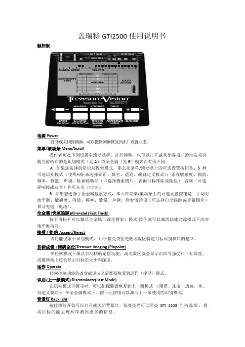
盖瑞特GTI2500使用说明书触控板电源Power打开或关闭探测器,可以把探测器恢复到出厂设置状态。
菜单/滚动条 Menu/Scroll操作者可在下列设置中滚动选择,进行调整,也可以打开或关闭各项。
滚动选项会随当前所在的是识别模式(见A)或全金属(见B)模式而有所不同。
A. 如果您选择的是识别搜索模式,那么在菜单/滚动条上的可选设置按钮是:5种可选识别模式(使用+或-来选择硬币、珠宝、遗迹、或自定义模式);还有敏感度、阀值、频率、数量、声调、检索辅助项(可选择搜索图片、表面目标排除或除盐);音频(可选择响铃或双音)和可充电(电池)。
B. 如果您选择了全金属搜索方式,那么在菜单/滚动条上的可选设置按钮是:手动对地平衡、敏感度、阀值、频率、数量、声调、检索辅助项(可选择自动跟踪或查询图片)和可充电(电池)。
全金属 (快速追踪)All-metal (Fast Track)按下再松开可以激活全金属(深度搜索)模式;按住就可以激活快速追踪模式下的对地平衡功能。
接受 / 拒绝 Accept/Reject该功能仅限于识别模式,用于接受或拒绝低读数区特定目标识别缺口的建立。
目标成像(精确定位)Treasure Imaging (Pinpoint)在任何模式下激活自动精确定位功能,高读数区就会显示出信号强度和目标深度,成像网格上还会显示目标的大小和深度。
运作 Operate任何控制功能的改变或调节之后都要恢复到运作(搜寻)模式。
识别 (上一级模式) Discraminate(Last Mode)在识别模式下搜寻时,可以把探测器恢复到上一级模式(硬币、珠宝、遗迹、零、自定义模式);在全金属模式下,按下此按钮可以激活上一级使用的识别模式。
背景灯 Backlight按住或放开就可以打开或关闭背景灯。
低度亮光可以照亮GTI 2500的液晶屏,提高目标的能见度和探测到更多的信息。
+ & -通过这些触控板可以对GTI 2500进行精确的调节。

FUT350数字超声波探伤仪使用说明书感谢您购买本产品,使用产品前请仔细阅读本使用说明书。
目录序言 .......................................................................................... - 4 -1 常规安全概述............................................................................ - 5 -2 数字超声波探伤仪简介 ............................................................. - 6 -2.1 功能及特点 ..................................................................... - 6 -2.2 主要性能参数.................................................................. - 7 -2.3 仪器面板及主要部件说明................................................ - 8 -2.4 按键说明........................................................................- 10 -2.5 仪器菜单流程及说明...................................................... - 11 -3 探伤仪的基本调节与应用.........................................................- 20 -3.1 仪器的开机及关机 .........................................................- 20 -3.2 闸门的调节 ....................................................................- 21 -3.3 增益的调节 ....................................................................- 23 -3.4 范围的调节 ....................................................................- 25 -3.5 移位的调节 ....................................................................- 26 -3.6 扩展功能........................................................................- 26 -3.7 仪器发射相关功能的调节...............................................- 27 -3.8 仪器接收相关功能的调节...............................................- 29 -3.9 探头参数调节.................................................................- 31 -3.10 仪器的显示特性...........................................................- 32 -4 仪器的校准及标定....................................................................- 34 -4.1 扫查的设置 ....................................................................- 34 -4.2 声速的标定 ....................................................................- 35 -4.3 直探头延时的标定 .........................................................- 36 -4.4 斜探头延时及前沿的标定...............................................- 38 -4.5 斜探头K值的标定.........................................................- 39 -5 仪器辅助功能及应用................................................................- 41 -5.1 DAC曲线的制作与应用..................................................- 41 -5.2 AVG曲线的制作与应用 ..................................................- 46 -5.3 包络功能........................................................................- 49 -5.4 波形扩展功能.................................................................- 50 -5.5 屏幕保护功能.................................................................- 51 -5.6 冻结及波形对比功能......................................................- 52 -5.7 连续存储功能.................................................................- 53 -6 数据处理..................................................................................- 55 -6.1 文字输入........................................................................- 55 -6.2 数据的存储 ....................................................................- 57 -6.3 数据的回放及删除 .........................................................- 58 -6.4 通道的使用 ....................................................................- 58 -6.5 报表的使用 ....................................................................- 59 -7 仪器的通讯及恢复出厂 ............................................................- 60 -7.1 系统信息........................................................................- 60 -7.2 恢复出厂设置.................................................................- 60 -7.3 主题设置........................................................................- 60 -7.4 数据通讯........................................................................- 60 -8 充电器及电池的使用说明.........................................................- 61 -8.1 供电电源........................................................................- 61 -8.2 电池充电........................................................................- 62 -9 仪器的保养与维修....................................................................- 63 -9.1仪器的日常维护..............................................................- 63 -9.2仪器故障及处理方法.......................................................- 63 -9.3 仪器维修........................................................................- 65 -10 仪器配套及选购件..................................................................- 65 -附录.............................................................................................- 67 -附录1通用探伤报表 ............................................................- 67 -附录2 常见问题解答 ...........................................................- 68 -附录3 超声波探伤仪计量检定说明......................................- 70 -附录4 菜单快速索引 ...........................................................- 71 -附录5 仪器操作流程图........................................................- 72 -用户须知 ................................................................................- 73 -序言感谢您使用我公司的超声波探伤仪产品,您能成为我们的用户,是我们莫大的荣幸。

eTrex Legend(中文)——传奇使用手册GPS新概念——真正的数字化生活中文输入功能完善超大内存面积计算人性化界面不得用于商业用途目录第一章:序言部分第二章:速查部分1.性能简介2.按键及功能介绍3.电池的安装4.显示屏背景光及对比度设置5.主页页面转换6.地图页面基本情况7.导航页面基本情况8.旅行计算机页面基本情况9.主菜单页面基本情况10.把当前位置标志为航路点11.改变航路点符号12.引导返回到您的起始点第三章:手册部分13.概述14.如何选择“关闭GPS”15.导航方式——概述16.地图页面概述17.地图页面选项概述18.使用移动光标概述19.停止导航20.数据区概述21.设置地图概述22.设置地图操作步骤23.导航页面概述24.设置导航页面操作步骤25.旅行计算机页面概述26.使用主菜单27.存点航路点页面概述28.创建航路点29.设计航路点不得用于商业用途30.查找菜单概述31.查找航路点概述32.查找操作步骤34.查找兴趣点概述37.创建和使用航线概述38.编辑航线39.编辑航路点40/41。
航线使用概述42.航线页面的数据区43.使用航迹概述44.航迹使用操作步骤45.设置页面概述46.单位页面概述47.显示页面概述48.接口页面概述49.系统页面概述50.工具概述51.日历概述52.打猎/捕鱼概述53.面积计算第四章:附录附录A:技术指标附录B:时差表附录C:配件附录D:数据接口附录E:简单故障维修不得用于商业用途第一章序言说明书介绍感谢您购买eTrex Legend(传奇)GPS接收机——我们不停努力的结果,为了可以使您的新型GPS接收机发挥最大的用途,并且了解所有的操作细节,您可以花些时间阅读一下本手册。
手册由四部分组成:一、序言部分二、速查部分介绍了一些Legend的细节、主要操作页面和基本导航方式三手册部分提供了使用Etrex Legend 的所有细节。
四、附录部分包括一些有关附件,说明书,维修向导,主题索引等方面的信息。

PRG 350 Series Stainless Steel Regulators***********************Servicing North America:U.S.A. Omega Engineering, Inc.Headquarters: Toll-Free: 1-800-826-6342 (USA & Canada only)Customer Service: 1-800-622-2378 (USA & Canada only)Engineering Service: 1-800-872-9436 (USA & Canada only)Tel: (203) 359-1660 Fax: (203) 359-7700**************e-mail:For Other Locations Visit /worldwideThe information contained in this document is believed to be correct, but OMEGA accepts no liability for any errors it contains, and reservesContentsSectionDescription Page 1.0Specifications 22.0Installation 23.0Operation 34.0Maintenance &Repair 35.0Warranty 5Stainless Steel RegulatorsInstallation,Operation andMaintenance Instructions350Bonnet Range Spring*Pintle Assembly*Housing Seal O-Ring *Filter O-Ring (2)Drip Well HousingAssemblyFilter Retainer Spring GuideAdjustment Screw Assembly*DiaphragmAssemblyBody AssemblyCollarFilter,25Micron,SS Filter Retaining ScrewPintle SpringPRG 350SS 1/2"NPT*Included with repair kitRefers to conditions or hazards which could result in serious personal injury or death.Refers to conditions or hazards which could result in personal injury.Refers to conditions or hazards which could result in equipment or property damage.Alerts you to facts or special instructions.ALL DANGER,WARNING,AND CAUTION NOTICES MUST BE COMPLIED WITH IN FULL Personal injury,property damage,equipment damage,or leakage due to escaping gas or bursting ofpressure containing parts may result if this regulator is over pressurized or installed where serviceconditions could exceed the limits given in the specifications.To avoid such injury or damage,providepressure-relieving or limiting devices(as required by the appropriate code,regulation or standard)toprevent service conditions from exceeding those limits.1.Output Ranges:0-30psig(0-2.0BAR),0-60psig(0-4.0BAR),0-100psig(0-7.0BAR),0-150psig(0-10.0BAR)Exhaust Capacity: 1.0SCFM(1.7m3/hr)at downstream pressure of10psig(0.7BAR)above set pointMaximumSupply Pressure:290psig(20.0BAR)Air Consumption:4SCFH(0.1m3/hr)OperatingTemperatures:-20°to+185°F(-29°to+85°C)Filter:25micronPorting:Inlet/Outlet:1/4"NPT or1/2"NPTGauge(2):1/4"NPTExhaust:1/8"NPTMaterials:316stainless steel:body,bonnet,filterFluorocarbon:diaphragm,sealsInconel:range spring,pintle springWeight:1/4"NPT:2.2lbs.(1.0kg)1/2"NPT:2.8lbs.(1.3kg)2.2.1Install the regulator/filter as close as possible to the instrument or tool it is to service.2.2Clean all pipelines to remove dirt and scale prior to installation.Failures attributable to air supply contamination are not covered by the warranty.This instrument vents to atmosphere.The use of gas other than air may create ahazardous environment.2.3Install the regulator/filter so that the direction of flow is from the"IN"to"OUT"connec-tion as marked on the body of the regulator/filter.2.4For best drainage,orient the drain valve so that it is at the lowest point on the drip wellhousing.Positioning of the drain valve may be improved by rotating the drip well with respect to the body.2.5The exhaust port should be kept free and unplugged.Position the regulator so that thevent is at the lowest point possible,or provide additional protection to prevent contami-nants from entering the regulator.Rotating the bonnet relative to the body may change the vent hole orientation.The PRG350Series has a low capacity internal relief that provides limited down stream protectionagainst over pressurization.2.6Exhaust may be remotely vented by installing tubing to the1/8"NPT port.2.7Apply pipe compound or sealing tape to the male pipe threads prior to installingregulator/e caution to prevent the sealant from getting inside the regulator/filter.3.3.1Prior to turning on supply air,back off adjusting screw until there is no compression ofthe range spring.3.2After applying the air supply,output pressure will be increased by rotating the adjust-ment screw clockwise.Pressure can be decreased by turning counter clockwise.3.3Tighten locknut to maintain desired pressure setting.4.4.1To remove condensate from the PRG350Series,slowly open drain valve by turningclockwise and bleed accumulated liquid.To avoid personal injury,property damage,or equipment damage caused by sudden release of pres-sure or explosion of accumulated gas,do not attempt any maintenance or disassembly without firstisolating the regulator from system pressure and relieving all internal pressure from the regulator. 4.2To clean filter element4.2.1Shut off supply pressure and relieve all internal pressure.4.2.2Drain condensate from drip well.4.2.3Remove four corner bolts from bottom of unit and remove drip well housing.4.2.4Remove filter retaining screw.4.2.5Remove filter retainer,filter o-ring seals and filter.4.2.6Clean parts and reassemble in reverse order.4.3To clean/replace pintle assembly4.3.1Follow steps4.2.1through4.2.4.4.3.2Unscrew collar and remove.4.3.3Remove pintle spring and pintle.1/4"NPT version may require needle nose pliers or push pintle stem from above byremoving bonnet and diaphragm assembly.4.3.4Clean/replace parts and reassemble in reverse order.4.4To clean/replace diaphragm assembly4.4.1Back out the adjusting screw until the spring is no longer compressed.4.4.2Remove the four bonnet screws and separate the bonnet from the body of the regulator.Remove the spring guideand spring.4.4.3Remove the diaphragm assembly,clean or replace it as necessary and reassemble in reverse order.After placing thediaphragm assembly on the body,push down the assembly to make sure that the pintle is seated properly andstrokes smoothly.4.5Repair kits/replacement parts4.5.1Repair kits include all parts marked with an asterisk(*).See diagrams on page1.4.5.2When ordering repair kits or replacement filters,order as:REPAIR KITSPRG350Includes:Pintle Assembly,Housing Seal O-Ring,Diaphragm Assembly,Filter Seal O-Ring(2)Model Porting Description Part NumberPRG3541/4”NPT Relieving449-871-068PRG3521/2”NPT Relieving449-871-0704.5.3Other replacement parts are available.Please consult Omega Engineering,Inc.for part numbers and availability.OMEGA’s policy is to make running changes, not model changes, whenever an improvement is possible. This affords our customers the latest in technology and engineering.OMEGA is a registered trademark of OMEGA ENGINEERING, INC.© Copyright 2016 OMEGA ENGINEERING, INC. All rights reserved. T his document may not be copied, photocopied, reproduced, translated, or reduced to any electronic medium or machine-readable form, in whole or in part, without the FOR WARRANTY RETURNS, please have thefollowing information available BEFORE contacting OMEGA:1. P urchase Order number under which the productwas PURCHASED,2. M odel and serial number of the product underwarranty, and3.Repair instructions and/or specific problems relative to the product.FOR NON-WARRANTY REPAIRS, consult OMEGA for current repair charges. Havethe following information available BEFORE contacting OMEGA:1.Purchase Order number to cover the COST of the repair,2.Model and serial number of the product, and 3.Repair instructions and/or specific problems relative to the product.RETURN REQUESTS/INQUIRIESDirect all warranty and repair requests/inquiries to the OMEGA Customer Service Department. BEFORE RET URNING ANY PRODUCT (S) T O OMEGA, PURCHASER MUST OBT AIN AN AUT HORIZED RET URN (AR) NUMBER FROM OMEGA’S CUST OMER SERVICE DEPART MENT (IN ORDER T O AVOID PROCESSING DELAYS). The assigned AR number should then be marked on the outside of the return package and on any correspondence.The purchaser is responsible for shipping charges, freight, insurance and proper packaging to prevent breakage in transit.WARRANTY/DISCLAIMEROMEGA ENGINEERING, INC. warrants this unit to be free of defects in materials and workmanship for a period of 13 months from date of purchase. OMEGA’s WARRANTY adds an additional one (1) month grace period to the normal one (1) year product warranty to cover handling and shipping time. This ensures that OMEGA’s customers receive maximum coverage on each product.If the unit malfunctions, it must be returned to the factory for evaluation. OMEGA’s Customer Service Department will issue an Authorized Return (AR) number immediately upon phone or written request. Upon examination by OMEGA, if the unit is found to be defective, it will be repaired or replaced at no charge. OMEGA’s WARRANT Y does not apply to defects resulting from any action of the purchaser, including but not limited to mishandling, improper interfacing, operation outside of design limits, improper repair, or unauthorized modification. T his WARRANT Y is VOID if the unit shows evidence of having been tampered with or shows evidence of having been damaged as a result of excessive corrosion; or current, heat, moisture or vibration; improper specification; misapplication; misuse or other operating conditions outside of OMEGA’s control. Components in which wear is not warranted, include but are not limited to contact points, fuses, and triacs.OMEGA is pleased to offer suggestions on the use of its various products. However, OMEGA neither assumes responsibility for any omissions or errors nor assumes liability for any damages that result from the use of its products in accordance with information provided by OMEGA, either verbal or written. OMEGA warrants only that the parts manufactured by the company will be as specified and free of defects. OMEGA MAKES NO OTHER WARRANTIES OR REPRESENTATIONS OF ANY KIND WHATSOEVER, EXPRESSED OR IMPLIED, EXCEPT THAT OF TITLE, AND ALL IMPLIED W ARRANTIES INCLUDING ANY W ARRANTY OF MERCHANTABILITY AND FITNESS FOR A PARTICULAR PURPOSE ARE HEREBY DISCLAIMED. LIMITATION OF LIABILITY: The remedies of purchaser set forth herein are exclusive, and the total liability of OMEGA with respect to this order, whether based on contract, warranty, negligence, indemnification, strict liability or otherwise, shall not exceed the purchase price of the component upon which liability is based. In no event shall OMEGA be liable for consequential, incidental or special damages.CONDITIONS: Equipment sold by OMEGA is not intended to be used, nor shall it be used: (1) as a “Basic Component” under 10 CFR 21 (NRC), used in or with any nuclear installation or activity; or (2) in medical applications or used on humans. Should any Product(s) be used in or with any nuclear installation or activity, medical application, used on humans, or misused in any way, OMEGA assumes no responsibility as set forth in our basic WARRANTY /DISCLAIMER language, and, additionally, purchaser will indemnify OMEGA and hold OMEGA harmless from any liability or damage whatsoever arising out of the use of theProduct(s) in such a manner.Where Do I Find Everything I Need for Process Measurement and Control?OMEGA…Of Course!Shop online at SMTEMPERATUREⅪߜThermocouple, RTD & Thermistor Probes, Connectors, Panels & AssembliesⅪߜWire: Thermocouple, RTD & ThermistorⅪߜCalibrators & Ice Point ReferencesⅪߜRecorders, Controllers & Process MonitorsⅪߜInfrared PyrometersPRESSURE, STRAIN AND FORCEⅪߜTransducers & Strain GagesⅪߜLoad Cells & Pressure GagesⅪߜDisplacement TransducersⅪߜInstrumentation & AccessoriesFLOW/LEVELⅪߜRotameters, Gas Mass Flowmeters & Flow ComputersⅪߜAir Velocity IndicatorsⅪߜTurbine/Paddlewheel SystemsⅪߜTotalizers & Batch ControllerspH/CONDUCTIVITYⅪߜpH Electrodes, Testers & AccessoriesⅪߜBenchtop/Laboratory MetersⅪߜControllers, Calibrators, Simulators & PumpsⅪߜIndustrial pH & Conductivity EquipmentDATA ACQUISITIONⅪߜCommunications-Based Acquisition SystemsⅪߜData Logging SystemsⅪߜWireless Sensors, Transmitters, & ReceiversⅪߜSignal ConditionersⅪߜData Acquisition SoftwareHEATERSⅪߜHeating CableⅪߜCartridge & Strip HeatersⅪߜImmersion & Band HeatersⅪߜFlexible HeatersⅪߜLaboratory HeatersENVIRONMENTALMONITORING AND CONTROLⅪߜMetering & Control InstrumentationⅪߜRefractometersⅪߜPumps & TubingⅪߜAir, Soil & Water MonitorsⅪߜIndustrial Water & Wastewater TreatmentⅪߜpH, Conductivity & Dissolved Oxygen Instruments。

PerfectCare AzurSteam 50g/min; 220g steam boostT-ionicGlide soleplate Safety Auto off + Anti-calc Safe for all ironable garmentsGC4929/86Fastest Philips steam iron* From jeans to silk in one goIron any ironable garment from jeans to silk, from linen to cashmere safely in one go; in any order without temperature adjustment. PerfectCare Azur delivers perfect results with no risk of burn or shine. Ironing is now easier and faster.Comfortable ironingInnovative CordGuideSuitable for tap water with Double Active Calc Clean systemT-ionicGlide: our best 5-star rated soleplateDeep ionised steam for optimal, hygienic ironingOne perfect setting for all your clothes100% easy to use, no adjustment required100% safe on all ironable garments100% fast on all fabrics; no other steam iron is fasterOptimalTemp technology: perfect combination of temperatureFast and powerful ironing3000 W iron for fast heat-upSteam output of up to 50 g/min for better crease removalSteam boost up to 220 gHighlights100% easy to use100% easy to use, no adjustment required. You can now iron all ironable garments one after the other, without having to wait or to adjust the iron's temperature dial.100% safe100% safe on all fabrics even the most delicate like silk, cashmere, wool, polyester.Independent iron testing institutes have used PerfectCare on the most sensitive ironable garments and they confirmed excellent ironing results.100% fast100% fast to iron, no sorting required. Iron all your garments with more effective steam.Steam boost up to 220 gThe steam boost can be used for vertical steaming and tough creases.Steam up to 50 g/minContinuous steam output of up to 50 g/min gives you the perfect amount of steam to efficiently remove all creases.CordGuideThe innovative CordGuide simply clicks onto your ironing board and guides the cord away while you iron.Suitable for tap waterPerfectCare Azur steam iron is designed to be used with tap water. Double Active Calc Clean:A smart combination of Calc Pills and a regular Self Clean reduce the scale built-up. For better ironing results we recommend to usedemineralised water. This ensures a consistent steam flow from your iron.T-ionicGlide soleplateT-ionicGlide is Philips' premium soleplate.Delivering a new standard in glide andscratch-resistance for OptimalTemp irons. The patented new coating will secure excellent results. The carefully designed shape and vent holes provide even steam distribution for easy crease removal with the steam iron.OptimalTemp technologyThe latest revolution in ironing to deliver the perfect combination of steam and temperature.It's made to ensure you get speedy ironing and great results on tough creases, with no setting required, and is safe on all ironable fabrics. The perfect combination of steam and temperature because: 1) the Smart Control Processor sets the right temperature 2) the HeatFlow technology enables an even steam and temperature balance.Deep ionised steamThe unique composition of ions automatically released into the steam results in optimal,hygienic ironing on all ironable garments.SpecificationsAccessoriesCordGuideFilling cupCalc managementCalc clean reminderCalc clean solution: Double active calc clean Suitable for tap waterEasy to useCord freedom (swivel): 180 degree cord freedomCord storage: Cord clip Drip-stopPower cord length: 2.5 mSafety auto offSoft gripWater tank capacity: 350 mlFilling and emptying water: Extra-large fillingholeFast and powerful crease removalContinuous steam output: 50 g/minOptimalTEMP technologyPower: 3000 WSoleplate: T-ionicGlideSpraySteam boost: 220 gSustainabilityEnergy saving*: 10 %User manual: 100% recycled paperWeight and dimensionsWeight of iron: 1.75 kg* compared to other Philips dry irons* Tested against Philips steam irons© 2019 Koninklijke Philips N.V.All Rights reserved.Specifications are subject to change without notice. Trademarks are the property of Koninklijke Philips N.V. or their respective owners.Issue date 2019‑09‑20 Version: 2.0.1EAN: 08 71010 37397 91 。

BackBeat FIT serie 350 Guida dell'utenteSommarioPanoramica dell'auricolare3Sicurezza3Installare l'app4Associazione5Procedura di associazione5Modalità di associazione5Ricarica e montaggio6Ricarica6Ricarica rapida6Regolazione6Predisposizione del dispositivo7Informazioni di base8Accensione o spegnimento8Regolare il volume8Musica e altro8Riconnessione8Risposta e termine di una chiamata8Ripetere l'ultimo numero8Esclusione del microfono8Caratteristiche della cuffia9Assistente vocale9Risposta alle chiamate da un secondo dispositivo9Comandi vocali9Modalità DeepSleep9Supporto10Porta di ricarica Potenza Spento Comandi di aumento del volume Ricerca traccia in avanti Esclusione microfono Riproduzione/Pausa Siri, Google Now ™Assistente vocale Associazione Bluetooth ®Tasto di risposta/fine chiamata Comandi di diminuzione del volume Ricerca della traccia indietro Prima di utilizzare l'auricolare, consultare il documento "Tutela della sicurezza" per importantiindicazioni relative alla sicurezza, alla ricarica, alla batteria e alle norme vigenti.Panoramica dell'auricolareSicurezzaInstallare l'appPer ottenere il massimo dall'auricolare, scaricare la nostra app gratuita, BackBeat per iOS/Android™.L'app consente di:•Attivazione/disattivazione della funzione•Find MyHeadset•Visualizzare la guida dell'utentePer prestazioni ottimali, installare l'app BackBeat su tutti i dispositivi associati all'auricolare.Alla prima accensione dell'auricolare, viene avviata la procedura di associazione.1Accendere la cuffia premendo il pulsante centrale fino a quando non viene emessa la richiestavocale di associazione e il LED non lampeggia rosso e blu.2® sul telefono e avviare la ricerca di nuovi dispositivi.•iPhone > Impostazioni > Bluetooth > On*•Android > Impostazioni > Bluetooth > On > Ricerca*NOTA *I menu possono variare a seconda del dispositivo.3Selezionare "PLT serie BBFIT350 ".Se richiesto, immettere quattro zeri (0000) come codice o accettare la connessione.Una volta completata l'associazione, viene emesso l'avviso vocale "pairing successful"(associazione riuscita) e l'indicatore luminoso smette di lampeggiare.Esistono due modi per impostare la modalità di associazione sull'auricolare. Scegliere:•Con l'auricolare acceso, tenere premuti i pulsanti di aumento (+) e riduzione (-) del volume fino a quando non viene emesso l'avviso vocale "Associazione".•Con l'auricolare spento, tenere premuto il pulsante centrale fino a quando non viene emesso l'avviso vocale "Associazione".NOTA È possibile collegare fino a 2 dispositivi all'auricolare.AssociazioneProcedura di associazioneModalità di associazioneLo sportello che copre la porta di ricarica si trova sul lato sinistro del controller in linea. Aprirlo aiutandosi con l'unghia. Per prestazioni ottimali, caricare completamente la batteria prima dell' ricarica completa degli auricolari può richiedere fino a 2 ore. Durante la carica, l'indicatore luminoso è rosso e si spegne una volta che la ricarica è completa.Una ricarica di 15 minuti dell'auricolare consente di ascoltare musica per un massimo di un'ora.Per ottenere un audio di ottima qualità, è essenziale una corretta aderenza al canale auditivo.Provare i copriauricolari in tre diverse dimensioni per trovare quello più adatto. Per una miglioreaderenza, è possibile utilizzare copriauricolari di dimensioni diverse da un orecchio all'altro.L'incavo del copriauricolare destro è più grande del copriauricolare sinistro.1Prova del copriauricolare Inserire gli auricolari nelle orecchie e assicurarsi che il supporto perorecchio sia saldamente posizionato nell'orecchio per una migliore stabilità.scegliere quello più comodo che offre l'audio migliore.2Rimozione del copriauricolare Per rimuovere il copriauricolare, tirarlo con decisione.3Sostituzione del copriauricolare Premere il copriauricolare nel cuscinetto contrassegnato con "L" o "R" con l'incavo sul copriauricolare di gomma verso l'alto e l'incavo in plastica sollevato nelcuscinetto.Ricarica e montaggioRicaricaRicarica rapidaRegolazione4Pulizia del copriauricolare Quando è necessario, pulire i copriauricolari con una salvietta imbevuta di alcol o un batuffolo di cotone immerso in alcool isopropilico.Esistono 2 modi per utilizzare la clip fermacavetto al fine di rendere stabile l'auricolare.•FissaggioPassare il cavo dell'auricolare dietro al collo e fissare la clip all'abito indossato.•Regolazione della lunghezzaAccorciare il cavo in eccesso con la clip.Predisposizione del dispositivoPer accendere il dispositivo, premere il pulsante centrale per 2 secondi fino a quando non viene emesso l'avviso vocale "Acceso". Per spegnere il dispositivo, premere il pulsante centrale per 4secondi fino a quando non viene emesso l'avviso vocale "Spento".Premi il tasto (+) o (-) per aumentare o diminuire il volume.Ascoltate la musica, i podcast, le indicazioni di navigazione e altro audio in streaming sul dispositivo.NOTA La funzionalità varia in base all'applicazione.Riproduzione o pausa dell'audio Toccare il pulsante centrale.Passaggio al brano successivo Premere per 2 secondi il pulsante di aumento (+) del volume.Riproduzione del brano precedente Premere il pulsante di riduzione del volume fino a quando non viene emesso il tono di conferma per ricominciare il brano corrente. Premere due volte il pulsante (bisogna quindi attendere l'emissione di due toni di conferma successivi) per andare alla traccia precedente.Se l'auricolare perde il collegamento Bluetooth con il telefono in uso, tenta automaticamente di ristabilirlo.In caso di esito negativo, toccare una volta qualsiasi tasto o stabilire la connessione manualmente tramite il Bluetooth del telefono. Se l'auricolare rimane fuori dal raggio d'azione per più di 90minuti, si attiva la modalità DeepSleep.Toccare il pulsante centrale.Toccare due volte il pulsante centrale per chiamare l'ultimo numero composto.Durante una conversazione, tenere premuto i pulsanti di aumento e riduzione del volume finchénon viene emesso l'avviso vocale di attivazione o disattivazione dell'esclusione microfono. Quando l'esclusione microfono è attiva, viene ripetuto un avviso ogni 15 minuti.Informazioni di baseAccensione o spegnimentoRegolare il volumeMusica e altroRiconnessioneRisposta e termine di una chiamataRipetere l'ultimo numeroEsclusione del microfonoSiri, Google Now ™, Cortana Tenere premuto il pulsante centrale per 2 secondi finché non viene emesso il tono. Attendere la richiesta del telefono per attivare la selezione vocale, la ricerca e altri controlli vocali dello smartphone.Rispondere alle chiamate da due dispositivi è facile.Mentre è in corso una chiamata, il secondo dispositivo associato emette una notifica sonora per la chiamata in arrivo.Per rispondere a una seconda chiamata dall'altro dispositivo, toccare innanzitutto il pulsante centrale per terminare la chiamata in corso, quindi toccare nuovamente lo stesso pulsante per rispondere alla nuova chiamata. Se si sceglie di non rispondere alla seconda chiamata, questa viene trasferita alla segreteria.Il dispositivo emette avvisi vocali che informano circa le variazioni di stato. Ad esempio:"Power on" (Acceso)"Pairing successful" (Associazione riuscita)"Phone 1 connected" (Telefono 1 collegato)"Nessun telefono è collegato""Mute on" (Esclusione microfono attivata)Se gli auricolari vengono lasciati accesi ma fuori dal raggio d'azione del telefono a cui sonoassociati per 90 minuti, preservano la carica della batteria passando in modalità DeepSleep.Una volta che il dispositivo ritorna entro il raggio d'azione del cellulare, premere il pulsante centrale per uscire dalla modalità DeepSleep.Caratteristiche della cuffiaAssistente vocaleRisposta alle chiamate da un secondo dispositivoComandi vocaliModalità DeepSleepSupportoULTERIORI INFORMAZIONI/supportPlantronics, Inc.Plantronics B.V.345 Encinal Street Santa Cruz, CA 95060 United States Scorpius 171 2132 LR Hoofddorp Netherlands© 2018Plantronics, Inc. Bluetooth è un marchio registrato di Bluetooth SIG, Inc. e il suo uso da parte di Plantronics è concesso su licenza. Apple e Siri sono marchi di Apple, Inc., registrati negli Stati Uniti e in altri paesi. Tutti gli altri marchi sono di proprietà dei rispettivi proprietari.Brevetti in attesa di approvazione.213118-16 (12.18)。

目录本产品在出厂时,性能完好,包装完整。
所有使用者应严格遵守本用户手册所述的警告事项和操作说明,任何因误用而导致的损坏,不在本公司保障之内,对忽视用户手册而导致的故障和问题亦不在经销商负责的范围内。
本用户手册内相关内容资料仅供参考,所有灯具产品均以实物为准,如有变动,恕不另行通知,本司将保留最终解释权。
一、安全警告信息 (1)二、技术参数 (2)三、安装标准 (3)四、显示屏控制说明 (7)五、错误信息 (10)六、通道控制说明 (11)七、产品保养 (15)一、安全警告信息1.注意!由于灯具的光学系统会聚焦太阳光至灯体内部,导致内部部件损坏或引起火灾。
请注意在任何时候都需要确保太阳不会直射到灯具顶部的透镜上。
2.收到产品后,请拆开包装检查,确保灯具没有因运输而造成的损坏。
3.本产品只适用于专业用途,请确保本产品由专业人士安装和操作。
非专业人员,切勿私自拆机检查和维修。
4.本产品适用的环境温度范围是-5℃-45℃,请勿在过高或过低的环境中使用。
5.本产品必须安装在通风良好处,并确保产品通风孔通畅,以免产品运行时过热。
6.安装前,请确保电源电压符合灯具所标识的电源电压,且要有过载或者漏电保护。
7.安装时,请确保本产品和邻近物体至少保持0.5米的距离8.安装时,请确保本产品正确接地,并按照相关标准进行电器安装,以防电击。
9.悬挂本产品时,须确保设施及灯钩能承受至少本产品的10倍重量,并使用安全绳作为辅助安全方式固定好产品。
必须确保安全绳有效连接。
10.当产品在运行或接上电源时,请确保产品远离易燃易爆物品,产品距易燃易爆物品的最短距离为0.5米。
11.请确保产品使用规定型号的保险丝。
12.无论任何时候,请避免易燃物、水、金属、等异物进入灯具内部,以免引起电击或起火。
如有异物进入灯具,请立即切断电源。
13.由于产品运行时表面温度较高,并且产品有较多转动部件,请勿在产品运行时触摸。
14.本产品应在10米之后投射物体,避免近距离投射物体,以免引起火灾。

Maintenance ManualGeneralThe following operation- and maintenance manual is valid for Y -S t r a i n e r s , s e r i e s 350. At correct assembly, maintenance and repair we guarantee a trouble- free function. If the operation- and maintenance manual is not followed correctly, the manufacturer is not responsible for the efficiency and safety of the valves.The strainers must not be operated above the limits and rules indicated in the different documents (e.g. operation rules, purchase documents, datasheets). Operation above the indicated limitations can damage the strainers and finally destroy them. The descriptions and rules indicated in this operation- and maintenance manual refer to standard types, but apply at the same time for special designs and related constructions.This operation instruction does not consider:- any possible accidents and interruptions which could arise by wrong assembly, operation or commissioning of the strainers.- any safety rules in relation to the place where the s t r a i n e r is installed.The operator is responsible for the observation of the safety rules, also for the assembly staff.The operation- and maintenance instructions for all other devices or parts of the plant linked to the strainers have to be considered and checked, but is not subject in this manual.This operation- and maintenance manual contains important information for the correct installation, operation, maintenance and commissioning of the designated valves.This has to be read by qualified personnel and considered prior installation and operation of the plant. Not only the general safety instructions must be observed, but also all other rules and regulations in the following chapters.Remarks to the operation manualThe safety instructions of this operation manual act to avoid any accident or injuries to persons.Dangers which can result if safety instructions are not observedIf the safety instructions are not observed, persons, environment and t h e valve itself can be damaged. Possibly the indemnity rights get lost.The non-observance of the safety instructions can cause dangers, e.g.: - Break down of important functions of the valve or the unit - Failure of prescribed methods of commissioning and handling- Danger to persons caused by electrical, mechanical and chemical impacts - Damage to the environment caused by a leakageA non- observance of this warning can cause injuries to persons and defects of the machines, e.g.:Injuries caused by leaking valves (e.g. cold/hot, toxic, media content…)Improper use of the product characteristics during operation can permanently disturb the strainers or even become unusable;Working with safety consciousnessThe safety instructions included in this document are following the national regulations for prevention of accidents. Further rules for the avoidance of accidents during operation as well as the compliance with work protection rules have to be considered and assured by the operator.Safety instructions for the operator / userWhenever some hot or cold valve parts could be touched, it may cause injuries.It must be assured that the parts are constructed in a way that they are protected from contacts. -The contact protection for moving parts (e.g. coupling) must not be taken during operation. - Leakage (e.g. at stem, at gaskets) of dangerous m e d i a s (explosive, toxic, hot) has to be removed in a way that no danger to persons or environment is given. Trouble- shooting must be started and failure has to be solved.- Injuries by electrical energy have to be excluded (please consider the details of this subject in the local guidelines for the power supply companies).Valves for higher or lower temperatures (> 50 ° C or <0 ° C) are to be protected against unintended contact (warning sign.Safety instructions for assembly, commissioning and maintenanceIt must be secured that all assembly, commissioning and maintenance work is done by skilled staff under consideration of this operation- and maintenance manual.Generally, any work at the strainer is only allowed if the valve is cooled down and pressure-less. Additionally the evaporation temperature of the media must be lower than the temperature of all wetted parts of the strainer.The opening of the valve under pressure can be deadly!Generally, any kind of work at the valves can only be done during plant shut-down. V alves which get in touch with health injuring media have to be decontaminated. Immediately after the work is done, all safety and protection devices have to be put in plac e again. P r i o r putting the valve intooperation again, the r u l e s o f t h e c h a p t e r “S t a r t - u p / C o m m i s s i o n i n g ” h a v e t o b e c o n s i d e r e d a n d f o l l o w e d.Re- assembly and source of spare partsAny modification of the valves has to be accepted and agreed by the manufacturer. The use of original spare parts and accessories which are authorized by the manufacturer supports the function and safety. If any damage is caused by using other parts the indemnity and warranty can be refused.Applicable rangeThe described strainers in this manual include the following versions: Sizes: DN15 up to DN250 (1/2“ bis 10“) Nominal pressure: PN16 and PN40Note the type designation at the nameplate!Intended usageStrainers are protecting the following equipment parts and devices against pollution. The efficiency depends on the used mesh- size. The strainers consist of a Y-type body and a cover for the screen.Inadmissible dutySafe operation is only guaranteed if the valve is mounted and used under the general regulations of these operating rules . The technical limits are shown in the technical documentation and must not be exceeded. Additionally the limitations are mentioned below:Operating conditionsBody material DIN 1.0619 /WCB -30°C up to +300°C Body material DIN 1.4408/1.4435 /CF8M -196°C up to +400°CIt is important to note that the strainers made of body material of 1.0619 / WCB should not used with aggressive and corrosive medias.OperationStrainers do not need special operation rules. The screen has to be cleaned periodically. (refer to chapter …Maintenance“).CommissioningStrainers do not need special instructions for commissioning. Air bubbles in the body should be removed (venting).DeliveryThe strainers are delivered ready for operation.Flanges are protected against mechanical damage with flange caps.During transport, make sure that the valves retain their mechanical protection by the flange caps. The transport must take place with suitable transport boxes (e.g. wooden boxes). The strainers must be secured in the transport boxes against crushing and tilting. Otherwise the valves may be damaged.Aids for lifting and transport in the plant have to be installed always directly on the body of the valve. Preferably, the transport should be done in horizontal position. Head protection is mandatory! W R O N G C O R R E C TDescription / DimensionsMeasurementStorageThe connections must be covered to prevent the penetration of dirt and dust (preferably with thedelivered flange caps). The strainers have to be stored dry and well ventilated. For long-term storage, the strainers must be checked and cleaned periodically. Machined surfaces must be protected by appropriate aids against corrosion.The strainers must be protected against influences of weather and environment.Corrosion protection Carbon steel valvesV alves made of un- alloyed or low- alloyed cast steel are c o a t e d with a primer and a2-components epoxy resin coating. The minimum film thickness is 50 μm. The trim parts as well as the inner surfaces are free of paint and coated with a temporary corrosion protection (e.g. oil) only. Machined flange facings have to be protected against outside influences with flange caps.Stainless steel valvesV alves made of stainless steel will be delivered without any coating.Mounting and maintenanceGeneral mounting instructionsPrior mounting/revision, all affected devices, machines and/or plant parts must be shut- off. If needed, disconnect the devices, machines and/or plant parts. Check the real shut- off prior the work starts!Put warning signs in place in order to avoid unintended commissioning of the devices , machines and/or plant parts.For the installation in horizontal steam pipes the Strainer should be installed side lying with the screen body for preventing water pockets.Valves for oxygen applications are additionally marked with "free of oil and grease, and suitable for oxygen". It is necessary to provide sufficient space for a screen replacement.Installation in the pipe, mounting with Flange connection1. Prior installation, the pipe must be cleaned;2. If necessary, strainers must be cleaned from dirt and dust;3. During installation in the pipeline, flanges of the pipeline must be exactly parallel to flange connections of the strainer. In addition the direction-arrow must show into flow direction.The strainer must be installed with cover shown downward (exception steam pipes, see chapter « General mounting instructions »).4. Flange connection screws are tightened with a torque spanner (Torques acc. EN921-934 Or ISO4732, 4032, 4017…) Tighten the screws in a crosswise sequence.5. Please consider that the strainer is mounted in a released condition;6. At standard installation (horizontal pipeline) the cover for the screen replacement shows downward. If the strainer is installed in a vertical pipeline with flow direction from bottom up cover shows up acc. to the direction- arrow. In this case, the dirt particles are not collected, but hold off.The flange sealings are to be centered correctly.Please use allowed materials for the screws and nuts only.For a correct flange connection, please use all the flange holes for the assembly.The permitted pressure must not be exceeded!For a new installation or even after a maintenance all pipes have to be flushed and cleaned. Dirt, welding beads and other dirt particles could result in a malfunction, but at least result in a less powerful strainer.Installation in the pipe, mounting with welded connection1. All installation instructions for mounting with flange connections are also applicable for weldedconnections.2. The welding of the connections with the pipeline connections must comply with the applicableguidelines.3. The safety requirements of the welding process depend on the place and situation of thewelding location.4. The welding process has to be carried out according the valid accident and fire protectionguidelines.5. Prior welding, we recommend to open the cover and remove the screen.6. The Flow direction have to be checked.7. Please use a new cover sealing for the assembly of the strainer. After assembly the strainerhas to be checked and tested for tightness.8. Prior final mounting in the pipeline strainer has to be cooled down.Dismantling the coverThe valve must be cooled down and pressure- less! Opening the valve under pressure can be deadly! Head protection and protection glasses are mandatory!The strainer must be cleaned prior dismantling the cover in case of application with dangerous media (e.g. toxic, caustic)Loosen the cover by using a spannerRemove carefully the cover, the cover sealing and the screen.Assembly the cover1. Prior assembly of the cover, the valve body has to be cooled down2. Use a new cover sealing!3. Put the screen into the body in a released condition and put the cover on it.4. It is important that the cover sealing is centered correctly and free of any kind of dirt.5.Subsequently, please tighten the screws in a crosswise sequence acc. to the applicable technical guidelines.6. Please check the tightness of the strainer.Maintenance (Cleaning of the screen)1. If the screen is dirty, it must be cleaned;2. Prior disassembly of the strainer, a replacement sealing must be available;3. Remove the cover by loosen the cover screws and take out the screen;4. Screen has to be cleaned (with cleanser);5. After cleaning, the screen can be dried with compressed air;6. The cleaning interval depends on the degree of pollution within the pipeline.7. Please check the screen and the cover sealing on any damages prior assembly;8. If necessary, damaged parts have to be replaced;9. At assembly, put the new cover sealing into the body.Take care that the cover sealing is clean and has no damage;10. Screen must be installed in a released condition. Put the cover on the body11. Please tighten the screws and nuts till the tightness is achieved.Please consider the common rules and guidelines of pipe- engineering ( e.g. torques) 11. Please tighten the screws and nuts acc. to the torques acc. EN 921-934or ISO4732, 4032, 4017…)12. Please check tightness on the final assembled strainerWarrantyOur general terms and conditions are valid.If these are not available, it can be requested at Zuercher Technik AGor downloaded from 。

SPRING ASSIST RAMP DOORSTEPSSTEPSO H CO H CREFERMICROOHC S H O W E RS T E PS T E P P A N T R YP A T I O D O O R13’L C D T V M O U N TPASS-THRU STORAGEPASS-THRU STORAGEO H CNIGHT STANDWARDKING BEDOPTIONAL ELECTRIC BEDAND PASS-THRU DINETTEDINETTEOPT.CHAIRPASS-THRU STORAGEPASS-THRU STORAGEREFERMICROOHCO H COHCS H O W E RS T E PS T E P S T O R A G EL C D T V M O U N TO H CNIGHT STANDWARDKING BEDOPT. ROLL-OVERSOFAOHC CLOSETSPRING ASSIST RAMP DOORSTEPS16’OPTIONAL ELECTRIC BEDAND PASS-THRU DINETTEOPT.CHAIROUTSIDE STORAGESTEPSSTEPSREFERQUEEN BEDWARDWARDO H COHCL C D T V M O U N TL C D T V M O U N TDINETTE3SPRING ASSIST RAMP DOORFREE STANDING TABLESTANDARD ROLL-OVER SOFASTANDARD ROLL-OVER SOFA12’6”TUB/SHOWERSTEPSMICROOHCREFERE N T . CE N T E R OPT.CHAIROPT.CHAIRS H O W E RQUEEN BEDWARDWARDOUTSIDE STORAGEO H C 7’3”14’6”74”OHCSPRING ASSIST RAMP DOORFREE STANDING TABLESTANDARD ROLL-OVER SOFASTANDARD ROLL-OVER SOFASTEPSFULL BEDSPRING ASSIST RAMP DOOROHCOPT.CHAIRREFERTUBLINENMICRO14’6”7’3”12’6”74”54”OHCFREE STANDING TABLESTANDARD ROLL-OVER SOFASTANDARD ROLL-OVER SOFATRAVEL TRAILERSTUB/SHOWERT V M O U N TE N T . C E N T E RQUEEN BEDOHCWARDWARDREFERO H CT V M O U N TPANTRYOHCSTEPSSTEPS12’6”SPRING ASSIST RAMP DOOROUTSIDE STORAGEOHCOPTIONAL ELECTRIC BEDAND PASS-THRU DINETTEDINETTEFIFTH WHEELS36DSX1327QB29QBS20CB33RZR1631QBThis optional three recliner sofa is available on 29QBS, 31QB and 36DSX133-RECLINER SOFA OPT.INTERIOR STANDARDSn 6 Gallon Gas/Electric DSI Water Heater n USB Charging Stationn Bluetooth Dual Zone AM/FM/CD/DVD Player n 8 Cu. Ft. Gas/Electric Refrigeratorn 35,000 BTU Forced Air Ducted Furnace n Ducted Air Conditioningn Wardrobe Cabinets in Bedroom n Porcelain Foot Flush Toilet n Plywood Decking n Full Height Ceilingn Real Wood Doors and Drawers n Free Standing Dinette Tablen Full Extension Kitchen Drawers (2)n Deep Single Bowl Kitchen Sink n Brushed Nickel Hardware n Skylight Over BathEXTERIOR STANDARDS n 13,500 BTU Air Conditioner n 102" Wide Body Construction n Radius Main Entry Door n Enclosed Tanksn Seamless EPDM Rubber Roof n Powder Coated I-Beam Chassis n Marine Grade External Speakers n Self Adjusting Brakes n Radial TiresREV PACKAGEn Decorative Vinyl Flooringn LED Low Profile Lighting Throughout n LED Lighted Accents n Convection Microwaven Drop-In 3 Burner Cook Top with Glass Covern Wood Blinds (Living area)n 12V Battery Disconnect n 2500# Tie Down Strapsn High Rise Pull-out Kitchen Faucet n Bathroom Fantastic Vent Fan n 30 Amp Service (TT)n 50 Amp Service (FW)n Friction Hinge Entry Doorn Oversized Swing Arm Grab Handle On Entry Door n LED Lighting n LED Ramp Lightn 30 Gallon Fuel Stationn External Fuel Cell with 12V Pump n Adjustable Powered Awning with LED Lighting n Generator Prepn External Shower with Hot & Cold Water n Solar Prep & Wiring n Satellite Prep & Wiring n Rear Back Up Camera Prepn Outdoor Grill Quick Connect n Outdoor TV Bracket & Hook Ups n Power Tongue Jack (TT)nSpare TirePOPULAR OPTIONSn 15,000 BTU Air Conditioner IPO 13,500BTU Air Conditioner n Second Air Conditioner n 4.0 Onan Generator (TT)n 5.5 Onan Generator (FW)n Gas/Oil Resistant Industrial TPO Flooring In Cargo Area n Large LED TV n Euro Chairn Happi-jac Bed Lift System n Ramp Door Patio Systemn Removable Rear Room Edge Carpet n Screen Wall/Tent Wall n 12V Heated Holding Tanksn Glass Neo Angle Shower Enclosure (27QB only)n High Gloss Fiberglass Sidewalls n 15K Air Conditioner n Screen Wall/Tent Walln Electric Bed with Max Clearance Pass-thru Dinette n 100 Gal. Fresh Water n Sofa Slide IPO Dinette (29QBS, 31QB, 36DSX13)STANDARDS & OPTIONSGVWR (Gross Vehicle Weight Rating) -is the maximum permissible weight of the unit when fully loaded. It includes all weights, inclusive of all fluids, cargo, optional equipment and accessories. For safety and product performance do NOT exceed the GVWR.GAWR (Gross Axle Weight Rating) -is the maximum permissible weight, including cargo, fluids, optional equipment and accessories that can be safely supported by a combination of all axles.UVW (Unloaded Vehicle Weight)* -is the typical weight of the unit as manufactured at the factory. It includes all weight at the unit’s axle(s) and tongue or pin and LP Gas. The UVW does not include cargo, fresh potable water, additional optional equipment or dealer installed accessories.CCC (Cargo Carrying Capacity)** -is the amount of weight available for fresh potable water, cargo, additional optional equipment and accessories. CCC is equal to GVWR minus UVW.Available CCC should accommodate fresh potable water (8.3 lbs. per gallon). Before filling the fresh water tank, empty the black and gray tanks to provide for more cargo capacity.*Estimated Average based on standard build optional equipment. **Estimated average based on standard build optional equipment.Each Forest River RV is weighed at the manufacturing facility prior to shipping. A label identifying the unloaded vehicle weight of the actual unit and the cargo carrying capacity is applied to every Forest River RV prior to leaving our facilities.The load capacity of your unit is designated by weight, not by volume, so you cannot necessarily use all available space when loading your unit.XLR Boost by Forest River2421 Century Drive n Goshen, IN 46528n E-mail:**************************Phone: 574-642-0438 n /XLR n #XLRtoyhaulersActual towing capacity is dependent on your particular loading and towing circumstances, which includes GVWR, GAWR and GCWR, as well as adequate trailer brakes. Please refer to the Owners Manual of your vehicle for further information. All information contained in this brochure is believed to be accurate at the time of publication. However, during the model year, it may be necessary to make revisions and Forest River, Inc., reserves the right to make all such changes without notice, including prices, colors, materials, equipment and specifications as well as the addition of new models and the discontinuance of models shown in this brochure. Therefore, please consult with your Forest River dealer and confirm the existence of any materials, design or specificationsthat are material to your purchase decision. ©2016 XLR, a Division of Forest River, Inc., a Berkshire Hathaway company. All Rights Reserved. 1/17BOOST Travel Trailers Fifth WheelsModel 20CB 27QB 29QBS 31QB 33RZR16 36DSX13Dry Hitch Weight 853-lbs. 1082-lbs. 1257-lbs. 1465-lbs. 1951-lbs. 2333-lbs.Unloaded Vehicle Weight 4955-lbs. 6385-lbs. 8100-lbs. 9320-lbs. 8558-lbs. 10046-lbs.Cargo Carrying Capacity 2898-lbs. 3600-lbs. 3317-lbs. 4145-lbs. 4999-lbs. 4287-lbs.Exterior Length 25’-0’’ 31’-0’’ 36’-10’’ 39’-3’’ 33’-2’’ 38’-8’’Exterior Height w/ AC 12’-5’’ 12’-5’’ 12’-5’’ 12’-5’’ 13’-5’’ 13’-5’’Exterior Width 102’’ 102’’ 102’’ 102’’ 102’’ 102’’Garage Length 14’-6” 14’-6” 12’-6” 12’-6” 16’ 13’Grey Capacity 38-Gal. 38-Gal. 38-Gal. 38-Gal. 38-Gal. 38-Gal.Black Capacity 38-Gal. 38-Gal. 38-Gal. 76-Gal. 38-Gal. 76-Gal.Fresh Capacity 50-Gal. 50-Gal. 50-Gal. 50-Gal. 100-Gal. 100-Gal.Awning 15’ 15’ 15’ 15’ 15’ 21’。

BackBeat FIT 350-Serie BedienungsanleitungInhaltHeadset-Überblick3Sicherheit geht vor!3App installieren4Paaren5Paarung5Paarungsmodus5Laden und Anpassen6Laden6Schnellladefunktion6Anpassung6Tragen des Headsets7Grundlagen8Ein- oder ausschalten8Lautstärke einstellen8Musik und mehr8Erneut verbinden8Annehmen und Beenden von Anrufen8Wahlwiederholung8Headset stummschalten8Merkmale des Headsets9Sprachassistent9Anrufe von einem zweiten Gerät annehmen9Sprachansagen9DeepSleep-Modus9Support10Anschluss für das Ladegerät Lautstärke Ausschalten Lauter Titel vor Stummschalten Wiedergabe/Pause Siri, Google Now ™Sprachassistent Bluetooth ®-Paarung Anruf annehmen oder beenden Leiser Titel zurück Bitte lesen Sie die Sicherheitsbestimmungen mit wichtigen Informationen zu Sicherheit,Aufladung, Akku und gesetzlichen Bestimmungen, bevor Sie das Headset in Betrieb nehmen.Headset-ÜberblickSicherheit geht vor!App installierenSchöpfen Sie das Potenzial Ihres Headsets mit unserer kostenlosen App BackBeat für iOS/Android™ voll aus.Mit dieser App haben Sie die folgenden Möglichkeiten:•Funktionen ein-/ausschalten•Find MyHeadset•Anzeigen des BenutzerhandbuchsFür eine optimale Nutzung sollten Sie die BackBeat-App auf allen Geräten installieren, die mitdem Headset gepaart sind.Beim erstmaligen Einschalten Ihres Headset wird der Paarungsprozess eingeleitet.1Schalten Sie das Headset ein, indem Sie die Mitteltaste drücken, bis Sie …Pairing“ (Paaren) hörenund die LED 2® und suchen Sie darüber nach neuen Geräten.•iPhone > Einstellungen > Bluetooth > Ein*•Android > Einstellungen > Bluetooth > Ein > Scan*HINWEIS *Menü kann je nach Gerät unterschiedlich aufgebaut sein.3Wählen Sie …PLT BBFIT350-Serie “.Geben Sie wenn nötig viermal die Null (0000) als Passkey ein oder akzeptieren Sie die Verbindung.Nach erfolgreicher Paarung hören Sie …Pairing successful“ (Paarung erfolgreich) und die Leuchtanzeige hört auf zu blinken.Sie können Ihr Headset auf zwei Arten in den Paarungsmodus versetzen. Folgende Möglichkeitenstehen zur Auswahl:•Halten Sie bei eingeschaltetem Headset die Tasten für die Lautstärkeregelung (+) bzw. (-) gedrückt,bis Sie …Paarung“ hören.•Halten Sie bei ausgeschaltetem Headset die Mitteltaste gedrückt, bis Sie …Paarung“ hören.HINWEIS Sie können bis zu 2 Geräte mit Ihrem Headset paaren.PaarenPaarungPaarungsmodusDie Klappe über dem Ladeanschluss befindet sich auf der linken Seite der Inline-Steuerung.Öffnen Sie sie mit Ihrem Fingernagel. Laden Sie für optimale Leistung Ihren Akku vor der Nutzung vollständig auf.Es dauert bis zu 2 Stunden, bis die Kopfhörer bei vollständig entladenem Akku komplett geladen sind. Beim Laden ist die Leuchtanzeige rot. Wenn der Ladevorgang abgeschlossen ist, schaltet sich die Leuchtanzeige den Sie Ihr Headset 15 Minuten lang auf und genießen Sie eine volle Stunde Musik.Für eine optimale Klangqualität ist ein guter Sitz im Gehörgang wichtig. Probieren Sie die dreiOhrstöpsel in unterschiedlichen Größen an, um herauszufinden, welche Ihnen am besten passen.Eventuell sind auch unterschiedlich große Ohrstöpsel für jedes Ohr für Sie optimal. Die Kerbe aufdem rechten Ohrstöpsel ist größer als die auf dem linken.1Testen Stecken Sie die Ohrhörer in die Ohren und stellen Sie sicher, dass der Stabilisierungsbügelsicher im Ohr sitzt und einen stabilen Sitz gewährleistet.2Abnehmen des Ohrstöpsels Ziehen Sie den Ohrstöpsel zum Abnehmen mit ein wenig Kraft heraus.3Austauschen des Ohrstöpsels Drücken Sie den Ohrstöpsel auf die Spitze des Ohrhörers mit der Markierung …L“ oder …R“. Achten Sie dabei darauf, dass die Kerbe auf dem Ohrstöpsel auf dieerhabene Kunststoffkerbe an der Spitze des Ohrhörers ausgerichtet ist.Laden und AnpassenLadenSchnellladefunktionAnpassung4Reinigen der Ohrstöpsel Reinigen Sie die Ohrstöpsel bei Bedarf mit einem alkoholhaltigen Tuch oder einem in Isopropylalkohol getränkten Wattestäbchen.Es gibt zwei Möglichkeiten, Ihr Headset mit dem Kleiderclip zu stabilisieren.•Anbringen Legen Sie die Schnur des Headsets um Ihren Nacken und befestigen Sie den Clip anIhrer Kleidung.•KürzenSichern Sie das überschüssige Kabel mit dem Clip.Tragen des HeadsetsUm das Gerät einzuschalten, halten Sie die Mitteltaste 2 Sekunden lang gedrückt, bis Sie …Einschalten“ hören. Um das Gerät auszuschalten, halten Sie die Mitteltaste 4 Sekunden lang gedrückt, bis Sie …Ausschalten“ hören.Drücken Sie die Lautstärketaste nach oben (+) oder unten (–).Hören Sie Musik, Podcasts, Navigationshinweise und andere Audio-Streams über Ihr Headset.HINWEIS Funktionen können je nach Anwendung variieren.Audio wiedergeben oder anhalten Tippen Sie auf die Mitteltaste.Zum nächsten Titel springen Halten Sie die Lautstärketaste (+) 2 Sekunden lang gedrückt.Vorherigen Titel abspielen Drücken Sie die Taste zum Verringern der Lautstärke, bis Sie den Bestätigungston zum erneuten Starten des aktuellen Titels hören. Drücken Sie die Taste zweimal, (jedes Mal drücken, bis der Bestätigungston erklingt) um zum nächsten Titel zu springen.Wenn Ihr Headset die Bluetooth-Verbindung zu Ihrem Telefon verliert, versucht es automatisch,die Verbindung wiederherzustellen.Wenn Ihr Headset die Verbindung nicht wiederherstellen kann, tippen Sie einmal auf eine beliebige Taste oder stellen Sie die Verbindung manuell über das Bluetooth-Menü des Telefons her. Wenn Ihr Headset sich länger als 90 Minuten außer Reichweite befindet, wird der DeepSleep-Modus aktiviert.Drücken Sie die Mitteltaste .Tippen Sie zweimal auf die Mitteltaste , um die zuletzt angerufene Nummer zu wählen.Drücken Sie während eines Gesprächs die Taste zum Erhöhen oder Verringern der Lautstärke, bisSie die Ansage …mute on“ (Stummschaltung ein) oder …mute off“ (Stummschaltung aus) hören. Bei eingeschalteter Stummschaltung ertönt alle 15 Minuten eine Erinnerung.GrundlagenEin- oder ausschaltenLautstärke einstellenMusik und mehrErneut verbindenAnnehmen und Beenden von AnrufenWahlwiederholungHeadset stummschaltenSiri, Google Now ™, Cortana : Halten Sie die Mitteltaste 2 Sekunden lang gedrückt, bis Sie den Ton hören. Warten Sie auf die Sprachansage zur Aktivierung von Sprachwahl, Suche oder anderen Smartphone-Sprachsteuerungsoptionen.Sie können ganz einfach Anrufe von zwei Geräten annehmen.Beim Telefonieren werden Sie durch einen Klingelton von Ihrem zweiten gepaarten Gerät auf den eingehenden Anruf aufmerksam gemacht.Um einen zweiten Anruf von einem anderen Gerät anzunehmen, drücken Sie einmal die Mitteltaste, um das aktive Gespräch zu beenden, und ein zweites Mal, um den neuen Anruf entgegenzunehmen. Wenn Sie den zweiten Anruf nicht annehmen möchten, wird dieser auf Voicemail umgeleitet.Ihr Headset informiert Sie über Statusänderungen. z. B.:…Power on“ (Eingeschaltet)…Pairing successful” (Paarung erfolgreich)…Mit Telefon 1 verbunden“…No phone is connected“ (Kein Telefon verbunden)…Mute on” (Stummschaltung ein)Wenn Ihre Kopfhörer eingeschaltet sind, jedoch 90 Minuten außer Reichweite des Telefons waren,wechselt Ihr Headset automatisch in den DeepSleep-Modus, um die Akkulaufzeit zu verlängern.Sobald Sie sich wieder in Reichweite Ihres Telefons befinden, drücken Sie die Mitteltaste , um den DeepSleep-Modus zu verlassen.Merkmale des HeadsetsSprachassistentAnrufe von einem zweiten Gerät annehmenSprachansagenDeepSleep-ModusSupportBENÖTIGEN SIE WEITERE HILFE?plantronics.de/supportPlantronics, Inc.Plantronics B.V.345 Encinal Street Santa Cruz, CA 95060 United States Scorpius 171 2132 LR Hoofddorp Netherlands© 2018Plantronics, Inc. Bluetooth ist eine eingetragene Marke von Bluetooth SIG, Inc. und jede Verwendung von Plantronics, Inc. findet unter Lizenz statt. Apple und Siri sind eingetragene Marken von Apple, Inc. in den USA und anderen Ländern. Alle weiteren Marken sind Eigentum ihrer jeweiligen Rechtehalter.Patente angemeldet.213118-04 (12.18)。
美国盖瑞特ACE400i(国际版)中文说明书为充分利用ACE 400i特殊的特性和功能,使用前请仔细阅读本使用说明书的全部。
目录ACE 400i 探制面板 (3)快速开始指南 (3)ACE 400i 组件 (4)探测器的组装 (5)开机和基本控制 (5)目标信息 (6)音频功能 (7)选择模式(识别方式) (7)灵敏度 (8)光标识别 (8)铁的屏弊 (9)铁音频 (10)精准定位 (11)台架试验 (13)ACE 400i的探宝技巧 (13)故障诊断指南 (15)电池更换 (16)金属探测器的规范 (16)警告 (17)ACE 400i探测器保养 (17)ACE 400i 质保服务 (17)ACE400i的探制面板目标数值识别目标识别光标目标识别标签识别目标类表示金属类型单项识别光标用来排除金属模式指示深度指示显示硬币大小目标的深度电量显示模式切换键精准定位电源开关按住进行目标按住一秒开机精准定位或者关机识别和接受/拒绝按键灵敏度设定指示铁音频开关:通过DISCRIM的+或-来移动光标快速按此按键可打开然后通过√或X按键来打开或者排除光标。
或者关闭铁音频识别频率调节:按住√或X按键然后再用DISCRIM功能。
按键来调节频率。
灵敏度调节增加或减小灵敏度快速开始指南1. 开机。
按住并松开电源开关将ACE400i开机,此时探测模式会停留在上次使用的模式上,而且仪器会自动进行凋节地面矿化,随时可以开始进行探测。
ACE400i需要四节五号AA电池才可以使用。
盖瑞特厂家在发货的时候会随货赠送四节五号电池并已安装至电池盒里。
2. 选择模式。
通过模式按键选择不同的探测模式。
3. 调整设定。
调节一下灵敏度或者识别设定。
4. 开始扫描探测。
将探测盘保持离地面2-3m的位置,然后左右快速摇摆探测盘进行探测。
探测盘必须要左右快速移动摇摆来探测金属目标(1m/秒的速度),但是在精准定位模式下需要缓慢移动探测盘来定位金属。
NO PART OF THIS DOCUMENT MAY BE REPRODUCED WITHOUT PRIOR AGREEMENT AND WRITTEN PERMISSION OFFORD PERFORMANCE PARTS © Ford Motor Company 2020Kit includes:2 – Oil filter4 – Oil filter O-ring1 – Filter adapter cartridge style1 – Bolt M8 X 78mm3 – Bolt M8 X 31mm1 – Wiring pigtail kit * (HU2Z-14S411-BA)* Notice: Compare oil pressure sensor connector. If the sensor on the adapter you are removing is different then the new adapter, wiring pigtail kit must be used.Step 1Remove oil f ilter adapterNO PART OF THIS DOCUMENT MAY BE REPRODUCED WITHOUT PRIOR AGREEMENT AND WRITTEN PERMISSION OFFORD PERFORMANCE PARTS © Ford Motor Company 2020Step 2Install the oil filter adapter and the bolts.Tighten in sequence.Torque: 18 lb.ft (24 Nm)NO PART OF THIS DOCUMENT MAY BE REPRODUCED WITHOUT PRIOR AGREEMENT AND WRITTEN PERMISSION OFFORD PERFORMANCE PARTS © Ford Motor Company 2020NO PART OF THIS DOCUMENT MAY BE REPRODUCED WITHOUT PRIOR AGREEMENT AND WRITTEN PERMISSION OFFORD PERFORMANCE PARTS © Ford Motor Company 2020NO PART OF THIS DOCUMENT MAY BE REPRODUCED WITHOUT PRIOR AGREEMENT AND WRITTEN PERMISSION OFFORD PERFORMANCE PARTS © Ford Motor Company 2020WIRING—SOLDERING AND CRIMPING REPAIRS—TSB 05-18-7 SERVICE TIPSFORD:LINCOLN:2000-2006 Crown Victoria, Focus, Mustang,2000-2006 LS, Town CarTaurus2006 Zephyr2002-2005 Thunderbird2000-2006 Navigator2005-2006 Five Hundred, Ford GT, Freestyle2002-2003 Blackwood2006 Fusion2003-2005 Aviator2000-2003 Explorer Sport, Windstar2006 Mark LT2000-2005 ExcursionMERCURY:2000-2006 E-Series, Expedition, Explorer,2000-2002 CougarF-150, F-Super Duty, Ranger2000-2005 Sable2001-2005 Explorer Sport Trac2000-2006 Grand Marquis2001-2006 Escape2005-2006 Montego2004-2006 Freestar2006 Milan2005-2006 Escape Hybrid2000-2006 Mountaineer2000-2006 F-650, F-7502004-2006 Monterey2006 Low Cab Forward2005-2006 Mariner2006 Mariner HybridThis article supersedes TSB 03-11-6 to update theSome of the available tools and service parts that service procedure, vehicle lines and model years.are helpful when performing wiring harness repairsare:ISSUEWire harness repairs are supported through the•Motorcraft Wiring Pigtail Catalog (seeavailability of individual components such as: for more information)•Wire terminals with machine crimped pigtails•Rotunda Wire Splice Toolkit 164-R5903 (orderthrough 1-800-Rotunda)•Hard shell connectors•General Wire Terminal Repair Kit (order through •Dual wall heat shrink tubingFord Component Sales)•Complete, loaded, wiring pigtail kitsNOTE: The information in Technical Service Bulletins is intended for use by trained, professional technicians with the knowledge, tools, and equipment to do the job properly and safely. It informs these technicians of conditions that may occur on some vehicles, or provides information that could assist in proper vehicle service. The procedures should not be performed by “do-it-yourselfers”. Do not assume that a condition described affects your car or truck. Contact aTSB 05-18-7 (Continued)Information on the pigtail and terminal repair kits Stagger the repairs to minimize harness diameter can also be accessed by technicians via the PTS and maintain harness length (Figure 2).web site. To access on PTS:Any leads that are not going to be used need to be •Select the year/model of the vehicle on the PTS sealed with dual wall heat shrink and stowedhome page(Figure 2). Silicone must not be used.•Select the wiring tabExcess wire from the harness can be folded back •Select the link to the pigtail or terminal repair kiton itself to maintain the harness length.at the top right of screen.Reapply any convolute and tape that was removed Additional service information contained in this TSBto make the repair.detailing wire folding, soldering, and crimpingtechniques may be helpful.ACTIONREPAIR VS REPLACEMENTThe approved procedure is to repair wiringharnesses with pigtail kits, wire terminals, or hardshell connectors when available. The onlyexceptions to this procedure are when:•The repair cost exceeds the cost to replace thewiring harness•There are no component parts released to servicethe wiring harnessRESTRAINTS RELATED WIRING REPAIRS Figure 1 - Article 05-18-7If restraints connectors or wiring circuits arecontained in a stand-alone harness, do not repairthem; replace the restraints harness unless directedto repair the circuit by a TSB or other Ford MotorCompany publication.If restraints connectors or wiring circuits arecontained in the main vehicle wiring harnesses(14401, 14A005, etc.), they should be repairedusing the solder and heat-shrink repair procedurespecified in this TSB. The General Wire TerminalRepair Kit contains gold plated terminated pigtails(with white insulation) and dual wall heat shrinktubing to perform these repairs. Loaded wiringpigtail kits with gold plated terminals are alsoFigure 2 - Article 05-18-7available in the parts catalog.For 16 AGW and Smaller Diameter Wire SERVICE TIPS1.Strip 1 1/2″ (37.2mm) of insulation from Wire Refer to applicable model year wiring diagrams for#1 and 3/4″ (19.5mm) of insulation from Wire circuit information.#2, taking care not to nick or cut wire strands(Figure 3). Pull wire straight from stripper. If Twisted Wire Circuitswire is pulled at an angle, wire strands may be For “Twisted Wire” circuit repair (Figure 1), the cut off. If more than one (1) strand is cut off twisting must not be disrupted for more than 2″ (51during stripping, cut off the end and re-strip. mm) Twist the repaired wires in the same directionand with the same general twist rate as the originalTSB 05-18-7 (Continued)e a shielded heat gun to heat the entirelength of the heat shrink tubing until the hotmelt appears from both ends of the tubing.Durability of a heat shrink tubing splice isdependent on the hot melt that will appear fromboth ends of the tube. The hot melt forms anadhesive seal between the wire insulation andthe heat shrink tubing, which prevents air andmoisture from entering the solder point (Figure5).Figure 3 - Article 05-18-72.Install heat shrink tubing at least 1″ (26 mm)away from one of the stripped ends beingspliced. Twist wires together. Solder wirestogether (Figure 4).NOTEUSE ROSIN CORE MILDLY ACTIVATED (RMS)SOLDER. DO NOT USE ACID CORE SOLDERFOR WIRE REPAIR.3.Bend Wire #1 back in a straight line for sealing(Figure 4). Inspect solder joint bond.NOTEWAIT FOR SOLDER TO COOL BEFORE MOVINGWIRES.Figure 5 - Article 05-18-7For 14 AGW and Larger Diameter Wire(Excluding Restraints Wiring Repairs)1.Strip 1/4″ (6.35mm) of insulation from pigtailwire end once the wire lengths are sized so Figure 4 - Article 05-18-7repairs can be staggered. Take care not to nickor cut wire strands. Pull wire straight from4.Evenly position heat shrink tubing over wire stripper. If wire is pulled at an angle, wirerepair (Figure 5).strands may be cut off. If more than one (1)strand is cut off during stripping, cut off the end NOTEand re-strip.OVERLAP TUBING ON BOTH WIRES.TSB 05-18-7 (Continued)NOTE 4.Center one (1) end of the butt splice on theappropriate crimping chamber. If visible, be THE STRIP LENGTH WILL VARY DEPENDING ONsure to place the brazed seam of the buttTHE BUTT SPLICE AND WIRE IN HARNESS.splice toward the indenter (Figure 8). LONGER STRIP LENGTHS ARE REQUIREDWHEN THE WIRE NEEDS TO BE FOLDED TO5.Hold the butt splice in place and squeeze the MATE WITH THE BUTT SPLICE. REFER TOtool handles together until the ratchet engages FIGURE 10 CHART FOR STRIP LENGTHS ANDsufficiently to hold the butt splice in position FOLDING TECHNIQUES.(typically one (1) or two (2) clicks). DO NOTdeform the butt splice.2.Slide heat shrink tubing onto one (1) of the wireends to be crimped, must be at least 1″6.Insert stripped wire into the butt splice, making(25.4mm) away from stripped end (Figure 6).sure the insulation on wire does not enter thebutt splice (Figure 8).Figure 6 - Article 05-18-7Figure 8 - Article 05-18-73.Identify the appropriate crimping chamber of theRotunda 164-R5901 Pro-Crimper (or equivalent)7.Holding the wire in place, squeeze tool handlesby matching the wire size on the dies with thetogether until ratchet releases. Allow tool wire size stamped on the butt splice (Figure 7).handles to open, then remove crimped butt Hold the crimping tool so the identified wiresplice.sizes are facing you. Squeeze tool handlestogether until the ratchet releases, then allow8.To crimp the other half of the splice, reposition the jaws of the tool to open fully.the un-crimped wire barrel in the same crimpingchamber, and repeat Steps 3-8. If splice cannotbe turned for crimping the other half, turn thetool around.9.Check for acceptable crimp.a.Crimp should be centered on each end ofthe butt splice. It is acceptable for crimp tobe slightly off center, but not off the end ofthe butt splice (Figure 9-a).b.Wire insulation does not enter butt splice.Wire is flush with or extends slightly beyondend of butt splice (Figure 9-b).c.Wire is visible through inspection hole of Figure 7 - Article 05-18-7splices (Figure 9-c).TSB 05-18-7 (Continued)10.Evenly position heat shrink tubing over wirerepair (Figure 5).NOTEOVERLAP TUBING ON BOTH WIRES.e a shielded heat gun to heat the entirelength of the heat shrink tubing until the hotmelt appears from both ends of the tubing.Durability of a heat shrink tubing splice isdependent on the hot melt that will appear fromboth ends of the tube. The hot melt forms anadhesive seal between the wire insulation andthe heat shrink tubing, which prevents air andmoisture from entering the solder point (Figure Figure 9 - Article 05-18-75).Figure 10 - Article 05-18-7WARRANTY STATUS:Information Only。
BackBeat FIT 350 Series User GuideContentsHeadset overview3Be safe3Install the app4Pair5Get paired5Pair mode5Charge and fit6Charge6Quick charge6Fit6Wear the headset7Basics 8Power on or off8Adjust the volume8Music and more8Reconnect8Answer or end a call8Redial8Mute the headset8Headset Features9Voice assistant9Answer calls from a second device9Voice prompts9DeepSleep mode9Support10Charge port Power Power off Volume up Track forward Mute Play/pause Siri, Google Now ™Voice assistant Bluetooth ® pairing Call answer/end Volume down Track back Please read the safety guide for important safety, charging, battery and regulatory informationbefore using your new headset.Headset overviewBe safeInstall the appGet the most from your headset by downloading our free app, BackBeat for iOS/Android™.With this app, you can:•Turn features on/off•Find MyHeadset•View the user guideFor maximum benefit, install the BackBeat app on every device paired to the headset.The first time you power on your headset, the pairing process begins.1Power on the headset by pressing the Center button until you hear "pairing" and the LED light2•iPhone > Settings > Bluetooth > On*•Android > Settings > Bluetooth > On > Scan*NOTE *Menus may vary by device.3Select “PLT BBFIT350 Series .”If necessary, enter four zeros (0000) for the passcode or accept the connection.Once successfully paired, you hear “pairing successful” and the indicator light stops flashing.There are 2 ways to put your headset into pair mode. Choose:•With the headset powered on, press and hold the Volume up (+) button and Volume down (-)button until you hear "pairing."•With the headset powered off, press and hold the Center button until you hear "pairing."NOTE You can connect up to 2 devices to your headset.PairGet pairedPair modeThe door covering the charging port is located on the left side of the inline controller. Open it with your fingernail. For best performance, fully charge your battery before use.It takes up to 2 hours to fully charge the headphones from a completely drained battery state.While charging, the indicator light is red and turns off once charging is complete.Charge your headset for 15 minutes for up to a full hour of listening time.For the best sound, a good seal with your ear canal is essential. Try on the three different sizedeartips to find which one fits you best. You may prefer a different size eartip in each ear for thebest fit. The right side eartip notch is larger than the left side eartip.1Try it out Put the earbuds in your ears and make sure the stabilizing loop is tucked securely in yourear for stability.2Remove the eartip To remove the eartip, pull straight out with some force.3Replace the eartip Push the eartip onto the earbud tip marked with the "L" or "R" with the notch onthe rubber eartip lining up with the raised plastic notch in the earbud tip.4Clean the eartip When needed, clean the eartip with an alcohol wipe or a cotton swab dipped in isopropyl alcohol.Charge and fitChargeQuick chargeFitThere are 2 ways to use the clothing clip to stabilize your headset.•AttachDrape the headset cord behind your neck and attach the clip to your clothing.•ShortenCinch the excess cord with the clip.Wear the headsetTo power on, press the Center button for 2 seconds until you hear "power on." To power off, press the Center button for 4 seconds until you hear "power off."Tap the Volume up (+) or down (–) button.Listen to your music, podcasts, navigation and other streaming audio on your headset.NOTE Functionality varies by application.Play or pause audio Tap the Center button.Skip to next track Press the Volume up (+) button for 2 seconds.Play previous track Press the Volume down button until you hear the confirmation tone to restart the current track.Press the button twice (each press until the confirmation tone sounds) to go to the previous track.If your headset loses Bluetooth connection with your phone, it will automatically try to reconnect.If your headset can't reconnect, tap any key once or manually connect through the phone's Bluetooth. If your headset remains out of range for more than 90 minutes, the DeepSleep mode will activate.Tap the Center button.Double-tap the Center button to call the last number you dialed.During a conversation, press and hold the Volume up button or the Volume down button until youhear “mute on” or “mute off." An alert repeats every 15 minutes when mute is on.BasicsPower on or offAdjust the volumeMusic and moreReconnectAnswer or end a callRedialMute the headsetSiri, Google Now ™, Cortana Press and hold the Center button for 2 seconds until you hear the tone. Wait for the phone prompt to activate voice dialing, search, and other smartphone voice controls.It's easy to answer calls from two devices.When on a call, you hear a ringtone notification of the incoming call from the second paired device.To answer a second call from the other device, first tap the Center button to end the current call and tap the Center button again to answer the new call. If you choose to not answer the second call, it will go to voicemail.Your headset tells you about status changes. For example:“Power on”“Pairing successful”"Phone 1 connected""No phone is connected"“Mute on”If you leave your headphones powered on but out of range of your paired phone for 90 minutes,your headset conserves its battery power by entering into DeepSleep mode.Once back in range with your phone, press the Center button button to exit DeepSleep mode.Headset FeaturesVoice assistantAnswer calls from a second deviceVoice promptsDeepSleep modeSupportNEED MORE HELP?/supportPlantronics, Inc.Plantronics B.V.345 Encinal Street Santa Cruz, CA 95060 United States Scorpius 171 2132 LR Hoofddorp Netherlands© 2018 Plantronics, Inc. Bluetooth is a registered trademark of Bluetooth SIG, Inc. and any use by Plantronics, Inc. is under license. Apple and Siri are trademarks of Apple Inc., registered in the US and other countries. All other trademarks are the property of their respective owners.Patents pending.213118-06 (12.18)。
1 介绍这本手册会对Guitar Rig 5中的每个效果模块进行更加深入地介绍,会帮助您更好地对声音进行塑形,以及当作是对每个模块每个旋钮参数的工具手册,在以下章节中,将对Guitar Rig 5中的所有放大器、效果器、以及工具模块进行介绍,顺序与在Guitar Rig 5的模块浏览器中的顺序是相同的。
要学习Guitar Rig 5的基础操作,我们推荐您先从Getting Started(快速开始)手册开始,然后可以阅读Application Reference(软件使用手册)来对Guitar Rig本身的操作功能有更深入地了解。
您可以通过Guitar Rig软件界面的Help(帮助)> Open Manual(打开手册)命令来打开各个英文使用手册。
2 Amplifiers(放大器)除了乐器本身以外,对吉他和贝斯的音色调节通常都是从放大器开始(俗称箱头)。
Guitar Rig 5精挑细选了一些1950年到现在的经典放大器模块。
就像真实的放大器一样,不同的放大器和参数设置会直接影响到其他模块处理后的声音,所以使用放大器来作为探索声音效果的最开始是非常必要的,另外,在每个放大器模块中都有一部分额外的扩展参数,这些参数可以模拟真实世界的各种因素对音色的影响,这些额外的参数在几乎所有的放大器上都是相同的,下一章节会先对这些额外的控制功能进行介绍。
2.1 额外控制功能点击模块界面右上角的三角标志按钮可以展开额外控制面板,这里提供了绝大多数放大器都具有的相同控制功能:·POWER SUPPLY(电源设置)可以将放大器的电源在50Hz和60Hz之间进行切换,用于对放大器电源内部的DC电压进行校正,不正确的电压可以对声音产生一点微妙的调制效果。
·V ARIAC(变压器)会尽力模拟一种AC电源中的可调变压器效果,从而实现可变电压的特点(著名的‘brown sound’效果),或者是超过正常电压值(可以让声音显得更加‘凶猛’)。
PROCÉDURE DE MÉLANGEProportion du mélangeVolume 4 partie de résine (A) : 1 partie de durcisseur (B) Poids 7.3 partie de résine (A) : 1 partie de durcisseur (B)MeCaWear© 350 est un système bi-composant. Une dose complète doit être utilisée pour le mélange comme pour l’application. Ne jamais mélanger une partie seulement de la dose sous peine de ne pas obtenir un dosage convenable.Vérifier que la température du produit est comprise entre 20 et 30 °C (68 et 85 °F). Dans un premier temps, mélanger la résine du composant A et le durcisseur du composant B chacun de leur côté. Vérifier que tout éventuel dépôt de matériau au fond du conteneur soit bien mélangé. Verser doucement le durcisseur B dans la résine A, tout en mélangeant délicatement.Verser d’abord un quart du durcisseur, puis mélanger. Une fois le mélange homogène, verser le reste du durcisseur par petites quantités, tout en mélangeant jusqu’à ce que tout le durcisseur soit ajouté. Mélanger pendant encore 2 minutes jusqu’à l’obtention d’une couleur et d’une consistance homogène. Pour garantir un mélange parfait, racler les parois et le fond du conteneur, puis mélanger encore pendant une minute. En cas d’utilisation d’un mélangeur mécanique, mélanger à petite vitesse pour éviter de faire entrer de l’air dans le mélange. PROCÉDURE D’APPLICATIONUne fois le mélange obtenu, l’application peut débuter immédiatement, aucun temps de pause n’est nécessaire. Le mélange possède une durée de vie en pot réduite. Il produit un dégagement de chaleur par réaction exothermique découlant de la polymérisation. Le mélange peut être réparti dans de petits conteneurs pour préserver sa durée de vie en pot. Le produit peut être appliqué à la brosse ou au rouleau. Appliquer le matériau sur toute la surface pour assurer un mouillage complet de la surface du substrat et garantir ainsi une adhésion correcte.Ne jamais réduire ou de diluer le matériau.PRÉPARATION DE LA SURFACEVérifier que la surface est propre, sèche et exempte de toute contamination. Si nécessaire éliminer toute trace d’huile, de graisse ou autre contaminant susceptible de polluer l’abrasif et de s’imprégner dans la zone sablée. En industrie chimique et des engrais vérifier la présence de contamination aux sels ioniques (chlorures et sulfates) et neutraliser la surface si nécessaire. Ne pas pratiquer l’opération de préparation et de revêtement lorsque le substrat est humide ou situé dans un environnement dont le taux d’humidité est supérieur à 85 %. Sabler à l’aide d’un abrasif angulaire propre. Pour les surfaces en acier, sabler à blanc (SSPC-SP10 ; NACE 2 ; SA 2.5). Protégerla surface avant l’application du revêtement afin d’éviter les dépôts de poussière ou autres contaminants.Remplissage des piqûres / soudures irrégulières -Toute zone présentant une irrégularité de surface liée au soudage ou à l’usure doit être corrigée à l’aide d’un composé de reconstruction métal-polymère, tel que l’un des produits MeCaFix©de la gamme MeCaTeC©. Comme l’ensemble de la surface à revêtir la zone corrigée sera rendue rugueuse avant l’application du matériau de revêtement final. Consulter la notice d’application du composé de reconstruction.Service en eau de mer - Après une immersion en eau de mer, il est recommandé de sabler la surface, puis de laisser reposer la pièce pendant 24 heures avant de la nettoyer au moyen d’un jet d’eau sous pression additionné d’une solution de neutralisation avant de sabler de nouveau pour procéder enfin à l’application du revêtement. SYSTÈME DE PULVÉRISATION À CARTOUCHE MECASPRAYConsulter la notice vidéo et le guide d’utilisation du MeCaSpray©avant utilisation. Préchauffer les cartouches à une température comprise entre 51 et 57°C (125 et 135°F). Ne pas dépasser 62°C (145°F). Secouer la cartouche pour homogénéiser tout éventuel dépôt dans le produit. Régler la taille des disques des pistons à 4:1. Utiliser un mélangeur statique à faible écoulement (buse grise) sans clapet anti-retour à bille (base blanche). Débuter la pulvérisation avec une pression d’air de 5 bars (80 psi). Purger le produit à travers le mélangeur statique pour garantir que le mélange résine / durcisseur soit homogène et que les pistons sont engagés au même niveau dans les deux composants. Régler l’arrivée d’air de l’atomiseur sur 3. Une arrivée d’air plus importante accroît la rugosité de la surface. Régler la vitesse d’avance des pistons au maximum à l’aide du curseur. Maintenir une distance minimum de 40 cm (16 pouces) par rapport à la surface tout au long de la pulvérisation. Avant de pulvériser sur la pièce, toujours actionner la gâchette dans une direction de proximité jusqu’à l’obtention d’un mélange pulvérisé bien homogène.SAPPLICATION AU PULVÉRISATEUR À BRAS SANS AIR OU MULTI-COMPOSANTConsulter Castolin Eutectic pour obtenir le guide et les recommandations de réglage pour l’utilisation d’un équipement de pulvérisation à bras sans air ou chauffé multi-composant pour appliquer ce produit.APPLICATION PAR PULVÉRISATIONAvant de procéder à l’application par pulvérisation, griffer à l’aide d’une brosse toutes les soudures continues ainsi que les arêtes. Appliquer le revêtement sur les zones griffées suivant une épaisseur maximale de 0,50 mm par passe. L’épaisseur spécifiée sera obtenue en suivant une technique d’application multipasses croisée.DURÉE DE RÉTICULATIONEn cas de service en environnement chimique, le revêtement doit sécher pendant 7 jours complets. La réticulation peut être forcée pendant 6 heures à 50°C (120°F) pour accélérer la remise en service en environnement chimique. La température de pulvérisation et celle du substrat affectent la durée de réticulation du revêtement. Plus la température est élevée, plus la réaction est rapide.SÉCURITÉAvant utilisation, consulter la fiche de données de sécurité (FDS) disponible au téléchargement sur /fr-FR/msds-portal.Suivre les procédures d’entrée en espace confiné ou de travail si nécessaire.Porter une protection de sécurité pour les yeux et une protection complète pour la peau, notamment des gants résistants aux substances chimiques. Porter un respirateur approuvé par le NIOSH en présence de brumes.Consulter la fiche de données de sécurité avant d’appliquer ce produit.Déclaration de Responsabilité: En raison des variations inhérentes à des applications spécifiques, les informations techniques contenues dans les présentes, y compris toutes informations relatives à des applications ou à des résultats de produits suggérés, sont présentées sans déclaration ni garantie, explicite ou implicite. Sans que cela soit limitatif, il n’existe aucune garantie de qualité marchande ou d’adaptabilité à un usage spécifié. Tous les processus et applications doivent être strictement évalués par l’utilisateur en tous points, y compris l’adaptabilité, le respect de toutes lois applicables et la non-violation des droits d’autrui, et Messer Eutectic Castolin ainsi que ses filiales n’encourent aucune responsabilité à cet égard.EUTECTIC CORPORATIONN94 W14355 Garwin Mace Drive Menomonee Falls, WI 53051 USA Tel.: +1 (800) 558-8524EUTECTIC CANADA 428, rue Aimé-Vincent Vaudreuil-Dorion, Québec J7V 5V5 CanadaTel.: +1 (800) 361-9439R E V 04:06/2019VOTRE PARTENAIRE POUR LA PROTECTION ANTI-USURE, LA RÉPARATION ET L’ASSEMBLAGESTOCKAGE ET NETTOYAGE1. Utiliser des solvants (xylène, méthyléthylcétone) pournettoyer les outils immédiatement après utilisation. 2. Après séchage des reliquats de revêtement éliminer ceux-cipar abrasion.3. Conserver les conteneurs fermés hermétiquement. Pour lenettoyage, utiliser du MEK ou un mélange 50:50 de MEK et de xylol.4. Pour un stockage de longue durée, conserver à unetempérature comprise entre 10 et 27°C (50 et 80°F). Ne pas congeler.5. Utiliser le produit dans les deux ans à compter de saréception. Après ouverture de l’opercule, le produit doit être refermé hermétiquement. Sa durée de conservation est alors réduite à 3 mois. La durée de conservation des cartouches est de 1 an. Une séparation pouvant se produire, préchauffez et agitez bien les cartouches avant emploi.INSPECTIONImmédiatement après l’application du revêtement, vérifier visuellement l’éventuelle présence de piqûres ou de défaut de revêtement. Ces zones peuvent être reprises immédiatement si le revêtement est encore collant au toucher.Une nouvelle inspection sera effectuée après réticulation. Inspecter visuellement le revêtement à la recherche de décolorations, piqûres, zones non réticulées, cloques ou tout autre défaut visuel. En fonction du type de défaut, il pourra s’avérer nécessaire d’éliminer le revêtement par des moyens mécaniques et de le réappliquer.Lorsque le revêtement est immergé en service ou que ce dernier requiert une protection contre la corrosion, des tests de discontinuité selon les normes ASTM ad hoc devront être effectués. La tension minimum recommandée est de 2000 voltsou 100 volts/mm pour une épaisseur de revêtement moyenne..。
Q u i c k G u i d eACT350POWERCELL Weight TransmitterIntended UseYour weighing transmitter is used for weighing. Use the scale exclusively for this purpose. Any other type of use and operation beyond the limits of technical specifications without written consent from Mettler-Toledo, LLC is considered as not intended.It is essential for the buyer to closely observe the installation information, product and system manuals, operating instructions and other documentation and specifications. MT’s warranty and any liability are expressly excluded for damages caused by non-compliance with the applicable manuals.DocumentationFor further details on system configuration and operation, refer to the documents provided on/ind-act350-downloadsSafety WarningsREAD the Installation Guide on the enclosed ACT350POWERCELL Transmitter Resource CD BEFORE operating or servicing this equipment, FOLLOW all instructions carefully, and SAVE all documentation for future reference.WARNINGSFOR CONTINUED PROTECTION AGAINST SHOCK HAZARD CONNECT TO PROPERLY GROUNDED OUTLET ONLY. DO NOT REMOVE THE GROUND PRONG.WHEN THIS EQUIPMENT IS INCLUDED AS A COMPONENT PART OF A SYSTEM, THE RESULTING DESIGN MUST BE REVIEWED BY QUALIFIED PERSONNEL WHO ARE FAMILIAR WITH THE CONSTRUCTION AND OPERATION OF ALL COMPONENTS IN THE SYSTEM AND THE POTENTIAL HAZARDS INVOLVED. FAILURE TO OBSERVE THIS PRECAUTION COULD RESULT IN BODILY HARM AND/OR PROPERTY DAMAGE.ONLY THE COMPONENTS SPECIFIED ON THE ACT350POWERCELL DOCUMENTATION CD CAN BE USED IN THIS TRANSMITTER. ALL EQUIPMENT MUST BE INSTALLED IN ACCORDANCE WITH THE INSTALLATION INSTRUCTIONS DETAILED IN THE INSTALLATION MANUAL. INCORRECT OR SUBSTITUTE COMPONENTS AND/OR DEVIATION FROM THESE INSTRUCTIONS CAN IMPAIR THE SAFETY OF THE TRANSMITTER AND COULD RESULT IN BODILY HARM AND/OR PROPERTY DAMAGE.BEFORE CONNECTING/DISCONNECTING ANY INTERNAL OR EXTERNAL ELECTRONIC COMPONENTS, LOAD CELLS, HARNESSES ORINTERCONNECTING WIRING BETWEEN ELECTRONIC EQUIPMENT ALWAYS REMOVE POWER AND WAIT AT LEAST THIRTY (30) SECONDS BEFORE ANY CONNECTIONS OR DISCONNECTIONS ARE MADE. FAILURE TO OBSERVE THESE PRECAUTIONS COULD RESULT IN BODILY HARM AND/OR PROPERTY DAMAGE.DO NOT INSTALL, DISCONNECT OR PERFORM ANY SERVICE ON THIS EQUIPMENT BEFORE POWER HAS BEEN SWITCHED OFF AND THE AREA HAS BEEN SECURED AS NON-HAZARDOUS BY PERSONNEL AUTHORIZED TO DO SO BY THE RESPONSIBLE PERSON ON-SITE.SOME VERSIONS OF THE ACT350POWERCELL ARE DESIGNED FOR USE IN HAZARDOUS (EXPLOSIVE) AREAS. REFER TO THE DATA PLATE OF THE ACT350POWERCELL TO DETERMINE IF A SPECIFIC TRANSMITTER IS APPROVED FOR THIS PURPOSE.THE ACT350POWERCELL IS NOT INTRINSICALLY SAFE! DO NOT USE IN HAZARDOUS AREAS CLASSIFIED AS DIVSION 1, ZONE 0, ZONE 20, ZONE 1 OR ZONE 21 BECAUSE OF COMBUSTIBLE OR EXPLOSIVE ATMOSPHERES.2 METTLER TOLEDO ACT350POWERCELL Quick Guide 30423601 | 00 | 1/3/201830423601| 00 | 1/3/2018 METTLER TOLEDO ACT350POWERCELL Quick Guide 3Physical DimensionsInterfaces and WiringFor wiring information, please refer to ACT350POWERCELL Wiring Drawing.4 METTLER TOLEDO ACT350POWERCELL Quick Guide 30423601 | 00 | 1/3/2018Mechanical InstallationThe ACT350POWERCELL is standard DIN rail-mounted component. DIN mount includes a green latch.To mount the ACT350POWERCELL on a rail, open this latch by pulling down on it, then position the transmitter so that its upper tabs rest on the DIN rail.Then use a screwdriver to close the latch and secure the transmitter in position.To remove the ACT350POWERCELL, simply put the blade of a screwdriver in the latch and press it downward.A special automatic grounding system at the back of the unit is installed to ensure that device is properly grounded to theDIN rail.Upper mounting tabsSliding latchFront Panel and Display FeaturesUp/Down ArrowKeys Used for data entry/menu switchEnter Enter key /Zero scale/Enter Operator menuLeft Arrow Key Switchposition/ReturnWeight Display 000000 Displays weight information~ Motion, weight is currently changing>0< Weight in center of zero rangeX10 In expanded modeB/G Gross ModeKG/G/LB Weight Display UnitSCL Scale status: On okay, flashing indicates scale errorPWR Power status: On okay, Off errorNW Network (Fieldbus) status: On okay, flashing indicated network errorDEV Device status: On okay, flashing contact serviceNW1 Green: Link , Yellow: ActiveNW2 Green: Link , Yellow: ActiveBottom DIP Switches30423601| 00 | 1/3/2018 METTLER TOLEDO ACT350POWERCELL Quick Guide 5PLC ConnectivityAll actual Device Description Files (GSD/GSDML/EDS) and PLC Sample Code files are available to be downloaded at: /ind-act350-downloadsCommon Errors Shown on DisplayOvercapacityWeight overload. The weight display shows blanked condition:Undercapacity Weight underload. The weight display shows blank condition: Zero failed out ofrangeZero operation cannot be executed as out of allowed range. Unload scale6 METTLER TOLEDO ACT350POWERCELL Quick Guide 30423601 | 00 | 1/3/201830423601| 00 | 1/3/2018METTLER TOLEDO ACT350POWERCELL Quick Guide 7Keypad Operator Menu StructureThe operator setup functionality via keypad is limited. Full configuration is possible via PC software Setup+. Enter operator menu: Long PressInformationModelACT350POWERCELL Terminal SN ############ S/W Version #.##.#####.## PLCFieldbus #.#.##.# Station Name IP Address###.###.###.### MAC Address##:##:##:##:##:##Node Address (ProfiBus DP) Documents are available at /ind-act350-downloadsOn/Off X10 resolutionSwitch ON/OFF X10 resolution, leave menuSet ComperatorsLimit 1..5Input value with keypadCalibrationGeo Input Geo CodeLinearity Input - None, 3 point, 4 point, 5 point Adjust Zero Empty Scale, then Press Enter Adjust Span Add test weight to scaleInput test weight value, then press Enter Continue if linearization selected Step AdjustInput test weightAdd test weight to scale, press Enter Remove test weight Fill load to former levelAdd test weight to scale, press Enter Finish with Left-Arrow keyCalFreePlus – Weightless CalibrationPress Enter and Perform CalFreePlus Display Error MessagesList of latest error messagesSetupCapacity & Incr. Input scale unitInput scales capacityInput Scale incrementCaution:Calibration Input Geo .. CalFree – repeated fromcalibration beforePLC Assignment - SAIInput 1-Block / 2-Block FormatInput Acyclic Disable, EnableInput Byte Order – Automatic, Standard,Byte&Word SwapEtherNet/IP-MAC Address-Input DHCP – Disable, Enable-Input IP Address-Input Subnet Mask-Input Gate WayProfiNet-Input Station Name-Input IP Address-Input Subnet Mask-Input Gate WayProfiBus DP-Input Node AddressSerial Input Assignment – None, Remote DisplayInput Baudrate 300 (115200)Input Data Bit 7 or 8Input Parity None, Odd, EvenPerform Serial TestLC Config Input #of Active LCs - 1 (14)Input #of Dummy LCs – 0 (14)Input Low Pass Filter - Heavy, Medium, Low,Very LowInput Stability Filter – Enabled, DisabledShift Adjust By - Cell, PairLoad Cell Manual AddressSingle AddressShift AdjustShift Adjust SingleRunFlat RunFlat Config – Off, AutomaticRunFlat Appl- Tanker/Hopper, Vehicle, FloorTemperature Trig - Disabled, Enabled8 METTLER TOLEDO ACT350POWERCELL Quick Guide 30423601 | 00 | 1/3/2018Errors Messages Shown on DisplayError value ACT350POWERCELLDisplayDescription Action002 "Remote calib." Remote Calibration(bySetup+ or WebServer) is inprocessDo calibration to finish005 "NW Module init.fail" SAI initialize fail Cycle power; call service if issuepersists006 "NW connectiondisconnected"Lose connection to network Check cable or connector009 "Board info. err" Hardware productioninformation error Cycle power; call service if issue persists010 "Calib. block err" Calibration block data error;block data is lost Perform master reset Re-calibrate011 "Scale block err" Scale block data error; blockdata is lost Perform master reset Perform setup for scale block012 "Term. block err" Terminal block data error;block data is lost Perform master reset Perform setup for terminal block013 "APP. block err" Application block data error;block data is lost Perform master resetPerform setup for application block014 "COM. block err" Communication block dataerror; block data is lost Perform master resetPerform setup for communication block015 "Maint. block err" Statistics block data error;block data is lost Perform master resetPerform setup for maintenance block018 "Zero failed Motion" Scale in motion when ZeroattemptedZero when scale is stable019 "Zero failed net mode" Scale in net mode when ZeroattemptedClear tare before zeroing 020 "Zero failed out of range" Weight out of Zero range Unload scale and zero021 "Zero failed Zero disabled" Zero attempted when functiondisabled in setupEnable Zero function in Setup022 "Tare failed Motion" Tare failed as scale is inmotionTare when scale is stable027 "Tare failed Not roundedvalue" Preset tare value not indisplay increment sizeThe preset tare value must be roundedto the same increment028 "Tare failed Value toosmall" Tare value too small The preset tare value must beminimum of 1 display increment029 "Tare failed Zero notcaptured" Power-up zero not captured;Zero not captured after powercycle (with Zero captureenabled) then tare wasattemptedDisable zero capture at power-up orunload scale and power-up again,then tare030 "Tare Failed, Scale Overcapacity" Tare was attempted whilescale was over capacityRemove weight and tare withinweighing range031 "Tare failed Negativevalue"Tare value under zero The preset tare value must be positive038 "LC Supply BeyondVoltage" Overvoltage or under voltageof power supply for LCsCheck the power supply andACT350POWERCELL product typewhether support hazardousapplication30423601| 00 | 1/3/2018 METTLER TOLEDO ACT350POWERCELL Quick Guide 9039 " LC Supply Over Current " Overcurrent of power supplyfor LCs Check the power supply,ACT350POWERCELL,LCs and confirm if all are normal040 " LC Enclosure Broken " Gas sensor value of LCs isbetween -5% and 10% Check the housing of LCs and confirm if all are normal041 "LC Temperature BeyondNormal" The LC temperature is beyondnormal range(-10℃~40℃)Check the environment of weighingscale042 " LC Temperature BeyondOperate " The LC temperature is beyondoperate range(depend on LCtype, for example -30℃~55℃for PDX)Check the environment of weighingscale and conform if LC is normal043 " LC Communication Error" Lost communicationbetween LCs andACT350POWERCELL Check the active numbers of LCs and connection cables044 " LC Over Load BeyondNormal " The weight value is between101% and 150% of normalLC capacityCheck the weighing scale045 LC Over Load BeyondOperate The weight value is morethan 150% of normal LCcapacityThe LCs could be damaged.Check the weighing scale condition.046 " LC Mixture err " LC Type MixDifferent types of LCs aredetected Check the LC type.Only one type of LCs is allowed to be connected.047 "LC UnderLoad Error" The load cell weight output isnegative out of normal range Check the shift adjust parameters; Check the load cell whether it is normal10 METTLER TOLEDO ACT350POWERCELL Quick Guide 30423601 | 00 | 1/3/201830423601| 00 | 1/3/2018 METTLER TOLEDO ACT350POWERCELL Quick Guide11 Cleaning the TransmitterUse a soft, clean cloth and mild glass cleaner. Do not spray cleaner directly onto transmitter. Do not use industrial solvents such as acetone.Disposal of Transmitter / WEEE Information In conformance with the European Directive 2002/96/EC on Waste Electrical and Electronic Equipment(WEEE) this device may not be disposed of in domestic waste. This also applies to countries outside the EU,per their specific requirements.Please dispose of this product in accordance with local regulations at the collecting point specified forelectrical and electronic equipment.If you have any questions, please contact the responsible authority or the distributor from which youpurchased this device.Should this device be passed on to other parties (for private or professional use), the content of thisregulation must also be related.Thank you for your contribution to environmental protection.To protect your METTLER TOLEDO product’s future:Congratulations on choosing the quality and precisionof METTLER TOLEDO. Proper use according to theseinstructions and regular calibration and maintenanceby our factory-trained service team ensure dependableand accurate operation, protecting your investment.Contact us about a METTLER TOLEDO serviceagreement tailored to your needs and budget.We invite you to register your product at/productregistration so we can contactyou about enhancements, updates and importantnotifications concerning your product.For more informationMettler-Toledo, LLC1900 Polaris ParkwayColumbus, OH 43240Phone 800 438 4511Fax 614 438 4900© 2018 Mettler-Toledo, LLC30423601 Rev. 00, 01/2018Document version -12 METTLER TOLEDO ACT350POWERCELL Quick Guide 30423601 | 00 | 1/3/2018。
感谢您选择盖瑞特探测器!
本说明书由大漠探测蛙卡买买提翻译:
1、翻译过程中,修正了原版说明书中的一些细节错误,如前后词汇不统一、过时的指导性内容等。
此外,将一些生涩难以理解、繁琐的专用名词,简化为适合国内用户阅读、理解的词汇,并补充了中文图解和一些使用建议。
2、部分与探测器使用无关的宣传性内容,未做翻译。
3、本说明书可能还存在个别文字错误,但已经属于较为完美的版本,在功能介绍方面,只可能存在解释不够透彻之处,但绝无谬误之处,远远超过国内常见的机翻版本和探测外行翻译的版本。
4、如果您发现本说明书的内容与其他版本说明书的内容有出入,那么请见上一条。
5、如果您发现文字错误,或对某一项功能的解释存在疑义,请通过QQ联系1513226797。
6、欢迎加入大漠探测交流群42780556,探讨探测器使用经验,交流技术,分享心得。