GEAR AND SHAFT INTRODUCTION
- 格式:doc
- 大小:39.00 KB
- 文档页数:7
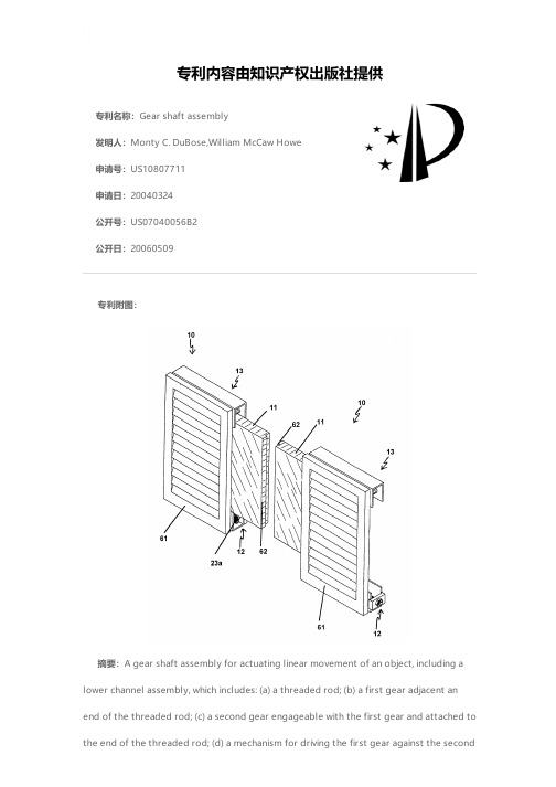
专利名称:Gear shaft assembly发明人:Monty C. DuBose,William McCaw Howe申请号:US10807711申请日:20040324公开号:US07040056B2公开日:20060509专利内容由知识产权出版社提供专利附图:摘要:A gear shaft assembly for actuating linear movement of an object, including a lower channel assembly, which includes: (a) a threaded rod; (b) a first gear adjacent anend of the threaded rod; (c) a second gear engageable with the first gear and attached to the end of the threaded rod; (d) a mechanism for driving the first gear against the secondgear; (e) at least one threaded journal bearing threaded on the correspondingly threaded rod; (f) at least one bearing housing supporting the at least one journal bearing; (g) a movable carrier arm mounted on the threaded rod and attachable to the object; wherein, when the drive mechanism activated, the first gear drives the second gear, rotating the threaded rod, and moving the carrier arm on the threaded rod. A tandem gear shaft assembly and a method for installing a gear shaft assembly and shutter on a window are also included.申请人:Monty C. DuBose,William McCaw Howe地址:299 Coleman Blvd. Mt. Pleasant SC 29464 US,511 Deer St. Mt. Pleasant SC 29464 US国籍:US,US代理机构:Harleston Law Firm,LLC代理人:Kathleen M. Harleston更多信息请下载全文后查看。

专业英语翻译一stressand strain(应力与应变)1the fundamental concepts 基本概念cross section 横截面 the internal stresses produced in the bar 杆的内应力 continuous distribution of hydrostatic pressure 流体静压力 the tensile load 拉伸载荷 a uniform distribution over the cross section 在横截面均匀分布arbitrary cross-sectional shape 任意截面形状tensile stresses 拉应力compressive stresses 压应力a normal stress 正应力through the centroid of the cross sectional area 通过横截面形心the uniform stress condition 压力均匀分布the stress distribution at the ends of the bar 杆末端应力分布 high localized stresses 高度应力集中an axially loaded bar 轴向载荷杆件a tensile strain 拉应变 an elongation or stretching of the material 材料拉伸 a compressive strain 压应变 the ratio of two lengths 两个长度的比值purely statical and geometrical considerations 从纯静态以及几何角度考虑1.That branch of scientific analysis which motions, times and forces is called mechanics and is made up of two parts, statics and dynamics. 研究位移、时间和力运动乘力是科学分析法的一个分支,被称作力学,力学由两大部分组成,静力学和动力学。

Chapter 14 Forging of Metals(金属的锻造/锻压)•14.1 Introduction•14.2 Open-Die Forging•14.3 Impression-Die and Closed-Die Forging•14.4 Related Forging Operations•14.5 Rotary Swaging•14.6 Forging-Die Design•14.7 Die Materials and Lubrication•14.8 Forgeability•14.9 Forging Machines•14.10 Forging Practice and Process Capabilities •14.11 Die Manufacturing Methods; Die Failures •14.12 The Economics of Forging14.1 Introduction•Forging(锻造/锻压)–A workpiece is shaped (formed) by compressive forces applied through various dies(模具)and tools(工具).•one of the oldest metal working processes –4000bc •trationally be performed with a hammer(锤)and anvil(砧/平砧)•mostly require a set of dies and such equipment as a press(压力机)or a forging hammer(锤锻机).•Typical forged products:–bolts (螺栓)–rivets (铆钉)–connecting rods (连杆)–gears (齿轮)–shaft (轴)–hand tool (手工具)–structural components (结构组件)discrete partsForging (锻件)(a)Source : Forging Industry Association.预锻件终锻件近净形/近成品形状净形/最终形状锻造齿净形挤出花键净形bevel gear (伞齿轮)ForgingFigure 14.1 (b) Landing-gear(起落架/着陆装置)components for the C5A and C5B transport aircraft, made by forging. Source: Wyman-Gordon Company.typical forged partsFigure 14.1 (c) general view of a 445 MN (50,000 ton) hydraulic press. Source: Wyman-Gordon Company.Hydraulic Press (液压机)Forging Process (锻压/锻造工艺)Forging Process-2锻造在制坯中的应用•一般机器或机械上的金属零件的传统生产过程是:冶炼——制坯——切削加工——热处理。

机械类外文文献及翻译(文档含中英文对照即英文原文和中文翻译)原文:GEAR AND SHAFT INTRODUCTIONAbstract:The important position of the wheel gear and shaft can't falter in traditional machine and modern machines.The wheel gear and shafts mainly install the direction that delivers the dint at the principal axis box. The passing to process to make them can is divided into many model numbers, using for many situations respectively. So we must be the multilayers to the understanding of the wheel gear and shaft in many ways .Key words: Wheel gear; ShaftIn the force analysis of spur gears, the forces are assumed to act in a single plane. We shall study gears in which the forces have three dimensions. The reason for this, in the case of helical gears, is that the teeth are not parallel to the axis of rotation. And in the case ofbevel gears, the rotational axes are not parallel to each other. There are also other reasons, as we shall learn.Helical gears are used to transmit motion between parallel shafts. The helix angle is the same on each gear, but one gear must have a right-hand helix and the other a left-hand helix. The shape of the tooth is an involute helicoid. If a piece of paper cut in the shape of a parallelogram is wrapped around a cylinder, the angular edge of the paper becomes a helix. If we unwind this paper, each point on the angular edge generates an involute curve. The surface obtained when every point on the edge generates an involute is called an involute helicoid.The initial contact of spur-gear teeth is a line extending all the way across the face of the tooth. The initial contact of helical gear teeth is a point, which changes into a line as the teeth come into more engagement. In spur gears the line of contact is parallel to the axis of the rotation; in helical gears, the line is diagonal across the face of the tooth. It is this gradual of the teeth and the smooth transfer of load from one tooth to another, which give helical gears the ability to transmit heavy loads at high speeds. Helical gears subject the shaft bearings to both radial and thrust loads. When the thrust loads become high or are objectionable for other reasons, it may be desirable to use double helical gears. A double helical gear (herringbone) is equivalent to two helical gears of opposite hand, mounted side by side on the same shaft. They develop opposite thrust reactions and thus cancel out the thrust load. When two or more single helical gears are mounted on the same shaft, the hand of the gears should be selected so as to produce the minimum thrust load.Crossed-helical, or spiral, gears are those in which the shaft centerlines are neither parallel nor intersecting. The teeth of crossed-helical fears have point contact with each other, which changes to line contact as the gears wear in. For this reason they will carry out very small loads and are mainly for instrumental applications, and are definitely not recommended for use in the transmission of power. There is on difference between a crossed heli : cal gear and a helical gear until they are mounted in mesh with each other. They are manufactured in the same way. A pair of meshed crossed helical gears usually have the same hand; that is ,a right-hand driver goes with a right-hand driven. In the design of crossed-helical gears, the minimum sliding velocity is obtained when the helix angle areequal. However, when the helix angle are not equal, the gear with the larger helix angle should be used as the driver if both gears have the same hand.Worm gears are similar to crossed helical gears. The pinion or worm has a small number of teeth, usually one to four, and since they completely wrap around the pitch cylinder they are called threads. Its mating gear is called a worm gear, which is not a true helical gear. A worm and worm gear are used to provide a high angular-velocity reduction between nonintersecting shafts which are usually at right angle. The worm gear is not a helical gear because its face is made concave to fit the curvature of the worm in order to provide line contact instead of point contact. However, a disadvantage of worm gearing is the high sliding velocities across the teeth, the same as with crossed helical gears.Worm gearing are either single or double enveloping. A single-enveloping gearing is onein which the gear wraps around or partially encloses the worm.. A gearing in which each element partially encloses the other is, of course, a double-enveloping worm gearing. The important difference between the two is that area contact exists between the teeth of double-enveloping gears while only line contact between those of single-enveloping gears. The worm and worm gear of a set have the same hand of helix as for crossed helical gears, but the helix angles are usually quite different. The helix angle on the worm is generally quite large, and that on the gear very small. Because of this, it is usual to specify the lead angle on the worm, which is the complement of the worm helix angle, and the helix angle on the gear; the two angles are equal for a 0-deg. Shaft angle.When gears are to be used to transmit motion between intersecting shaft, some of bevel gear is required. Although bevel gear are usually made for a shaft angle of 0 deg. They may be produced for almost any shaft angle. The teeth may be cast, milled, or generated. Only the generated teeth may be classed as accurate. In a typical bevel gear mounting, one of the gear is often mounted outboard of the bearing. This means that shaft deflection can be more pronounced and have a greater effect on the contact of teeth. Another difficulty, which occurs in predicting the stress in bevel-gear teeth, is the fact the teeth are tapered.Straight bevel gears are easy to design and simple to manufacture and give very good results in service if they are mounted accurately and positively. As in the case of squr gears, however, they become noisy at higher values of the pitch-line velocity. In these cases it is often go : od design practice to go to the spiral bevel gear, which is the bevel counterpart of thehelical gear. As in the case of helical gears, spiral bevel gears give a much smoother tooth action than straight bevel gears, and hence are useful where high speed are encountered.It is frequently desirable, as in the case of automotive differential applications, to have gearing similar to bevel gears but with the shaft offset. Such gears are called hypoid gears because their pitch surfaces are hyperboloids of revolution. The tooth action between such gears is a combination of rolling and sliding along a straight line and has much in common with that of worm gears.A shaft is a rotating or stationary member, usually of circular cross section, having mounted upon it such elementsas gears, pulleys, flywheels, cranks, sprockets, and other power-transmission elements. Shaft may be subjected to bending, tension, compression, or torsional loads, acting singly or in combination with one another. When they are combined, one may expect to find both static and fatigue strength to be important design considerations, since a single shaft may be subjected to static stresses, completely reversed, and repeated stresses, all acting at the same time.The word “shaft” covers numerous v ariations, such as axles and spindles. Anaxle is a shaft, wither stationary or rotating, nor subjected to torsion load. A shirt rotating shaft is often called a spindle.When either the lateral or the torsional deflection of a shaft must be held to close limits, the shaft must be sized on the basis of deflection before analyzing the stresses. The reason for this is that, if the shaft is made stiff enough so that the deflection is not too large, it is probable that the resulting stresses will be safe. But by no means should the designer assume that they are safe; it is almost always necessary to calculate them so that he knows they are within acceptable limits. Whenever possible, the power-transmission elements, such as gears or pullets, should be located close to the supporting bearings, This reduces the bending moment, and hence the deflection and bending stress.Although the von Mises-Hencky-Goodman method is difficult to use in design of shaft, it probably comes closest to predicting actual failure. Thus it is a good way of checking a shaft that has already been designed or of discovering why a particular shaft has failed in service. Furthermore, there are a considerable number of shaft-design problems in which the dimension are pretty well limited by other considerations, such as rigidity, and it is only necessary for the designer to discover something about the fillet sizes, heat-treatment,and surface finish and whether or not shot peening is necessary in order to achieve the required life and reliability.Because of the similarity of their functions, clutches and brakes are treated together. In a simplified dynamic representation of a friction clutch, or brake, two in : ertias I and I traveling at the respective angular velocities W and W, one of which may be zero in the case of brake, are to be brought to the same speed by engaging the clutch or brake. Slippage occurs because the two elements are running at different speeds and energy is dissipated during actuation, resulting in a temperature rise. In analyzing the performance of these devices we shall be interested in the actuating force, the torque transmitted, the energy loss and the temperature rise. The torque transmitted is related to the actuating force, the coefficient of friction, and the geometry of the clutch or brake. This is problem in static, which will have to be studied separately for eath geometric configuration. However, temperature rise is related to energy loss and can be studied without regard to the type of brake or clutch because the geometry of interest is the heat-dissipating surfaces. The various types of clutches and brakes may be classified as fllows:. Rim type with internally expanding shoes. Rim type with externally contracting shoes. Band type. Disk or axial type. Cone type. Miscellaneous typeThe analysis of all type of friction clutches and brakes use the same general procedure. The following step are necessary:. Assume or determine the distribution of pressure on the frictional surfaces.. Find a relation between the maximum pressure and the pressure at any point. Apply the condition of statical equilibrium to find (a) the actuating force, (b) the torque, and (c) the support reactions.Miscellaneous clutches include several types, such as the positive-contact clutches, overload-release clutches, overrunning clutches, magnetic fluid clutches, and others.A positive-contact clutch consists of a shift lever and two jaws. The greatest differences between the various types of positive clutches are concerned with the design of the jaws. To provide a longer period of time for shift action during engagement, the jaws may be ratchet-shaped, or gear-tooth-shaped. Sometimes a great many teeth or jaws are used, and they may be cut either circumferentially, so that they engage by cylindrical mating, or on the faces of the mating elements.Although positive clutches are not used to the extent of the frictional-contact type, they do have important applications where synchronous operation is required.Devices such as linear drives or motor-operated screw drivers must run to definite limit and then come to a stop. An overload-release type of clutch is required for these applications. These clutches are usually spring-loaded so as to release at a predetermined toque. The clicking sound which is heard when the overload point is reached is considered to be a desirable signal.An overrunning clutch or coupling permits the driven member of a machine to “freewheel” or “overrun” bec ause the driver is stopped or because another source of power increase the speed of the driven. This : type of clutch usually uses rollers or balls mounted between an outer sleeve and an inner member having flats machined around the periphery. Driving action is obtained by wedging the rollers between the sleeve and the flats. The clutch is therefore equivalent to a pawl and ratchet with an infinite number of teeth.Magnetic fluid clutch or brake is a relatively new development which has two parallel magnetic plates. Between these plates is a lubricated magnetic powder mixture. An electromagnetic coil is inserted somewhere in the magnetic circuit. By varying the excitation to this coil, the shearing strength of the magnetic fluid mixture may be accurately controlled. Thus any condition from a full slip to a frozen lockup may be obtained.齿轮和轴的介绍摘要:在传统机械和现代机械中齿轮和轴的重要地位是不可动摇的。
GEAR AND SHAFT INTRODUCTIONAbstract: The important position of the wheel gear and shaft can't falter in traditional machine and modern machines.The wheel gear and shafts mainly install the direction that delivers the dint at the principal axis box.The passing to process to make them can is divided into many model numbers, useding for many situations respectively.So we must be the multilayers to the understanding of the wheel gear and shaft in many ways .Key words: Wheel gear;ShaftIn the force analysis of spur gears, the forces are assumed to act in a single plane. We shall study gears in which the forces have three dimensions. The reason for this, in the case of helical gears, is that the teeth are not parallel to the axis of rotation. And in the case of bevel gears, the rotational axes are not parallel to each other. There are also other reasons, as we shall learn.Helical gears are used to transmit motion between parallel shafts. The helix angle is the same on each gear, but one gear must have a right-hand helix and the other a left-hand helix. The shape of the tooth is an involute helicoid. If a piece of paper cut in the shape of a parallelogram is wrapped around a cylinder, the angular edge of the paper becomes a helix. If we unwind this paper, each point on the angular edge generates an involute curve. The surface obtained when every point on the edge generates an involute is called an involute helicoid.The initial contact of spur-gear teeth is a line extending all the way across the face of the tooth. The initial contact of helical gear teeth is a point, which changes into a line as the teeth come into more engagement. In spur gears the line of contact is parallel to the axis of the rotation; in helical gears, the line is diagonal across the face of the tooth. It is this gradual of the teeth and the smooth transfer of load from one tooth to another, which give helical gears the ability to transmit heavy loads at high speeds. Helical gears subject the shaft bearings to both radial and thrust loads. When the thrust loads become high or are objectionable for other reasons, it may be desirable to use double helical gears. A double helical gear (herringbone) is equivalent to two helical gears of opposite hand, mounted side by side on the same shaft. They develop opposite thrust reactions and thus cancel out the thrust load. When two or more single helical gears are mounted on the same shaft, the hand of the gears should be selected so as to produce the minimum thrust load.Crossed-helical, or spiral, gears are those in which the shaft centerlines are neitherparallel nor intersecting. The teeth of crossed-helical fears have point contact with each other, which changes to line contact as the gears wear in. For this reason they will carry out very small loads and are mainly for instrumental applications, and are definitely not recommended for use in the transmission of power. There is on difference between a crossed helical gear and a helical gear until they are mounted in mesh with each other. They are manufactured in the same way. A pair of meshed crossed helical gears usually have the same hand; that is ,a right-hand driver goes with a right-hand driven. In the design of crossed-helical gears, the minimum sliding velocity is obtained when the helix angle are equal. However, when the helix angle are not equal, the gear with the larger helix angle should be used as the driver if both gears have the same hand.Worm gears are similar to crossed helical gears. The pinion or worm has a small number of teeth, usually one to four, and since they completely wrap around the pitch cylinder they are called threads. Its mating gear is called a worm gear, which is not a true helical gear. A worm and worm gear are used to provide a high angular-velocity reduction between nonintersecting shafts which are usually at right angle. The worm gear is not a helical gear because its face is made concave to fit the curvature of the worm in order to provide line contact instead of point contact. However, a disadvantage of worm gearing is the high sliding velocities across the teeth, the same as with crossed helical gears.Worm gearing are either single or double enveloping. A single-enveloping gearing is one in which the gear wraps around or partially encloses the worm.. A gearing in which each element partially encloses the other is, of course, a double-enveloping worm gearing. The important difference between the two is that area contact exists between the teeth of double-enveloping gears while only line contact between those of single-enveloping gears. The worm and worm gear of a set have the same hand of helix as for crossed helical gears, but the helix angles are usually quite different. The helix angle on the worm is generally quite large, and that on the gear very small. Because of this, it is usual to specify the lead angle on the worm, which is the complement of the worm helix angle, and the helix angle on the gear; the two angles are equal for a 90-deg. Shaft angle.When gears are to be used to transmit motion between intersecting shaft, some of bevel gear is required. Although bevel gear are usually made for a shaft angle of 90 deg. They may be produced for almost any shaft angle. The teeth may be cast, milled, or generated. Only the generated teeth may be classed as accurate. In a typical bevel gear mounting, one of the gear is often mounted outboard of the bearing. This means that shaft deflection can be morepronounced and have a greater effect on the contact of teeth. Another difficulty, which occurs in predicting the stress in bevel-gear teeth, is the fact the teeth are tapered.Straight bevel gears are easy to design and simple to manufacture and give very good results in service if they are mounted accurately and positively. As in the case of squr gears, however, they become noisy at higher values of the pitch-line velocity. In these cases it is often good design practice to go to the spiral bevel gear, which is the bevel counterpart of the helical gear. As in the case of helical gears, spiral bevel gears give a much smoother tooth action than straight bevel gears, and hence are useful where high speed are encountered.It is frequently desirable, as in the case of automotive differential applications, to have gearing similar to bevel gears but with the shaft offset. Such gears are called hypoid gears because their pitch surfaces are hyperboloids of revolution. The tooth action between such gears is a combination of rolling and sliding along a straight line and has much in common with that of worm gears.A shaft is a rotating or stationary member, usually of circular cross section, having mounted upon it such elementsas gears, pulleys, flywheels, cranks, sprockets, and other power-transmission elements. Shaft may be subjected to bending, tension, compression, or torsional loads, acting singly or in combination with one another. When they are combined, one may expect to find both static and fatigue strength to be important design considerations, since a single shaft may be subjected to static stresses, completely reversed, and repeated stresses, all acting at the same time.The word “shaft” covers numerous variations, such as axles and spindles. Anaxle is a shaft, wither stationary or rotating, nor subjected to torsion load. A shirt rotating shaft is often called a spindle.When either the lateral or the torsional deflection of a shaft must be held to close limits, the shaft must be sized on the basis of deflection before analyzing the stresses. The reason for this is that, if the shaft is made stiff enough so that the deflection is not too large, it is probable that the resulting stresses will be safe. But by no means should the designer assume that they are safe; it is almost always necessary to calculate them so that he knows they are within acceptable limits. Whenever possible, the power-transmission elements, such as gears or pullets, should be located close to the supporting bearings, This reduces the bending moment, and hence the deflection and bending stress.。
英文原文:SHAFT AND GEAR DESIGNAbstract: The important position of the wheel gear and shaft can' t falter in traditional machine and modern machines. The wheel gear and shafts mainly install the direction that delivers the dint at the principal axis box. The passing to process to make them can is divided into many model numbers, useding for many situations respectively. So we must be the multilayers to the understanding of the wheel gear and shaft in many waysKey words : Wheel gear ; ShaftIn the force analysis of spur gears, the forces are assumed to act in a single plane .We shall study gears in which the forces have three dimensions.The reason for this, in the case of helical gears, is that the teeth are not parallel to the axis of rotation. And in the case of bevel gears, the rotational axes are not parallel to each other. There are also other reasons, as we shall learn.Helical gears are used to transmit motion between parallel shafts. The helix angle is the same on each gear, but one gear must have a right-hand helix and the other a left-hand helix. The shape of the tooth is an involute helicoid. If a piece of paper cut in the shape of a parallelogram is wrapped around a cylinder, the angular edge of the paper becomes a helix. If we unwind this paper, each point on the angular edge generates an involute curve. The surface obtained when every point on the edge generates an involute is called an involute helicoid. The initial contact of spur-gear teeth is a line extending all the way across the face of the tooth. The initial contact of helical gear teeth is a point, which changes into a line as the teeth come into more engagement. In spur gears the line of contact is parallel to the axis of the rotation; in helical gears, the line is diagonal across the face of the tooth. It is this gradual of the teeth and the smooth transfer of load from one tooth to another, which give helical gears the ability to transmit heavy loads at high speeds. Helical gears subject the shaft bearings to both radial and thrust loads. When the thrust loads become high or are objectionable for other reasons, it may be desirable to use double helical gears. A double helical gear (herringbone) is equivalent to two helical gears of opposite hand, mounted side byside on the same shaft. They develop opposite thrust reactions and thus cancel out the thrust load. When two or more single helical gears are mounted on the same shaft,the hand of the gears should be selected so as to produce the minimum thrust load Crossed-helical, or spiral, gears are those in which the shaft centerlines are neither parallel nor intersecting. The teeth of crossed-helical fears have point contact with each other, which changes to line contact as the gears wear in. For this reason they will carry out very small loads and are mainly for instrumental applications, and are definitely not recommended for use in the transmission of power There is on difference between a crossed heli cal gear and a helical gear until they are mounted in mesh with each other. They are manufactured in the same way. A pair of meshed crossed helical gears usually have the same hand; that is , a right-hand driver goes with a right-hand driven. In the design of crossed-helical gears, the minimum sliding velocity is obtained when the helix angle are equal. However, when the helix angle are not equal, the gear with the larger helix angle should be used as the driver if both gears have the same handWorm gears are similar to crossed helical gears. The pinion or worm has a small number of teeth, usually one to four, and since they completely wrap around the pitch cylinder they are called threads. Its mating gear is called a worm gear, which is not a true helical gear. A worm and wormgear are used to provide a high angular-velocity reduction between nonintersecting shafts which are usually at right angle. The worm gear is not a helical gear because its face is made concave to fit the curvature of the worm in order to provide line contact instead of point contact. However, a disadvantage of worm gearing is the high sliding velocities across the teeth, the same as with crossed helical gearsWorm gearing are either single or double enveloping. A single-enveloping gearing is one in which the gear wraps around or partially encloses the worm. . A gearing in which each element partially encloses the other is, of course, a double-enveloping worm gearing. The important difference between the two is that area contact exists between the teeth of doubleenveloping gears while only line contact between those of single-enveloping gears. The worm and worm gear of a set have the same hand ofhelix as for crossed helical gears, but the helix angles are usually quite different The helix angle on the worm is generally quite large, and that on the gear very small Because of this, it is usual to specify the lead angle on the worm, which is the complement of the worm helix angle, and the helix angle on the gear; the two angles are equal for a 90-deg. Shaft angleWhen gears are to be used to transmit motion between intersecting shaft, some of bevel gear is required. Although bevel gear are usually made for a shaft angle of 90 deg. They may be produced for almost any shaft angle. The teeth may be cast, milled, or generated. Only the generated teeth may be classed as accurate. In a typical bevel gear mounting, one of the gear is often mounted outboard of the bearing. This means that shaft deflection can be more pronounced and have a greater effect on the contact of teeth. Another difficulty, which occurs in predicting the stress in bevel-gear teeth, is the fact the teeth are tapered.Straight bevel gears are easy to design and simple to manufacture and give very good results in service if they are mounted accurately and positively. As in the case of squr gears, however, they become noisy at higher values of the pitch-line velocity In these cases it is often go od design practice to go to the spiral bevel gear, which is the bevel counterpart of the helical gear. As in the case of helical gears, spiral bevel gears give a much smoother tooth action than straight bevel gears, and hence are useful where high speed are encountered. It is frequently desirable, as in the case of automotive differential applications, to have gearing similar to bevel gears but with the shaft offset. Such gears are called hypoid gears because their pitch surfaces are hyperboloids of revolution The tooth action between such gears is a combination of rolling and sliding alonga straight line and has much in common with that of worm gears A shaft is a rotating or stationary member, usually of circular cross section, having mounted upon it such elementsas gears, pulleys, flywheels, cranks, sprockets, and other power-transmission elements. Shaft may be subjected to bending, tension, compression, or torsional loads, acting singly or in combination with one another. When they are combined, one may expect to find both static and fatigue strength tobe important design considerations, since a single shaft may be subjected to static stresses, completely reversed, and repeated stresses, all acting at the same time The word "shaft" covers numerous variations, such as axles and spindles. Anaxle is a shaft, wither stationary or rotating, nor subjected to torsion load. A shirt rotating shaft is often called a spindle. When either the lateral or the torsional deflection of a shaft must be held to close limits, the shaft must be sized on the basis of deflection before analyzing the stresses. The reason for this is that, if the shaft is made stiff enough so that the deflection is not too large, it is probable that the resulting stresses will be safe. But by no means should the designer assume that they are safe; it is almost always necessary to calculatethem so that he knows they are within acceptable limits Whenever possible, the power-transruission elements, such as gears or pullets, should be located close to the supporting bearings, This reduces the bending moment, and hence the deflection and bending stress.Although the von Mises-Hencky-Goodman method is difficult to use in design of shaft, it probably comes closest to predicting actual failure. Thus it is a good way of checking a shaft that has already been designed or of discovering why a particular shaft has failed in service. Furthermore, there are a considerable number of shaft-design problems in which the dimension are pretty well limited by other considerations, such as rigidity, and it is only necessary for the designer to discover something about the fillet sizes, heat-treatment, and surface finish and whether or not shot peening is necessary in order to achieve the required life and reliability Because of the similarity of their functions, clutches and brakes are treated together. In a simplified dynamic representation of a friction clutch, or brake two in ertias 11 and 12 traveling at the respective angular velocities Wl and W2, one of which may be zero in the case of brake, are to be brought to the same speed by engaging the clutch or brake. Slippage occurs because the two elements are running at different speeds and energy is dissipated during actuation, resulting in a temperature rise. In analyzing the performance of these devices we shall beinterested in the actuating force, the torque transmitted, the energy loss and the temperature rise. The torque transmitted is related to the actuating force, the coefficient of friction, and the geometry of the clutch or brake. This is problem in static, which will have to be studied separately for eath geometric configuration. However, temperature rise is related to energy loss and can be studied without regard to the type of brake or clutch because the geometry of interest is the heat-dissipating surfaces. The various types of clutches and brakes may be classified as fllows1. Rim type with internally expanding shoes2. Rim type with externally contracting shoes3。
CHAPTER 19Gears, Shafts, and BearingsLearning ObjectivesUpon completion of this chapter you will be able to accomplish the following:1. Recognize mechanical devices that are designed to transmit motion from onemachine element to another.2. Analyze gear blank stock material, types of hubs, and methods of attaching gears toshafts.3. Define the various gear categories and basic specifications for manufacture andinspection.4. Explain common gear terms and symbols.5. Demonstrate an understanding of gear, shaft, and bearing drawing practices.6. Develop ability to communicate gear, shaft, and bearing data by means of ANSIstandard dimensioning and notation.7. Define the types and purposes of bearings and their respective housings andmountings.8. Explore the use of CAD in gear design.19.1 IntroductionThis chapter covers mechanical devices designed to transmit motion from one machine element to another. Most gears (Fig. 19.1) are mounted on shafts, which, in turn, are secured by bearings installed in a variety of housings. Gears are designed to transfer rotary motion from one shaft to another. The speed of the motion is increased or decreased by changing the size of the drive gear and the driven gear.The selection of gear types is based on the relative position of the shafts. The shafts will be either intersecting, non intersecting, or parallel. Shafts can be positioned perpendicular, parallel, or at any given angle to each other, depending on the design application. Figure 19.2 shows two spur gears mounted on parallel shafts. Shaft A holds the drive gear; shaft B holds the driven gear. Spur gears are commonly used to transfer motion from one parallel shaft to another. In this example, the drive gear is smaller than the driven gear; therefore, the driven gear will take longer to complete one revolution and its speed will be less than that of the drive gear.Some gears are designed to change rotary motion into reciprocating (linear--back and forth) motion. These machine elements are called pinions and gear racks. Another method of transmitting rotary motion into reciprocating (linear--up and down) motion utilizes a cam and follower assembly. This method is discussed in Chapter 20, CAMS.Whether the transfer of motion is rotary to rotary or rotary to linear, the rotary element must be mounted on some kind of a shaft and that shaft must rotate freely Therefore, shafts ride on bearings [Fig. 19.3(a)]. The gear itself may have a integral keyseat to provide a positive connection to the shaft (Figure 19.3(b)].19.2 GearsThis chapter introduces the most common types of gears, shows how they are represented on drawings, and provides methods for calling out their specifications. Gear specifications are the most important information that is supplied to the gear manufacturer. Gears come in many styles, including spur gears, pinions, ring gears, worm gears, bevel gears, miter gear, hypoid bevel gears, racks, and others. Gears are made of metals and nonmetals. Spur gears are the most common gear type manufactured.19.2.1 Gear TeethGear teeth are projections designed to fit into the tooth spaces of mating gears and contact mating teeth along a common line known as the pressure line. The pressure line is also called the line of action (Fig. 19.4). The most common form for the tooth flank is involute. The pressure line determines the particular involute shape. The American National Standards Institute (ANSl) has standardized two pressure angles 14 1/2° (now rarely used) and 20° (Fig. 19.5).19.2.2 Gears, Splines and Serrations, and RacksThe following terms and descriptions define the general gear categories covered in the chapter:Spur gears Gears connecting parallel shafts and having straight teeth elements (parallel to the axis of the shafts). The smaller gear of a pair of gears is called a pinion.Helical gears Gears connecting shafts with projected non intersecting centerlines. Helical gear teeth elements are spiral or helical in shape.Bevel and miter gears Gears that are conical in form and operate on shafts having projected intersecting centerlines. When the gears are different sizes, they are called bevel gears. Bevel gears of the same size (one-to-one ratio) with shafts intersecting at right angles, are called miter gears.Internal gears Gears connecting parallel shafts, with teeth elements that are either straight or helical and with a pitch circle that is tangent internally to the mating spur or spiral gear.Worm gears Gears connecting non parallel, non intersecting shafts. They have teeth elements that are helical. Womm gearing generally is composed of a worm (screw) and womm wheel (gear) in matched sets.Rack gear A rack may be considered to be a gear of an infinitely long pitch radius. The pitch line of a rack is a straight line; the pitch is described as the linear pitch. A rack gear is a flat spur gear.Splines and serrations Splines and serrations are multiple keys used to prevent relative rotation between two members, in the general form of internal and external gear teeth. Splines are used primarily to transmit torque.19.2.3 Gear BlanksThe gear blank is the stock material from which the gear is cut. The blank must have sufficient rigidity to prevent distortion during tooth cutting. The type of hub (split, solid, or hubless) and the type of gear (spoked, flanged, or flat) must also be determined. Hub variations are shown in Figure 19.6. Still another factor to consider in the selection of the gear blank is the method of attaching the gear to its shaft. Some of the more common methods employed are:Keys Permits easy assembly and disassembly. The design must insure that the key is captive when the assembly is complete.Pins Requires drilling at assembly. This tends to weaken small shafts and does not permit replacement of gear or shaft. This method provides a positive engagement between gear and shaft.Set screws Permits easy assembly and disassembly. This method should always use two set screws at 45 -90° to each other. Set screws at a 60° angle are the strongest. The design of the shaft should provide flats on the shaft as a bearing surface for the set screw. Some method of retaining the set screw must be provided. This method is not appropriate when large torque loads are transmitted.Adhesive bond Requires considerable care at assembly to ensure a good bond. Adhesive has temperature and torque limitations. Disassembly is very difficult without destroying parts of the assembly. The adhesive chosen must be compatible with gear and shaft materials.Mechanical stake This method has moderate torque transmitting capacity and may not permit replacement of gear or shaft.Clamp Can only be used with split hub gears, are bulky in size, and have only moderate torque capacity This method is easy to assemble and disassemble.Press This method is not acceptable when shaft cannot be isolated from the bearings as in a motor. Disassembly is difficult. Materials must not expand or contract and cause a loose fit at temperature extremes.19.3 Spur GearsTwo friction wheels with surfaces in contact are shown in Figure 19.7. If one of the wheels is turned--and no slipping occurs--the other one will turn. To prevent slipping, gear teeth may be added to both wheels, with corresponding recesses in each wheel. In Figure 19.8 the the spaces are cut on a spur gear by a machine tool. Spur gears are mounted on parallel axes and are manufactured in both internal and external versions. Terms are given in Figure 19.9(a) and (b) for gears with the involute form of gear teeth. A gear and pinion are shown in this figure. A pinion is the smaller of two gears in a mating set. The pitch circles in Figure 19.9(a) are tangent and might be thought of as representing the friction wheels. The pitch circles on spur gears are tangent circles. Spur gears are manufactured in both internal and external versions.19.3.1 Internal Spur Gear (Ring Gear)An internal gear has greater tooth strength for a given tooth size. Internal spur gears permit a closer center distance that may enable a more compact design and allow input(drive) and output (driven) shafts to rotate in the same direction. Figure 19.10 illustrates the center-to-center distance between a ring gear and a pinion gear. Ring gears can have spur or helical tooth forms. In Figure 19.11 (a and b) an internal spur gear and a pinion are shown. This matching set was designed on a CAD system and physically modeled using Sterolithography.19.3.2 External Spur GearThe external spur gear (Fig.19.12)is the most common and best known type of gear. It transmits motion between parallel shafts that rotate in opposite directions. Spur gears generate radial bearing loads. Because of their availability and ease of manufac-ture, they should be given first consideration as the choice of gear type19.3.3 Spur Gear SpecificationsThe basic specifications for both manufacturing and inspection for a spur gear is shown below:· pressure angle · number of pinion teeth· tooth form · material· AGMA quality number · number of gear teeth· diametral pitch · face width· tooth thickness, circular · pitch diameter· measuring-wire size · measurement over wires· total composite error · gear testing radius· testing pressure · surface finish· outside diameterTo provide the required data listed above the application requirements must be known. This information should include speed, ratio, power, accuracy, life, temperature, and application.19.3.4 Spur Gear Terms and SymbolsMany terms will be understood by an examination of Figure 19.9 (a) and (b). The addendum is the height of the tooth, from the pitch circle to the outside circle. The base circle is the circle used for generating the involute curve. The line of action is the line along which the contact between the teeth takes place. Some of the symbols used for gears include:a = addendumb = dedendumc = clearance D = pitch diameterOD = outside diameter N = number of teethP = diametral pitch p = circular pitchThe following terms are used throughout the chapter to describe spur and helical gears:Addendum The height that a tooth projects beyond the pitch circle or pitch line.Base diameter The diameter of the base cylinder from which the involute portion of a tooth profile is generated.Backlash The amount by which the width of a tooth space exceeds the thickness of the engaging tooth on the pitch circles.Center distance The distance between the parallel axis of spur gears and parallel helical gears, or the crossed axes of crossed helical gears.Circular pitch The distance along the pitch circle or pitch line between corresponding profiles of adjacent teeth.Dedendum The depth of a tooth space below the pitch line. It is normally greater than the addendum of the mating gear to provide clearance.Diametral pitch The ratio of the number of teeth to the pitch diameter in inches.Face width The length of the teeth in an axial plane.Hub diameter The outside diameter of a gear, sprocket, or coupling hub.Hub projection The distance the hub extends beyond the gear face.Involute teeth The teeth of spur gears, helical gears, and worms where the active portion of the profile in the transverse plane is the involute of a circle.Lead The axial advance of a helix for one complete turn, as in the threads of cylindrical worms and teeth of helical gears.Normal diametral pitch The value of the diametral pitch as calculated in the normal plane of a helical gear or worm.Normal plane The plane normal to the tooth surface at a pitch point and perpendicular to the pitch plane. Outside diameter The diameter of the addendum (outside) circle of a gear.Pinion A machine part with gear teeth. When two gears run together, the one with the smaller number of teeth is called the pinion.Pitch circle The circle derived from a number of teeth and a specified diametral or circular pitch. The circle on which spacing or tooth profiles is established and from which the tooth proportions are constructed.Pitch diameter The diameter of the pitch circle. In parallel shaft gears, the pitch diameters can be determined directly from the center distance and the number of teeth.Pressure angle The angle between a tooth profile and a radial line at its pitch point. In involute teeth, pressure angle is often described as the angle between the line of action and the line tangent to the pitch circle.Root diameter The diameter at the base of the tooth spaceTransverse diametral The ratio of the number of teeth to the pitch diameter, in inches, for a helical gear. Whole depth The total depth of a tooth space, equal to addendum plus dedendum, equal to the working depth plus varianceWorking depth The depth of engagement of two gears.19.3.5 Diametral Pitch SystemAll stock gears are made in accordance with the diametral pitch system. The diametral pitch of a gear is the number of gear teeth for each inch of pitch diameter. Therefore, the diametral pitch specifies the size of the gear tooth; a smaller diametral pitch indicates a larger tooth. An eight pitch gear has eight teeth for each inch of pitch diameter (for a 6 in. pitch diameter, 6 x 8 = 48 teeth). The circular pitch is thedistance from a point on one tooth to the corresponding point on the next tooth. This distance is measured along the pitch circle.Gear teeth can be manufactured with a wide variety of shapes and profiles. The involute profile is the most commonly used system for gearing today, and most standard spur and helical gears are of involute form. An involute is a curve that is traced by a point on a taut cord unwinding from a circle, called a base circle. The involute is a form of spiral, the curvature of which becomes straighter as it is drawn from a base circle. Eventually, if drawn far enough, it would become a straight line.19.3.6 Pressure AnglePressure angle (PA) (Fig. 19.5) is defined as the angle formed between the normal to the tooth profile at the pitch circle, and the tangent to the pitch circle at that point.Standard gears are manufactured in both 14 1/2° and 20° PA, involute, full-depth system gears. 20° PA has a higher load carrying capacity, but 14 1/2°PA gears are still in existence. The spur gear detail shown in Figure 19.12 has a pressure angle of 14 1/2°, a pitch diameter of 12.00 in., and a diametral pitch of 4. Therefore, the gear has 12 x 4 = 48 teeth. For gears to mesh, they must have the same diametral pitch.19.3.7 Spur Gear FormulasTable 19.1 shows a complete set of spur gear formulae for full-depth involute teeth. Standard tooth proportions for the 20° fine-pitch system are as follows:a = addendum = 1.000/Pb = dedendum = 1.200/P + 0.002c = clearance = 0.200/P + 0.002h k = working depth of tooth = 2.000/Ph l = total depth of tooth = 2.200/P + 0.002D = pitch diameter = N/POD = outside diameter = D + 2/PN = number of teethP = diametral pitch = N/DTooth proportions for the standard 14 1/2° full-depth involute system are as follows:a = addendum = I/Pb = dedendum = 1 157/Pc = clearance = 0.157/Ph k = working depth = 2/Ph l = total depth = 2.157/PD = pitch diameter = N/POD = outside diameter = D + 2/PN = number of teethP = diametral pitch = N/D19.3.8 Spur and Helical Gear Teeth RepresentationViews of external spur and helical gears are drawn as shown in Figure 19.13. Gear tooth outlines can normally be omitted from the drawing. Outlines are shown where needed for orientation with other features of the gear or where details, such as tip chamfers or reliefs, require dimensioning. Where required, one tooth may be shown [Fig. 19.13(a)]. Notice that all the teeth are shown in Figure 19.12. This is because a CAD system was used to draw the gear detail. The designer constructed only one tooth and then rotated and copied (ARRAY on AutoCAD) the tooth the required number of times (48 in the example). When gears are drawn manually, a template is almost always used to construct the gear teeth.19.3.9 Gear Tooth ThicknessCircular or arc tooth thickness is the preferred specification; chordal tooth thickness may be used. Tooth thickness is normally specified at the referenced pitch circle. Figure 19.14 shows gear teeth terms in detail. If measurements such as with pins or balls (Fig. 19.14) are specified in addition to the actual tooth thickness, thesemeasurements must be labeled "reference," or labeled as in Figure 19.15, where the dimension is given "OVER PIN." The diameter of pins or balls (Fig. 19.15) must be expressed beyond four decimal places as appropriate. The diameter of pins or balls is basic.Tooth thickness must be designated "actual" or "functional." Functional tooth thickness is a specification at the referenced pitch circle for definitive backlash control. It may be used in place of, or in addition to actual tooth thickness. However, if the actual tooth thickness is critical, it should be specified in addition to the functional tooth thickness. Table 19.2 shows standard tooth dimensions for spur gears.19.3.10 Backlash on Spur GearsBacklash is the motion of a meshed gear when its mate is held fixed. An increase or decrease in center distance will cause an increase or decrease in backlash. Stock spur gears are cut to operate at standard center distances (Figs. 19.9 and 19.10). The standard center distance is defined by:Pinion PD + Gear PDstandard center distance = 219.4 Helical GearsThe information contained in the spur gear section is also applicable to helical gears with the addition of helix angle and lead. Helix angle is the angle between any helix and an element of its cylinder. In helical gears (Fig. 19.16), it is at the pitch diameter, unless otherwise specified. Lead for helical gears is the axial advance of a helix for one complete turn, for instance, as in the threads of cylindrical worms and teeth of helical gears. Figure 19.17 provides helical gear terminology.Many standard helical gears are cut to the diametral pitch system. This results in a normal pitch that is smaller than the diametral pitch. Normal diametral pitch is the diametral pitch calculated in the normal plane.Helical gears of the same hand operate at right angles. Helical gears of opposite hands run on parallel shafts.The helical tooth form is involute in the plane of rotation and can be developed in a manner similar to that of the spur gear. However, unlike the spur gear, which may be viewed as two dimensional, the helical gear must be viewed as three dimensional to show changes in axial features. Formulas for helical gears are provided in Table 19.3.19.5 Racks and PinionsA rack may be considered to be a gear of infinitely long pitch radius. The pitch line of a rack is a straight line; the pitch is described as the linear pitch. Racks can have spur or helical teeth. Figure 19.18 shows a standard rack detail. Racks are designed tomate with a pinion (gear) and are used to convert rotary motion into linear motion or the reverse.19.6 SplinesSplines are multiple keys, in the general form of internal and external gear teeth, used to prevent relative rotation between two members. Splines are used primarily to transmit torque and are usually integral with shafts that include other features as in Figure 19.19 where the end of the shaft is a spline and the center is a worm screw. Splines (Fig. 19.20) are normally used in three applications:1. for coupling shafts when heavy torque’s are transmitted without slippage2. for attaching parts that require removal for indexing or for change of angular position3. for transmitting power to permanently fixed gears, pulleys, and other rotating devicesInvolute splines (Fig. 19.20) are similar in form to external or internal involute gears. The general graphic format for depicting spline teeth is the same as for spur gears. Standard involute splines are manufactured with 30︒, 37 1/2︒, and 45° pressure angles.19.7 Gear Drawing PracticesAn axial view and a plane of rotation view are generally sufficient to illustrate a gear. Additional views may be used to show construction and special features or relations. The axial view is usually made in section, on a plane parallel to the axis (Fig. 19.12). A gear, pinion, or worm integral with a shaft, or a helical gear is shown in full view, on a plane parallel to the axis (Fig. 19.19). The pitch diameter is shown by conventional centerlines and the root diameter by hidden lines. In an axial section view, visible lines are used to represent the outside and root diameter, and centerlines for the pitch diameter.In views representing planes of rotation, the outside and root diameters are shown by phantom lines and, when several teeth are shown, the pitch diameter is shown by a centerline [Fig. 19.13(a)]. When no teeth are shown, the outside diameter is represented by a visible object line, and the root diameter by a hidden line [Fig.19.13(b)]. The pitch diameter is still represented by a centerline. Figure 19.21 is an actual industry detail drawing of a gear.In most cases, it is not necessary to draw all gear teeth when detailing gears. If it is necessary to illustrate a relation to some other feature, such as a keyseat or bolt hole, or to show dimensions across pins, one or more teeth may be shown. An enlarged view or section should be used to show special features of gear teeth or a gear profile. Gear teeth may be drawn by the approximate method shown in Figures 19.22 or 19.23. The relative size of gear teeth in terms of diametral pitch is illustrated full size in Figure 19.24.19.7.1 Dimensioning and NotesGear data must be grouped as shown in Figures 19.12 and 19.15. The location of the gear data on the drawing is arbitrary. However, if more than one gear is depicted on a drawing, the groups of gear data must be clearly referenced to the appropriate gear.The major diameter may be specified as the outside diameter and the minor diameter may be specified as the root diameter. This is for external gears only. On internal gears, the major diameter may be specified as the root diameter and the minor diameter may be specified as the inside diameter.Illustrations show only those dimensions that control the gear teeth and their relation to the specified mounting. All other dimensions and specifications must conform to recommended drafting practice (ANSI). Dimensional values are indicated by X's on the rack in Figure 19.25 to show the number of decimal places recommended in each instance.A completely defined rack or gear contains two sets of dimensions: those of the gear blank and those of the gear teeth. This information is shown as a composite on one set of views. Information required for the production of a gear blank is shown on the face of the gear drawing, integral with the graphic depiction. Information required for the production of the gear teeth is shown on the same drawing in a data block. Local and general notes are added as required. Angular dimensions are expressed in degrees and decimal portions thereof (where desired, the angle may be given in degrees, minutes, and seconds). Figure 19.26 shows a matching set of spur gears along with all dimensions required for manuacture.19.8 Bevel GearsPortions of two cones in frictional contact (Fig. 19.27) might be used to transmit motion from one shaft to another. However, to prevent slipping, teeth may be used. The cones then become bevel gears (Fig. 19.28). Two bevel gears of the same size, with shafts at right angles, are called miter gears (Figure 19.29). Bevel gears are the most common method of transmitting motion between shafts with intersecting axes. The addendum and dedendum are measured the same as the spur gear and are measured on a cone, called the back cone. The diametral pitch, circular pitch, etc., are the same as for a spur gear.The shafts for bevel gears may make any angle, called the shaft angle, with each other. The terms used for bevel gears are given in Figure 19.29.19.8.1 Bevel Gear Terminology and FormulasBevel gears (Fig. 19.30) are frequently matched in sets or pairs during sequence of the manufacturing process. They are maintained as a matched set in assembly. Formulas for straight bevel gears are given in Table 19.4. Since they differ from spur gears, the gear tooth nomenclature that follows is presented to familiarize you with general terms used on the bevel gear drawings:Addendum The distance from the pitch cone to the top of the tooth, as measured at the large end of the tooth.Axial plane A plane that contains the gear axis.Back angle distance The perpendicular distance from the intersection of the gear axis with the locating surface at the back of a bevel gear to the back cone element.Circular thickness The length of arc between the two sides of a gear tooth on the pitch circle.Face angle distance The perpendicular distance from the intersection of the gear axis with the locating surface at the back of a bevel gear to the face cone element.Mounting distance (MD) The distance from the end of the hub of one gear to the center line of its mating gear (Fig. 19.30).Pitch plane A plane tangent to the gear pitch surface. The pitch plane is tangent to the pitch cone for bevel gears.Pressure angle The angle at the pitch point between a line normal to the tooth profile and the pitch plane.Spiral angle The angle between the tooth trace and an element of the pitch cone.Tooth form The shape of the tooth profile. Since bevel gears are manufactured with a variety of tooth forms, it is essential to specify the desired form on the gear drawing.19.8.2 Drawing and Dimensioning Bevel GearsA bevel gear drawing consists of a side view or axial section illustrating the general configuration and tabulated gear tooth data. Generally, only one view is needed. A front view is used where necessary to show the relationship of the gear teeth to other features.The spiral bevel gear illustration in Figure 19.31 shows only those dimensions that control the gear teeth and their relation to the mounting surfaces. Dimensional values are indicated by X's to show the number of decimal places recommended in each instance.19.9 Worms and Worm GearsWorm gears (Fig. 19.32) are used to transmit motion from one shaft to another at a high speed. Worm gears (wheel) and worm screws are designed to transmit motion between non intersecting, perpendicular shafts. A worm is, in effect, a screw. When a worm wheel (similar to a spur gear) has teeth shaped to fit the threads on the worm, the worm will turn the wheel. The worm may have single, double, or multiple threads. A large speed ratio is possible with this type of gearing; however, a worm drive only works as a reducer. When the worm gear drives the worm screw (speed increases), the drive locks up.Specifications and dimensions required for a worm gear set are provided in Figure 19.33. A detail of a worm wheel and worm gear are shown in Figure 19.34. Sometimes a worm gear is combined with a pinion.Standard stock worms and worm gears are used for the transmission of motion and/or power between non intersecting shafts at right angles (90°). Worm gear drives are considered the smoothest and quietest form of gearing. In most cases, a worm andworm wheel are detailed on separate sheets. Worm and worm gear formulae are provided in Table 19.5.19.10 CAD and GearsCAD systems can be used to design and detail gears. Since the system has the capability to rotate and copy graphics (even in 3D), only one tooth is drawn and then time-saving commands are used. Figure 19.34 was drawn on a CAD system. The de-signer in Figure 19.35 is working at his terminal creating a 3D surface model of a spur gear tooth.If a CAD system had not been used, only one tooth would have been drawn for each gear. For AutoCAD the ARRAY command with the Polar option is used to rotate and copy the gear teeth as shown below:Command: ARRAY Select Objects: Window the tooth that was drawn. Rectangular or Polar Array (R/P): PCenter point of array: Pick the center of the gear.Number of items: 32Angle to fill (+=CCW, -=CW) <360>: <Return> to choose 360 default.Rotate objects as they are copied? <y>: <Return> for default.You May Complete Exercises 19.1 Through 19.4 at This Time。
savonius风⼒机DESIGN, DEVELOPMENT AND TESTING OF SAVONIUS WIND TURBINE ROTOR WITH TWISTED BLADES A. S. Grinspan, P. Suresh Kumar, U. K. Saha, P. Mahanta, D. V. Ratna Rao and G. Veda BhanuDepartment of Mechanical EngineeringIndian Institute of Technology, Guwahati-781 039, India.(saha@iitg.ernet.in, pinakeswar@/doc/e0367e114431b90d6c85c728.html )ABSTRACTThe present work describes the development of a Savonius rotor configuration which is simple in design, fabrication and maintenance, and is suitable for small-scale rural application. Initially, the performance studies of Savonius wind turbine rotors have been carried out with conventional three bladed straight and curved rotors. From the experiences of these experiments, two distinct blade shapes i.e., an aerofoil type and a twisted type rotors have been developed and tested in three bladed rotor system. Performance characteristics of the developed rotor blades has been evaluated and the results obtained are compared and discussed.NOMENCLATUREb velocity factor (V2/V1)V1 upstream air velocityV2 downstream air velocityC p Performance coefficient [0.5(1-b2) (1+b)]θAngle between the blade edge and shaft INTRODUCTIONThe Savonius rotor is a vertical axis machine with high starting torque and reasonable peak power output. Its use has been restricted till now because of large surface area it employs [1]. From the point of aerodynamic efficiency, Savonius wind turbines cannot compete with high-speed propeller and Darrieus type wind turbines. Savonius rotor has the low power output per given rotor size, weight and cost, thereby making it less efficient;the coefficient of performance is of the order of 15 % [2, 3]. Nevertheless, these type of turbines are simple to construct, insensitive to wind direction and self starting [4]. Hence, it is obvious that with the increase in rotor performance characteristics, it has the potential of generating small amount of power for water pumping [5, 6]. It has also been proposed as an auxiliary starting device for the Darrieus turbine, and as a tidal power generator [7].In the present investigation, two different Savonius rotor blades have been developed and their performances in terms of rotational speed have been analyzed against the conventional straight and the curved rotor blades.DESIGN OF BLADESExperiments have been conducted with four different types of blades viz., (a) Curved blade (b) Straight blade (c) Aerofoil blade and (d) Twisted blade as shown in Fig. 1. It is worth mentioning here that some basic investigations on straight and curved blades in the same laboratory have recently beenEXPERIMENTAL APPARATUS In the present work, both straight andcurved blades have been redesigned and tested. Fromthis investigation, an aerofoil shaped blade and a twisted blade have been designed, fabricated and tested in the same set-up. Blades, in each case, are fabricated from similar dimensions (500 mm height and 300 mm width), and are fabricated from flattened trapezoidal profiled G.I. sheet of 0.5 mm thick having a coat of 175 gm zinc per sqm. on both sides with epoxy primer and silicon modified polyster coating. The experimental apparatus used in the present investigation is shown in Fig. 5. It consists of the rotor assembly, the bearing housing to hold the rotor and the support structure. The apparatus was developed earlier by Sharma [8]. In this investigation, the cylindrical shaft and the bearing housing have been redesigned and replaced. The rotor assembly consists of a cylindrical solid shaft where blades are clamped by means of strips. Cylindrical solid shaft of diameter 20 mm is made out of mild steel rod. Three equally spaced mild steel strips are welded to this shaft. The ends of the shaft are connected to bearings on either side. Each strip has 5 holes of 5mm diameter to hold the blade or bracket. The brackets of different lengths are used to hold the twisted blades at the desired angular position. All other types of blades are bolted to the shaft directly with the help of strips.TWISTED BLADE GEOMETRYThe pictorial view of the developed twistedSavonius wind turbine blade attached to the rotor shaftis shown in Fig. 2. This three bladed rotor system isused in the present investigation. The angular positionwith its edge to the rotor shaft is marked as angle θ. Asingle twisted blade of the system with its bracket isshown in Fig. 3. The geometry of the blade at its topand bottom perimeters is depicted in Fig. 4.Fig. 5: Experimental ApparatusMEASUREMENT PROCEDUREAn exhaust fan was used as an air source.The fan with four blades operates at 440 V and 50 Hz.The upstream air velocity is varied by moving the fanin and away such that rotation of fan is perpendicularto the turbine rotor axis. The upstream velocity andthe down stream velocity have been measured withthe help of an inclined tube manometer and a pitot-tube developed in the laboratory [8]. The RPM of therotor in each case has been recorded by a digitaltachometer.ANALYSIS OF RESULTSIn the tested ranges of air velocities, straightblade is fount to be less efficient as compared to the Fig.4 : Geometry at the top and the bottom perimetersother blades (Fig. 6). This is caused by an equal amount of drag force on the two blades which are at 1200 apart and facing same amount of air stream.Fig. 6: Variation of RPM with air velocity for the tested bladesThe aerofoil shaped blade has shown improved performance because of the reduction of negative wetted area (opposite to the direction of rotation) which causes negative torque.Curved blades are generally of half cylinder type. Here, the blade is of 240 mm diameter. Performance of the curved bladed rotor improves in the tested range because of lesser negative wetted area (convex part of the blade) as compared to straight and aerofoil shaped blades.In case of twisted blade, further improvement in the performance has been observed with greater reduction of negative wetted area. From the above observation, it is realized that at some optimal angle, the negative wetted area becomes minimum, where a high torque as well as high RPM can be achieved.It is clear from Fig. 6 that at an airstream velocity in the range of 5.0-5.8 m/s, all the tested blade configurations, except the twisted one, have nearly constant RPM, i.e., these blade configurations start rotating by overcoming the negative torque. However, the twisted blade because of its low negative torque characteristics starts rotating even in the range of lower velocity and the RPM increases rapidly and smoothly with the increase in velocity.From Fig. 7, it is seen that the twisted rotor at 00 and 25.60 shows similar and weaker characteristics. It stands to reason that at θ=00, the negative wetted area is more as compared to non-zero angles, while at θ= 25.60, the energy capture from the airstream is less i.e., due to the reduction of both negative and positive wetted area. At other settings of angles i.e., θ = 13.20, 18.40 and 21.50 the rotor shows better performance. However, the experiments with the twisted blade at θ=18.40 seemed to have been the superior amongst all.Fig. 7: Variation of RPM with air velocity of the twisted blade at different angular position.The performance coefficient (Cp) has been plotted (Fig. 8) against the tested velocity for all the rotor configurations. The Cp values for straight bladed rotor is found to be less than 0.5, while for all other bladed rotor Cp is greater than or equal to 0.5 at an airstream velocity above 5 m/s.Fig. 8: Variation of Cp for the tested blades DISCUSSIONIn the present investigation, the available dynamic wind pressure is utilized to an optimal levelin the developed twisted blade at θ=18.40. The wind velocity is partly utilized by the concave surface of the blade (generating the positive torque) facing the wind, and partly being utilized again by the adjacent concave surface of the blade and the process continues (Fig.9). The angular clearance (θ) between the blade edge and the shaft allows the airstream to pass and hit the concave surface of the adjacent blade and thereby produces a couple which balances the rotor movement and enhances the positive torque. High RPM and high torque can be achieved by controlling the negative wetted area. This design-principle can be used in future to improve the efficiency of Savonius typeKEY OBSERVATIONSThe developed twisted blade, in general, would have the following performance characteristics.Decrease of negative wetted area (i.e., exposed convex surface area to the airstream).Reduce the negative torque by the twist of the blade due to air being swept inward and outward direction.The couple produced by the airstream helps smooth running of the rotor with high RPM and high torque.All the above points would make a twisted bladed rotor insensitive to wind direction and to have a good self-starting ability. CONCLUSIONSFrom the above studies, the newly developed twisted bladed rotor was found to be more efficient than the other types of bladed rotor. However cost effectiveness of such a rotor has to be studied by actual field tests with additional energy utilizing devices (generator, pump etc.).The twisted bladed rotor has very good self-start ability, even at low air velocity and has the capability of smooth running, high torque and high RPM, which makes it suitable for electricity generation. Furthermore, RPM can be increased by proper design of a gear train as starting torque for a twisted bladed rotor is less. If such bladed rotor system is used in stacks, a highly efficient power generation system can be developed. REFERENCES[1] Shankar, P.N., 1978, “Development of VerticalAxis Wind Turbines,” Rural Technology, IISc, Bangalore, pp. 145-162.[2] Kumar, A., and Grover, S., 1993, “PerformanceCharacteristics of a Savonius Rotor for Wind Power Generation - A Case Study,” Alternate Sources of Energy, Proc. of Ninth National Convention of Mechanical Engineers, IIT Kanpur. [3] Walker, J.F., and Jenkins, N., 1997, “Wind Energy Technology,” John Wiley and Sons.[4] Ogawa, T., Yoshida, H., and Yokota, Y., 1989,“Development of Rotational Speed Control Systems for a Savonius-Type Wind Turbine,”ASME Journal of Fluids Engineering, Vol. 111, pp.53-58.[5] Spera, D.A., 1994, “Wind Turbine Technology,”ASME Press.[6] Vishwakarma, R., 1999, “Savonius Rotor WindTurbine for Water Pumping-An Alternate Energy Source for Rural Sites,” Journal of Institution of Engineers (India), Vol.79, pp. 32-34.[7] Modi, V. J., and Fernando, M. S. U. K., 1989, “Onthe Performance of the Savonius Wind Turbine,”ASME Journal of Solar Engineering, Vol. 111, pp.71-76.[8] Sharma, P.K., 2001, “Vertical Axis Wind Turbine:Design, Fabrication and Experimental Study of Savonius Rotor and Straight Blade Wind Turbines,” B. Tech. Project Report, Mechanical Engineering Department, IIT-Guwahati.。
Spur GearsGears , defined as toothed members transmitting rotary motion from one shaft to another , are among the oldest devices and inventions of man . In about 2600 B.C. , the Chinese are known to have used a chariot incorporating a complex series of gears . Aristotle , in the fourth century B.C. , wrote of gears as if they were commonplace . In the fifteenth century A.D. , Leonardo da Vinci designed a multitude of devices incorporating many kinds of gears .齿轮,在最古老的设备和发明人中,被定义为通过轮齿将旋转运动从一根轴传递到另一根轴,大约在公元前2600年,中国人就知道用战车组成一系列复杂的齿轮系。
西元前四世纪,亚里士多德记述了齿轮就好像是他们司空见惯的一样。
在十五世纪,达芬奇设计了大量的包含各种各样齿轮的设备。
Among the various means of mechanical power transmission (including primarily gears , belts , and chains ) , gears are generally the most rugged and durable . Their power transmission efficiency is as high as 98 percent . On the other hand , gears are usually more costly than chains and belts . As would be expected , gear manufacturing costs increase sharply with increased precision -- as required for the combination of high speeds and heavy loads , and for low noise levels . ( Standard tolerances for various degrees of manufacturing precision have been established by the AGMA , American Gear Manufacturers Association. )在众多的机械传动方式中(包括齿轮传动,带传动,链传动),一般来说,齿轮是最经久耐用的,它的能量传递效率高达98%。
1机械零件However simple, any machine is a combination of individual components generally known as machine elements or parts. Thus, if a machine is completely dismantled, a collection of simple parts remains, such as nuts, bolts, springs, gears, cams, and shafts---the building blocks of all machinery. A machine elements is, therefore, a single unit designed to perform a specific function and capable of combining with other elements. Sometimes certain elements are associated in pairs, such as nuts and bolts or keys and shafts. In other instances, a group of elements is combined to form an assembly, such as bearings, couplings and clutches.任何机械,无论多简单都是有单个零件组合而成的,这些零件通常称为机械零件,如果把一台机器全部拆散开来,这台机器便成为简单零件,如螺母、弹簧、齿轮、凸轮、轴等----即所有机械的构成单元。
因此,机械零件只是设计来完成某个特定功能与其他零件相结合的一个单元。
有时,一些零件具有成对关系,如螺母和螺栓,轴与键等。
还有些时候一组零件组合成组件,如轴承、联轴器、离合器等。
GEAR AND SHAFT INTRODUCTION Abstract: The important position of the wheel gear and shaft can't falter in traditional machine and modern machines.The wheel gear and shafts mainly install the direction that delivers the dint at the principal axis box.The passing to process to make them can is divided into many model numbers, useding for many situations respectively.So we must be the multilayers to the understanding of the wheel gear and shaft in many ways . Key words:Wheel gear;ShaftIn the force analysis of spur gears, the forces are assumed to act in a single plane. We shall study gears in which the forces have three dimensions. The reason for this, in the case of helical gears, is that the teeth are not parallel to the axis of rotation. And in the case of bevel gears, the rotational axes are not parallel to each other. There are also other reasons, as we shall learn.Helical gears are used to transmit motion between parallel shafts. The helix angle is the same on each gear, but one gear must have a right-hand helix and the other a left-hand helix. The shape of the tooth is an involute helicoid. If a piece of paper cut in the shape of a parallelogram is wrapped around a cylinder, the angular edge of the paper becomes a helix. If we unwind this paper, each point on the angular edge generates an involute curve. The surface obtained when every point on the edge generates an involute is called an involute helicoid.The initial contact of spur-gear teeth is a line extending all the way across the face of the tooth. The initial contact of helical gear teeth is a point, which changes into a line as the teeth come into more engagement. In spur gears the line of contact is parallel to the axis of the rotation; in helical gears, the line is diagonal across the face of the tooth. It is this gradual of the teeth and the smooth transfer of load from one toothto another, which give helical gears the ability to transmit heavy loads at high speeds. Helical gears subject the shaft bearings to both radial and thrust loads. When the thrust loads become high or are objectionable for other reasons, it may be desirable to use double helical gears. A double helical gear (herringbone) is equivalent to two helical gears of opposite hand, mounted side by side on the same shaft. They develop opposite thrust reactions and thus cancel out the thrust load. When two or more single helical gears are mounted on the same shaft, the hand of the gears should be selected so as to produce the minimum thrust load.Crossed-helical, or spiral, gears are those in which the shaft centerlines are neither parallel nor intersecting. The teeth of crossed-helical fears have point contact with each other, which changes to line contact as the gears wear in. For this reason they will carry out very small loads and are mainly for instrumental applications, and are definitely not recommended for use in the transmission of power. There is on difference between a crossed helical gear and a helical gear until they are mounted in mesh with each other. They are manufactured in the same way. A pair of meshed crossed helical gears usually have the same hand; that is ,a right-hand driver goes with a right-hand driven. In the design of crossed-helical gears, the minimum sliding velocity is obtained when the helix angle are equal. However, when the helix angle are not equal, the gear with the larger helix angle should be used as the driver if both gears have the same hand.Worm gears are similar to crossed helical gears. The pinion or worm has a small number of teeth, usually one to four, and since they completely wrap around the pitch cylinder they are called threads. Its mating gear is called a worm gear, which is not a true helical gear. A worm and worm gear are used to provide a high angular-velocity reduction between nonintersecting shafts which are usually at right angle. The worm gearis not a helical gear because its face is made concave to fit the curvature of the worm in order to provide line contact instead of point contact. However, a disadvantage of worm gearing is the high sliding velocities across the teeth, the same as with crossed helical gears.Worm gearing are either single or double enveloping. A single-enveloping gearing is one in which the gear wraps around or partially encloses the worm.. A gearing in which each element partially encloses the other is, of course, a double-enveloping worm gearing. The important difference between the two is that area contact exists between the teeth of double-enveloping gears while only line contact between those of single-enveloping gears. The worm and worm gear of a set have the same hand of helix as for crossed helical gears, but the helix angles are usually quite different. The helix angle on the worm is generally quite large, and that on the gear very small. Because of this, it is usual to specify the lead angle on the worm, which is the complement of the worm helix angle, and the helix angle on the gear; the two angles are equal for a 90-deg. Shaft angle.When gears are to be used to transmit motion between intersecting shaft, some of bevel gear is required. Although bevel gear are usually made for a shaft angle of 90 deg. They may be produced for almost any shaft angle. The teeth may be cast, milled, or generated. Only the generated teeth may be classed as accurate. In a typical bevel gear mounting, one of the gear is often mounted outboard of the bearing. This means that shaft deflection can be more pronounced and have a greater effect on the contact of teeth. Another difficulty, which occurs in predicting the stress in bevel-gear teeth, is the fact the teeth are tapered.Straight bevel gears are easy to design and simple to manufacture and give very good results in service if they are mounted accurately and positively. As in the case of squr gears, however, they become noisy athigher values of the pitch-line velocity. In these cases it is often good design practice to go to the spiral bevel gear, which is the bevel counterpart of the helical gear. As in the case of helical gears, spiral bevel gears give a much smoother tooth action than straight bevel gears, and hence are useful where high speed are encountered.It is frequently desirable, as in the case of automotive differential applications, to have gearing similar to bevel gears but with the shaft offset. Such gears are called hypoid gears because their pitch surfaces are hyperboloids of revolution. The tooth action between such gears is a combination of rolling and sliding along a straight line and has much in common with that of worm gears.A shaft is a rotating or stationary member, usually of circular cross section, having mounted upon it such elementsas gears, pulleys, flywheels, cranks, sprockets, and other power-transmission elements. Shaft may be subjected to bending, tension, compression, or torsional loads, acting singly or in combination with one another. When they are combined, one may expect to find both static and fatigue strength to be important design considerations, since a single shaft may be subjected to static stresses, completely reversed, and repeated stresses, all acting at the same time.The word “shaft” covers numerous variations, such as axles and spindles. Anaxle is a shaft, wither stationary or rotating, nor subjected to torsion load. A shirt rotating shaft is often called a spindle.When either the lateral or the torsional deflection of a shaft must be held to close limits, the shaft must be sized on the basis of deflection before analyzing the stresses. The reason for this is that, if the shaft is made stiff enough so that the deflection is not too large, it is probable that the resulting stresses will be safe. But by no means should the designer assume that they are safe; it is almost always necessary to calculate them so that he knows they are within acceptable limits.Whenever possible, the power-transmission elements, such as gears or pullets, should be located close to the supporting bearings, This reduces the bending moment, and hence the deflection and bending stress.Although the von Mises-Hencky-Goodman method is difficult to use in design of shaft, it probably comes closest to predicting actual failure. Thus it is a good way of checking a shaft that has already been designed or of discovering why a particular shaft has failed in service. Furthermore, there are a considerable number of shaft-design problems in which the dimension are pretty well limited by other considerations, such as rigidity, and it is only necessary for the designer to discover something about the fillet sizes, heat-treatment, and surface finish and whether or not shot peening is necessary in order to achieve the required life and reliability.Because of the similarity of their functions, clutches and brakes are treated together. In a simplified dynamic representation of a friction clutch, or brake, two inertias I1 and I2 traveling at the respective angular velocities W1 and W2, one of which may be zero in the case of brake, are to be brought to the same speed by engaging the clutch or brake. Slippage occurs because the two elements are running at different speeds and energy is dissipated during actuation, resulting in a temperature rise. In analyzing the performance of these devices we shall be interested in the actuating force, the torque transmitted, the energy loss and the temperature rise. The torque transmitted is related to the actuating force, the coefficient of friction, and the geometry of the clutch or brake. This is problem in static, which will have to be studied separately for eath geometric configuration. However, temperature rise is related to energy loss and can be studied without regard to the type of brake or clutch because the geometry of interest is the heat-dissipating surfaces. The various types of clutches and brakes may be classified as fllows:1.Rim type with internally expanding shoes2.Rim type with externally contracting shoes3.Band type4.Disk or axial type5.Cone type6.Miscellaneous typeThe analysis of all type of friction clutches and brakes use the same general procedure. The following step are necessary:1.Assume or determine the distribution of pressure on thefrictional surfaces.2.Find a relation between the maximum pressure and the pressureat any point3.Apply the condition of statical equilibrium to find (a) theactuating force, (b) the torque, and (c) the support reactions. Miscellaneous clutches include several types, such as the positive-contact clutches, overload-release clutches, overrunning clutches, magnetic fluid clutches, and others.A positive-contact clutch consists of a shift lever and two jaws. The greatest differences between the various types of positive clutches are concerned with the design of the jaws. To provide a longer period of time for shift action during engagement, the jaws may be ratchet-shaped, or gear-tooth-shaped. Sometimes a great many teeth or jaws are used, and they may be cut either circumferentially, so that they engage by cylindrical mating, or on the faces of the mating elements.Although positive clutches are not used to the extent of the frictional-contact type, they do have important applications where synchronous operation is required.Devices such as linear drives or motor-operated screw drivers must run to definite limit and then come to a stop. An overload-release typeof clutch is required for these applications. These clutches are usually spring-loaded so as to release at a predetermined toque. The clicking sound which is heard when the overload point is reached is considered to be a desirable signal.An overrunning clutch or coupling permits the driven member of a machine to “freewheel”or “overrun”because the driver is stopped or because another source of power increase the speed of the driven. This type of clutch usually uses rollers or balls mounted between an outer sleeve and an inner member having flats machined around the periphery. Driving action is obtained by wedging the rollers between the sleeve and the flats. The clutch is therefore equivalent to a pawl and ratchet with an infinite number of teeth.Magnetic fluid clutch or brake is a relatively new development which has two parallel magnetic plates. Between these plates is a lubricated magnetic powder mixture. An electromagnetic coil is inserted somewhere in the magnetic circuit. By varying the excitation to this coil, the shearing strength of the magnetic fluid mixture may be accurately controlled. Thus any condition from a full slip to a frozen lockup may be obtained.。