无人机三轴稳定云台的模糊PID控制
- 格式:pdf
- 大小:857.36 KB
- 文档页数:7
无人机控制系统中的模糊控制技术研究第一章绪论近年来,无人机作为新型的航空器,已经成为了军事、民用和商业领域中的重要应用。
与传统的飞机不同的是,无人机不需要人员操控,可以通过遥控器、计算机等设备进行操作。
无人机的控制系统不仅需要满足稳定性和安全性等基本要求,还需要考虑到其操作和控制的性能和效率。
模糊控制技术作为一种智能控制技术,在无人机控制系统中具有非常重要的应用价值。
本文主要研究无人机控制系统中的模糊控制技术,旨在分析其原理、特点及应用,为无人机控制系统的设计和实现提供理论指导和技术支持。
第二章模糊控制技术原理2.1 模糊控制技术概述模糊控制技术是一种基于模糊逻辑理论的智能控制技术,它能够模拟人类思维方式,通过对模糊量的量化处理来完成控制过程。
模糊控制技术通过对系统输入输出的关系进行模糊化,将输入输出之间的关系转化为一组人类语言的规则,再通过推理和模糊综合等方法来实现系统的控制。
2.2 模糊控制系统的基本结构模糊控制系统由模糊化、知识库、推理机以及去模糊化四部分组成。
其中模糊化是将实际输入转化为模糊量的过程,知识库包含了模糊控制的规则,推理机通过运用这些规则来得出控制量,去模糊化则是将模糊量转化为实际的控制量。
2.3 模糊集合及其运算在模糊控制系统中,模糊集合是一个重要概念。
模糊集合对于每一个元素都有一个隶属度,它表示了这个元素对于这个集合的模糊程度。
在进行模糊运算时,常用的有模糊交、模糊并、模糊补、模糊反等运算。
第三章无人机控制系统中模糊控制技术的应用无人机作为新型的飞行器,其控制系统需要精确的控制和运动性能。
而模糊控制技术恰好可以满足这一需求。
以下是无人机控制系统中典型的应用案例:3.1 无人机飞行控制系统中的模糊控制技术无人机飞行控制系统需要实现对飞行姿态的控制和稳定。
模糊控制技术可以优化控制器的设计和参数调节,使得飞行过程更加平稳和安全。
3.2 无人机障碍物避难系统中的模糊控制技术无人机障碍物避让系统需要根据传感器和图像信息,对周围环境进行感知和分析,实现障碍物避免和规避。
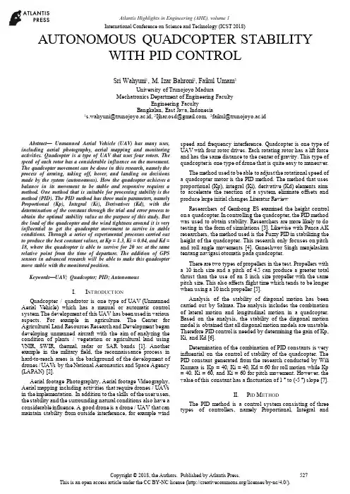
AUTONOMOUS QUADCOPTER STABILITYWITH PID CONTROLSri Wahyuni1, M. Izar Bahroni2, Faikul Umam3University of Trunojoyo MaduraMechatronics Department of Engineering FacultyEngineering FacultyBangkalan, East Java, Indonesia1**********************.id,2*******************,3*******************.idAbstract—Unmanned Aerial Vehicle (UAV) has many uses, including aerial photography, aerial mapping and monitoring activities. Quadcopter is a type of UAV that uses four rotors. The speed of each rotor has a considerable influence on the movement. The quadcopter movement can be done in this research, namely the process of arming, taking off, hover, and landing on decisions made by the system (autonomous). How the quadcopter achieves a balance in its movement to be stable and responsive requires a method. One method that is suitable for processing stability is the method (PID). The PID method has three main parameters, namely Proportional (Kp), Integral (Ki), Derivatives (Kd), with the determination of the constant through the trial and error process to obtain the optimal stability value as the purpose of this study. But the load of the quadcopter and the wind tightness around it is very influential to get the quadcopter movement to survive in stable conditions. Through a series of experimental processes carried out to produce the best constant values, at Kp = 1.3, Ki = 0.04, and Kd = 18, where the quadcopter is able to survive for 20 sec at the same relative point from the time of departure. The addition of GPS sensors in advanced research will be able to make this quadcopter move stable with the monitored position.Keywords—UAV; Quadcopter; PID; AutonomousI.I NTRODUCTIONQuadcopter / quadrotor is one type of UAV (Unmanned Aerial Vehicle) which has a manual or automatic control system. The development of this UAV has been used in various aspects. For example in agriculture. The Center for Agricultural Land Resources Research and Development began developing unmanned aircraft with the aim of analyzing the condition of plants / vegetation or agricultural land using VNIR, SWIR, thermal, radar or SAR bands [1]. Another example in the military field, the reconnaissance process in hard-to-reach areas is the background of the development of drones / UAVs by the National Aeronautics and Space Agency (LAPAN) [2].Aerial footage Photographty, Aerial footage Videography, Aerial mapping including activities that require drones / UAVs in the implementation. In addition to the skills of the user users, the stability and the surrounding natural conditions also have a considerable influence. A good drone is a drone / UAV that can maintain stability from outside interference, for example wind speed and frequency interference. Quadcopter is one type of UAV with four rotor drives. Each rotating rotor has a lift force and has the same distance to the center of gravity. This type of quadcopter is one type of drone that is quite easy to maneuver.The method used to be able to adjust the rotational speed of a quadcopter motor is the PID method. The method that uses proportional (Kp), integral (Ki), derivative (Kd) elements aims to accelerate the reaction of a system, eliminate offsets and produce large initial changes.Literatur ReviewResearchers of Gembong ES examined the height control on a quadcopter. In controlling the quadcopter, the PID method was used to obtain stability. Researchers are more likely to do testing in the form of simulations [3]. Likewise with Panca AK researchers, the method used is the Fuzzy PID in stabilizing the height of the quadcopter. This research only focuses on pitch and roll angle movements [4]. Guneshwor Singh menjelaskan tentang navigasi otomatis pada quadcopter.There are two types of propellers in the test. Propellers with a 10 inch size and a pitch of 4.5 can produce a greater total thrust than the use of an 8 inch size propeller with the same pitch size. This also affects flight time which tends to be longer when using a 10 inch propeller [5].Analysis of the stability of diagonal motion has been carried out by Salmaa. The analysis includes the combination of lateral motion and longitudinal motion in a quadcopter. Based on the analysis, the stability of the diagonal motion model is obtained that all diagonal motion models are unstable. Therefore PID control is needed by determining the gain of Kp, Ki, and Kd [6].Determination of the combination of PID constants is very influential on the control of stability of the quadcopter. The PID constant generated from the research conducted by Wili Kumara is Kp = 40, Ki = 40, Kd = 60 for roll motion while Kp = 40, Ki = 60, and Ki = 60 for pitch movement. However, the value of this constant has a fluctuation of 1 ° to (-5 °) slope [7].II.P ID M ETHODThe PID method is a control system consisting of three types of controllers, namely Proportional, Integral andInternational Conference on Science and Technology (ICST 2018)Derivative controllers. PID controller is one of the control methods that is often used in industrial control systems [8]. A. Proportional ControllerThe proportional controller has an output proportional to the magnitude of the error signal (the difference between the desired amount and the actual price). More simply it can be said that proportional controller output is a multiplication between proportional constants with input. Changes to the input signal will immediately cause the system to directly change its output by its constants.B. Integral ControllerThe integral controller functions to produce a system response that has a steady state error (zero steady state error). If a plant does not have an integrator element, the proportional controller will not be able to guarantee the system output with a zero steady state error. The use of an integral controller, the system response can be corrected, which has a zero steady state error.An integral controller has characteristics as well as an integral. The controller output is greatly affected by changes that are proportional to the error value. If the error signal does not change, the output will maintain the state as before the input changes.C. Derivative ControllerIntuitively, the oscillating system response is caused by several things. The dynamic process of a plant causes the response of a plant to not change immediately with a change in the control signal, but requires processing time. This time will make the control system experience delays to correct errors. This requires a controller that can predict errors from a system. Derivative controllers are generally used to speed up the initial response of a system, but do not minimize errors in the steady state. Derivative controller work is only effective in a narrow scope, namely in the transition period. Therefore the derivative controller is never used without any other controller of a system [8].III. BLOCK D IAGRAM S YSTEMThe block diagram in Fig. 1 is a system diagram consisting of several inputs which include the MPY-6050 type GY module in which there is an MPU-6050 sensor. Input in the form of slope data (gyrometer) and acceleration (accelerometer) becomes a reference for quadcopter balancing movements. The output of the system in the form of the speed value converted into a voltage value by ESC will drive a brushless motor that amounts to four. Brushless motor speed will be fully controlled using the PID method calculation. The ESC specification and brushless motor are adjusted to the load of the quadcopter.Input in the form of height sensor / wind pressure is a barometer and receiver from 2.4GHz radio control in the process on a different microcontroller. This section is as a medium for information on the height of the quadcopter when the quadcopter airs. Quadcopter communication with groundstation uses a bluetooth / wireless network module. The ground station receives altitude data from bluetooth to be able to control the 2.4Ghz transmitter radio control and provide information on the current mode status and height data on the personal computer.BMP-85MPU-6050Receiver (Rx)Arduino Nano Arduino Nano ESC 30A (4)Brushless MotorBluetoothPersonal ComputerTransmitterInputProcessOutputGround StationBluetoothFig. 1. Block Diagram SystemIV.F LOWCHARTA. General Flowchart Autonomous SystemIn Fig. 2 and Fig. 3 are general autonomous system flowcharts. Overall testing is done if the constant Kp, Ki, Kd is found to be optimal. This process is the whole process of moving the system on a quadcopter.Start Calibration Connecting ?NoYesCheck Bluetooth ConnectionSwitch ModeConnect PersonalComputerConnecting ?NoYesFig. 2. General flowchart of autonomous systems part 1Two bluetooth (master / slave) auto-pairing, both have ID identifiers, so bluetooth will be connected to bluetooth whose identification ID has been aligned. After the Bluetooth connection process is complete, the next step is to connect the personal computer to the system using a USB cable. Users can choose to use autonomous mode (automatic) or manual mode. When using autonomous mode, the system will run automatically according to the system design that has been made. The command to turn on the brushless motor is done by using a radio control transmitter. In the aeromodeling field, the process is often known as the Arming process. Then Take off is a quadcopter process to take off. Take off is done until it reaches a height of five meters. If the height has reached ten meters, the quadcopter will maintain height and stability for 30 seconds. Then the quadcopter will land / land slowly until it reaches the surface. But if the user uses manual mode. The manual program will be activated, all control systems are carried out manually by the user with a radio control device.Flowchart PID.Height = 10 m ?Arming/Motor ONMotor Off EndNoYes Take Off HoverLandingAutonomous Mode ON.?Start AutonomousProgram Start Manual ProgramYesNoCheck QuadcopterHeightControl by user (Transmitter)Fig. 3. General flowchart of autonomous systems part 2In Fig. 4 is a flowchart from the PID method. The PID method is used to maintain the stability of the quadcopter when moving. This method requires the main constants, Kp, Ki, Kd and Set point. The constant will be used to obtain an optimalsystem response. Determination of the value of Kp, Ki and Kd based on experiments by adjusting specifications on hardware. Starting with the reading of the gyro quadcopter value on the pitch, roll and yaw axis. The gyro data will be used as input for the calculation of the PID method. The output from the PID calculation will produce a PWM value for each brushless motor. The process will repeat the process until the error value is 0. The PID calculation is applied to the manual mode or autonomous mode.StartKp, Kd, Ki, Error, Last Error, SetpointRead MPU-6050 Gyro Value PID calculation Check ErrorError = 0EndYesNoPitch, Roll, Yaw PWM Motor BrushlessPWM motor1 = motor2 = motor3 = motor4Fig. 4. Flowchart PIDV.T ESTINGA.Bluetooth Distance TestingTesting is done in the open. This test aims to determine the range of the second Bluetooth communication. Because bluetooth communication is very important, the installation of the bluetooth module and the direction of the antenna on the bluetooth module must be considered very carefully. shown in Table 1.TABLE I.REACH TESTING DATAbluetooth communication, the average value of the range was 21.5 meters. If the Bluetooth range exceeds the range that has been entered in the test, the data communication will not be sent to the maximum or even thecommunication will be interrupted.B. Testing of Motor Lifting Power (Thrust)Lifting (thrust) testing is carried out on each brushless motor used on a quadcopter. Figure 5 is a graph of testing the lift using a 9540 (9 inch) propeller.Fig. 5. Motor Lift Power ChartC. Testing the PID MethodPID method is the main method used for quadcopter stabilization process. In testing this method, to get proportional (Kp), integral (Ki) and derivative (Kd) constants is done by trial and error. When the system is given a constant Kp, Ki, Kd is observed for quadcopter behavior. Testing the PID method is done in the test box. The test box is shown in Fig. 6.Testing to find a good system response is repeated. By observing the movement of the quadcopter in the stabilization process there will be some differences, including the response of the quadcopter stability to time. Here are some test results using Kp, Ki, Kd that have been done.Fig. 6. Stability TestFig. 7 is a test with a constant value of Kp = 1.3, Ki = 0.04 Kd = 5. The value of this constant is used continuously by the system. In addition to the response to steadystate fast enough, the response is not too visible to perform large oscillations. When testing, 200 sensor reading samples were taken with the assumption of data retrieval for four seconds.Fig. 7. Results of Testing the PID MethodVI. CONCLUSION AND FURTHER RESEARCHBased on the testing and analysis results that have been carried out in the research, the following conclusions are obtained:1. Quadcopter can perform optimal stability movementsusing the PID method. With a constant value of Kp = 1.3, Ki = 0.04 and Kd = 18.2. Delivery of altitude data sent via bluetooth communicationcan work well up to a distance of 21.5 meters.3. The initial position of the quadcopter during take off willaffect the shift of movement during flight.4.The type of propeller 1045 has a fairly large lift, but thetemperature of the motor when used is faster heat.5. The type of propeller 9450 tends to be more stable inmovement.6. Quadcopter tends to stay away from the initial coordinatepoint if the flight time is increased.From the results of the research conducted, for the next development, it is suggested that the following:1. Pay attention to the specifications of the quadcopter partused, especially in the specifications of the motor for lift strength and propeller type.munication for quadcopter and ground station shoulduse telemetry. So that the data transmission range can be carried out with a considerable distance and minimize frequency interference from outside.3.Adding GPS components, to determine the position /location when flying.4.Provides an electronic shock damper component that is inthe quadcopter to minimize the vibration generated by the four brushless rotors.5.Better mechanical design, to make it easier to implementthe control algorithm used.6.Pay attention to security factors during implementation.Addition of propeller protectors so that the propeller is safe when experiencing a system experiencing errors / crashes.7.When testing, you must first consider the state of the windspeed, this is to reduce the potential of the quadcopter carried by the wind (flyaway).A CKNOWLEDGMENTWe would like to show our gratitude to all our college and student in Mechatronics Department for sharing their wisdom during our research. This research was supported by Basic Mechatronic Laboratory.R EFERENCES[1]R. Shofiyanti, “Teknologi Pesawat Tanpa Awak untuk Pemetaan danPemantau an Tanaman dan Lahan Pertanian”, Informatika Pertanian, Vol.20, No.2, pp 58-64, 2011.[2]Aerostar TUAV : Drone Intai Andalan Skadron Udara 51 TNI AU.</aerostar-tuav-drone-intai-andalan-skadron udara-51-tni-au/> accessed on September 12th 2017.[3]G.E. Setyawan, E. Setiawan, W. Kurniawan, “Sistem KendaliKetinggian Quadcopter Menggunakan PID,” JT IIK, vol 2, no 2, pp 125-131, 2015.[4]P.A. Kusuma, A. Dharmawan, April, “Pengendalian KestabilanKetinggian pada Penerbangan Quadrotor dengan Metode PID Fuzzy,”IJE IS, Vol.7, No.1, pp 61-70, 2017.[5]I.O.G. Singh, “ Self-Navigating Quadcopter,” Int. J. Computer Sci. andInformation Technologies (IJCSIT), vol 6(3), pp 2761-2765, 2015.[6]Salmaa, “Analisa Kestabilan Gerak Diagonal pada Quadrotormenggunakan Kontrol PID,” Jurnal Ilmiah Matematika (MATH unesa), vol 3, no 6, 2017.[7]W.K. Juang, and L.L. Tung, “Pembuatan Mode l Quadcopter yang DapatMempertahankan Ketinggian Tertentu,” Jurnal Teknik Elektro, vol 9, no 2, 2016.[8]W.K. Juang, and L.L. Tung, “Pembuatan Mode l Quadcopter yang DapatMempertahankan Ketinggian Tertentu,” Jurnal Teknik Elektro, vol 9, no 2, 2016.。
分享无刷云台PID等参数说明以及调试教程参数说明:P,I,D - PID控制器设置,单独为每个轴P - 定义对干扰的响应。
越大,反应速度越快。
也可以解释为“增益”传感器信号之前,它会被传递给电机..如何调整:这个值从零慢慢增加,直至稳定的质量变得好。
太高的值可能导致系统自激(可见增加振荡)。
重要!如果从主框架的振动被传递到摄像机平台,它们可能导致简单的自我激励和不平衡。
在低频振荡的情况下,它们可以抑制通过增加D参数。
D的增加1 ..2个单位,如果将停止振荡 -你可能会进一步增加P。
D - 定义抑制反应。
它有助于防止低频振荡,但过高值可能会引入系统中的高频率的噪音的情况下,可能会增加振动。
尽量保持它尽可能接近零。
I - 定义反应的速度控制命令从接收器。
值给出非常低缓慢和平稳的操作员控制的反应,但也很缓慢的运动适当的地平线位置误差大的情况下。
高值让迅速移动相机和迅速返回到地平线,如有倾斜。
Power–定义对每个电机的输出功率。
设置从0到255,其中255 - 是最大的可用功率。
如何设置这个参数:过高的话会导致电机过热过低的话扭矩不够如果已经调过PID,还想再加power的话需要调小PIDInvert–定义了电机的旋转方向。
这是非常重要的,选择正确的设置。
那里自动检测。
要启动检测,设置P,I,D=0,设置功率上述建议(或一般值设置为100)。
级相机板水平(可能是不精确的,因为磁场矢量是随机的位置),然后按下自动按钮(位于附近设置反转)。
在校准过程中,相机将在小角度倾斜。
N.POLES -定义每个电机的极数(磁铁)。
此值大致在自动检测上面描述的校准程序。
如果检测到错误,手动:数一数磁铁电机(一般是14级)RC min.angleRC max.angle - 定义范围从最小的到最大角度的摄像头倾斜,从接收机控制。
逆控制,只需设置一个值大于第二个。
为例如,如果你想从地平线(0度)倾斜相机直降90度,min.angle=0,max.angle= 90(或90 ..逆为0)。
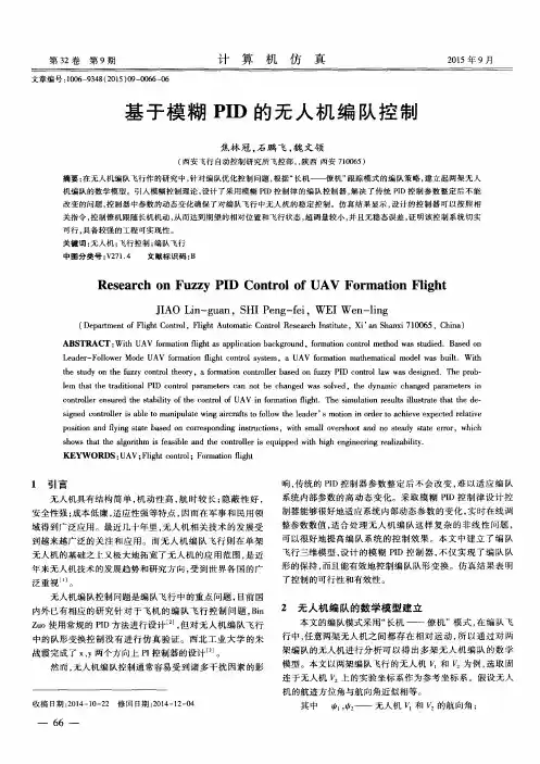
模糊PID算法的优化及其在无人机中的应用因结构简单、操作方便、机动性强、能垂直起降等特点,四旋翼无人机已成为工业界和学术界的热门研究课题。
但四旋翼无人机对环境变化极为敏感,使得对飞行姿态的精确控制难度较大,这对无人机飞控系统的设计者来说是一个严峻挑战,也使得飞行控制算法成为对四旋翼无人机控制的关键技术之一。
到目前为止,四旋翼无人机的核心控制方法仍然是PID控制,因为该飞行控制方法不需要对系统进行精确建模,只需根据系统误差,通过模糊规则调整控制器的参数,实现飞行控制。
基于国内外现有的研究成果,本论文对无人机PID控制器的设计进行了改进和测试,主要研究内容包括如下三个方面:1)对无人机姿态角修正方法的研究。
采用卡尔曼滤波算法降低传感器输出噪声对姿态角的干扰,从而提高姿态计算的准确性,通过MATLAB仿真以及实际试飞验证了卡尔曼滤波算法的有效性。
实验表明无人机姿态角的实际值和卡尔曼滤波算法估计值的仿真曲线高度相似,证实了该姿态角修正方法可显著提高无人机飞行控制系统输入值的可靠性;2)对无人机的姿态控制算法的研究。
设计方法结合经典PID和模糊控制的优点,通过选择合适的模糊规则建立参数自整定的模糊PID控制器,实现了PID参数的自行校正,增强了无人机对周围环境的适应性。
理论分析表明,模糊PID控制器控制精度和抗干扰能力均有所提升,但与传统PID控制器相比,稳态误差更大。
同时对无人机飞控系统动态特性及噪声来源进行了分析,对PID控制器进行特定应用环境下的优化,并利用MATLAB搭建出飞控系统的软件仿真平台,对优化后的控制器进行了效果验证;3)对无人机实验平台搭建的研究。
为验证优化后PID控制器对无人机实际控制的有效性,在论文第四章进行了无人机软硬件平台的搭建及实际试飞测试。
该章节描述了实验平台的硬件模块功能和驱动电路,软件设计部分给出了无人机控制的算法流程图和传感器采集数据及数据处理的算法流程图。
在实际试飞过程中,无人机的姿态信息通过无线回传至遥控器,遥控器通过串口可将姿态信息转发至PC机。
无人机三轴稳定云台的模糊PID控制郭炳坤,陈水利,吴云东,李渭(集美大学理学院,福建厦门 361021)[摘要]以无人机三轴稳定云台的内框作为研究对象,将自适应卡尔曼滤波算法与模糊PID控制算法相结合,提出了一种基于自适应卡尔曼滤波的模糊PID控制算法.经过Matlab仿真实验表明,相对于经典PID控制算法和模糊PID控制算法而言,该算法在无人机三轴稳定云台的控制上,不仅响应速度快、精度高,而且对控制干扰噪声和测量噪声也起到了较好的抑制作用.[关键词]无人机;三轴云台;自适应控制;模糊PID;模糊规则;自适应卡尔曼滤波Fuzzy-PID Control for UAV Three-axis Stable Pan-tiltGUO Bing-kun,CHEN Shui-li,WU Yun-dong,LI Wei(School of Science,Jimei University,Xiamen 361021,China)Abstract:With its research focus on the inner frame of UAV three-axis stable pan-tilt,combining the adaptive Kalman filter algorithm and the fuzzy PID control algorithm,the fuzzy PID control algorithm based on adaptive Kalman filter was presented.Through the simulation using Matlab,the results show that this algorithm have an more advantage than the classical PID control algorithm and fuzzy PID control algorithm in UAV three-axis stable pan-tilt.It has fast response and high precision.The system also has a good inhibitory effect on control interference noise and measure noise.Key words:UAV;three-axis pan-tilt;self-adaptive control;fuzzy-PID;fuzzy rule;Adaptive Kalman filter。
飞行器控制中的模糊PID控制策略研究飞行器控制是一项非常重要的技术,它对于安全、舒适的飞行和有效的任务完成起着关键作用。
控制飞行器的关键是要保持其飞行姿态的稳定。
而PID控制器是其中一种常用的控制策略,它可以通过反馈控制来将系统保持在目标状态,但是在某些情况下,PID控制器更难以处理,此时就需要使用模糊PID控制策略来解决问题。
一、PID控制器的优缺点PID控制器被广泛应用于飞行器控制中,其优点在于简单易用,拥有很好的干扰鲁棒性和稳定性。
在PID控制器中,输出产生的偏差经过比例、积分、微分三个环节得出控制量,使得飞行器能够保持目标状态。
虽然PID控制器具有这些优点,但是其在某些情况下也有缺点。
例如,PID控制器的响应速度较慢,容易因参数调节不当而产生过调和欠调等问题。
因此,它并非在所有情况下都能够产生理想效果。
二、模糊PID控制器的原理模糊PID控制器是一种PID控制器的改进。
它可以通过模糊逻辑控制的方法来对PID控制器进行优化。
模糊PID控制器的原理是把PID控制器的三个环节的控制误差和变化率转化为模糊度量,然后使用模糊逻辑控制器进行处理,最后再转化为输出量。
模糊PID控制器可以分为两个部分:一是前馈回路,用于测量控制器输入量的变化率;二是反馈回路,用于根据控制器输入量和目标输出量的误差进行调节。
三、模糊PID控制器的优缺点相比于PID控制器,模糊PID控制器具有更好的鲁棒性、稳定性和响应速度。
这是因为模糊PID控制器能够通过控制静态误差和变化率来调整输出量,从而实现更精确的控制。
此外,模糊PID控制器还能够自适应环境和参数变化,有效应对不确定性问题。
然而,模糊PID控制器相较于PID控制器也存在一些缺点。
首先,模糊PID控制器需要复杂的算法,并且调试参数是非常困难的。
其次,模糊PID控制器需要进行系统建模,需要消耗更多的计算资源。
四、应用举例模糊PID控制器的在飞行器控制中的应用,可以举出一些例子。
摘要交流伺服电机现广泛应用于机械结构的驱动部件和各种数控机床。
PID控制是伺服系统中使用最多的控制模式之一。
尽管传统的PID控制系统构造简单、运转稳定,但交流伺服电机存在非线性的、强耦合。
当参数变动或非线性因素的影响发生变化时,控制不能实时改动,不能满足系统高性能、高精度的要求。
结合模糊控制和传统PID控制成一种新的控制方法--模糊PID控制是解决上述问题的一种很好的途径。
模糊控制器不需要被控对象的数学模型,而是根据之前人为设定的控制要求设计用来控制的决策算法,使用此方式确定控制量。
模糊控制和传统PID控制融合的结果,不单具有模糊控制的高性能,还具备传统PID控制精准度高的长处。
本文对PID控制算法的原理和模糊控制算法作了简要的描述和比较。
指出模糊PID混合控制法,在误差很大时使用模糊控制,在不大时使用PID控制,在MATLAB软件中,对交流伺服系统的位置控制进行了仿真。
结果表明,该控制系统仿真结果与理论上差距较小。
关键词:PID控制;模糊控制;模糊PID控制器;MATLAB第1章绪论1.1 研究课题的任务本课题的任务是了解交流伺服系统,比较并结合两种控制的优点,结合成一种新的控制方式--模糊PID控制。
该控制法在系统输出差距大时采用模糊控制,而在差距较小时采用PID控制。
文章最后给出了模糊PID位置控制的MATLAB响应图,同时给出了常规PID控制下的效果图,并比较分析。
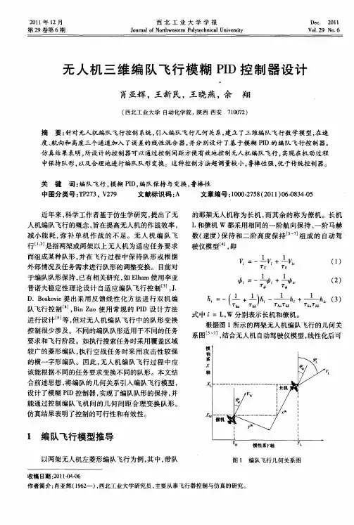
1.3 交流伺服系统工作原理相对单一的系统,其一般是根据位置检测反馈组成闭环位置伺服系统。
其组成框图参考图1-1内容[14]。
此类系统主要原理是对比输入的目标位置信号和位置检测设备测试的真实位置信号统计其偏差且使用功率变换器的输入端弱化误差。
控制量被信号转换和功率放大驱动,驱动伺服组织,促使误差不断缩减少,一直到最佳值。
(1)位置检测装置是此类系统的关键构成方面,完整系统的动态功能是否可以满足需求,关键的是位置检测传感器的科学选择以及精度。
PID是自动控制理论里的一种控制方法,PID的意思分别代表了比例、积分和微分。
具体是什么意思呢?解释如下:首先,我们有一个状态量,这个状态量在整个过程中,我们希望通过输入一个控制量,使这个状态量发生变化,并尽量的接近目标量。
比如,在航线控制中,状态量是飞机当前的飞行航向,目标量是飞机为到达目标点而应该飞行的目标航向,控制量则是我们对其进行控制的方向舵面,或横滚角度.我们通过调整方向舵面、横滚角度来控制飞机的当前飞行航向,使之尽量接近为压航线而应该飞行的目标航向。
那么我们如何给出这个控制量,比如给哪个方向的、多大的方向舵量呢?最简单的考虑,是按照当前航向与目标航向的偏差大小来决定给多大的方向舵量:方向舵量p = P *(目标航向–当前航向)。
这个方向舵量p,就是PID控制里的P部分,即比例部分。
那么,是不是只要有了P,我们的控制就完成了呢?实际上有了P,在大多数情况下,我们可以控制飞机朝目标量去接近,但可能会出现一些情况,比如,当飞机的安装有偏差(我们称之为系统误差),导致我们输出一个左5方向舵给舵机的时候,飞机才能直飞;当不给方向舵,即方向舵放在中位时,飞机会右偏。
我们想象一下这个时候如果只有P项控制会有什么后果:假设初始状态是飞机飞行航向和目标航向一致,按P输出飞机方向舵应该在中位。
而这时候,由于系统安装误差的存在,会导致飞机偏右,于是偏离了目标航向,然后P项控制会输出一个左舵,来修正航向偏差,刚开始的时候由于偏差量很小,输出的这个左舵也很小,于是飞机继续右偏,然后导致这个左舵加大,最终到达5,使飞机直飞,但这时候的飞行航向与目标航向始终存在一个偏差,这就是P的局限,无法修正系统误差。
于是I项积分控制就出场了.I项的输出这样定义:方向舵量i = I *(偏差和)。
偏差和是当前航向和目标航向的偏差,每计算一次累加一次,一直累加到上次的值,再加上这次计算时当前航向和目标航向的偏差。
即这个偏差和是跟以前的累积误差有关的。
模糊PID控制器的结果解析及其稳定性分析B.M. Mohan *, Arpita SinhaDepartment of Electrical Engineering, Indian Institute of Technology, Kharagpur 721302, India Received 14 July 2006; received in revised form 31 May 2007; accepted 10 June 2007 Available online 14 June 2007摘要:本文建立在三输入四输出变量模糊集的控制器基础之上对模糊PID控制器的解析。
该结构是基于对输入/输出为 ,L隶属度函数,代数积三角形准则、有界和三角形准则,Mamdami最小推理方式,中值法反模糊方式之上得出的。
文中的有界输入/输出稳定性的条件是基于小增益定理。
最后,以两个数值例子及其仿真结果来论证了最简模糊PID控制器的可行性和有效性。
1.介绍:由于传统PID控制器的简易性,鲁棒性好,对线性系统控制有效等优点,许多的工业控制仍采用这种控制方法。
本文图1给出了两种不同配置的PID控制器。
但由于其为线性结构,如果系统为高阶大时滞系统,非线性系统,没有精确数学模型的复杂模糊系统或是具有多个不确定因素的系统,传统的PID控制方法就无法非常有效地对其进行控制。
上个世纪90年代之前,大多数的模糊系统研究侧重在应用领域,而非理论研究。
直至1990年,研究人员才开始对模糊控制器进行结构解析及稳定性分析。
并如其他传统控制理论,针对一个对象,建立了模糊理论体系。
从模糊PI及模糊PD控制器与其对应传统控制器对上述复杂系统的控制结果的比较可看出其优越性。
由于模糊PI控制器比模糊PD控制器具有更好的优越性,模糊PD控制算法无法消除稳态误差。
但是,模糊PI控制器由于其自身的积分操作,在高阶系统时,并不能得到很好的控制效果。
第35卷第1期2015年2月弹箭与制导学报Journal of Projectiles,Rockets,Missiles and GuidanceVol.35No.1Feb2015基于模糊PID的无人机姿态控制器的设计*陈鹏,段凤阳,张庆杰,郑志成,肖伟(空军航空大学飞行器控制系,长春130022)摘要:针对某型无人机控制器在非线性条件下动态性能欠佳的问题,把容易实现、鲁棒性好的PID控制法与智能模糊控制算法结合,设计出自适应模糊PID无人机姿态控制器。
针对隶属度函数过度依赖专家经验的问题,运用遗传算法来优化隶属度函数,使控制效果达到优化。
经过仿真验证,所设计的控制器不但有PID控制精度高、易于实现的优点,还有模糊控制器超调小、动态响应快等优点,并且提高了跟踪和抗干扰性能,可以完成准确快速的姿态控制。
关键词:模糊PID;无人机;姿态控制器;优化隶属函数中图分类号:V249.1文献标志码:ADesign of UAV Attitude Controller Based on Fuzzy PIDCHEN Peng,DUAN Fengyang,ZHANG Qingjie,ZHENG Zhicheng,XIAO Wei(Department of Aviation Controlling,Aviation University of Air Force,Changchun130022,China)Abstract:The design of adaptive fuzzy PID UAV attitude control uses common PID control method and fuzzy control algorithm,since the membership function is over dependent on expert experience;genetic algorithm is used to optimize the membership function,the optimal control effect.The dynamic performance and robustness of the controller are greatly improved compared with traditional attitude controller,which is proved by simulation.Keywords:fuzzy PID;UAV;attitude controller;optimization of membership function0引言在科技发展的浪潮中,不断有新的控制理论被提出,而经典的PID控制作为最有效的控制方法还是占据了90%以上的应用领域[1],常规气动布局的飞机用PID方法来实现飞行姿态控制的应用亦是非常广泛[2]。
无人机云台稳定系统研究与控制算法设计无人机是一种主要通过无线电通信遥控或内置自主控制计算机飞行的飞行器,其广泛应用于民用和军事领域。
无人机在近年来迅速发展,使得已经初具规模的无人机市场成为了人们关注的热点话题。
然而,随着无人机技术的迅速发展,无人机云台稳定系统研究与控制算法设计也逐渐成为了无人机研究的核心问题之一。
一、无人机云台稳定系统研究1. 云台结构云台是无人机载荷运输和精确控制的关键部分,稳定性是云台的最基本要求。
从机械结构的角度来看,云台主要由云台控制器、切向式电机、云台支撑构架、旋翼舵机以及传感器组成。
旋翼舵机的重点在于云台的摆动,包括俯仰、横滚和偏航运动。
切向式电机负责控制云台的旋转方向,传感器则是获取无人机姿态变化的数据以便调整控制系统。
2. 控制系统控制系统也是无人机云台稳定系统的重要组成部分,以选择嵌入式系统作为云台的控制核心。
嵌入式系统自带高速处理器芯片,能够进行较为复杂的控制算法设计,同时也能进行数据采集和通信。
嵌入式系统不仅具有较高的计算速度和实时性,还能够应对不同运动场景下的运动轨迹,确保云台的稳定性。
控制算法方面的设计主要包括几种基本的优化控制方法,如PID控制和LQR控制。
二、控制算法设计1. PID控制PID控制全称为比例积分微分控制,是一种传统的控制算法,在工业控制中广泛应用。
PID控制按照误差的比例、积分、微分三个参数对功率进行控制,以达到稳定控制目的。
其中,比例环节是误差和控制结果的比例,积分环节是误差和控制位置的累计,微分环节是上次误差和上次控制结果的差。
PID控制方法具有计算简单、易于调整、实用性高的特点,常用于稳定运动系统。
2. LQR控制LQR控制全称为线性二次调节控制,是一种优化控制方法。
LQR控制不仅具有PID控制算法的特点,还能够优化系统的状态控制。
LQR控制利用最小二乘法以及状态控制理论,对误差进行优化控制。
通过调整状态的权重矩阵,不断求解控制器矩阵,优化控制系统的状态。
无人机三轴稳定云台的模糊PID控制
作者:郭炳坤, 陈水利, 吴云东, 李渭, GUO Bing-kun, CHEN Shui-li, WU Yun-dong, LI Wei
作者单位:集美大学理学院,福建厦门,361021
刊名:
集美大学学报(自然科学版)
英文刊名:Journal of Jimei University(Natural Science)
年,卷(期):2013,18(4)
1.陈水利;李敬功;王向公模糊集理论及其应用 2005
2.CHEN SHUI-LI;YUAN FANG;WU YUN-DONG A new hybrid fuzzy clustering approach to Takagi-Sugeno fuzzy modeling
2012(18)
3.MANDANI E H Application of Fuzzy algorithm for control of simple dynamic plant 1974(12)
4.MANDANI E H;ASSILIAN S An experiment in linguistic synthesis with a fuzzy logic controller 1975(01)
5.方圆;陈水利;陈国龙自适应粒子群算法的整定模糊PID控制器的参数优化[期刊论文]-集美大学学报(自然科学版) 2012(02)
6.王立新糊系统与模糊控制教程 2003
7.AHN K K;TRUONG D Q Online tuning fuzzy PID controller using robust extended Kalman filter[外文期刊] 2009(6)
8.PIEPMEIER J A;MCMURRAY G V;LIPKIN H Tracking amoving target with model independent visual servoing:a predictive estimation approach 1998
9.刘金琨先进PID控制MATLAB仿真 2011
10.白志刚自动调节系统解析与PID整定 2012
11.夏红;赏星耀;宋建成PID参数自整定方法综述[期刊论文]-浙江科技学院学报 2003(04)
12.王述彦;师宇;冯忠绪基于模糊HD控制器的控制方法研究[期刊论文]-机械科学与技术 2011(01)
13.ZhAN Z Y;TOMIZUKA M;ISAKA S Fuzzy gain scheduling of PID controllers 1993(05)
14.沈晔青;龚华军;熊琰自适应卡尔曼滤波在目标跟踪系统中的应用[期刊论文]-计算机仿真 2007(11)
15.白羽俊;徐晓苏;刘国燕神经网络辅助卡尔曼滤波技术在组合导航系统中的应用研究[期刊论文]-中国惯性技术学报 2003(02)
16.马静波;杨洪耕自适应卡尔曼滤波在电力系统短期负荷预测中的应用[期刊论文]-电网技术 2005(01)
17.张平;董小萌;付奎生机载/弹载视觉导引稳定平台的建模与控制 2011
引用本文格式:郭炳坤.陈水利.吴云东.李渭.GUO Bing-kun.CHEN Shui-li.WU Yun-dong.LI Wei无人机三轴稳定云台的模糊PID控制[期刊论文]-集美大学学报(自然科学版) 2013(4)。