T-Splines教程
- 格式:ppt
- 大小:15.10 MB
- 文档页数:45

Dynamo: Generative Modeling with T-Splines Ronnie ParsonsMode Lab@modelabnyc▪Global design and strategy to iterate and create in new and unimagined ways. www.modelab.is ▪Ppen-source guide to share the fundamentals of visual programming in Autodesk Dynamo. ▪Open-source searchable database for Dynamofunctionality. /Hi, I’m RonniePrimerDictionaryKey learning objectivesLearn quick and efficient workflows, using Dynamo and T-Splines, to generate structures, textures, and forms for rapid prototyping.At the end of this class, you will be able to:▪Create a parametric Dynamo Graph with T-Splines Nodes▪Extend Dynamo Functionality using the Package Manager▪Export a Dynamo T-Splines file for use in an External Application▪Create and Export a Dynamo T-Spline file for Rapid Prototyping▪Main class handout contains key information and workflows.▪Compiled from multiple chapters of the Dynamo Primer▪Datasets (Annotated for in-context learning)▪00.Getting Started▪01.Advanced ▪02.Going FurtherLab Handout(s)Lab handouts and datasets can be downloaded at:/v/au2016Dynamo:Open, Connected, CreativeWhat is Dynamo?▪Visual Programming Platform▪Compose Custom Algorithms▪Process Data and Generate Geometry▪Special kind of Geometry▪Combine many Surfaces as a Single Surface ▪Mathematically Watertight▪Minimal Amounts of Control Points What is a T-Spline?▪Open ▪Open-source design Tool▪Open▪Open-source design Tool ▪Connected ▪Stand-alone or Add-on▪Open▪Open-source design Tool ▪Connected▪Stand-alone or Add-on ▪Creative▪Visual Programming ▪Low-Poly Modeling ▪NURBS Compatability▪Open▪Connected▪Creative▪Generative▪Inspire Creativity▪Support ImaginationWhy Dynamo and TSplines?Getting Started with DynamoLaunching DynamoDynamo Start Page▪Ask▪Reference▪Code▪Samples▪Files > NewWhat’s in a Dynamo Program?▪Collection of Nodes▪Wired Together▪to Define Modeling InstructionsAnatomy of a Node1.Input Port2.Output Port3.Preview Bubble23Finding and Placing Nodes1.Search “Point”▪Use the Library Search to find nodes 2.Browse for “Point”▪Discover nodes in the Library Categories3.AddPoint.ByCoordinates ▪Click + Drag node to the Workspace 123Wiring Nodes to Build an Algorithm 1.Click on Output Port▪Node A2.Drag Wire to Input Port▪Node B3.Deleting Wires ▪Click on Port and Drag Wire Away 12Graph View VS Background 3D Preview 1.Switch Views▪Graph View▪Background 3D Preview2.Zoom Controls▪Independent Zoom Control 3.Pan View▪Click + Drag the Mouse 3 1 200.Introduction-To-DynamoBuilding Dynamo Graphs with T-SplinesWhy “Experimental” in Dynamo?01.TSpline-Pipe-From-Lines1.Create Two Lines2.Build a TSpline SurfaceTSplineSurface.BuildPipeBuildPipes from lines02.TSpline-Pipe-From-List1.Create Three Lines2.Create One Circle3.Build a TSpline Surface▪TSplineSurface.BuildPipe▪Convert to BRep▪Export Surface▪TSM▪SAT BuildPipes from a list03.TSpline-Primitive-Speedform▪Create Quadball▪Scale Quadball▪Display Topology Data▪Create Symmetry Axes▪Extrude Quadball Faces▪Crease EdgesScaled Quadball with Extrusions and Creased EdgesAdvanced Workflows Attractors, Image Sampling04.TSpline-Crease-Bevel-Edges▪Import SAT▪Convert NURBS to TSpline▪Crease Edges▪Bevel Edges▪Translate Vertices by AttractorCreased and Beveled edges in one direction.05.TSpline-Surface-From-Lines▪Import SAT Surface▪Import Image File▪Use Brightness to Offset▪Create Quads on Surface▪Scale Quads▪Based on an Attractor▪Create Lines Between▪TSpline from Lines Build Tsplines from LinesExtending Dynamo with Packages▪“MeshToolkit”▪“MapToSurface”▪Install Current VersionOnline Package Search WindowSearch for a Package…Dynamo Packages07.TSpline-Geometry-Replicator-Mapping▪Dynamo Packages▪MapToSurface▪MeshToolkit▪Exporting TSpline Files▪TSM (Mesh File)▪Single TSpline ObjectNext StepsThe Dynamo Primer Dynamo Dictionary▪Your class feedback is critical. Fill out a class survey now.▪Use the AU mobile app or fill out a class survey online.▪Give feedback after each session. ▪AU speakers will get feedbackin real-time.▪Your feedback results in betterclasses and a better AU experience. How did I do?Lab handouts and datasets can be downloaded at:/v/au2016In case you missed themhttp://modelab.is/Autodesk is a registered trademark of Autodesk, Inc., and/or its subsidiaries and/or affiliates in the USA and/or other countries. All other brand names, product names, or trademarks belong to their respective holders. Autodesk reserves the right to alter product and services offerings, and specifications and pricingDynamo Web ExperienceSend to Web (Dynamo Studio)Dynamo Graph, formatted for “Send to Web”curated version of your workthat is web accessiblethrough an online link.Customizer View1.Menu Bar3.3D PreviewCustomizer ViewCustomizer View。
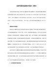
前言T .Splines 2.0 For Rhino 经过了不断改进,终于推出了2.0版本,相比之前的版本,在功能﹑稳定性﹑操作便捷上都有了不少的改进并新增加多个工具,现在的2.0版本应该说应用于建模流程上已经是成熟了。
值得一提的是T-Splines For Rhino(以下简称TS)对对象的编辑操作方式有了较大的进步,以至用户使用起来有感觉比Rhino 的还强些的感觉呢~! 本海豚模型是根据官网的相同内容的视频教程制作而成,特地将其过程摘录下来,并提供各个建模阶段的文件供阁下参考。
总结一下,TS 的建模方式可分为6种,分别为:1. 以几何体为基础,通过编辑,细分,挤出,加减控制线等方式生成所需要的曲面外形2. 以多段性组构面外形线框,生为TS 曲面3. 以曲线放样(_tsLoft 命令)得到TS 曲面4. 以曲线组成的外形线框,由蒙皮(Skin)生成一整体的TS 曲面5. 以NURBS 曲面为基础,过转换TS 曲面再进行加工6. 以输入的mesh 模型为基础,转换为TS 曲面再进行编辑,加工海豚模型是采用第1种的建模方式,也是TS 中最为直观便捷的建模方法,因此可以作为TS 入门练习开始建模前开始建模前的热身的热身的热身运动运动:点击TS 工具栏中的进入TS 选项网格显示精度设置:如果你的电脑配置不错,可以将设置值设得高点,数值越大,曲面显示越光滑,一般情况下,设置为中等即可有较佳的视觉效果了另外,为更直观地进行拖拉控制点操作,建议勾选“控制点示在曲面上”的项目,两者的分别如图T .Splines 2.0强大的操纵器 Manipulator在2.0版本中提供给我们一个编辑模型的利器——操纵器这个操纵器分为四个功能,移动,缩放,旋转,支点操作;分别对模型的点,边,面,整体进行操作(下图为常用的三个操作方式)它为我们提供了自由和精确的编辑方式当选取了模型的点,边,面,整体后,操纵器会出现移动 缩放 旋转点选操纵器中各X ,Y ,Z 手柄后就可以进行单个轴向推拉,缩放,旋转的操作,如果想三个轴向同时联动怎么办呢?呵呵~~TS 已经为你想好了,缩放,旋转的三个手柄间有个小圆片,移动时,就能实现联动操作了,在透视图中可实现三个轴向联动。
T―Splines在工业设计中的应用T―Splines在工业设计中的应用关键词:T-splines 工业设计计算机辅助设计摘要:本文主要讲述网格建模插件T-Splines在工业设计中的应用,为工业设计的曲面创建提供了新的曲面建模方法。
并详细展示T-Splines从实体创建曲面、从线创建曲面和从输入曲面创建曲面的曲面案例效果。
作为网格曲面、NURBS曲面的下一代的曲面建模技术,必将有广阔的发展前景。
一、背景在工业设计中,尤其是工业产品设计中,三维设计表现具有非常重要的作用,快速、准确将创意表现出来是工业设计师必备的能力之一。
目前典型的NURBS曲面建模软件Rhino因其曲面功能强大、操作方便、快速入门受到广大工业设计师和学生的欢迎。
Rhino是由美国RobertMcNeel公司于1998年推出的一款基于NURBS(Non-Uniform Rational B-Spline)非均匀有理B样条曲线为主的三维建模软件。
是一款强大的专业3D造型软件,Rhino非常适合于工业产品设计早期阶段的设计方案快速表现,在产品设计领域具有广泛的应用。
二、T-splines简介T-Splines作为Rhino的一个插件,与Rhino紧密集成,帮助设计师缩短其设计时间,完成那些以Rhino处理起来十分枯燥或困难的任务,并且可以在细分表面建模程序与Rhino之间切换,帮助设计师轻松创建和编辑用于设计和制造的有机曲面。
T-Splines是Autodesk公司开发的一种具有革命性的崭新建模技术,它结合了NURBS和细分表面建模技术(3dsmax采用多边形建模技术)的特点,虽然和NURBS很相似,不过它极大地减少了模型表面上的控制点数目,可以进行局部细分和合并两个NURBS面片等操作,通过对控制点的“推和拉”快速完成三维模型的创建,在建模操作速度上有质的提升。
T-Splines是NURBS和细分曲面的扩展,填补了流行的多边形建模功能和传统NURBS建模之间的空白,是继网格曲面、NURBS曲面的下一代的曲面建模技术,是首款真正意义上可以替代基于NURBS建模的软件。
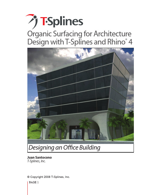
Organic Surfacing for Architecture Design with T-Splines and Rhino® 4Designing an Office BuildingJuan SantoconoT-Splines, Inc.© Copyright 2008 T-Splines, Inc.The T-Splines for Rhino plugin brings architectural designers new ways to easily create andmodify organic designs. Designing freeform objects can be difficult when working with tra-ditional CAD software. T-Splines and Rhino 4 offer an easy way to create smooth, gap-freefreeform models for architecture.In this tutorial, anything in Blue is a Rhino command, while anything in Red is a T-Splines com-mand. Type these commands in the command line of Rhino to run them.The best way to read this tutorial is by looking at the 3d model at the same time. You can fol-low the model’s progress by selecting the different layers in the file. The model can be down-loaded at .1Creating the control polygonReference drawingsThe design intent of this project is to combine natural, organic elements with crisp, man-made components. The building architecture suggests a flowing transition from the earth into thecolumns, which gradually give way to the sharp angles of a functional office building. At thebeginning of the project, I made some hand drawings to explore the general concept of thebuilding, then I did some 2d modeling of the general structure in Rhino as a reference for the 3d model.Concept hand drawingsGenerating the control polygonTo get the shape of the building I used the tsControlPolygonToSrf command, which allows a complete complex surface to be generated just by blocking out its basic geometry with a control polygon. Below, you can see a basic control polygon, which is just a bunch of line seg-ments, connected together, which describe the final surface.What to do?Building a control polygon can some-times be difficult; where do you start?How do you know how the surface willreact?For this kind of shape, one approach is tofirst lay out profiles, and then make con-nections between them. In this case, theprofiles are in red, while connections arein green.ProfilesConnection linesSome tipsBy adding extra profiles and connec-•tion lines (blue) situated near each other, you can decrease smoothness in particular areas. I employed this technique to tighten the surface where the smooth columns meet the sharp box structure.You can think of the profile lines as contours, •and the connection lines as rails that show how the surface isoparms will flow between the con-tours. If you keep this principle in mind, it may help you set up your next project as well.One way to preview what the approximate cur-•vature the surface will be is to make a Curve by snapping on all the points of a particular rail.Extra profilesExtra connection lines Approximation of the curvature on a par-ticular connection rail.1. Start by creating the most complex part of the control polygon: the area where the smooth columns meet the sharp main body of the building. First, use _Rectangle to draw the base part of the building.2. Now you need to connect all these rectan-gles by using _Line to create “faces.” It´s impor-tant to keep in mind that faces with four sides produce the best surface results, however, having too many control polygon lines makes the resulting surface tighter. So, for this project, a mix of 4-sided faces with 5/6-sided faces will get the desired result.How to do it?Now that you know in general how the control polygon will look, it is time to model it. There are many ways of doing this, I will show just one.3. It’s time to transform this flat control poly-gon into 3d.First use the _tsScriptExtrudeControlPoly-gon command on the interior rectangles to extrude them 7 meters in the negative “Z” direction (-Z).4. Next, run the _tsSplitCurves command on all the green and red line segments. Then, with _tsScriptExtrudeControlPolygon , extrude the outer rectangle +Z (0.5 meters). You will need to select each segment in the rectangle indi-vidually before extruding it, since the rectangle is now split. This extrusion will yield a tighter transition between the columns and the upper part of the building.1234Extrude -Z Extrude +Z5. Select all the segments and run _PointsOn tomake all control points visible. Then select all upper points (shown) and using _tsManip (the manipulator) scale +X to achieve the same angle as the reference drawings. (Make sure you mar-quee select each point by dragging a box around it, because each “point” actually contains several coincident points). This needs to be done on both the front and side view.6. Now it is time to draw the upper part of the building. Use the reference profiles to draw a simple rectangle for the roof. Then, use Rhino’s Snap End option to connect the roof rectangle tothe red control polygon corners.Now you have the input control polygon lines that you need to generate the T-Splines surface. You just used a reference drawing to construct a control polygon, which can now be used to generate a surface that will describe the entire building, giving you flexibility to edit any control point in the future to adjust the shape.Maybe, at first, it seems complicated to create the control polygon, but realize that you will achieve a very complex surface, without drawing even a single curve, just all straight line segments. This can be a great advantage to an architect who may not be proficient with 3d curves.5-side 5-frontScale +X5-detailScale to match angle6Face layoutThis helps you define the topology of the surface. The command will automatically try to define the topology, but won’t always guess right, so you need to provide input by selecting and deselecting the faces until you get the desired surface. There is an option that you can change in order to partially automate this: use MaxAutoFace: 6 on the command bar options.Add creasesUse the creases option and select the segments that will have a sharp crease on the final surface. Use thepreview option constantly to check it out.Once you have finished, hit ok.The result is a surface that can be completly editedby its control points.tsControlPolygonToSrf commandSelect all the curves and run the _tsControlPolygonToSrf command.Inside the _tsControlPolygonToSrf command, the options dialog box will appear.2Click on the bottom of the column faces. You need open surfaces on these parts.Inspect the model until you get the right topology.Add CreasesClick on faces to deselectFinal topologyCreasesCommon mistakes There are two common mistakes when using the tsControlPolygon-ToSrf command, so if something goes wrong, it can almost always be fixed by checking these two things:1.Duplicate lines. These are very common when modeling control polygons, and must be deleted (you can easily do this by running the SelDup command and then deleting the lines that are selected).2. Unsplit lines.These can prevent the surface from being generated as you desire. To fix this, before run-ning the command, use _tsSplitCurves to be sure that all line segments are separate from each other.Maybe the isoparms on the flat faceslook strange, but they are created as thegeometry from the columns blends to thebox. We could lay out the control polygondifferently to have more orderly isoparmshere, but I chose this way because it is easyto teach.T-Splines surface3Editing the T-Splines surfaceOne of the advantages of using T-Splines for this kind of organic structure is that often, con-stant manual editing is necessary to attain just the right shape, and T-Splines gives us the posi-bility of modeling very complex surfaces with minimal and completely editable control points.Adjust column curvatureIn order to get a concave look on the columns Points selectedarea, select all the mid-points and using the _ts-Manip, scale in 3 axes (by grabbing the middlecube). Use your reference profiles to achieve theproper curvature.1. Select the indicated points in the front view.2. Scale. For better control, you can alternativelyscale in 1 axis on the front or side view to keepbetter control on the curvature.Scale -XAdjusting ceilingYou can see that the surface seems too tightwhere the columns meet the ceiling. You justneed to edit some points in order to get asmoother transition.Just select the control points that influence the“corridor” part of the surface. (In the file there isa sublayer called PointsToSelect that shows youwhich to select.)Use _tsManip command to move them -Z for 2meters. This is enough to get a smoother look.Some changesYou can also create creases with the _tsCreasecommand. In this case I realized that having suchsmooth curvature where the columns met themain building wouldn’t be desirable, so I addeda crease.Run the _tsCrease command and select all thesegments that comprise the row.Keep sharpness option on 1 (perfectly sharp)and Insertion type option on simple. Hit ok.Move -ZPoints to moveBefore AfterCrease segmentsCreasing columnsTo give the design a slightly more industrial look on the columns, add some creases here, too. However, since there are star points nearby, you need to first add some more ge-ometry. As a rule of thumb you need 3 segments of separa-tion between the crease and the star point. In order to get this geometry, run the command _tsInsertPoint and click to add geometry at the star point area on one of the columns. Repeat this until you have enough segments (3 times). Re-member to do it on each star point that influence a crease.Now it is time to crease.Run the _tsCrease command and se-lect the segment. The tool will crease the selected segment, leaving adjacent segments partially creased as the crease gradually dies out into the smooth surface.Repeat this on the other corner columns.Star PointSegment to crease1234123oCreasing the segmentAdjusting column baseTo emphasize the strength of the col-umns, scale some control points.First, select the points that comprisethe inner faces of the columns (Frontview) and Run _tsManip.Scale them -X.Keeping the same points selected,switch to side view and Run _tsManip.Scale them -Y.Now you have the final T-Spline surface!You can edit the control points or convert the sur-face to NURBS (_tsConvertToRhinoSurface) and useany of the native Rhino tools on it.For a smoother surface around the star points, turnthe _tsSetStarSmoothness command with a valueof 3 or 5.The T-Splines model is an accurate description ofthe geometry, so it can be used not only for visual-ization, but also for production. For example: Extract section curves.Analyze the surfaceTrim to extract differentparts of the curvature.Scale -XScale -YPAGE 11T •Splines Download a free trial of T-Splines for Rhino at Some project renders and images.Good luck!Juan Santoconojuan@。
课程按照由浅入深的教学顺序划分为如下7个阶段:1.造型方法和技巧本部分以详细介绍各种建模工具的使用方法为主,并以丰富的范例围绕这些建模工具介绍曲面造型方法中惯用的技巧和经验,其中包括诸多建筑设计中常见的造型范例。
通过这部分的学习学员对曲面造型工具可以有一个全面的了解和掌握。
2.建筑造型专题研讨本部分以专题的形式对建筑设计中的一些特定的造型设计阶段以专题的形式进行深入的探讨,例如:. 如何利用基本拓扑结构设计造型多变的贴皮效果. 膜结构的造型设计和材料的摊平切割方法. 如何将整体的玻璃幕墙结构摊平配合图纸和加工. 曲面钢结构的造型设计和结构拆分方法. 曲面造型的贴皮技法综合技法. 曲面造型的玻璃幕墙制作流程对于这些曲面建筑设计中经常会遇到技术难点的部分我们将会演示这些问题是如何产生的,并且如何利用各种有效的手段去避免和解决这些造型难题。
3.综合案例本部分是前两个阶段的基础上进行的综合练习,我们特别准备了多个从造型设计方向和造型方法都完全不同的实际案例作为范例,并且这些案例都是已经建造出的成功的经典案例,从这些建筑造型的外形特点入手进行分析,了解如何把握制作难点,制定制作方案,并一步一步引导学员亲自制作出这些经典案例。
学员可以从这部分学习到如何在实际的建筑设计案例中灵活和综合的运用各种曲面建模工具和造型技巧。
4.T-Splines 建筑曲面教学T-Splines 是由 T-Splines 公司领导开发的一种具有革命性的崭新建模技术,它结合了Nurbs 和细分表面建模技术的特点,虽然和Nurbs很相似,不过它极大地减少了模型表面上的控制点数目,可以进行局部细分和合并两个Nurbs面片等操作.使你的建模操作速度和渲染速度都得到提升5.PanelingTools 建筑表皮教学Rhino 原厂为所有建筑设计师提供的镶板/嵌板制作工具,PanelingTools 可以帮助你在各种复杂曲面(包含所有NURBS曲面与T-Splines曲面)上创建各种不同的镶板,从而得到形式各异的表皮与膜结构。
Product Surfacing with T-Splines and Parametric Modeling ToolsFACULTY INDUSTRIAL DESIGN – WAYNE STATE UNIVERSITY****************.studioKuhnen.deClaas Eicke KuhnenA little bit about myself:Undergraduate degree in Color Design for Product and Graphic Design MFA in 3D Studio for Jewelry and Digital Animation I always have been very curious about 3D in general Faculty Industrial Design at Wayne State UniversityResearch Assistant in BioMedical Engineering studioKuhnen LLCFocus: Digital design tools and workflows for product development andrapid digital prototyping combining different programs into on cohesivedesign approach.BackgroundClass summaryDescription:This class will demonstrate a workflow that uses the T-Splines Module in Fusion 360 software to create NURBS-like surface patches based on existing sketches and sculpting the desired surface flows via CV direct modeling.The resulting boundary representations (BREPs) can be further manipulated with solid and surface modeling tools inside Fusion 360’s parametric timeline.The class will also focus on proper T-Spline mesh topology to improve resulting BREP patch layout quality.Key learning objectivesAt the end of this class, you will be able to:▪Create T-Splines surfaces via sketches and primitives▪Sculpting T-Spline surfaces and maintain proper topology layouts▪Use T-Splines with other modeling tools in the parametric timeline▪Understand best practices and parametric surfacing strategies▪Understand how to exchange data with other 3rd party applicationsNURBS vs T-Splines▪Precise▪Curvature graph▪Single 4 sided patch▪Poly surface for complex topology▪Insert isoprams or change degree while keeping the shape▪Cannot refine density locally (only on complete patch)▪To round edges fillet command has/ can to be used ▪Precise▪Curvature graph (with limitations)▪Single 4 sided patch and NGons▪Single surface for complex topology ▪Insert loop-cuts while keeping the exact shape▪Insert edge on a face where needed for local density change▪Fillets can be sculpted via edge loops and mesh topology on the fly▪Advantage:▪Clean light weight geometry▪Control over patch layout▪Disadvantage:▪Very labor intensive for smooth shapes▪Requires perfect profile layouts▪Design adjustments require manual sketch and surface re-alignments ▪Advantage:▪Incredible easy to sculpt▪Organic flows can be modeled with irregular topology layouts▪Disadvantage:▪Patch layout can get messy when T-Splines mesh count is high▪Achieving smooth curvature is harder than blending between NURBSsurfacesConclusionThink about T-Splines like NURBS:▪Think and treat T-Splines like NURBS that combines the best for NURBS andpolygon modeling together into one workflow▪Maintain slim mesh density like in a NURBS sculpting workflow▪But make use of mesh topology freedom from Sub-D modeling▪Then you have NURBS CV cage editing in Fusion 360Excited?So lets get started!▪Your class feedback is critical. Fill out a class survey now.▪Use the AU mobile app or fill out a class survey online.▪Give feedback after each session. ▪AU speakers will get feedback in real-time.▪Your feedback results in betterclasses and a better AU experience. How did I do?More Questions? Visit the AU Answer Bar ▪Seek answers to all of your technical productquestions by visiting the Answer Bar.Wednesday; 8am-4:30pm Thursday.▪Located outside Hall C, Level 2.▪Meet Autodesk developers, testers,& support engineers ready to helpwith your most challengingtechnical questions.Shape the future of Autodesk▪Connect one-on-one with product managers, designers, and researchers at the Idea Exchange.GoPro Sweepstakes.▪Open daily – Sessions average 20 minutes.No appointment necessary. Walk-ins welcome!▪Located outside Hall C, Level 2.▪View my contributor profile at AUonline for a list of all my classes.▪Learn more about me and see allmy contributions to Autodesklearning.▪Activate your own profile and startcontributing.▪Complete your profile while at AULas Vegas and Autodesk will makea donation on your behalf.See all my AU classes in one placeAutodesk is a registered trademark of Autodesk, Inc., and/or its subsidiaries and/or affiliates in the USA and/or other countries. All other brand names, product names, or trademarks belong to their respective holders. Autodesk reserves the right to alter product and services offerings, and。