气缸体设计说明书
- 格式:doc
- 大小:2.40 MB
- 文档页数:35
![机械制图毕业设计plc气缸毕业设计说明书[管理资料]](https://uimg.taocdn.com/fffb212049649b6649d7476b.webp)
XXXXXX大学毕业设计说明书学生姓名:LZW 学号:20XXXXXXX 学院: XXXX学院专业年级: 20XX级XXXXXXXX题目:气缸盖生产线生产节拍的调节装置设计指导教师:XXX评阅教师:20XX年XX月摘要本次毕业设计的课题是关于气缸盖生产线上生产节拍的调节装置的设计。
首先第一部分对生产线上作为输送工具的辊子输送机作了简单的概述;接着分析了限力式辊子输送机的选型原则及计算方法;然后根据这些设计准则与计算选型方法按照给定参数要求进行选型设计;接着对所选择的输送机各主要零部件进行了校核。
GTZ 6型辊子输送机由三个主要部分组成:辊子,机身包括机架、支腿和调节脚,驱动装置。
最后简单的说明了输送机的安装与维护。
第二部分主要分析一下气缸盖生产线上生产节拍的控制装置。
根据课题要求,采用的气动和电气联动的控制方式,首先选择满足要求的气压缸,从而形成对气缸盖进行行程夹紧的气压传动系统,然后利用PLC程序控制下的光电接触器对生产节拍发出的调节指令来控制气缸盖得加工行程。
目前,利用机电一体化系统来对生产线上的生产节拍进行调节技术已经日趋完善和成熟,这种控制方式具有的快速动作、准确定位、生产自动化的突出特点正逐渐的被越来越多的应用和发展。
然而不可否认的,目前我国在该项技术上与国外先进水平相比仍有较大差距,国内在设计制造的过程中存在着很多不足。
本次气缸盖生产线生产节拍的调节装置设计代表了设计的一般过程, 对今后的选型设计工作有一定的参考价值。
关键词:限力式辊子输送机;选型设计;主要部件;PLC;气缸Abstract:The issue of graduation is on the cylinder head production line beat of the adjustment device design. First of all, the first part of the production line as a transportation tool, roller conveyors briefly summarized; then analyzed the limited force-type roller conveyor principle of selection and method of calculation; then calculated based on these design criteria and selection method in accordance with the given parametersselection of design requirements; then choose conveyor on the main components were checked. GTZ 6-type roller conveyor consists of three main parts: rollers, including the fuselage frame, legs and adjust the foot, drive. Finally a simple description of a conveyor installation and maintenance. The second part of the main analysis of the cylinder head production line beat the control device. According to requirements of the subject, using the pneumatic and electrical control linkage method, the first choice to meet the requirements of the pneumatic cylinder to form the clamping stroke of the cylinder head to the air pressure drive, and then under program control using PLC optical beat contactor issued on production regulation orders to control the processing of the cylinder head must travel. At present, the use of mechatronics system to beat on the production line to adjust the production technology is maturing and mature, this control method has a fast movement, accurate positioning of the prominent features of automation is gradually being more and more applications and development. However, no denying that our country in the technologically advanced level is still far, the domestic manufacturers in the design process there is much to be desired.The cylinder head production line beat the adjustment device design represents the general process of design, selection of design work on the future of some reference value.Keyword:Limit power-type roller conveyor;type design;main parts;PLC;cylinder。
1.前言1.1 本课题的意义S295柴油机以其设计紧凑,启动轻便,维修简便,技术经济指标先进,能为手扶拖拉机、水泵、电站、运输与多种农副业加工机械和设备作配套动力,在工农业生产中得到广泛的应用。
机体是柴油机的一个重要零件, 首先要对柴油机气缸体进行工艺设计。
要对柴油机气缸体零件进行工艺性审查,确定零件的结构特点,加工材料,加工表面与其要求等。
本设计的柴油机气缸体主要包括两个部分:工艺设计部分和工装设计部分。
工艺设计主要是对柴油机气缸体的加工工艺路线进行设计,工装设计部分则是对钻夹具进行设计。
随着现代工业生产水平的飞速提高,设计新产品、新加工工艺路线,实现现代化,提高生产率,是当前生产中的迫在眉捷的任务。
在设计工作开始之前,老师带领我们参观了机床厂生产流水线,让我首先对生产柴油机气缸体有了感性认识。
在参观的过程中,老师认真地给我讲解了其加工过程和生产方式,分析了各部件的功能特性,避免了我在以后的毕业设计过程中的盲目性。
1.2 国(外)发展概况与现状柴油机的开发焦点已由传统的优先考虑经济性、可靠性和耐久性逐步转为目前的优先考虑环保的要求,即以优先保护好人类赖以生存的地球环境为出发点去考虑采用何种技术,去评价其先进性。
优先考虑柴油机排放、噪声对环境的影响问题,与过去相比也有不同,就是在满足目前对排气污染物、颗粒排放与噪声的限制要求时,不再以牺牲经济性、动力性和比质量等为代价,而是在达到上述目标的同时使产品具有可竞争的商业价格。
欧洲一些公司近年或稍后将继续推出能满足环境要求的百公里油耗为3L的柴油机。
当前和将来一个时期车用柴油机技术的发展趋势突出表现在如下几个方面:A.进一步优化燃烧系统,特别重视开发和选择喷射系统Perkins公司的Ouadram 燃烧室、日野公司的HMMS燃烧室,小松公司的MTEC燃烧室与五十铃公司的四角形燃烧室等,都在试验开发阶段,其基本特点是由一个中央涡流与四周的微涡流使空气燃料快速而充分地混合,并配合以合适的燃油喷射系统。
佳木斯大學机械设计制造及其自动化专业(卓越工程师)说明书题目单杆活塞式液压缸的设计学院机械工程学院专业机械设计制造及其自动化(卓越工师)组员曾瑶瑶、王健跃、杨兰、沈宜斌指导教师臧克江完成日期2016年6月佳木斯大学机械工程学院目录设计要求 (II)第1章缸的设计 (1)1.1 液压缸类型和结构型式的确定 (1)1.1.1结构类型 (1)1.1.2局部结构及选材初选 (1)1.2液压缸主要尺寸的确定 (2)1.2.1 液压缸筒的内径D的确定 (2)1.2.2 活塞杆直径d的确定 (3)1.2.3 缸筒长度l的确定(如图1-3) (3)1.2.4 导向套的设计 (4)1.3活塞及活塞杆处密封圈的选用 (4)1.4缓冲装置设计计算 (5)第2章强度和稳定性计算 (7)2.1缸筒壁厚和外径计算 (7)2.2缸底厚度计算 (7)2.3 活塞杆强度计算 (7)致谢 (8)参考文献 (9)设计要求设计单杆活塞式液压缸;系统压力:10MPa;系统流量:100L/min;液压缸行程:450mm;速度:30mm/s;液压缸输出力:5000N;油口尺寸:M24*1.5,且两油口尽可能在缸筒的缸底侧;液压缸与外界联接方式缸底固定,活塞杆为耳环联接。
第1章缸的设计1.1 液压缸类型和结构型式的确定1.1.1结构类型1、采用单作用单杆活塞缸;2、液压缸的安装形式采用轴线固定类中的头部内法兰式安装在机器上。
法兰设置在活塞杆端的缸头上,内侧面与机械安装面贴紧,这叫头部内法兰式。
液压缸工作时,安装螺栓受力不大,主要靠安装支承面承受,所以法兰直径较小,结构较紧凑【1】。
这种安装形式在固定安装形式中应用得最多。
而且压力机的工作时的作用力是推力,则采用图1-1的安装形式。
图1-1安装形式1.1.2局部结构及选材初选1、缸筒的材料采用45号无缝钢管(如图1-2);图1-2缸筒的设计2、缸底的材料:采用45号钢,与缸筒采用法兰连接【2】;3、缸盖:采用45号钢,与缸筒采用法兰连接;4、缸体与外部的链接结构为刚性固定:采用头部内法兰式连接;5、活塞:活塞采用铸铁;6、活塞杆:活塞缸采用45号钢,设计为实心;7、排气装置:在缸筒尾端采用组合排气塞;8、密封件的选用:活塞和活塞杆的密封件采用O形密封圈加挡圈【3】。
重载型止动气缸RS2H系列(φ50~φ80)安全注意事项 P.2 1.规格 P.4 1-1.气缸规格1-2.单作用、双作用内置弹簧型弹簧力1-3.标准行程1-4.气缸重量2.机种选定 P.53.设置方法 P.8 3-1.关于使用空气3-2.配管3-3.使用环境3-4.使用注意事项3-5.传送方向和配管位置关系的方向变化3-6.配管口位置的变更方法3-7.液压缓冲器阻力调整方法4.使用注意事项 P.125.气动回路 P.126.维修・保养 P.13 6-1.保养6-2.液压缓冲器的更换方法6-3.密封圈的更换方法6-3-1.气缸的分解、重新组装6-3-2.关于密封圈的拆卸6-3-3.关于涂抹润滑脂6-3-4.关于密封圈的安装6-4.消耗品6-4-1.可更换零部件6-4-2.密封圈类的保存方法7.磁性开关 P.17 7-1.适用于不同场合的磁性开关种类7-2.磁性开关的安装位置7-3.磁性开关的安装方法7-3-1.D-M9/A9 时7-3-2.D-P3DW 时8.接近开关 P.20 8-1.接近开关规格8-2.接近开关安装方法9.故障和对策 P.2110.内部构造图 P.22-1-RS2H安全注意事项此处所示的注意事项是为了确保您能够安全正确地使用本产品,预先防止对您和他人造成危害和伤害而制定的。
这些注意事项,按照危害和损伤的大小及紧急程度分为「注意」「警告」「危险」三个等级。
无论哪个都是与安全相关的重要内容,所以除了遵守国际规格(ISO/IEC)、日本工业规格(JIS)*1) 以及其他安全法规*2)*1) ISO 4414: Pneumatic fluid power -- General rules relating to systems. 外,这些内容也请务必遵守。
ISO 4413: Hydraulic fluid power -- General rules relating to systems.IEC 60204-1: Safety of machinery -- Electrical equipment of machines. (Part 1: General requirements) ISO 10218-1992:Manipulating industrial robots-Safety. JIS B 8370: 空气压系统通则 JIS B 8361:油压系统通则 JIS B 9960-1: 机械类的安全性-机械的电气装置(第1部:一般要求事项) JIS B 8433-1993:工业机器人-安全性等 *2) 劳动安全卫生法 等注意 错误操作时,人和设备可能受到损伤的事项。
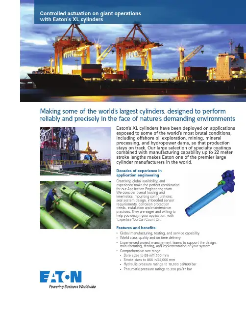
Controlled actuation on giant operations with Eaton's XL cylindersMaking some of the world’s largest cylinders, designed to perform reliably and precisely in the face of nature’s demanding environmentsDecades of experience in application engineeringCreativity, global availability, and experience make the perfect combination for our Application Engineering team. We consider overall loading and kinematics, mounting configurations, seal system design, imbedded sensor requirements, corrosion protection needs, installation and maintenance practices. They are eager and willing to help you design your application, with ‘Expertise Y ou Can Count On.’Eaton’s XL cylinders have been deployed on applications exposed to some of the world’s most brutal conditions, including offshore oil exploration, mining, mineral processing, and hydropower dams, so that production stays on track. Our large selection of specialty coatings combined with manufacturing capability up to 22 meter stroke lengths makes Eaton one of the premier largecylinder manufacturers in the world.Features and benefits•Global manufacturing, testing, and service capability •World class quality and on time delivery •Experienced project management teams to support the design, manufacturing, testing, and implementation of your system • Comprehensive size range• Bore sizes to 59 in/1,500 mm• Stroke sizes to 866 in/22,000 mm• Hydraulic pressure ratings to 10,000 psi/690 bar• Pneumatic pressure ratings to 250 psi/17 bar© 2016 Eaton All Rights Reserved Printed in USA Document No. E-CYCM-MS008-E1January 2016Eaton Hydraulics Group USA 14615 Lone Oak Road Eden Prairie, MN 55344USA Tel: 952-937-9800Fax: /hydraulicsEaton Hydraulics Group Europe Route de la Longeraie 71110 Morges Switzerland Tel: +41 (0) 21 811 4600Fax: +41 (0) 21 811 4601Eaton Hydraulics Group Asia Pacific Eaton Building 4th Floor, No.7 Lane280 Linhong Rd.Changning District Shanghai 200335China Tel: (+86 21) 5200 0099Fax: (+86 21) 2230 7240Complete and comprehensive rod coating portfolioEaton offers a comprehensive line of coatings ranging from nickel chromium to a laser cladded Eatonite ® coating, that provide the perfect balance of wear and corrosion resistance to meet your specific application needs. What’s more our Innovation Team pursues cutting edge R&D, advancing our work on next generation technologies.Civil engineeringFrom turbine governors and intake/radial/miter gates in hydropower dams, culvert valves in the Panama Canal, to movable bridges, Eaton has the product, global presence, application experience and resources to support existing and new installations.Oil and gas and marine To weather the harsh conditions of deepwater exploration for offshore drilling, Eaton’s Eatonite laser cladding was specifically designed to improve service life of piston rods for marine applications. Eaton also offers custom cylinder designs for heave compensation, riser tensioners, and mooring systems.Wave energy Eaton is constantly looking to develop pioneering technology to advance sustainable energy development. In addition to broad applications in hydropower dams and wind-power turbines, Eaton is designing solutions for tidal-power generation. Primary metals Whether it is the control of arc furnace electrodes, slag doors, gantry swivels/locks, ladle turrets, rolling mill tensioners, or chop gates, Eaton can provide robust and durable solutions with its comprehensive cylinder coating portfolio to excel in the rugged, demanding environmentof primary metals.High-end range ABC-L Eatonite laser cladding is a high performance, field repairable, 3rd party certified, cylinder rod coating for the most demanding applications and harshest operating environments, that provides uptime and reliability to enhance offshore rig/ship operating efficiency. Premier saltwater corrosion resistance.Mid range ABC-H Metallic HVOF sprayed coating for highly corrosive and abrasive environments.ABC-P3Metal oxide plasma sprayed coating for abrasion and corrosion resistance in fresh and brackish water environments and for Hypos applications.Standard range ABC-G2Galvanic nickel chromium plating with standard wear resistance and increased corrosion resistance.ABC-G1Galvanic hard chromium plating with standard wear resistance and corrosion resistance.。
设计编号SO3010 设计说明书设备名称:φ219×1500分汽缸图号: LY—FQG—219容器类别:Ⅰ类编制:校对:审核:批准:(使用单位)桂林莱茵生物制药设备制造有限公司年月日φ219×1500分气缸设计说明书一、分汽缸基本参数与性能最高工作压力 1.2Mpa最高工作温度194℃工作介质饱和水蒸汽工作方式连续式二、分汽缸的基本组成及用途分汽缸由圆筒体、标准椭圆形封头和支承式支座组成。
主要受压元件之间均采用对接全焊透焊缝连接,结构简单、合理。
筒体采用φ219×6的无缝钢管。
分汽缸主要用于使用前蒸汽分离。
三、分汽缸的设计依据及执行情况分汽缸的设计依据为:1、《压力容器安全技术监察规程》2、GB150-1998《钢制压力容器》按照上述“规程”和“标准”的要求,对分汽缸筒体进行了强度计算,结果表明,筒体的取用壁厚满足强度要求。
封头按JB/T4737-1995的标准选取。
设计选用的材料、结构形式、受压元件的焊接以及主要安全附件和仪表的选用都符合“规程”和“标准”的要求。
结果表明分汽缸设计合理,工艺性能和安全性能可靠。
四、分汽缸制造和验收标准分汽缸制造和验收必须执行下列标准:GB150-1998 《钢制压力容器》五、分汽缸安装使用说明分汽缸是蒸汽供汽系统中使用的分离容器。
分汽缸必须按照工艺的要求安装在锅炉供汽主管和各用汽管路的中间。
分汽缸上的进、出口分别安装相应的阀门,使锅炉输出的蒸汽进入分汽缸后分别送入用汽设备,在分汽缸中将输汽过程中的冷凝水分离出来。
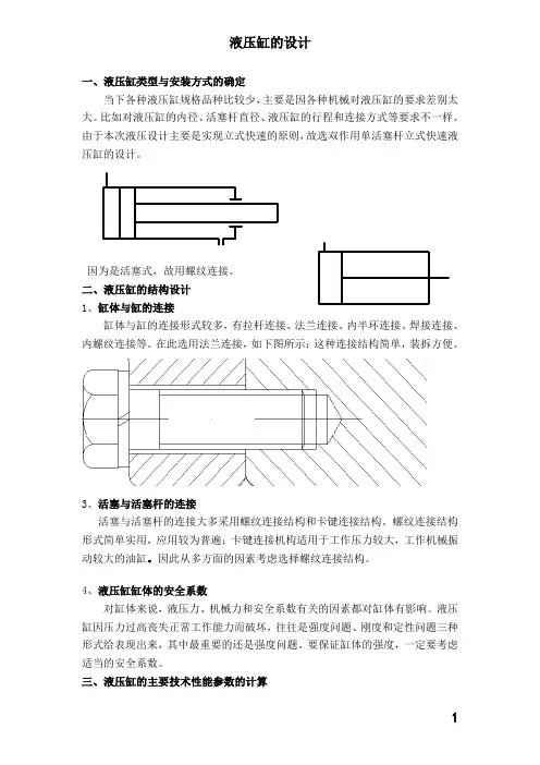
液压缸的设计一、液压缸类型与安装方式的确定当下各种液压缸规格品种比较少,主要是因各种机械对液压缸的要求差别太大。
比如对液压缸的内径、活塞杆直径、液压缸的行程和连接方式等要求不一样。
由于本次液压设计主要是实现立式快速的原则,故选双作用单活塞杆立式快速液压缸的设计。
因为是活塞式,故用螺纹连接。
二、液压缸的结构设计1、缸体与缸的连接缸体与缸的连接形式较多,有拉杆连接、法兰连接、内半环连接、焊接连接、内螺纹连接等。
在此选用法兰连接,如下图所示:这种连接结构简单,装拆方便。
3、活塞与活塞杆的连接活塞与活塞杆的连接大多采用螺纹连接结构和卡键连接结构。
螺纹连接结构形式简单实用,应用较为普遍;卡键连接机构适用于工作压力较大,工作机械振动较大的油缸。
因此从多方面的因素考虑选择螺纹连接结构。
4、液压缸缸体的安全系数对缸体来说,液压力、机械力和安全系数有关的因素都对缸体有影响。
液压缸因压力过高丧失正常工作能力而破坏,往往是强度问题、刚度和定性问题三种形式给表现出来,其中最重要的还是强度问题。
要保证缸体的强度,一定要考虑适当的安全系数。
三、液压缸的主要技术性能参数的计算(一)、压力所谓压力,是指作用在单位面积上的负载。
从液压原理可知,压力等于负载力与活塞的有效工作面积之比。
P=F/A(N/m2)式中:F—作用在活塞上的负载力(N)A—活塞的有效工作面积(m2)从上述可知,压力值的建立是因为负载力的存在而产生的,在同一个活塞的有效工作面积上,负载越大,所需的压力就越大,活塞产生的作用力就越大。
如果活塞的有效工作面积一定,压力越大,活塞产生的作用力就越大。
由此可知:1、根据负载力的大小,选择活塞面积合适的液压缸和压力适当的液压泵。
2、根据液压泵的压力和负载力,设计和选用合适的液压缸。
3、根据液压缸的压力和液压缸的活塞面积,确定负载的重量。
在液压系统中,为了便于液压元件和管路的设计选用,往往将压力分级。
见下表因本次液压缸的设计要求中已知的公称压力为30Mpa,由表1.1可知,本此液压缸属于高压。
目录1前言 (1)2 总体设计 (3)2.1总体方案论证 (3)2.1.1 加工对象工艺性的分析 (3)2.1.2 机床配置型式的选择 (3)2.1.3 定位基准的选择 (3)2.2确定切削用量及选择刀具 (4)2.2.1 选择切削用量 (4)2.2.2 计算切削力、切削扭矩及切削功率 (5)2.2.3 选择刀具结构 (5)2.3组合机床总体设计—“三图一卡” (6)2.3.1 被加工零件工序图 (6)2.3.2 加工示意图 (6)2.3.3 机床联系尺寸图 (7)2.3.4 机床生产率计算卡............................................................ 错误!未定义书签。
2.4夹具轮廓尺寸的确定........................................................... 错误!未定义书签。
3 组合机床左主轴箱设计.......................................................... 错误!未定义书签。
3.1绘制左主轴箱设计原始依据图........................................... 错误!未定义书签。
3.2主轴结构型式的选择及动力计算....................................... 错误!未定义书签。
3.2.1 主轴结构型式的选择........................................................ 错误!未定义书签。
3.2.2 主轴直径和齿轮模数的初步确定.................................... 错误!未定义书签。
3.2.3 主轴箱动力计算................................................................ 错误!未定义书签。
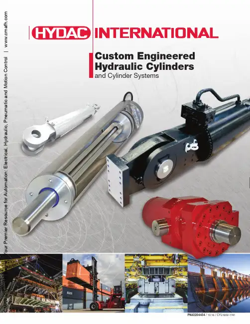
Custom Engineered Hydraulic Cylindersand Cylinder Systemsd y ne /H y d r a y n e - Y o u r P r e m i e r R e s o u r c ef o r A u t o m a t i o n : E l e c t r i c a l , H y d r a u l i c , P n e u m a t i c a n d M o t i o n C o n t r o l | w w w .c m a f h .c o mCYLINDER MANUFACTURING EXPERTISEHYDAC’s North America CYLINDER DIVISION, part of the global HYDAC Group, manufactures a broad range of custom engineered hydraulic cylinders and cylinder systems for mobile and industrial applications.Advanced manufacturing technology with capacity to handle:• Bore diameters up to 26 inches •Strokes up to 400 inches •Pressure up to 6000 psiCore competencies and strengths:• High speed machining with cutting-edge machine tool technology•M anufacturing processes utilize computer aided manufacture control to ensure precision, quality and efficiency •Structural Welding•W elding standards that meet ASME BPVC Sect IX and AWS D1.1 Structural Welding Codes•P roduct assembly with strict contamination control •S tatic and dynamic functional pressure testing •P LC controlled hydraulic testing equipment for pressures up to 10,000 PSI•P aint coating system that includes surface pretreatment and high temperature curing•S tandard paint is black primer and has excellent compatibility for customer finish requirements. In addition, special coatings and finishes can be applied to meet customer requirements to E l e c t r i c a l , H y d r a u l i c , P n e u m a t i c a n d M o t i o n C o n t r o l | w w w .c m a f h .c o m2-1741Road Construction MachineryHYDAC supplies cylinders for road construction machinery which meets the strictest standards for durability and functionalefficiency. The cylinders are tailored to make the best use of available space. These cylinders can be fitted with integrated valves, position sensors, pressure sensors, and an internal oil feed.Excavator CylindersExcavators and mining machines depend on the linear actuation of hydraulic cylinders to provide motion and functionality. In this demanding application, HYDAC cylinders are designed to be robust, reliable and easily serviceable to achieve a high level of performance that our customers expect.•C ustom-designed piston rod coatings, seal and guide sys-tems ensure a long service life.•Vibration-resistant design •Special sealing systems •Integrated valve technologyMobile Mining MachinesHydraulic cylinders for mobile machines used in surface mining and tunnelling are put under challenging contamination and temperature conditions. Our cylinders are designed to be extremely robust to withstand such conditions. Appropriate materials are used along with special piston rod coatings, wipers, seals and guide systems to ensure a long service life.CONSTRUCTION & MINING MACHINERYLeveling cylinder used on road constructionmachineryBreakaway cylinder for blast hole drillingHeavy-duty constructiongrade cylinderd r a y ne - Y o u r P r e m i e r R e s o u r c ef o r A u t o m a t : E l e c t r i c a l , H y d r a u l i c , P n e u m a t i c a n d M o t i o n C o n t r o l | w w w .c m a f h .c o mHYDAC manufactures hydraulic cylinders for mobile crane applications that allow for optimum crane design.Benefits and Special Features:•Minimal cylinder weight •Flexible cylinder sizing•Use of high strength materials•Position sensors, valves, and other components can be integrated into the cylinder•Anti-rotation piston rods are availableHYDAC designs boom and outrigger vehicle cylinders to be lightweight in order to meet permissible axle load requirements, and to meet strict leak tightness and functional requirements.Benefits and Special Features:• High strength materials are used to minimize weight •Customized seals prevent leakage•I ntegrated valves (load holding and counter balance)provide space and weight savings•S tructurally durable designs ensure long life •C orrosion resistant rod coatings assure durability BOOM & OUTRIGGER CYLINDER SYSTEMS10.16 / C Y L 1602-1741CYLINDERS FOR CRANESThree stage boom extend cylinder with integrated valvesOutrigger cylinder withintegrated HYDAC linear transducerLattice boom cylinder with integratedHYDAC directional control valved y ne /H y d r a y n e - Y o u r P E l e c t r i c a l , H y d r a u l i c , P n e u m a t i c a n d M o t i o n C o n t r o l | w w w .c m af h .c o m•Advance sealing technology •High strength materials •Integrated solutionsSTEERING & SUSPENSION CYLINDERSHYDAC cylinders provide steering and suspension functions in many mobile applications. Our cylinders are designed with robust sealing systems and coating technology to endure harsh environmental conditions. We also supply hydraulic cylinders equipped with gas accumulators developed specifically to take into account your requirements with respect to suspension characteristics, forces and installation space.Benefits and Special Features:•Internal or external accumulator integration •Low-friction design•Position and pressure sensor systems •Adjustable damping characteristics•R od coating tailored to suit operating conditions •Low temperature seals are availableSuspension cylinderwith integrated accumulatorSteering cylinder with integrated position sensorsINDUSTRIAL CYLINDERSo m a t i o n : E l e c t r i c a l , H y d r a u l i c , P n e u m a t i c a n d M o t i o n C o n t r o l | w w w .c m a f h .c o m10.16 / C Y L 1602-1741CYLINDER APPLICATION DATAQuote Due DateCONTACT INFORMATION____________________________________________________________________________________________________Company NameContact Name___________________________________________________________ ______________________________________________________Phone EmailIndicate One:DistributorEnd UserOEMOther_______________________________SPECIFICATIONSEAU: __________________Application: ___________________________________________________________________________Bore: __________________Stroke: _________________Rod Diameter: _______________ Fluid Type: ________________Maximum Allowable Working Pressure: __________ psiORMaximum Force Required: ___________psiTube Material Req.: ________________________________________ Rod Material Req.: _______________________________________Cushion: __________________________________________________ Port Type/Size: __________________________________________Electronic Feedback Req.: ___________________________________________Third Party Certification: _______________________Other Information: ____________________________________________________________________________________________________DUTYOperation:CompressionTensionBothCycle Rate: ______________Life Cycles: ________ORIENTATIONMounting Type:FlangeTrunnion Pin Eye Other__________Cylinder Orientation:VerticalHorizontalAngle _________°Known Side Load: _____________________________________________Degree of Misalignment (from Vertical): ____________°Other Information: ____________________________________________________________________________________________________ENVIRONMENTEnvironmental Temperature Range: ___________°F__________°FConstant? Yes NominmaxConditions: Corrosive Abrasive WaterOutdoorPaint Requirements: _______________________________________________Other Information: ____________________________________________________________________________________________________ADDITIONAL INFORMATION/REQUIREMENTSCustomer Drawing Available?YesNoOther Special Requirements: ___________________________________________________________________________________________To receive a quote, complete the Application Data Form and submit to your HYDAC Representatived y ne /H y d r a y n e - Y o u r P r e m i e r R e s o u r c ef o r A u t o m a t i o n : E l e c t r i c a l , H y d r a u l i c , P n e u m a t i c a n d M o t i o n C o n t r o l | w w w .c m a f h .c o mGlobal Headquarters HYDAC INTERNATIONALGMBH IndustriegebietD – 66280 Sulzbach/SaarGermanyTel.: +49 6897 509-01Fax: +49 6897 509-577Internet: Email:**************North America LocationsU SAHYDAC TECHNOLOGY CORPORATION Filter Division2260 City Line Road Bethlehem, PA 18017+1.610.266.0100HYDAC TECHNOLOGY CORPORATION Cooling System Division 1051 Airlie Parkway Denver, NC 28037+1.610.266.0100HYDAC TECHNOLOGY CORPORATION Accessory Division 2204 Avenue CBethlehem, PA 18017+1.610.266.0100HYDAC TECHNOLOGY CORPORATION Cooling System Division 445 Windy Point Drive Glendale Heights, IL 60139+1.630.545.0800HYDAC TECHNOLOGY CORPORATION Electronic Division Process Filter Division HYDAC CORPORATION Accumulator Division 90 Southland Drive Bethlehem, PA 18017+1.610.266.0100HYDAC TECHNOLOGY CORPORATION HYDAC CORPORATION Sales Office & Operations 1718 Fry Road, Suite 100 Houston, TX 77084+1.281.579.8100HYDAC TECHNOLOGY CORPORATION Filter System Division Process Filter Division 580 West Park Road Leetsdale, PA 15056+1.724.318.1100HYDAC TECHNOLOGY CORPORATION HYDAC CORPORATION NE Sales Office1660 Enterprise Parkway • Suite E Wooster, OH 44691+1.610.266.0100HYDAC TECHNOLOGY CORPORATION Hydraulic Division 450 Windy Point Drive Glendale Heights, IL 60139+1.630.545.0800HYDAC TECHNOLOGY CORPORATION HYDAC CORPORATION SE Sales Office 1051 Airlie Parkway Denver, NC 28037+1.610.266.0100HYDAC TECHNOLOGY CORPORATION Mobile Hydraulic Division1660 Enterprise Parkway • Suite E Wooster, OH 44691+1.610.266.0100HYDAC TECHNOLOGY CORPORATION HYDAC CORPORATION NW Sales Office1201 NE 144th St. Bldg. B, Suite 111 Vancouver, WA 98685+1.610.266.0100HYDAC CYLINDERS LLC 540 Carson Road North Birmingham, AL 35217+1.205.520.1220HYDAC TECHNOLOGY CORPORATION Hydraulic Division – Tech Center 430 Windy Point Drive Glendale Heights, IL 60139+1.630.545.0800C anadaHYDAC CORPORATION 14 Federal RoadWelland, Ontario, Canada L3B 3P2 +1.905.714.9322HYDAC CORPORATION Sales Office5160 75 Street NWEdmonton, Alberta, Canada T6E 6W2+1.780.484.4228HYDAC CORPORATION Sales OfficeMontreal, Québec, Canada J2M 1K9+1.877.539.3388M exic oHYDAC INTERNATIONAL SA de CV Calle Alfredo A Nobel No 35 Col Puente de Vigas Tlalnepantla, Edo Mexico CP 54090 Mexicod y ne /H y d r a y n e - Y o u r P r e m i e r R e s o u r c ef o r A u t o m a t i o n : E l e c t r i c a l , H y d r a u l i c , P n e u m a t i c a n d M o t i o n C o n t r o l | w w w .c m a f h .c o m。
第1章零件分析1.1零件作用缸体是发动机中最大的单独式部件,它基本上是一个金属体,其主要作用是润滑和冷却,为了达到这个目的,该部件被制造成既有汽缸又有油道和水道网。
1.2设计任务本次的设计任务是缸体的工艺设计,而根据课程设计任务要求,为了能准确的表达设计的理念和思想,且清楚顺利的完成本次缸体的工艺设计,特将设计任务分成一下四个部分:1.零件图1份2.毛坯图1份3.机械加工工艺过程综合卡片1份4.说明书1份一、零件图该零件的零件图见图1—1图1—1 零件图二、毛坯图由于缸体毛坯为铸件,毛坯最小加工余量为3mm~5mm,故选择加工余量为5mm。
根据主要加工表面的选择和定位基准的确定,在主要加工表面上增加加工余量,画出零件毛坯图。
该零件的毛坯图见图1—2图1—2 零件的毛坯图三、机械加工工艺过程综合卡片(见附录)1.3主要加工表面主要加工表面是根据零件图上的粗糙度要求确定的,粗糙度要求比较高的表面均需要加工,所以有以下5个主要加工表面;1.端面通过先粗铣后精铣的工序使其达到1.6的精度要求2.内圆经过粗镗、半粗镗、精镗的工序使其达到6.3的精度要求3.锥孔内表面通过先粗铣后精铣的工序使其达到3.2的精度要求4.底面通过粗铣直接使底面精度达到12.55.E面在镗床上加铣刀铣表面E使其达到12.5的精度要求1.4确定定位基准选择合理的加工工艺基准,直接关系到能否保证零件的加工质量。
一般来说,工艺基准可以分为粗基准和精基准。
1.4.1粗基准的选择粗基准的选择原则:a.对于同时具有加工表面和不加工表面的工件,为了保证不加工表面与加工表面之间的位置要求,应选择不加工表面为粗基准。
b.对于具有较多加工表面的工件,在选择粗基准时,应考虑合理的分配各表面的加工余量。
c.粗基准应避免重复使用。
在同一尺寸方向上,粗基准通常只允许使用一次,以免产生较大的定位误差。
对于上线的毛坯,其粗基准的选择尤为重要,如果粗基准选择不合理,会使加工余量分布不均匀,加工面偏移,造成废品。
气缸体设计说明书479Q汽油机气缸体总成设计摘要主要阐述了汽油机缸体各部分设计的要求、方法及其在479气缸体设计中的应用。
对缸体重要表面的尺寸、几何形状、相互位置提出了严格的公差要求。
在结构设计中经过采用龙门式缸体结构、合金铸铁材料以及结构细节的设计来保证其有足够的强度和刚度,特别是有足够的刚度。
还特别注减轻其质量,改进铸造和加工工艺性,以求尽量降低成本。
关键词:汽油机,缸体,设计The Design of 479Q Gasoline Engine Block AssemblyAbstractThis thesis is concerned with the request and approach of each part of the engine cylinder block in design as well as the use of the 479QA cylinder block‘s design. It presents strict tolerance in the principal surface size, geometry and mutual position. When designing, it has sufficient intensity and rigidity, especially the latter. It satisfies the need by adopting these means -the material of the cast -iron of alloy, detailed design of structure etc. The thesis focuses on reducing the cost by means of reducing the quantity, improving foundry and processing.Key words: gasoline engine, cylinder block;,design目录摘要 ....................................................................................... 错误!未定义书签。
492QD三气门汽油机设计(气缸盖)摘要气缸盖是汽油机最复杂,同时也是最重要的零件之一。
气缸盖与活塞、气缸构成燃烧室空间。
在气缸盖内一般有进、排气道,冷却水腔、润滑油孔道,并装有配气机构和火花塞等零部件。
气缸盖设计的好坏,直接影响着汽油机的动力性,经济性和可靠性。
本次设计是基于原有的492Q汽油机的基础上进行改进设计,关键问题是将两气门改成三气门,采用两个进气门一个排气门,进排气门的气门面积都有所增大,这样可以增加气体流通面积,减小流动阻力,提高充气效率,提高了动力性和经济性。
汽油机采用中置凸轮轴,因此缸盖上有贯穿的推杆孔,另外还有贯穿的螺栓孔,这些在布置气道的时候都应该考虑。
对于进气道而言,不仅关系到气缸的充气效率,而且还与混合气的形成及燃烧过程的气流组织等密切相关。
对于排气道,应尽可能的减小流动阻力,使排气流畅的排出。
同时,在设计三气门的时候,可以将火花塞中心布置,改进了燃烧过程,提高了经济性和排放性。
关键词:汽油机,气缸盖,三气门,改进THE IMPRONEMENT OF THE DESIGN OF 492QD GASOLINE ENGIN E’S CYLINDER HEADABSTRACTThe cylinder head of an engine ,is the most complex shape structure and one of the most important components. The cylinder head, piston,and the cylinder compose the combustion chamber together. There are intake and exhaust manifold, water jacket, the road of the oil, air introduction structure and spark etc in the cylinder head. The quality of the cylinder head’s design will affect the power performance, fuel economy and reliability directly.This design is carried out on the base of the prior 492 gasoline engine, and the key of this design lie in changing the valves from two to three, that is two intake valves and one exhaust. Both the in and out air flow area were enlarged, which decrease the flow resistance and improve the air inflation efficiency meanwhile, thus improved its power and fuel economy. The improved cylinder head remain the same structure as the prior 2 valves engine ,which control the valves through camshaft mounted in the crankcase and tappets, so the holes of the push rod and bolt still should be arranged in the cylinder head. The arrangement of the intake manifold not only affect the intake efficiency ,but also has something to do with the form of the mixture, the combustion process and the organization of the air flow. As to the exhaust manifold, just decrease the flow resistance without considering the turbulence. In addition the spark could be mounted in the cylinder center vertically, so that the spark could be distributed more equality. Which can improve the quality of the mixture and the combustion, and raised the performance of the fuel consumption and emission.KEY WORDS: gasoline engine,cylinder head,three valves,improvement目录前言 (1)第一章汽油机技术的发展 (2)§1.1 汽油机技术概况及发展趋势 (2)§1.1.1 概述 (2)§1.1.2 汽油机技术的发展趋势 (2)§1.2 我国汽油机技术的发展 (6)第二章 492Q汽油机的整体设计 (10)§2.1 设计要求和技术指标 (10)§2.2 内燃机主要尺寸的确定 (10)§2.2.1 曲柄半径的确定 (10)§2.2.2 计算排量 (10)§2.2.3 计算活塞平均速度 (10)§2.2.4 计算平均有效压力 (11)§2.2.5 计算气缸中心距 (11)第三章 492Q三气门汽油机气缸盖设计 (12)§3.1 气缸盖设计基本要求 (12)§3.1.1 概述 (12)§3.2 气缸盖结构设计 (13)§3.2.1 气缸盖结构形式选择 (13)§3.3 气缸盖材料的选择 (19)第四章形位公差的确定 (21)§4.1汽油机铸铁气缸盖技术条件 (21)§4.2 492Q的技术条件 (22)§4.2.1公差带 (22)§4.2.2 形状和位置公差 (22)§4.2.3 粗糙度 (22)§4.3尺寸公差、形状公差及粗糙度的分析 (23)§4.3.1 尺寸公差的分析 (23)第五章结论 (25)参考文献 (26)致谢 (27)前言当代世界,环境污染和能源危机越来越严重,如何节约资源,保护环境越来越受到人们的重视,因此各个国家相继推出了自己的排放法规。
PROE设计综合训练<气缸设计说明书>院系:材料科学与工程学院专业班级:材型 1101姓名:温雪学号: 20111402129指导老师:刘彬彬一、设计思路(1)金属垫片(2)弹簧垫片(3)螺母(4)螺柱(5)气缸盖(6)气缸壳二、设计步骤零件一 金属垫片步骤1建立新文件(1)单击菜单[文件]→[新建]命令,选择“新建”类型,在名称栏中输入新建文件名称:“jinshudianpian ”在菜单工具栏中单击“新建”按钮,在弹出的“新建”对话框中选择“零件”单选按钮。
输入文件名“jinshudianpian ”,去掉“使用缺省模板”的对勾,单击,在弹出的新建文件夹选项对话框中选择公制模板mmns_part_solid。
(2)单击确定按扭,进入零件设计工作环境。
步骤2 拉伸(1)单击拉伸按钮,在“拉伸”界面上选择“实体”,以指定生成的拉伸实体,单击放置按钮,打开上滑板面板。
单击上滑面板中的定义按钮,系统弹出草绘对话框并提示用户选择草绘平面,选择FRONT基准面作为草绘平面,接受系统默认的参照方向,单击“草绘”按钮,进入草绘。
(2)单击“圆形”按钮,绘制两个同心圆,并分别修改尺寸为420.00和240.00,如图1-1,。
修改完成后单击草绘器工具栏中的按钮退出草绘模式。
(3)在拉伸界面的“深度”对话框设置拉伸深高度为2.00,单击界面按钮或鼠标中键完成拉伸特征的创建,如图1-2。
图1-1 图1-2步骤3 阵列/拉伸(1)单击拉伸按钮,在“拉伸”界面上选择“实体”,以指定生成的拉伸实体,单击放置按钮,打开上滑板面板。
单击上滑面板中的定义按钮,系统弹出草绘对话框并提示用户选择草绘平面,选择FRONT基准面作为草绘平面,接受系统默认的参照方向,单击“草绘”按钮,进入草绘。
(2)单击“圆形”按钮,绘制一个圆,修改尺寸为30,如图1-3,。
修改完成后单击草绘器工具栏中的按钮退出草绘模式。
(3)在拉伸界面的“深度”对话框设置拉伸深高度为148.49,单击界面按钮或鼠标中键完成拉伸特征的创建。
目录设计题目---------------------------------------------------------------------------2液压缸的选型---------------------------------------------------------------------2液压缸主要参数的计算液压缸主要性能参数-----------------------------------------------------2缸筒内径(缸径)计算--------------------------------------------------2缸壁壁厚的计算------------------------------------------------------------2流量的计算------------------------------------------------------------------3底部厚度计算---------------------------------------------------------------4最小导向长度的确定------------------------------------------------------4主要零部件设计与校核缸筒的设计------------------------------------------------------------------5缸筒端盖螺纹连接的强度计算-----------------------------------------6 缸筒和缸体焊缝连接强度的计算--------------------------------------6 活塞设计----------------------------------------------------------------------7 活塞的密封-------------------------------------------------------------------8活塞杆杆体的选择----------------------------------------------------------8活塞杆强度的校核----------------------------------------------------------8液压缸稳定性校核----------------------------------------------------------9活塞杆的导向、密封和防尘---------------------------------------------9 致谢-----------------------------------------------------------------------------10参考文献-------------------------一.设计题目双作用单杆活塞式液压缸设计主要设计参数:系统额定工作压力:p=25(Mpa)驱动的外负载:F=50(KN)液压缸的速度比:λ=1.33 液压缸最大行程:L=640(mm)液压缸最大伸出速度:λ=4(m/min) 液压缸最大退回速度:v t=5.32(m/min)缸盖连接方式:螺纹连接液压缸安装方式:底座安装缓冲型式:杆头缓冲二.液压缸的选型液压缸是液压装置中将液压能转换为机械能,实现直线往复运动或摆动往复运动的执行元件。
480柴油机气缸盖设计毕业设计说明书第一章前言内燃机以其热效率高、结构紧凑,机动性强,运行维护简便的优点著称于世界。
柴油机的发展已有一百多年的历史,通过这一长时期的不断改进和提高,已经发展到了比较完善的程度。
目前世界上内燃机的拥有量大大超过了任何其它的热力发动机,在国民经济中占有相当重要的地位。
现代内燃机更是成为了当今用量最大、用途最广、无一与之匹敌的最重要的热能机械。
而柴油机是目前产业化应用的各种动力机械中热效率最高、能量利用率最好、最节能的机型,它已经成为汽车、农业机械、工程机械、船舶、内燃机车、地质和石油钻机、军用、通用设备、移动和备用电站等装备的主要配套动力。
小型柴油机比汽油机节油15%~30%,二氧化碳各种废气的排放也比汽油机的要低。
其应用范围越来越广。
随着强化程度的提高,柴油机单位功率的重量也显著降低。
为了节能,各国都在注重改善燃烧过程,研究燃用低质燃油和非石油制品燃料。
此外,降低摩擦损失、广泛采用废气涡轮增压并提高进气量、进一步轻量化、高速化、低油耗、低噪声和低污染,都是柴油机的重要发展方向。
随着柴油机技术的发展,加上柴油汽车在动力性、经济性和大修期等方面比汽油车占优势,汽车柴油化的趋势越来越明显。
交通部门专家预测:由于清洁燃料汽车(电动车、太阳能车、燃氢汽车等)近期难以实现技术上的突破,还无法达到实用普及,21世纪将是柴油机大行其道的时代。
§1.1柴油机技术概述及发展趋势§1.1.1概述1882年德国人狄赛尔(RudolfDiesel)提出了柴油机工作原理,1896年制成了第一台四冲程柴油机。
一百多年来,柴油机技术得以全面的发展,应用领域越来越广泛。
大量研究成果表明,柴油机是目前被产业化应用的各种动力机械中热效率最高、能量利用率最好、最节能的机型。
装备了最先进技术的柴油机,升功率可达到30~50kW/l,扭矩储备系数可达到0.35以上,最低燃油耗可达到198g/kW·h,标定功率油耗可达到204g/kW·h;出于对能源和环保因素的考虑,汽车柴油化已经成为一种国际潮流。
目录第一章绪论 (2)1.1 课题研究的意义及现状 (2)1.1.1 发动机 (2)1.1.2 发动机气缸盖 (3)1.1.3汽车制造技术与CAD技术 (4)1.2 专业课程设计任务说明 (5)1.2.1 设计内容 (5)1.2.2 设计要求 (5)第二章发动机缸盖设计分析加工 (6)2.1 气缸盖设计分析 (6)2.1.1 功用分析 (6)2.1.2 结构分析 (6)2.1.3 材料分析 (7)2.1.4 技术分析 (8)2.2 气缸盖设计要求 (8)2.3缸盖图纸设计 (9)2.3.1 功能结构读图 (10)2.3.2 尺寸定位及标注 (12)2.3.3手绘图纸概述 (13)2.4机械加工工艺技术关键分析 (13)2.4.1 定位方式 (14)2.4.2 气门座底孔与导管孔底孔的加工 (14)2.4.3气门座圈锥面加工方式 (14)2.4.4导管孔的加工方式 (14)2.5加工设备及工艺装备的选择 (15)第三章后记 (17)参考文献 (18)致谢.................................................................................................................................. 错误!未定义书签。
第一章绪论1.1 课题研究的意义及现状1.1.1 发动机发动机是一种能够把其它形式的能转化为另一种能的机器,通常是把化学能转化为机械能。
发动机既适用于动力发生装置,也可指包括动力装置的整个机器(如:汽油发动机、航空发动机)。
发动机最早诞生在英国,所以,发动机的概念也源于英语,它的本义是指那种“产生动力的机械装置”。
有人把引擎称为发动机,其实,发动机是一整套动力输出设备,包括变速齿轮、引擎和传动轴等等,可见引擎只是整个发动机的一个部分,但却是整个发动机的核心部分。
人们不断地研制出各种不同类型的发动机,但不管哪种发动机,它的基本前提都是要以某种燃料燃烧来产生动力。
1、引言气缸是一种传动装置,它将压缩空气的压力能转化成为机械能,根据现场情况,确定气缸形式为双作用活塞气缸,安装方式为底座固定式。
气缸由许多零件所组成,包括活塞、活塞杆、缸体密封装置、前后端盖、联接螺栓及进排气管接头等。
下面根据定位气缸工作条件,逐一对各零件进行设计。
2、 气缸主要尺寸以及相关的技术要求2.1缸体和活塞杆1)缸体内径和活塞杆直径: 气缸工作载荷 1400F N = 理论输出力 0140020000.7F F N η=== 根据《机械设计手册》作用力的公式()2204F D d p π=-,d 取(0.3~0.4)D ,令0.4d D =即()2200.164F DD pπ=-77.8D mm====≈查《机械设计手册》取缸体内径80D mm =,查表 4.3.3活塞杆的直径32d mm =。
根据工作位置和设计图纸计算理论行程为60mm ,但在实际中防止活塞对两端端盖的冲击,不能使用满行程。
查《机械设计手册》行程取55mm ,确定活塞杆总长480mm 。
取缸体内径D=80mm 活塞杆直径d=32mm可设:1292l mm = ,132d mm =,28l mm =,245d mm =,338l mm =,335d mm = 416l mm =,433d mm =,5126l mm =,530d mm =。
2) 缸体和活塞杆的技术要求: 缸体:(1) 由于缸体是气压缸的主体件,它要承受很大的气压力,它一旦损坏,气压缸基本上就报废了。
采用一次铸造成型,不允许有夹渣气孔等铸造缺陷,并且选用HT200。
缸体内壁的表面粗糙度要求较高,以便活塞及其密封件、支承件能在其中滑移和保证密封效果,减少磨损。
(2) 内径D采用H7或H8级配合,Ra值要求达到0.8um(3) 热处理:调质,硬度在241—285HB(4) 缸体内径的圆度,锥度,圆柱度公差不大于内径公差(5) 缸体的直线度公差在500mm长度上不大于0.03mm,内孔轴线与端面的垂直度误差不大于0.03mm(6) 缸体端面对内径的垂直度公差在直径100mm上不大于0.04mm,内孔对两端支承外圆的同轴度误差不大于0.025m(7) 内孔圆柱度误差不大于0.04mm,内孔轴线的直线度误差不大于0.1/1000mm(8) 内孔必须光洁无刻痕,不允许有毛刺以免划伤密封件(9)组织应紧密,不得有砂眼,针孔及疏松,必要时要用泵验漏(10)为了防腐蚀,提高寿命,缸体内径可以镀铬,镀层厚度一般为0.03-0.05mm,进行研磨或抛光,缸体外露表面可涂耐油油漆(11) 通往油口、排气孔的内孔口必须倒角,内孔倒角缸体壁厚的确定:缸体的壁厚为:&≥PyD/2〔a〕式中&为气压缸壁厚(m)D=0.08气压缸的内径(m)Py=0.625 MPa试验压力,一般取最大工作压力的(1.25-1.5)倍(MPa)〔a〕缸体材料的许用应力。
479Q汽油机气缸体总成设计摘要主要阐述了汽油机缸体各部分设计的要求、方法及其在479气缸体设计中的应用。
对缸体重要表面的尺寸、几何形状、相互位置提出了严格的公差要求。
在结构设计中通过采用龙门式缸体结构、合金铸铁材料以及结构细节的设计来保证其有足够的强度和刚度,尤其是有足够的刚度。
还特别注减轻其质量,改善铸造和加工工艺性,以求尽量降低成本。
关键词:汽油机,缸体,设计The Design of 479Q Gasoline Engine Block AssemblyAbstractThis thesis is concerned with the request and approach of each part of the engine cylinder block in design as well as the use of the 479QA cylinder bloc k‘s design. It presents strict tolerance in the principal surface size, geometry and mutual position. When designing, it has sufficient intensity and rigidity, especially the latter. It satisfies the need by adopting these means -the material of the cast -iron of alloy, detailed design of structure etc. The thesis focuses on reducing the cost by means of reducing the quantity, improving foundry and processing.Key words: gasoline engine, cylinder block;,design目录摘要 (1)Abstract (2)第一章概述 (5)1.1气缸分类 (5)1.2气缸体冷却方式 (6)1.3气缸数量 (6)第二章缸体的工作情况和设计要求 (8)2.1 缸体的工作情况 (8)2.2 缸体的设计要求 (8)第三章气缸体方案确定 (10)3.1 缸体的结构型式的选择 (10)3.2 缸体结构细节的设计 (10)3.3机体的支承形式 (11)3.4 气缸的排列方式 (12)3.5 曲轴箱的设计 (13)3.6 机体冷却水套 (13)3.7 机体润滑油道 (14)3.8 机体材料 (18)3.9降噪处理方面 (19)第四章缸体基本尺寸的确定 (20)第五章气缸结构设计 (21)第六章缸体的结构工艺性 (23)6.1 铸造工艺性 (23)6.2 机械加工方便性 (23)第七章提高缸体可靠性的措施 (26)7.1为了提高气缸套的耐磨性,可以从以下几方面选择改进措施: (26)7.2 提高缸体铸件精度 (26)7.21 基准选择 (26)7.22 水套芯做工艺基准 (27)7.23 正确选择收缩率 (27)7.3 气缸体铸件气孔缺陷的防止措施 (27)7.31 气孔的产生分析 (27)7.32 气孔缺陷的防止措施 (27)7.33 浇注系统的设计 (28)7.34 降低造型材料的发气量,提高发气速度 (28)参考文献 (31)总结与展望 (33)致谢 (34)附录:翻译 (35)第一章概述气缸体是发动机的主体,它将各个气缸和曲轴箱连成一体,是安装活塞、曲轴以及其他零件和附件的支承骨架。
汽缸体一般用灰铸铁铸成,汽缸体上部的圆柱形空腔称为气缸,下半部为支撑曲轴的曲轴箱,气内腔为衢州运动的空间,在汽缸体内部铸有许多加强肋,冷却水套和润滑油道等。
气缸体应具有足够的强度和刚度,根据气缸体与油底壳安装平面的位置不同,通常把气缸体分为以下三种形式:一般是气缸体,龙门式气缸体,隧道式气缸体。
气缸体的工作条件十分恶劣。
它要承受燃烧过程中压力和温度的急剧变化以及活塞运动的强烈摩擦。
因此,它应具有以下性能:①有足够的强度和刚度,变形小,保证各运动零件位置正确,运转正常,振动噪声小。
②有良好的冷却性能,在缸筒的四周有冷却水套,以便让冷却水带走热量。
③耐磨,以保证气缸体有足够的使用寿命。
气缸体上部是并列的气缸筒,目前多镶有气缸套。
气缸体的下部是曲轴箱,用来安装曲轴,其外部还可安装发电机、发动机支架等各种附件。
气缸体大多用铸铁或铝合金铸造而成,铝合金缸体成本较高,但重量轻、冷却性能好,得到越来越广泛的应用。
机体是构成发动机的骨架,是发动机各机构和各系统的安装基础,其内、外安装着发动机的所有主要零件和附件,承受各种载荷。
因此,机体必须要有足够的强度和刚度。
机体组主要由气缸体、曲轴箱、气缸盖和气缸垫等零件组成。
1.1气缸分类水冷发动机的气缸体和上曲轴箱常铸成一体,称为气缸体——曲轴箱,也可称为气缸体。
气缸体一般用灰铸铁铸成,气缸体上部的圆柱形空腔称为气缸,下半部为支承曲轴的曲轴箱,其内腔为曲轴运动的空间。
在气缸体内部铸有许多加强筋,冷却水套和润滑油道等。
气缸体应具有足够的强度和刚度,根据气缸体与油底壳安装平面的位置不同,通常把气缸体分为以下三种形式。
(1)一般式气缸体其特点是油底壳安装平面和曲轴旋转中心在同一高度。
这种气缸体的优点是机体高度小,重量轻,结构紧凑,便于加工,曲轴拆装方便;但其缺点是刚度和强度较差(2)龙门式气缸体其特点是油底壳安装平面低于曲轴的旋转中心。
它的优点是强度和刚度都好,能承受较大的机械负荷;但其缺点是工艺性较差,结构笨重,加工较困难。
(3)隧道式气缸体这种形式的气缸体曲轴的主轴承孔为整体式,采用滚动轴承,主轴承孔较大,曲轴从气缸体后部装入。
其优点是结构紧凑、刚度和强度好,但其缺点是加工精度要求高,工艺性较差,曲轴拆装不方便。
为了能够使气缸内表面在高温下正常工作,必须对气缸和气缸盖进行适当地冷却。
冷却方法有两种,一种是水冷,另一种是风冷。
水冷发动机的气缸周围和气缸盖中都加工有冷却水套,并且气缸体和气缸盖冷却水套相通,冷却水在水套内不断循环,带走部分热量,对气缸和气缸盖起冷却作用。
现代汽车上基本都采用水冷多缸发动机,对于多缸发动机,气缸的排列形式决定了发动机外型尺寸和结构特点,对发动机机体的刚度和强度也有影响,并关系到汽车的总体布置。
按照气缸的排列方式不同,气缸体还可以分成单列式,V型和对置式三种。
(1)直列式发动机的各个气缸排成一列,一般是垂直布置的。
单列式气缸体结构简单,加工容易,但发动机长度和高度较大。
一般六缸以下发动机多采用单列式。
例如捷达轿车、富康轿车、红旗轿车所使用的发动机均采用这种直列式气缸体。
有的汽车为了降低发动机的高度,把发动机倾斜一个角度。
(2)V型气缸排成两列,左右两列气缸中心线的夹角γ<180°,称为V型发动机,V型发动机与直列发动机相比,缩短了机体长度和高度,增加了气缸体的刚度,减轻了发动机的重量,但加大了发动机的宽度,且形状较复杂,加工困难,一般用于8缸以上的发动机,6缸发动机也有采用这种形式的气缸体。
(3)对置式气缸排成两列,左右两列气缸在同一水平面上,即左右两列气缸中心线的夹角γ=180°,称为对置式。
它的特点是高度小,总体布置方便,有利于风冷。
这种气缸应用较少。
气缸直接镗在气缸体上叫做整体式气缸,整体式气缸强度和刚度都好,能承受较大的载荷,这种气缸对材料要求高,成本高。
如果将气缸制造成单独的圆筒形零件(即气缸套),然后再装到气缸体内。
这样,气缸套采用耐磨的优质材料制成,气缸体可用价格较低的一般材料制造,从而降低了制造成本。
同时,气缸套可以从气缸体中取出,因而便于修理和更换,并可大大延长气缸体的使用寿命。
气缸套有干式气缸套和湿式气缸套两种。
干式气缸套的特点是气缸套装入气缸体后,其外壁不直接与冷却水接触,而和气缸体的壁面直接接触,壁厚较薄,一般为1~3mm。
它具有整体式气缸体的优点,强度和刚度都较好,但加工比较复杂,内、外表面都需要进行精加工,拆装不方便,散热不良。
1.2气缸体冷却方式湿式气缸套的特点是气缸套装入气缸体后,其外壁直接与冷却水接触,气缸套仅在上、下各有一圆环地带和气缸体接触,壁厚一般为5~9mm。
它散热良好,冷却均匀,加工容易,通常只需要精加工内表面,而与水接触的外表面不需要加工,拆装方便,但缺点是强度、刚度都不如干式气缸套好,而且容易产生漏水现象。
应该采取一些防漏措施。
为了能够使气缸内表面在高温下正常工作,必须对气缸和气缸盖进行适当地冷却。
冷却方法有两种,一种是水冷,另一种是风冷。
水冷发动机的气缸周围和气缸盖中都加工有冷却水套,并且气缸体和气缸盖冷却水套相通,冷却水在水套内不断循环,带走部分热量,对气缸和气缸盖起冷却作用。
1.3气缸数量气缸数:汽车发动机常用缸数有3、4、5、6、8、10、12缸。
排量1升以下的发动机常用三缸,1~2.5升一般为四缸发动机,3升左右的发动机一般为6缸,4升左右为8缸,5.5升以上用12缸发动机。
一般来说,在同等缸径下,缸数越多,排量越大,功率越高;在同等排量下,缸数越多,缸径越小,转速可以提高,从而获得较大的提升功率。
1.4课题研究意义从经济学角度出发,汽车工业作为支柱产业,自从1885年德国工程师卡尔.奔驰设计制造了第一辆单缸四冲程内燃机汽车以来,世界汽车工业从当初年产量不足千台到如今汽车工业已经年产量超过5000万辆的现代大工业。
在各个汽车大国中,汽车产业在其国民经济中有着很快的生产发展;它带有很强的连锁效应,诱导了许多新产业的崛起;同时它对其所处地区的经济结构和发展变化有着深刻而广泛的影响。
从环境的角度讲,作为节能减排的主要手段之一,汽车的轻量化已成为各大汽车厂商所追求的目标。
从发动机角度来讲机体是发动机中单件质量最大的零件,一般都超过发动机质量的1/4,甚至接近1/3。
如此一来,世界范围内,针对汽车发动机直至发动机机体等的很多轻量化研究和技术正在不断地被研究和改进。
2009年,我国的汽车销量以1350万的成绩,超过美国、日本和欧洲大陆,名列榜首。
但是这些销量中的绝大多数品牌为与我国企业合作的跨国公司。
造成这一局面的主要原因是我国缺少对汽车核心技术的掌握。
所以目前汽车的核心技术和自主研发是我国汽车业所要努力的方向,对我国汽车业有着至关重要的意义。
我国轿车用汽油发动机是伴随着轿车的引进而引进。
目前我国轿车汽油发动机主要有三种生产方式:一种是整车生产企业自己生产发动机:如上海大众、东风本田上海通用;第二种是由专业汽油发动机厂生产供应汽车整车企业。
如沈阳航天三菱汽车发动机制造有限公司生产4G63、4G64发动机供给中华2.0L、2.4L、东方之子等车。