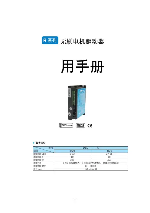
MMT 无刷控制器使用说明书
- 格式:pdf
- 大小:789.42 KB
- 文档页数:15
航模无刷电子调速器说明书感谢您使用本产品!本产品功率强大,错误的使用可能导致人身伤害和设备损坏,强烈建议您在使用设备前仔细阅读本说明书并保存,严格遵守规定的操作程序。
我们不承担因使用本产品或擅自对产品进行改造所引起的任何责任,包括但不限于对附带损失或间接损失的赔偿责任。
我们有权在不经通知的情况下变更产品的设计、外观、性能及使用要求。
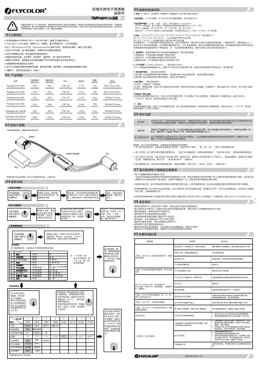
03 连线示意图*每种规格的产品外观有差异,图片为代表型号仅供参考,以实物为准1. 刹车: [1] 无刹车 [2]软刹车 [3]重刹车 [4]很重刹车 (出厂默认值为无刹车)2.电池类型: [1]LiPo(锂电) [2] NiCb/NiMh(镍氢/镍隔) (默认值为Li Po )3.低压保护阈值:[1] 低 [2]中 [3]高 ;默认值为中(3.0V/65%)对于Ni-xx电池组:低/中/高中止电压是电池组初始电压值的50% / 65% / 75% 对于Li-xx电池组:低(2.8V/节)/ 中(3.0V/节)/ 高(3.2V/节)。
例如:对于一个14.8V/4节的Li-po电池组来说,低压保护电压为 11.2V低 / 12.0V中 / 12.8V为高。
4.进角:[1]0° [2]3.75° [3]7.5° [4]11.25° [5]15° [6]18.75° [7]22.5°[8]26.25° (默认值为15°)低(0°/ 3.75°/ 11.25°/15°/ 18.75°)--为大多数的內转子马达设置高(22.5°/ 26.25°)--为6极和6极以上的外转子的马达设置大多数情况下,15°进角适用于所有类型的马达,但为了提高效率,我们建议对2极马达使用低进角设置(一般的内转子),6极和6极以上(一般的外转子)马达使用高进角。
__________________________________________________________________________________感谢您购买了EASYCO无刷电机电子调速器。
这款产品是专为遥控航模所设计的。
因为大功率输出的遥控模型的危险性,我们强力建议您在使用这款产品前一定仔细的阅读产品说明。
安全建议!1.所有的EASYCO遥控模型产品仅适于成年人使用。
2.在您连接电池线之前,确保其它的连接线正确连接。
3.EASYCO TECHNOLOGY不承担任何由使用本产品而引起的直接或间接的损害、伤害的赔偿责任。
4.当模型和动力系统相连时必须和操控者及其它人保持足够的安全距离。
5.在远离人群的地方飞行。
6.了解当地对于遥控模型飞行的相关法律条例。
产品特点:1.进角自动调整,无需设置。
2.极其轻微的启动过程。
最低到3%的动力输出就可以平滑启动。
平滑启动并保持足够的扭矩。
3.最好的油门曲线和最大的油门行程范围。
4.周全细致的保护功能:包括低电压保护\过热保护\油门信号丢失保护\安全上电保护\缺相保护\堵转保护。
●启动快慢完全由油门控制。
在运转过程中只有堵转、缺相才会立即保护停机。
停机后,油门需回位才可重起。
●较好的低电压保护模式。
逐步降低动力输出以尽量维持电压在保护设定值之上。
当降到30%功率时,将停机。
●当温度超过保护值时,降低功率,降低速率由温升速率决定。
●信号丢失在3秒内降到20%功率后停机。
●安全上电保护。
接通电源时无乱遥控杆在何位置皆可保证电机不会启动,确保安全。
5.较为简单的参数设定。
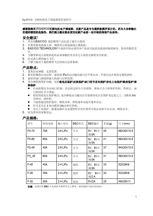
产品规格:型号持续电流输入电压BEC形式BEC输出重量(g)尺寸(mm)4568X30X10.5 FS-7070A2-6LiPo开关5V、6V可调/3AFS-6060A2-6LiPo开关5V、6V可4168X30X10.5调/3A3764X30X10.5 FS-4545A2-6LiPo开关5V、6V可调/3AFS_3560A2-6LiPo开关5V、6V可3159X30X10.5调/3A3352X29X9 F-4545A2-4LiPo线性5V、6V可调/3AF-3535A2-4LiPo线性5V、6V可3252X29X9调/2AF-3030A2-4LiPo线性5V/2A2548X25X11注意:电调自带BEC不支持四节和四节以上锂电(或其他相当电压的电池)__________________________________________________________________________________参数设置说明:1.油门行程设定:适应市场所有遥控器。

MMT-24RT 10BL 直流驱动器使用说明济南科亚电子科技有限公司规格及型号:最大最大直流电压输出电流输出电压工作范围型号DC : (A) DC:(V) DC:(V)DC12/20BL-4Q02 20 10.8 10-15DC24/20BL-4Q02 20 22.8 20-55DC36/20BL-4Q02 20 34.6 20-55DC48/20BL-4Q02 20 46.5 20-55一、产品特点:该系列调速器为低压直流四象限再生脉宽调速,采用专用单片机智能控制,响应速度快、运转平稳、工作可靠、保护功能齐全等。
◆采用SMT技术、体积小◆脉宽调制电机运转噪音小、高效率、低维护、更好的提高直流电机的使用寿命。
◆四象限再生运转模式◆再生制动功能不需要外部换向接触器,不会导致电机零部件或其组件过热或者烧毁◆使能/换向端子通过简单的无源开关量或晶体管集电极开路来实现其中某一项功能即可。
◆状态指示灯电源指示和过流报警指示能提供调速器的可视化状态。
◆输出电流设定功能(限幅)◆转矩补偿功能◆双闭环PI调节(电流、电压)◆标准模拟量信号控制模拟量:0-5V 0-10V或电位器控制均可◆较宽的输入电压范围:10-55V二.性能指标1、PWM脉宽调制2 、调速比:1:1003 、控制电位器:(1K……50K )/2W4、输入电压:20-55V VDC5、输出电流:0-20A (限幅)6、输入阻抗:≥50KΩ7、转速(基准精度%): 1 %8、启动/制动时间:1-20 S9、环境温度:-10℃~+50℃10、环境湿度:≤80RH(无结露)(相对湿度)11、绝缘耐压:1100V DC 1分钟12、绝缘电阻:>20 MΩ13、漏电流:≤ 0.9 mA14 重量:0.25Kg15、适用于稀土、永磁和他励马达三、外形尺寸:见图112*76*33mm四、安装要求:警告1、不能带电安装、接线或移除控制器。
否则可能造成事故或严重的伤害。
1. 标题XC500TF,XC550TF,XC550TF-MJ无刷速度控制器,,货号等。
使用说明书使用产品前,请仔细阅读本使用说明书,并妥善保管。
2. 介绍如今,无刷浪潮正迅速地席卷整个遥控车领域。
在比较高级别的比赛中,几乎已经看不到有刷马达的身影。
在成功推出业界领先水平的XC800TF竞赛级ESC后,Dualsky 迅速推出用于1/10,1/12遥控车XC500TF, XC550TF, XC550TF-MJ,使ESC产品线涵盖了高中低各层面。
感谢您选择Track&Field ESC产品,请在使用本产品之前,完整细致地阅读本说明书,避免操作不当发生危险或损坏产品。
说明书将帮助您了解更多关于无刷系统的知识。
本产品的使用方法与有刷ESC存在很大不同,即使与其他无刷ESC相比,也有很多不同。
请妥善保管说明书,如果说明书缺失,请不要使用本产品。
说明书后部有保修条款,请仔细阅读。
3. 注意事项z本产品不是玩具,不适合14岁以下儿童使用。
z不可采用超出产品最大允许电压/电流来驱动系统。
z不可让ESC接触到水,油或导电液体,这可能造成永久性损伤,甚至烧毁ESC。
一旦接触,请立即停止使用,并设法使它干燥。
z不可剪断或修改原装导线和插头。
z不可拆开产品,更不要修改焊接PCB上的器件。
z不可使用发生破损的产品,这会导致严重的后果,甚至短路。
z不可用任何材料裹覆产品,散热对工作很关键,也不可用金属材料包裹,容易短路。
z不可反接电池极性,这会导致ESC烧毁。
z不可焊接一处超过5秒,产品部件会因过热导致损坏。
建议采用至少60W以上的烙铁。
z确保接线柱没有与金属零件触碰,这会直接导致短路。
z确保导线固定稳固,剧烈晃动会使插头松动。
并且不会触碰到齿轮等旋转部件。
z本产品和与之连接的马达属于大功率系统,为了安全起见,强烈建议调整系统时卸除马达齿轮,头发,衣服以及零件要与动力系统和车体旋转部件保持距离。
z不要全功率空转动力系统,以免导致轴承一些旋转部件的损坏。
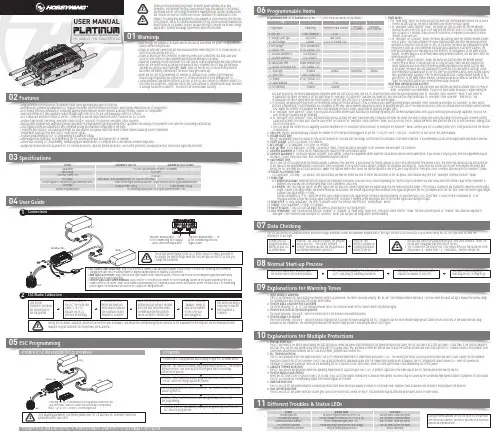
0103Specifications04User Guide05ESC Programming06Programmable Items07Data CheckingProgrammable Item List of Platinum 60A V4 ESC. (“*” in the form below indicate factory defaults. )USER MANUALHV 130A V4 / HV 130A OPTO V4Brushless Electronic Speed Controller1. Flight Mode:1.1 In “Fixed-wing” mode, the motor will start up when the throttle amount reaches 5% or above. There is no soft start-up, the motor responds to the throttle increase rapidly.1.2 In “Helicopter (Linear Throttle)” mode, the motor will start up when the throttle amount reaches 5% and it will start up in a soft way with the throttle (from 0 to 100%) acceleration time is fixed to 3.5 seconds. It will accelerate to the RPM corresponds to the specific throttle amount at the fixed rate.1.3 In “Helicopter (Elf Governor)” mode, the motor will start up when the throttle amount reaches 40% or above. And it will complete the speed standardization and enter the speed-governing operation in the preset start-up time (4~25s). In this mode, the motor will standardize its speed every time it starts up. Due to different discharge rates/capabilities of different batteries, the RPM you standardize each time may be a little different. In consequence, at the same throttle amount, the RPM may be a bit different when using different batteries, but this won’t affect the speed-governing effect.1.4 In “Helicopter (Store Governor)” mode, the motor will start up when the throttle amount reaches 40% or above. It will also start up in a very soft way. And it will also complete the speed standardization and enter the speed-governing operation in the preset start-up time. In this mode, the motor will only standardize its speed the first time when it starts up. When performing RPM standardization for the first time, we recommend using a fully-charged battery with good discharge capability. After the RPM standardization, change another battery to fly your aircraft. At the same throttle amount, the RPM should be the same as the RPM of the first flight. For consistent control feel, we recommend using this mode. About RPM Standardization & OthersI. The motor will enter the soft start-up when user switches the throttle amount from 0 to 40% or above (50%throttle is recommended). The pitch of main blades should be 0 degree during the• High performance microprocessor for excellent motor speed-governing and super soft start-up.• Microprocessor powered by independent DC regulator has better anti-interference performance, which greatly reduces the risk of losing control.• DEO (Driving Efficiency Optimization) Technology adopted greatly improves throttle response & driving efficiency, reduces ESC temperature.• New switch-mode BEC with adjustable output voltage ranges from 5V to 8V and continuous/peak current of 10A/25A.• BEC is separated from other circuits of the ESC, it will keep its normal output when the MOSFET board of the ESC is burnt. • Multiple flight modes: Fixed-wing, Helicopter (Linear Throttle), Helicopter (Elf Governor),Helicopter (Store Governor).• New governor program with adjustable governor parameter P/I brings excellent speed-governing effect, guarantees the stability of the propeller’s revs when the load changes dramatically. • Data logging records the standardized RPM, minimum voltage and maximum temperature of the flight.• "Restart in auto rotation" can manually interrupt the auto rotation and quickly restart the motor to avoid crashes caused by incorrect operations. • Independent output port for RPM (that is: motor speed) signals.• Separate programming port for ESC programming or parameter setting.• WIFI module (sold separately) for programming the ESC wirelessly with your smart phone (IOS or Android).• Online data checking, ESC programming, firmware upgrade (Multifunction LCD program box or WIFI Express is needed) supported.• Multiple protections like start-up protection, ESC thermal protection, capacitor thermal protection, over-current protection, overload protection, and throttle signal loss protection.Model Applications Input Voltage Cont./Peak Current (10s)BEC OutputThrottle Signal/BEC Output/RPM Signal Transmission WiresSize/WeightSeparate Programming PortPlatinum HV 130A V4White Throttle Signal Wire/Red & Black BEC Output Wires/Yellow RPM Signal Transmission WireFor connecting Multifunction LCD Program Box/WIFI module or fanSwitch-mode, 5V-8V Adjustable (Step:0.1V), 10A/25A Cont./Peak101x45.5x27mm / 168.5gProgrammingConnect the LCD program box and a battery to your ESC as shown above.successfully connected to your ESC.relates to the ESC.main blades =R ÷ Motor Poles ÷ 2 ÷ Gear Ratio × Throttle Amount (%).channel on the VBAR system. About which channel you should plug it in, it depends on your receiver and flybarless system. The White wire is for transmitting Program Your ESC with a WIFI Express: For detailed information, please refer to the user manual of WIFI Express.The ESC will record the standardized RPM, minimum voltage, maximum current and maximum temperatures of the flight but won’t save these data, so you need to keep the ESC on if you want to check theinformation of the flight.08Normal Start-up ProcessTurn on the transmitter, and then move the throttle stick to the bottom position.After connected to a battery, the ESC will emit “♪123” indicating it’s normally powered on.The motor will emit several beeps to indicate the number of LiPo cells.The motor emits a long beep indicating the ESC is ready to go.09Explanations for Warning Tones1. Input voltage is abnormal:The ESC will measure the input voltage the moment when it’s powered on. The motor will keep beeping “BB, BB, BB” (the interval between two BBs is 1 second) when the input voltage is beyond the normal range. The warning tone won’t stop until the voltage turns normal. 2. Throttle signal loss protection is activated:The motor will beep “B-, B-, B-” (the interval between two B-s is 2 seconds) when the ESC doesn’t detect any throttle signal. 3. Throttle stick is not at the bottom position:The motor will beep “B-B-B-B-B-” when the throttle stick is not moved to the bottom position.4. Throttle range is to narrow:The motor will beep “B-B-B-B-B-” when the throttle range you set is too narrow (when designing this ESC, it requires that the entire throttle range you set cannot be less than 50% of the whole throttle range available on the transmitter.) The warning tone indicates the throttle range you set is void and you need to set it again.10Explanations for Multiple Protections11Different Troubles & Status LEDs1. Start-up Protection:The ESC will monitor the motor speed during the start-up process. When the speed stops increasing or the speed increase is not stable, the ESC will take it as a start-up failure. At that time, if the throttle amount is less than 15%, the ESC will automatically try to restart up; if it is larger than 15%, you need to move the throttle stick to back the bottom position and then restart up the ESC. (Possible causes of this problem: poor connection/ disconnection between the ESC and motor wires, propellers are blocked, etc.)2. ESC Thermal Protection:The ESC will gradually reduce the output but won’t cut it off completely when the ESC temperature goes above 110℃. For ensuring the motor can still get some power and won’t cause crashes, so the maximum reduction is about 50% of the full power. The ESC will gradually resume its maximum power after the temperature lowers down. In addition, the ESC temperature cannot exceed 70℃ when it’s powered on. Otherwise, it cannot be started up. (Here we are describing the ESC’s reaction in soft cutoff mode, while if in hard cutoff mode; it will immediately cut off the power.) 3. Capacitor Thermal Protection:The ESC will activate this protection when the operating temperature of capacitors goes over 130℃. It protects capacitors in the same way as the ESC thermal protection does to the ESC .4. Throttle Signal Loss Protection:When the ESC detects loss of signal for over 0.25 second, it will cut off the output immediately to avoid an even greater loss which may be caused by the continuous high-speed rotation of propellers or rotor blades. The ESC will resume the corresponding output after normal signals are received. 5. Overload Protection:The ESC will cut off the power/output or automatically restart itself when the load suddenly increases to a very high value. (Possible cause to sudden load increase is that propellers are blocked.)6. Over-current Protection:The ESC will cut off the power when the current gets close to the short circuit current (of 400A). This protection may be activated by the burnt motor or some others.soft start-up process, the RPM standardization completes when the soft start-up ends, and the ESC makes the motor enter the speed-governing state. In “Helicopter (Store Governor)” mode, if user wants to re-standardize the speed, he needs to set the flight mode to “Helicopter (Elf Governor)” and save this mode first, and then reset the flight mode back to “Helicopter (Store Governor)”, then the ESC will re-standardize the motor speed when the motor rotates for the first time after the ESC is powered off and then on again.II. For ensuring the speed-governing effect, we recommend setting the throttle amount to 85% or below in both speed-governing modes (Helicopter (Store Governor) & Helicopter (Elf Governor)), so there will besufficient compensating room to maintain the consistency of the RPM. We recommend replacing the motor or adjusting the gear ratio if the expected RPM still cannot be reached when the throttle amount exceeds 85%. (Note: You need to re-standardize the RPM after replacing the motor, blades, body frame or adjusting the gear ratio.)III. In “Helicopter (Store Governor)” mode, if you fly your aircraft with another pack that has poor discharge capability after the RPM standardization (with a pack which has good discharge capability), the pack has poor discharge capability will get damaged.IV. In “Helicopter (Store Governor)” mode, different battery packs can bring the same stable RPM only if they have the same cell count. This won’t change even when you change the battery pack. However, battery packs with different cell count don’t have the same effect. For instance, in “Helicopter (Store Governor)” mode, you can not use a 4S to calibrate the motor RPM and then use a 6S to drive the motor, hoping it can run at the same RPM.V. User can decide the control feel via adjusting Governor Parameter P/I. In “Helicopter (Store Governor) or Helicopter (Elf Governor)” mode, connect your ESC to a smart phone or PC, then you can check the throttle vs speed chart.2. LiPo Cells: The ESC will automatically calculate the number of LiPo cells you have plugged in as per the “3.7V/Cell” rule if “Auto Calc.” is selected. Or user can set this item manually. 3. Voltage Cutoff Type:The ESC will gradually reduce the output to 50% of the full power in 3 seconds after the voltage cutoff protection is activated, if soft mode is selected . It will immediately cut off all the output when hard mode is selected. 4. Cutoff Voltage: 2.8V-3.8V (custom), 3.0V (default).5. BEC Voltage: 5-8V (adjustable), 0.1V (step), 6V (default).6. Start-up Time: 4-25s (adjustable), 1s (step), 15s (default). (Note: It only functions in Helicopter (Store Governor) and Helicopter (Elf Governor))7. Governor Parameter P: Control the ESC maintaining the stability of the current motor speed.8. Governor Parameter I: Control the dynamic response. To be specific, control the supplement extent when the actual motor speed is below expectation. If you choose a very big value, then the supplement may be too much. If select a very small value, then the supplement may not sufficient.9. Auto Restart Time:the ESC will cut off its output when the throttle amount is between 25% and 40%. If you increase the throttle amount to above 40% within preset time period (0-90s), the motor will rapidly start up and accelerate to the speed (in the programmed Restart Acceleration Time) corresponds to the specific throttle amount, complete the shutdown and restart up . If you move the throttle stick to over 40% beyond the preset time period, the ESC will enter the soft start-up process. (Note: This function won’t effect unless the throttle amount is over 25% and it only effects in “Helicopter (Store Governor) and Helicopter (Elf Governor)” mode.)10. Restart Acceleration Time:1-3s (adjustable), 0.5s (step), 1.5s (default). This item controls the time the motor will cost to restart and accelerate to the full speed. (This function only effects in “Helicopter Governor Elf/Store” mode) 11. Brake Type:11.1 Proportional Brake: when the throttle range on the transmitter is between 20% and 100%, the corresponding ESC throttle output is between 0% and 100%.When the throttle range on the transmitter is between 20% and 0%, the corresponding brake force is between 0 and 100%.11.2 Reverse: after selecting this option, the RPM signal wire will turn into a reverse signal wire (the signal range is in line with the throttle range). After setting a channel on the transmitter, when the reverse signal length is above 20% signal length, the Reverse mode will be activated. The reverse signal length must be below 20% signal length when the ESC is powered on for the first time. When the reverse signal length is below 20% signal length, 0-100%throttle corresponds to “CW”; when the reverse signal length is above 20% signal length, the motor will stop spinning CW (and then spin CCW); at this time, 0-100% throttle corresponds to “CCW”. Any signal loss will activate the throttle signal loss protection, no matter it happens to the RPM signal wire or the throttle signal cable during the flight.12. Brake Force: 0-100% (adjustable), 1% (step), 0 (default). (Note: this function only effects in “Normal Brake” mode.)13. Timing: 0-30° (adjustable), 1° (step), 15° (default).14. Motor Rotation: CW/CCW. User can adjust this item via a multifunction LCD program box.15. DEO (Freewheel): User can decide this function “Enabled” or “Disabled” in “Fixed Wing” mode or in “Helicopter (Linear Throttle)” mode. This item has been preset to “Enabled” and cannot be adjusted in “Helicopter (Store Governor) and Helicopter (Elf Governor)” mode. This function can brings better throttle linearity.During the normal operation, the Blue LED on the ESC will turn solid after the start-up completes. The Red LED will come on at full throttle and dies out at partial throttle.。
MMT-220 D R20-35AL 直流驱动器使用说明书济南科亚电子科技有限公司MMT-220DR系列直流马达驱动器采用可控硅斩波形式具有独特的触发方式,使其更加准确、可靠。
该驱动器是结合国际标准要求,吸收先进的技术经验,并研制生产的换代调速产品,其优异的性能、可靠的质量、具有高性价比。
(既是在无速度反馈时也能达到高调速比)也是直流马达驱动领域的佼佼者。
目前该系列部分产品已销往多个国家。
并在国内的塑料机械. 食品机械. 线缆设备. 机械加工. 造纸. 印刷. 试验设备.化验室设备.搅拌设备等领域得到广泛应用。
一、产品特点■采用SMT技术体积小■适用于永磁式、他励式和直流力矩马达■双闭环P I调节(电压电流)■电流设置和限流保护■涨力模式和速度模式选择■低速力矩大■快速停止功能■上限. 下限速度任意设置■软启动软停止设置功能■标准信号输入0 — 5V 或 10K 电位器■可实现远程启停跟随性好.响应速度快■调速比宽机械特性硬二.技术参数□输入电压AC:110V / 220V±10﹪。
□频率: 50/60HZ±5﹪。
□输出电压DC:0~90V 0-110V . 0-160V 0-180V 0-220V (可以设定)□额定励磁电流: ﹙DC100V或200V﹚ 3A□额定输出电流:6A 8A 10A 20A 30A 35A□转速调速比: 1:100□输出电压精度: ≤0.1﹪□环境温度: -10℃- +60℃□环境湿度: 相对湿度在≤80﹪。
﹙无结露﹚三、产品性能:1.具有较硬的机械特性,静差率1%。
2.具有较宽的调速范围,(0—最大)。
3.具有较快的动态响应过程。
4.具有加、减速时自动平滑的过渡过程。
5.较好的挖土机特性,能将过载电流自动限制在设定值电流上。
6.可靠性高,结构紧凑,具有极高的性价比。
四、电位器调整说明:1、最高转速限制:MAX SPD将给定电位器调整到最大,然后调整 MAX SPD电位器,可限制马达的最高输出转速。
感谢您购买本产品!无刷动力系统功率强大,错误的使用可能造成人身伤害和设备损坏。
我们强烈建议您在使开关机及鸣音说明2· 电调与相关连接部件连接前,请确保所有电线和连接部件绝缘良好,短路会毁坏电调。
· 请务必仔细连接好各部件,若连接不良,您可能不能正常控制赛车,或出现设备损坏等其他不可预知的情况。
· 使用此电调前,请认真查看各动力设备以及车架说明书,确保动力搭配合理,避免因错误的动力搭配导致电机超载,最终损坏电调。
· 高速运行中,因车子轮胎会“膨”到极致,故而请勿将车子腾空然后扣全油门,否则,轮胎运行故障会引起严重伤害。
· 勿使电调外部温度超过90℃/194℉,高温将会毁坏电调并且可能导致电机损坏。
· 使用完毕后,切记断开电池与电调的连接。
只要接着电池,即使开关未开电调也会一直消耗电流,长时间连接会导致电池最终完全放电;进而导致电池或电调出现故障;我们不对因此而造成的任何损害负责。
开关机说明:关机状态下短按ON/OFF键开机;开机状态下长按ON/OFF键关机。
开机鸣音说明:在正常情况下开机, 电机会发出几声“哔”鸣音表示锂电节数。
例如:“哔哔-”表示2节锂电,“哔哔哔-”表示3节锂电。
最后鸣叫一声长音“哔—”表示自检完成。
备注:电机鸣叫的同时,电调灯同步闪烁。
编程项目说明3下表中黑底白字的选项为可编程项目的默认值。
编程方法402注意事项1. 利用LED参数设定卡进行参数设置:VALUE”按键即可快速选择参数项和参数值,然后按“OK”键保存参数。
2. 利用LCD G2设定盒进行参数设置:此电调支持使用多功能LCD G2设定盒进行参数设置,且支持通过LCD G2设定盒连接到电脑进行参数设置和固件升级。
用一条两端带JR公头的排线将电调与LCD G2设定盒连接起来,然后给电调上电,LCD G2设定盒将显示出开机界面,按LCD G2设定盒上任意按键可进入到参数界面,使用“ITEM”和“VALUE”按键即可更改参数设定,按“OK(R/P)”按键保存参数设置。
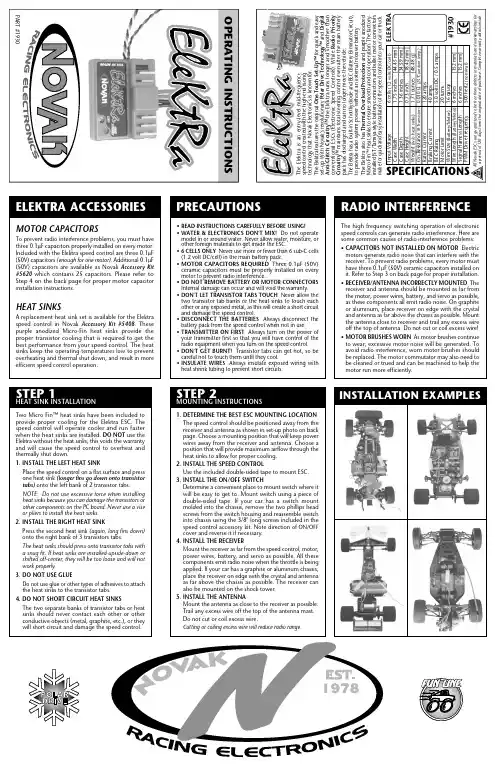
T h e E l e k t r a i s a n e n t r y -l e v e l m i d -f r e q u e n c y s p e e d c o n t r o l c r e a t e d w i t h t h e h i g h -e n d r a c i n g t e c h n o l o g y t h a t N o v a k E l e c t r o n i c s i s k n o w n f o r .S e t -U p ™ f o r q u i c k a n d e a s y ELEKTRA ACCESSORIESMOTOR CAPACITORSTo prevent radio interference problems, you must have F capacitors properly installed on every motor.Included with the Elektra speed control are three 0.1µF (enough for one motor). Additional 0.1µF (50V) capacitors are available as Novak Accessory Kit which contains 25 capacitors. Please refer to Step 4 on the back page for proper motor capacitor A replacement heat sink set is available for the Elektra Accessory Kit #5408. These purple anodized Micro-Fin heat sinks provide the proper transistor cooling that is required to get the best performance from your speed control. The heat operating temperatures low to prevent overheating and thermal shut down, and result in more efficient speed control operation.PRECAUTIONSREAD INSTRUCTIONS CAREFULLY BEFORE USING!WATER & ELECTRONICS DON'T MIX! Do not operate model in or around water. Never allow water, moisture, or other foreign materials to get inside the ESC.Never use more or fewer than 6 sub-C cells (1.2 volt DC/cell) in the main battery pack.MOTOR CAPACITORS REQUIRED Three 0.1µF (50V)ceramic capacitors must be properly installed on every to prevent radio interference.DO NOT REMOVE BATTERY OR MOTOR CONNECTORS Internal damage can occur and will void the warranty.DON'T LET TRANSISTOR TABS TOUCH Never allow the two transistor tab banks or the heat sinks to touch each other or any exposed metal, as this will create a short circuit DISCONNECT THE BATTERIES Always disconnect the pack from the speed control when not in use.Always turn on the power ofGround / motor can2.CONNECT SPEED CONTROL TO THE RECEIVERPlug the speed control into the THROTTLE CHANNEL of the receiver.3.CONNECT SPEED CONTROL TO THE BATTERY PACKPlug the white JST connector from the speed control into the JST/Tamiya style connector on a fully charged6 cell battery pack (1.2 volts DC/cell)negative (-) and the red wire is positive (4.CONNECT SPEED CONTROL TO THE MOTORPlug the bullet connector on the red wire (speed control to motor positive. Plug the other bullet connector, on the blue wire (-), to motor negative.Removing or changing the battery or motor connectors may cause internal ESC damage and will void the warranty. USE ONLY STOCK & MILD MODIFIED MOTORS (20 or more turns only!) with the Elektra speed control––Using hotter motors and lower gear ratios will cause the speed control to overheat.TIP: Twisting the BLUE & RED motor wires one or two times around each other as they go to motor can help reduce any radio noise that may be emitted from the power wires. Refer to Set-Up photo.5.OPTIONAL USE OF SCHOTTKY DIODEThe Elektra does not require an external Schottky diode.However, using one will increase the efficiency and reduce the operating temperature of the ESC.Solder the lead CLOSEST to the silver stripe on the body of the Schottky diode to the POSITIVESolder the lead OPPOSITE the silver stripe on the body of the Schottky to the NEGATIVE (-) motor tab.Schottky diodes are available in Novak kit #5640.If installed backwards, a Schottky diode will be destroyed. The body of a bad diode will normally crack open. Replace only with diodes that have a minimum rating of 35 volts / 8 amps.CUSTOMER SERVICECUSTOMER SERVICE HOURS (PST)Monday-Thursday:8:00am-5:00pmFriday:8:00am-4:00pm (closed every other Fri.)(949) 833-8873 • FAX (949) 833-1631©1999 Novak Electronics, Inc. • All Rights ReservedNo part of these operating instructions may be reproduced without thewritten permission of Novak Electronics, Inc.All Novak speed controls are designed and manufactured in the U.S.A.Elektra™, Polar Drive Technology™, Radio Priority Circuitry™, One-Touch Set-Up™, and Digital Anti-Glitch Circuitry™ are all trademarks ofNovak Electronics, Inc.Printed in the U.S.A. 11/99 • #IM-1930-1blue wire(motor negative)red wire(motor positive)Trail excess wireoff antenna mast.(Do not cut or coil)Tip: Twist motor wiresto reduce radio noise!Keep receiverand antennaaway frommotor, servo,battery, andpower wires.red wire(battery positive)black wire(battery negative)(-)(+)Mount switchwhere it will beeasy to get to.(-)(+)Extra 0.1µF capacitorsavailable in Novak kit #5620.NOVAK ELECTRONICS, INC.18910 Teller AvenueIrvine, CA 92612motor with20 or moreturns6 cellbatterypack。
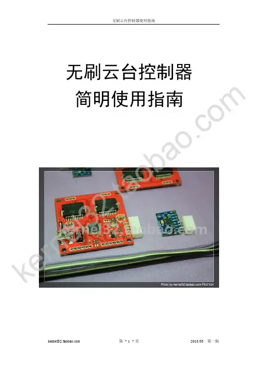
无刷云台控制器简明使用指南k e r ne l32.t ao ba o.c om使用和安全须知感谢您选用本店出品的无刷云台控制器。
本控制器是根据德国开源无刷云台项目提供图纸制作,使用的也是开源的代码,项目链接/p/brushless-gimbal/。
目前提供的硬件版本为V1.1版,烧录的固件版本号为V044,玩家可根据需要自行上项目网站下载更新固件。
目 录1、控制器及配件 P32、控制器接线图 P33、调参工具介绍 P44、编译烧录固件 P6 4.1 arduino 编译器设置 P6 4.2固件修改 P9小贴士:控制连接计算机调参和烧录固件,需要连接电池,不然仅靠USB 供电不足。
目前比较稳定的固件是V004版本,建议不着急升级。
ke rn el 32.t a ob ao .c o m1、控制器及配件。
本店出售的控制包含主控、传感器、传感器连接线。
主控和传感器接口使用XH2.54插座,配套XH2.54 4P转5P线。
2.控制器接线图。
电源输入可以支持最大4S电池,手动俯仰控制接A1,手动横滚控制接A2,上方的2组3P 针脚分别接2个电机的三相线。
(4S下电机发热严重,慎用)k e r ne l32.t ao ba o.c om3.调参工具介绍。
目前店主根据需要汉化了3个调参工具,所有程序均可在QQ群236284685的群共享内下载。
下图为第三方调参工具,支持V044以上固件。
“定义”模块是用来修改固件源码definitions.h 文件中有关电机的配置参数,修改保存后需要重刷固件方能生效。
其中“默认Adress”需修改为LOW,电机才能正常工作(后面关于代码修改也是改这个参数)。
下图为汉化后的官方调参工具,支持到V044固件。
k e r ne l32.t ao ba o.c om下图为官方调参程序V046版,支持V046B 固件。
小贴士:调参程序设计的是最大支持检测到COM15端口,但经过使用,发现不少玩家需要把控制器的COM 口修改为COM5或COM6方能检测到,建议如果调参程序无法连接控制器,不妨将COM 口修改到COM6以下。
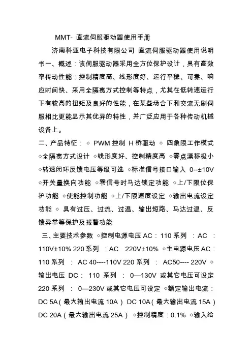
MMT- 直流伺服驱动器使用手册济南科亚电子科技有限公司直流伺服驱动器使用说明书一、概述:该伺服驱动器采用全方位保护设计,具有高效率传动性能:控制精度高、线形度好、运行平稳、可靠、响应时间快、采用全隔离方式控制等特点,尤其在低转速运行下有较高的扭矩及良好的性能,在某些场合下和交流无刷伺服相比更能显示其优异的特性,并广泛应用于各种传动机械设备上。
二、产品特征:◇PWM控制H桥驱动◇四象限工作模式◇全隔离方式设计◇线形度好、控制精度高◇零点漂移极小◇转速闭环反馈电压等级可选◇标准信号接口输入0--±10V ◇开关量换向功能◇零信号时马达锁定功能◇上/下限位保护功能◇使能控制功能◇上/下限速度设定◇输出电流设定功能◇具有过压、过流、过温、输出短路、马达过温、反馈异常等保护及报警功能三、主要技术参数◇控制电源电压AC:110系列:AC :110V±10% 220系列:AC :220V±10% ◇主电源电压AC:110系列:AC 40----110V 220系列:AC50---- 220V ◇输出电压DC:110系列:0—130V或其它电压可设定220系列:0—230V或其它电压可设定◇额定输出电流:DC 5A(最大输出电流10A)DC 10A(最大输出电流15A)DC 20A(最大输出电流25A)◇控制精度:0.1% ◇输入给定信号:0—±10V ◇测速反馈电压:7V/1000R 9.5V/1000R 13.5V/1000R 20V/1000R 可经由PC板内插片选定并可接受其它规格订制四、安装环境要求:◇环境温度:-5oC ~ +50oC ◇环境湿度:相对湿度≤80RH。
(无结露)◇避免有腐蚀气体及可燃性气体环境下使用◇避免有粉尘、可导电粉沫较多的场合◇避免水、油及其他液体进入驱动器内部◇避免震动或撞击的场合使用◇避免通风不良的场合使用五、电源输入说明该驱动系统分两路电源输入:即U1、V1为主电源输入,U2、V2为控制电源输入。
无刷驱动器D B L S-02一概述:本控制驱动器为闭环速度型控制器,采用最近型IGBT和MOS功率器,利用直流无刷电机的霍尔信号进行倍频后进行闭环速度控制,控制环节设有PID速度调节器,系统控制稳定可靠,尤其是在低速下总能达到最大转矩,速度控制范围150~10000rpm。
二产品特征:1、PID速度、电流双环调节器2、高性能低价格3、20KHZ 斩波频率4、电气刹车功能,使电机反应迅速5、过载倍数大于2,在低速下转矩总能达到最大6、具有过压、欠压、过流、过温、霍尔信号非法等故障报警功能三电气指标标准输入电压:24VDC~48VDC,最大电压不超过60VDC。
最大输入过载保护电流:15A、30A两款连续输出电流:15A加速时间常数出厂值:0.2秒其他可定制四端子接口说明:1、电源输入端:GND:信号地F/R:正、反转控制,接GND反转,不接正转,正反转切换时,应先关断ENEN:使能控制:EN接地,电机转(联机状态),EN不接,电机不转(脱机状态)BK:刹车控制:当不接地正常工作,当接地时,电机电气刹车,当负载惯量较大时,应采用脉宽信号方式,通过调整脉宽幅值来控制刹车效果。
SV ADJ:外部速度衰减:可以衰减从0~100%,当外部速度指令接6.25V时,通过该电位器可以调速试机PG:电机速度脉冲输出:当极对数为P时,每转输出6P个脉冲(OC门输入)ALM:报警输出:当电路处于报警状态时,输出低电平(OC门输出)+5V:调速电压输出,可用电位器在SV和GND形成连续可调内置电位器:调节电机速度增益,可以从0~100%范围内调速。
五驱动器与无刷电机接线图六机械安装:七功能与使用调速方式本驱动器提供以下两种调速方式用户可任选一种:内部电位器调速:逆时针旋转驱动器面板上的电位器电机转速减小,顺时针则转速增大。
用户使用外部输入调速时必须将电位器设于最小状态。
外部输入调速将外接电位器的两个固定端分别接于驱动器的GND和+5v一端,将调节端接于SV端即可使用外接电位器(10K~50K)调速,也可以通过其它的控制单元(如PLC、单片机等)输入模拟电压到SV端实现调速(相对于GND),SV端口的接受范围为DCOV~+5V,对应电机转速为0~额定转速。
NMB24-MFTBasic Non Fail-Safe multifunction technologyactuator for controlling dampers in typical commercial HVAC applications.• Torque motor 90 in-lb [10 Nm]• Nominal voltage AC/DC 24 V • Control MFT/programmable • Position feedback 2...10 VTechnical dataElectrical dataNominal voltageAC/DC 24 V Nominal voltage frequency 50/60 HzNominal voltage rangeAC 19.2...28.8 V / DC 21.6...28.8 V Power consumption in operation 3.5 W Power consumption in rest position 1.3 W Transformer sizing 6 VAElectrical Connection18 GA plenum cable with 1/2" conduitconnector, degree of protection NEMA 2 / IP54, 1 m 3 m and 5 mOverload Protectionelectronic throughout 0...95° rotation Functional dataTorque motor 90 in-lb [10 Nm]Operating range Y 2...10 VOperating range Y note 4...20 mA w/ ZG-R01 (500 Ω, 1/4 W resistor)Input impedance100 kΩ for 2...10 V (0.1 mA), 500 Ω for 4...20 mA, 1500 Ω for PWM, On/Off and Floating point Operating range Y variable Start point 0.5...30 V End point 2.5...32 VOperating modes optional variable (VDC, PWM, on/off, floating point)Position feedback U 2...10 V Position feedback U note Max. 0.5 mA Position feedback U variable VDC variableDirection of motion motor selectable with switch 0/1Manual override external push button Angle of rotation Max. 95°Angle of rotation note adjustable with mechanical stop Running Time (Motor)150 s / 90°Running time motor variable 45...170 s Noise level, motor 45 dB(A)Position indicationMechanical, 30...65 mm stroke Safety dataPower source ULClass 2 Supply Degree of protection IEC/EN IP54Degree of protection NEMA/UL NEMA 2Enclosure UL Enclosure Type 2Agency ListingcULus acc. to UL60730-1A/-2-14, CAN/CSA E60730-1:02CE acc. to 2014/30/EU and 2014/35/EU Quality Standard ISO 9001UL 2043 CompliantSuitable for use in air plenums per Section 300.22(C) of the NEC and Section 602 of the IMCNMB24-MFTFootnotesApplicationOperationTypical specificationSafety dataAmbient humidity Max. 95% RH, non-condensingAmbient temperature -22...122°F [-30...50°C]Storage temperature -40...176°F [-40...80°C]Servicingmaintenance-free Weight Weight2.2 lb [1.0 kg]MaterialsHousing material UL94-5VA†Rated Impulse Voltage 800V, Type action 1, Control Pollution Degree 3.Product featuresFor proportional modulation of dampers in HVAC systems. Actuator sizing should be done in accordance with the damper manufacturer’s specifications.The actuator is mounted directly to a damper shaft up to 1.05" in diameter by means of its universal clamp. A crank arm and several mounting brackets are available for applications where the actuator cannot be direct coupled to the damper shaft.The default parameters for 2...10 V applications of the ..MFT actuator are assigned duringmanufacturing. If necessary, custom versions of the actuators can be ordered. The parameters can be changed by two means: pre-set and custom configurations from Belimo or on-site configurations using the Belimo PC-Tool software.The actuator is not provided with and does not require any limit switches, but is electronically protected against overload. The anti-rotation strap supplied with the actuator will prevent lateral movement.The NMB(X) series provides 95° of rotation and a visual indicator indicates position of theactuator. When reaching the damper or actuator end position, the actuator automatically stops. The gears can be manually disengaged with a button on the actuator cover.The NMB(X)24-MFT actuators use a brushless DC motor, which is controlled by an Application Specific Integrated Circuit (ASIC). The ASIC monitors and controls the actuator’s rotation and provides a digital rotation sensing (DRS) function to prevent damage to the actuator in a stall condition. Power consumption is reduced in holding mode.Add-on auxiliary switches or feedback potentiometers are easily fastened directly onto the actuator body for signaling and switching functions.Proportional control damper actuators shall be electronic direct-coupled type, which require no crank arm and linkage and be capable of direct mounting to a shaft from 1/4" to 1/2" diameter. Actuators must provide proportional damper control response to a 2 to 10 VDC or, with the addition of a 500Ω resistor, a 4 to 20 mA control input from an electronic controller orpositioner. Actuators shall have brushless DC motor technology and be protected from overload at all angles of rotation. Actuators shall have manual override on the cover. Run time shall be constant and independent of torque. Actuators shall be cULus listed, have a 5-year warranty, and be manufactured under ISO 9001 International Quality Control Standards. Actuators shall be as manufactured by Belimo.AccessoriesElectrical accessoriesDescriptionType Auxiliary switch 1 x SPDT add-on S1A Auxiliary switch 2 x SPDT add-onS2AFeedback potentiometer 10 kΩ add-on, grey P10000A GR Feedback potentiometer 1 kΩ add-on, grey P1000A GR Feedback potentiometer 140 Ω add-on, grey P140A GR Feedback potentiometer 2.8 kΩ add-on, grey P2800A GR Feedback potentiometer 5 kΩ add-on, grey P5000A GR Feedback potentiometer 500 Ω add-on, grey P500A GR Positioner for wall mountingSGA24Resistor, 500 Ω, 1/4" wire resistor with 6" pigtail wires ZG-R01Battery backup system, for non-spring return models NSV24 US Transformer, AC 120 V to AC 24 V, 40 VAZG-X40NMB24-MFTMechanical accessories Description TypeShaft clamp reversible, clamping range ø8...20 mm K-NAMounting bracket for AF..ZG-100Mounting bracket ZG-101Mounting bracket ZG-103Mounting bracket ZG-104Mounting kit for linkage operation for flat installation ZG-NMAShaft extension 240 mm ø20 mm for damper shaft ø8...22.7 mm AV8-25Shaft extension for 1/2" diameter shafts (3.8" L).ZG-NMSA-1Weather shield 13x8x6" [330x203x152 mm] (LxWxH)ZS-100Weather shield 406x213x102 mm [16x8-3/8x4"] (LxWxH)ZS-150Wrench 0.32 in and 0.39 in [8 mm and 10 mm]TOOL-06ZG-JSLLinkage kitJackshaft Retrofit Linkage with Belimo Rotary ActuatorsElectrical installationActuators with appliance cables are numbered.Provide overload protection and disconnect as required.Actuators may also be powered by DC 24 V.Only connect common to negative (-) leg of control circuits.A 500 Ω resistor (ZG-R01) converts the 4...20 mA control signal to 2...10 V.Control signal may be pulsed from either the Hot (Source) or Common (Sink) 24 V line.For triac sink the Common connection from the actuator must be connected to the Hotconnection of the controller. Position feedback cannot be used with a triac sink controller; theactuator internal common reference is not compatible.Actuators may be connected in parallel if not mechanically linked. Power consumption andinput impedance must be observed.IN4004 or IN4007 diode. (IN4007 supplied, Belimo part number 40155).VDC/mA ControlWiring diagramsOn/OffNMB24-MFT Floating Point VDC/mA ControlPWM Control Override ControlDimensions。
· 采用高性能32位ARM微处理器,运行频率高达48MHz;· BLHeli_32固件是在BLHeli(代码)及BLHeli-S(代码)基础上编写的第三代BLHeli(代码)。
· 使用damped light模式。
Damped light不仅能再生制动从而使电机迅速减速,还能同步整流。
· 该版本代码支持各种功能从而防止出现(电机)失步问题,尽管其默认设置在通常运行环境下即能工作良好,但它仍支持多项参数可调节从而使代码即使在最严苛 的情况下也能运行良好。
· 电调可支持普通PWM油门模式,OneShot125油门模式,OneShot42油门模式以及MultShot油门模式;· 电调可支持DShot150/300/600/1200数字油门模式;· 具有导航提示功能,若零油门信号持续一段时间,电调即会发出导航提示音,有效帮助找到丢失的飞行器。
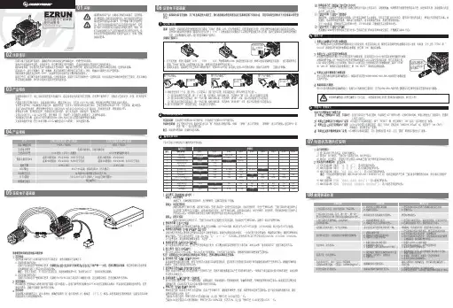
02注意事项03产品特色04产品规格05使用向导01声明XRotor Micro 30A/40A BLHeli_32多旋翼飞行器无刷电子调速器使用说明书· 使用本产品前,请认真查看各动力设备以及飞行器的使用说明书,确保动力搭配合理,避免因错误的动力搭配导致电机超载,最终损坏电调。
· 安装本产品时,由于需要进行焊接,连接等操作,所以请务必确保所有电线和连接部件绝缘良好,短路将会毁坏本产品。
对本产品的相关线材进行焊接操作时, 为保证焊接牢靠,请使用足够功率的焊接设备进行焊接。
若连接不良,您可能不能正常控制飞行器,或出现设备损坏等其他不可预知的情况。
· 使用本产品时请远离不安全因素,如障碍物,人群,高压线等。
请严格按照本手册中规定的工作环境置(如电压,电流,温度等参数)使用,虽然本产品有相关保 护措施,但极限的使用还是有可能会对本产品造成永久性的损坏。
· 使用完毕后,切记将电源切断。
第⼀节⽆刷控制器的线束功能及主要参数第⼀节⽆刷控制器的线束功能及主要参数前期⽆刷控制器粗红线、粗⿊线为电源接⼝,现在新型⽆刷控制器还有⼀根⼩电流锁线,⼀般为细红线或细黄线,具体连接⽅式是:粗红线与电源正极的⼀个接头相连,⼩电流锁线与电源正极的另⼀个通过电源锁的橙⾊接头相连,粗⿊线直接与电源负极线相连。
六芯塑料插接件为电机信号接⼝,细红线为6.25-5伏的参考电源,细⿊线为地线,细黄线、细绿线、细兰线分别为三相霍尔信号线。
九芯塑料插接件为转把与刹把信号接⼝。
细红线:转把与刹把共⽤正极线,与细⿊线电压为5-6伏。
细⿊线:转把与刹把共⽤负极线,与细红线电压为5-6伏。
细黄线:转把调速信号线,与细⿊线电压为1-4.2或4.8伏。
细紫线:刹把刹车断电信号线,与细⿊线电压为5-6伏,不刹车电压为0时是刹车常断电。
以上四种线的颜⾊与功能在所有控制器中都是⼀样的. 在九芯塑料插接件中还有⼀种线为速度表速度信号线,⼀般为兰⾊线,也有是咖啡⾊线。
⽆刷控制器的主要参数额定电压48V⽋压保护值 42±0.5V 过流保护值 15±1A 辅助电源 5.7V调速输⼊电压 1-4.8V正向控制⽅式断电刹车输⼊电⼦低电位⼩电流线:⼩电流线都是与电源锁橙⾊线相连的,⼀般情况为细橙⾊,也有细红⾊,如果将⼩电流线与粗红电源主线交换位置连接则将造成⾃放电现象。
第⼆节⼯作原理及主要元件⽆刷控制器⼯作原理:⽆刷直流电机中的位置传感器检测转⼦磁场相对于定⼦绕组的位置,并输出霍尔信号到MC33035,使主控芯⽚MC33035在确定的相对位置上输出六路控制信号,控制信号通过IR2103缓存,控制功率管在转⼦的适当位置导通或截⽌,从⽽控制各电枢绕组的电流,随着转⼦的位置改变按⼀定的顺序进⾏换流,从⽽保证每个磁极下电流⽅向不变,实现了没有电刷的⽆接触式换向。
当刹车、⽋压、过流发⽣时,MC33035的第七脚电压由⾼变低,封锁输出,电机停转。
MMT-AC24DP10BL使用说明书一、 概述:济南MMT系列伺服控制系统、PWM直流调速系统是采用国际最新数字控制调速技术和专用器件,研制生产的高精度电子调速装置,本装置采用国际标准技术规范,各项技术指标均达到国际同类产品的要求。
具有结构简单、体积小、重量轻等优点,可用于SZ系列、ZYT系列、Z2系列功率为几十W~几KW的直流电动机的无级调速。
具有多重保护功能,安全、稳定、可靠。
完全可兼容国际同类产品。
国际品质,国产价格。
适用范围:MMT系列直流调速器在机床、造纸印刷、纺织印染、光缆线缆设备、包装机械、电工机械、食品加工机械、橡胶机械、生物设备、印制电路板设备、实验设备、焊接切割、轻工机械、物流输送设备、机车车辆、医疗设备、通讯设备等行业广泛应用。
二、产品性能:1.具有较硬的机械特性,静差率1%。
2.具有较宽的调速范围,(0—最大)。
3.具有较快的动态响应过程。
4.具有加、减速时自动平滑的过渡过程。
5.较好的挖土机特性,能将过载电流自动限止在设定值电流上。
6.可靠性高,结构紧凑,具有极高的性价比。
三、产品特点:1.调速比1:100 (开环)2.低速启动力矩大3.PWM脉宽调制技术,噪音低4.双闭环P I 调节5.电流设置、限流保护、过流报警功能6.软启、软停时间设置功能7.跟随性好响应速度快8.闭锁控制功能(接通工作,断开停止工作)9.标准信号接口(另配信号隔离器后可用于模拟量控制0-5V、0-10V或4—20mA)10.短路保护功能四、主要技术参数1.输入电压:AC 24V±10%2.输出电压:DC 0~24V或其它电压可设定3.输出电流:DC 10A4.额定励磁电压/电流:DC 24V(12V)/3A 5.电位器(10K/2W)调整6.环境温度:-10 ºC~+60ºC7.环境湿度:相对湿度≤80RH(无结露)五、电位器调整说明1.电流限制调整:TORQUE可以限制驱动板最大输出电流,根据所选马达的额定电流调整该电位器,使驱动板的最大输出电流为马达额定电流的120%~200%。