西门子小型断路器样本12
- 格式:pdf
- 大小:3.12 MB
- 文档页数:28
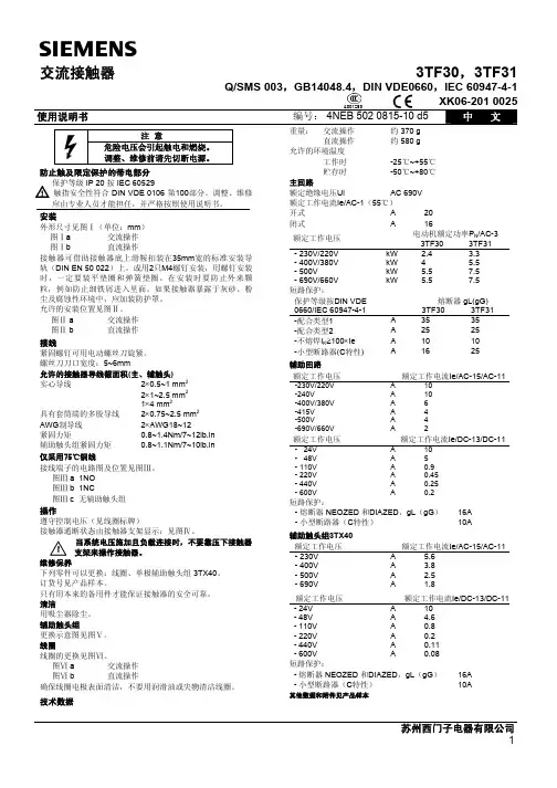
交流接触器3TF30,3TF31Q/SMS 003,GB14048.4,DIN VDE0660,IEC 60947-4-1XK06-201 0025 使用说明书编号: 4NEB 502 0815-10 d5中 文A001253注 意危险电压会引起触电和燃烧。
调整、维修前请先切断电源。
防止触及限定保护的带电部分保护等级 IP 20 按 IEC 60529! 触指安全性符合 DIN VDE 0106 第100部分。
调整、维修应由专业人员才能担任,并严格按照使用说明书。
安装外形尺寸见图Ⅰ(单位:mm ) 图Ⅰa 交流操作 图Ⅰb 直流操作接触器可借助接触器底上滑鞍扣装在35mm 宽的标准安装导轨(DIN EN 50 022)上。
或用2只M4螺钉安装,用螺钉安装时,一定要装平垫圈和弹簧垫圈。
在安装时要防止外来颗粒,例如防止细铁屑进入里面。
如果接触器暴露于灰砂、粉尘及腐蚀性环境中,应加装防护罩。
允许的安装位置见图Ⅱ。
图Ⅱ a 交流操作 图Ⅱ b 直流操作接线紧固螺钉可用电动螺丝刀旋紧。
螺丝刀刀口宽度:5~6mm允许的接触器导线截面积(主、辅触头) 实心导线 2×0.5~1 mm 2 2×1~2.5 mm 21×4 mm 2具有套筒端的多股导线 2×0.75~2.5 mm 2 AWG 制导线 2×AWG18~12 紧固力矩 0.8~1.4Nm/7~12lb.in 辅助触头组紧固力矩 0.8~1.1Nm/7~10lb.in 仅采用75℃铜线接线端子的电路图及位置见图Ⅲ。
图Ⅲ a 1NO 图Ⅲ b 1NC图Ⅲ c 无辅助触头组操作遵守控制电压(见线圈标牌)接触器通断状态由接触器支架显示:见图Ⅳ。
当系统电压施加且负载连接时,不要靠压下接触器支架来操作接触器。
维修保养下列零件可以更换:线圈、单极辅助触头组 3TX40。
订货号见产品样本。
只有用本来的备用件才能保证接触器的安全可靠。
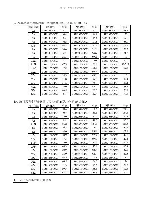
西门子 5SJ6系列微型断路器9、5SJ6系列小型断路器(脱扣特性C型,分断能力6KA)额定电流1级(1P)单价2极(2P)单价3极(3P)单价1A5SJ61017CC20545SJ62017CC20121.75SJ63017CC20181.82A5SJ61027CC2050.45SJ62027CC20116.85SJ63027CC201723A5SJ61037CC20635SJ62037CC20115.65SJ63037CC20157.64A5SJ61047CC2046.55SJ62047CC20107.85SJ63047CC20158.90.5A5SJ61057CC2044.25SJ62057CC20115.65SJ63057CC20162.96A5SJ61067CC2038.65SJ62067CC2091.95SJ63067CC20136.28A5SJ61087CC20425SJ62087CC2094.65SJ63087CC20131.310A5SJ61107CC2028.35SJ62107CC2069.25SJ63107CC2011013A5SJ61137CC20425SJ62137CC2073.65SJ63137CC20115.60.3A5SJ61147CC2047.35SJ62147CC20105.15SJ63147CC20162.91.6A5SJ61157CC2047.35SJ62157CC20105.15SJ63157CC20152.316A5SJ61167CC2028.35SJ62167CC2069.25SJ63167CC2011020A5SJ61207CC2028.35SJ62207CC2069.25SJ63207CC2011025A5SJ61257CC2031.85SJ62257CC2076.15SJ63257CC20119.132A5SJ61327CC2031.85SJ62327CC2076.15SJ63327CC20119.140A5SJ61407CC2038.65SJ62407CC2093.15SJ63407CC20141.850A5SJ61507CC2046.55SJ62507CC20105.55SJ63507CC20158.963A5SJ61637CC20515SJ62637CC20112.45SJ63637CC20170.310、5SJ6系列小型断路器(脱扣特性D型,分断能力6KA)额定电流1级(1P)单价2极(2P)单价3极(3P)单价1A5SJ61018CC2070.45SJ62018CC20160.55SJ63018CC20234.62A5SJ61028CC2070.45SJ62028CC20160.55SJ63028CC20234.63A5SJ61038CC2073.65SJ62038CC20147.15SJ63038CC20210.14A5SJ61048CC20655SJ62048CC20148.35SJ63048CC20216.80.5A5SJ61058CC2066.25SJ62058CC20147.15SJ63058CC20215.46A5SJ61068CC2046.75SJ62068CC201145SJ63068CC20159.68A5SJ61088CC2054.65SJ62088CC2099.85SJ63088CC20162.910A5SJ61108CC2038.95SJ62108CC2092.35SJ63108CC20142.513A5SJ61138CC2047.35SJ62138CC2099.85SJ63138CC20147.10.3A5SJ61148CC2073.65SJ62148CC20147.15SJ63148CC20215.41.6A5SJ61158CC2068.35SJ62158CC20147.15SJ63158CC20215.416A5SJ61168CC2038.95SJ62168CC2092.35SJ63168CC20142.520A5SJ61208CC2038.95SJ62208CC2092.35SJ63208CC20142.525A5SJ61258CC2044.55SJ62258CC20104.95SJ63258CC2015432A5SJ61328CC2044.55SJ62328CC20104.95SJ63328CC2015440A5SJ61408CC2051.35SJ62408CC20119.75SJ63408CC20159.650A5SJ61508CC2059.35SJ62508CC20136.85SJ63508CC20182.463A5SJ61638CC2068.45SJ62638CC20159.65SJ63638CC20210.9 11、5SJ5系列小型直流断路器额定电流1极(1P)单价2极(2P)单价友情提示:1A5SJ51017CC2091.85SJ52017CC20202.62A 5SJ51027CC2090.95SJ52027CC20199.63A 5SJ51037CC2088.85SJ52037CC20195.64A 5SJ51047CC2089.35SJ52047CC20168.10.5A 5SJ51057CC20110.35SJ52057CC20250.16A 5SJ51067CC2079.85SJ52067CC20175.78A 5SJ51087CC2079.85SJ52087CC20150.310A 5SJ51107CC2058.85SJ52107CC20128.713A 5SJ51137CC2058.85SJ52137CC20128.20.3A 5SJ51147CC20126.15SJ52147CC20250.11.6A 5SJ51157CC20110.35SJ52157CC20250.116A 5SJ51167CC2058.95SJ52167CC20128.720A 5SJ51207CC2058.95SJ52207CC20128.725A 5SJ51257CC2065.95SJ52257CC20144.732A 5SJ51327CC2065.95SJ52327CC20144.740A 5SJ51407CC2079.85SJ52407CC20175.750A 5SJ51507CC2095.95SJ52507CC20210.863A 5SJ51637CC20103.85SJ52637CC20228.480A5SJ51807CC201405SJ52807CC20285额 定电 流1级(1P)单价2级(2P)单价0.5A 5SX5105-7143.85SX5205-7163.91A 5SX5101-7119.15SX5201-7262.91.6A 5SX5115-7795SX5215-7325.32A 5SX5102-7117.95SX5202-7259.33A 5SX5103-7115.55SX5203-7254.64A 5SX5104-7116.75SX5204-7218.16A 5SX5106-7103.75SX5206-7228.78A 5SX5108-7103.75SX5208-7195.710A 5SX5110-776.75SX5210-7167.413A 5SX5113-776.75SX5213-7143.816A 5SX5116-776.75SX5216-7167.420A 5SX5120-776.75SX5220-7167.425A 5SX5125-785.55SX5225-7188.632A 5SX5132-785.55SX5232-7188.640A 5SX5140-7103.75SX5240-7228.750A5SX5150-7153.25SX5250-7199.35S系列断路器在进行直流操作时请注意指出的极性:单极1P2极2P12、5SX5系列小型直流断路器L+:电源正极 L-:电源负极 断路器正极 断路器负极。
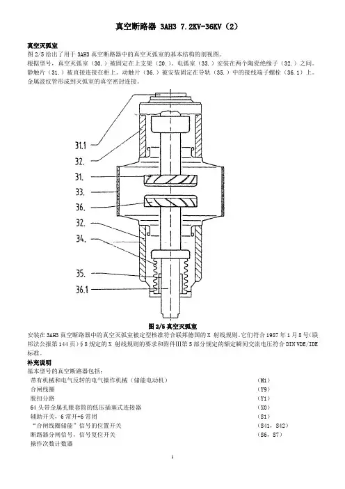
真空断路器 3AH3 7.2KV-36KV(2)真空灭弧室图2/5给出了用于3AH3真空断路器中的真空灭弧室的基本结构的剖视图。
根据型号,真空灭弧室(30.)被固定在上支架(20.)。
电弧室(33.)安装在两个陶瓷绝缘子(32.)之间。
静触片(31.)被直接连接在柜上。
动触片(36.)被安装固定在导轨(35.)中的接线端子螺栓(36.1)上。
金属波纹管形成到灭弧室的真空密封连接。
图2/5真空灭弧室安装在3AH3真空断路器中的真空灭弧室被定型核准符合联邦德国的X 射线规则。
它们符合1987年1月8号(联邦法公报第144页)§8规定的X 射线规则的要求和附件Ⅲ第5部分规定的额定瞬间交流电压符合DIN VDE/IDE 标准。
补充说明基本型号的真空断路器包括:带有机械和电气反转的电气操作机械(储能电动机)(M1)合闸线圈(Y9)脱扣分路(Y1)64头带金属孔眼套筒的低压插塞式连接器(X0)辅助开关,6常开+6常闭(S1)“合闸线圈储能”信号的位置开关(S41,S42)断路器分闸信号,信号复位开关(S6,S7)操作次数计数器防止误合闸的闭锁每个3AH3真空断路器也可以装有下面一些设备:接线板(X0)扩展的辅助开关,12常开+12常闭(S1)脱扣分路3AX1101 (Y2)电流互感器操作脱扣3AX1102 (Y4,Y5)电流互感器操作脱扣3AX1104(0.1WS)(Y6)低电压脱扣3AX1103 (Y7)手动电气合闸机械闭锁除标准的脱扣分路外,3AH3真空断路器也可以最多安装两个3AX11型脱扣分路。
在一览表HG11中声明了容许的辅助设备组合和特定的型号。
安装在配电柜或手车上安装供应的3AH3真空断路器是敞开的,可以看到“和闸弹簧脱扣”指示。
在安装3AH3真空断路器之前,先移走运输设备(制动器和定位器)。
根据提供的图纸,面向松开的相间隔板安装。
在将3AH3真空断路器安装进柜中或手车上之前,检查它的额定铭牌数据(避免混乱),比较交货单指明的额定电压与本地可供的电源电压。
s装置3VF 样本3VF Catalog分解图1 Exploded drawing描述2 Descriptions选型和订货参数Selection and ordering data线路保护型断路器Circuit-Breakers for Plant Protection3VF2 断路器,3极和4极,至100A, I cu至18kA7 3VF2 circuit-breakers, 3- and 4-pole, up to 100 A, Iup to 18kAcu3VF3 断路器,3极和4极,至160A, I cu至25kA9 3VF3 circuit-breakers, 3- and 4-pole, up to 160A, Iup to 25kAcu3VF3至3VF8断路器,3极,至2500A10 3VF3 to 3FV8 circuit-breakers, 3-pole, up to 2500A3VF3至3VF8断路器,4极,至2500A16 3VF3 to 3FV8 circuit-breakers, 4- pole, up to 2500A电动机保护型断路器Circuit-Breakers for Motor Protection3VF3、3VF5和3VF6断路器,3极,至500A14 3VF3, 3VF5 and 3VF6 circuit-breakers, 3-pole, up to 500A起动器组合用断路器Circuit-Breakers for Starter Combinations3VF3至3VF6断路器,3极,至500A14 3VF3 to 3VF6 circuit-breakers, 3-pole, up to 500A隔离型断路器Switch disconnector with short-circuit protection3VF3至3VF8断路器,3极,至2000A14 3VF3 to 3VF8 non-automatic circuit-breakers, 3-pole, up to 2000A3VF3至3VF8断路器,4极,至2000A20 3VF3 to 3VF8 non-automatic circuit-breakers, 4-pole, up to 2000A其他规格,附件和备件Further items, accessories and spare parts用于改装的附件-辅助开关和报警开关24 Accessories for retrofitting - Auxiliary and alarm switches用于改装的附件-分励脱扣器和欠压脱扣器26 Accessories for retrofitting - Shunt trips and Undervoltage releases附件-操作机构28 Accessories - Drive Mechanisms附件-连接件32 Accessories - Connections附件-锁具,罩盖36 Accessories - Locking devices, covers带DI模块的3VF3至3VF5断路器38 3VF3 to 3VF5 Circuit-breakers with DI Module技术参数40 Technical data特性曲线48 Characteristic curves线路示意图55 Circuit diagrams尺寸59 Dimensions附件-连接件Accessories - Connections相间隔板Interphase barrier主回路端子罩盖Terminal cover for main terminals 正面母排连接件Front busbar connection pieces用于3VF3的背后连接件Rear terminal for 3VF3用于3VF7的背后连接件Rear terminal for 3VF7多路进线端子Multiple feed-in terminal插入式安装底板Plug-in socket 附件-防护门框Accessories - Covers8断路器柜门开孔防护框Covering frame for door cutout附件-操作机构Accessories - Operating mechanisms9用于3VF3的电动机操作机构Motorized operating mechanism for 3VF310用于3VF4、3VF5、3VF6的旋转驱动机构Rotary drive for 3VF4, 3VF5, 3VF611柜门耦合旋转驱动机构,整套Rotary drive, complete for fitting in doorsand covers (with door coupling rotarymechanism)12DI模块DI module附件-辅助开关Accessories - Auxiliary Switches13辅助开关和报警开关,带连接线Auxiliary and alarm switchVersion with connecting leads14辅助开关和报警开关,带接线端子盒Auxiliary and alarm switchVersion with box terminals3VF3至3VF7断路器,3极和4极,至1250A 3VF3 to 3VF7 Circuit-Breakers, 3 and 4-pole, up to 1250A12标准所有3VF 断路器都符合IEC60947-1/DIN VDE0660,第100部分;IEC60947-2/DIN VDE0660,第101部分之标准。
西门子低压配电产品原装进口3VL系列塑壳断路器:型号描述单价3VL1706-1DD33-0AA0 VL160X,63A/3P热磁式脱扣,热脱器可调,分段能力40KA 900.00 3VL1708-1DD33-0AA0 VL160X,80A/3P热磁式脱扣,热脱器可调,分段能力40KA 900.00 3VL1710-1DD33-0AA0 VL160X,100A/3P热磁式脱扣,热脱器可调,分段能力40KA 900.00 3VL1712-1DD33-0AA0 VL160X,125A/3P热磁式脱扣,热脱器可调,分段能力40KA 1,200.00 3VL1716-1DD33-0AA0 VL160X,160A/3P热磁式脱扣,热脱器可调,分段能力40KA 1,450.00 3VL3720-1DC36-0AA0 VL250,200A/3P热磁式脱扣,热磁脱扣器可调,分段能力1,800.0040KA1,800.00 3VL3725-1DC36-0AA0 VL250,250A/3P热磁式脱扣,热磁脱扣器可调,分段能力40KA2,927.00 3VL4731-1DC36-0AA0 VL400,315A/3P热磁式脱扣,热磁脱扣器可调,分段能力45KA2,927.00 3VL4740-1DC36-0AA0 VL400,400A/3P热磁式脱扣,热磁脱扣器可调,分段能力45KA5,148.00 3VL5750-1DC36-0AA0 VL630,500A/3P热磁式脱扣,热磁脱扣器可调,分段能力45KA3VL5763-1DC36-0AA0 VL630,630A/3P热磁式脱扣,热磁脱扣器可调,分段能力5,148.0045KA3VL9400-2AB00 辅助开关(HS),2HS(1NO+1NC),N,左,右,131.00适用于VL160X-VL400。
系列5SX2 5SX4 5SP45SX5额定电流0.3 ... 63A 0.5 ... 50A 40 ... 125A 0.5 ... 50A额定电压(交流) 230 V~ 1P230 V~ 1P+N400V~ 2P, 3P, 3P+N,4P DC 220V 1P50/60Hz直流部分DC versionDC = 220V 1PDC = 440V2P额定短路分断能力Icn 符合标准IEC 898 6000A 10000A 10000A4500A AC10000A DC能量限制等级 3脱扣特性A,B,C,D B,C B,C,D B,C 最大额定工作电压250/440V最小额定工作电压交流或直流24V直流工作电压1P, 1P+N 至DC 60V2P 至DC 120up to DC 60V 1P, 1P+Nup to DC 120V 2P1P 至DC 220V2P 至DC 440Vup to DC 220Vup to DC 440V热脱扣的标准环境温度1)30o C工作温度范围-25o C 至+45o C (短时为+55o C),最大相对湿度95%环境气候条件根据IEC 68-2-30 标准为6 个周期储存温度-40o C to 至+75o C/ -40o C to +75o C安装位置任意进线方向上部或下部端子取决于极性接线端子防护等级为IP 2X -IPXXB,导线截面为0.75mm 2至25mm 2(5SX2, 4, 5 及5SQ35 上端子为16mm 2 )防护等级为IP2X导线截面至50mm2与5SX2 同外壳材料绝缘性能符合DIN 7708 标准,手柄可在"通"与"断"位置锁定抗震强度在每个方向为6g (g = 9.81m/s 2 ) 60m/s 2 在10..150Hz 时,根据IEC 68-2-6使用寿命在额定负载时,20 000 次/20 000易燃性符合标准DIN VDE 0304 第3 部分II b 级附件2) 辅助触头, 故障信号触头, 分励脱扣,欠压脱扣(5SP4)1 ) 当环境温度大于或小于校正(参考) 温度值时,必须根据相应的环境温度调整小型断路器的额定电流值。
DC Motors1GG7, 1GH7, 1HS7 and 1HQ7sSupplement DA 12 × July 2001DC MotorsOrder No.:German:E20002-K4012-A101-A2English:E20002-K4012-A101-A2-7600DA 12DC MotorsDA 12 Supplement1GG7, 1GH7, 1HS7 and 1HQ7July 2001Order No.:German:E86060-K5112-E101-A1English:E86060-K5112-E101-A1-7600DC DrivesPreferred Series up to 500 kW Order No.:German:E20002-K4012-A111-A2English:E20002-K4012-A111-A2-7600DA 12.1SIMOREG Chassis ConvertersOrder No.:German:E20002-K4021-A101-A3English:E20002-K4021-A101-A3-7600DA 21Spare Parts for SIMOREG Chassis Converters Order No.:German:E20002-K4021-A900-A4English:E20002-K4021-A900-A4-7600DA 21 ESIMOREG Converter Cabinet Units Order No.:German:E20002-K4022-A101-A3English:E20002-K4022-A101-A3-7600DA 22Automation and DrivesOrder No.:German:E86060-D4001-A100-B5Eng l ish: E86060-D4001-A110-B4-7600CA 01InternetVisit the Automation and Drives Group in the Internet under the following address:http://www.siemens.de/automationCatalogs of the Automation and Drives Group (A&D)Automation & Drives Catalog Interactive catalogs on CD-ROM•Components for Automation & Drives CA 01•Electrical Installation Technology ET 01Analysis SystemsGas Analysis Equipment for the Process Industry PA 10 Process Analysis, Components for Sample Preparation PA 11 SIPAN Liquid Analysis PA 20Drive SystemsVariable-Speed DrivesDC Motors DA 12 DC Drives Preferred Series up to 500 kW DA 12.1 DC Drives Preferred Series 215 kW to 1500 kW DA 12.2 SIMOREG Chassis Converters DA 21 SIMOREG Converter Cabinet Units DA 22 SIMOVERT PM Modular Converter Systems DA 45 SIEMOSYN Motors DA 48 MICROMASTER 420/440 Inverters DA 51.2 COMBIMASTER 411/MICROMASTER 411DA 51.3 SIMOVERT A Current-Source DC Link Converters DA 62 SIMOVERT MV Medium-Voltage Drives DA 63 MICROMASTER, MIDIMASTER DA 64 Low-Voltage Motors for Variable-Speed Drives DA 65.3 SIMOVERT MASTERDRIVES Vector Control DA 65.10 SIMOVERT MASTERDRIVES Motion Control DA 65.11 SIMADYN D Control System DA 99 Automation Systems for Machine Tools SIMODRIVE NC 60•AC Main Spindle Motors 1FE1, 1PH2, 1PH3, 1PH4,1PH7•AC Servomotors 1FK6, 1FT5, 1FT6•AC Linear motors 1FN1, 1FN3•Converter System SIMODRIVE 611•Converter Systems SIMODRIVE POSMO A/CD/CA/SILow-Voltage Three-Phase-Motors•Project Manual M 10•Squirrel-Cage Motors, Totally Enclosed, Fan-Cooled M 11 Drive and Control Components for Hoisting Equipment HE 1 Automation Systems for Machine ToolsSINUMERIK & SIMODRIVE NC 60 Cables, Connectors and System Components NC Z Human Machine Interface Products/SystemsSIMATIC HMIST 80SIMATIC Industrial Automation SystemsSIMATIC PCS Process Control System ST 45 SIMATIC S5/PC/505 Automation Systems ST 50 Components for Totally Integrated Automation ST 70 Supplementary Components ST 71 SIMATIC PCS 7 Process Control System ST PCS 7 Electrical Installation TechnologyProtective Switching and Fuse SystemsBuilding Management Systems with instabus EIBI 2.1Program Overview Modular Devices I 2.11 STAB Wall-Mounting Distribution Boards I 2.31 SIKUS Floor-Mounting Distribution Boards I 2.328PU Busway System I 2.36Systems Engineering Catalog Power supplies SITOP power KT 10.1 System cables SIMATIC TOP connect KT 10.2 MOBY Identification Systems KT 21 Industrial Microcomputers SICOMP KT 51 Printers and Monitors for Automation and Drives KT 61 Cabinet Packaging System for SIMATIC PCS 7KT 71Industrial Communication and Field Devices IK PILow-Voltage Controls and DistributionLow-Voltage Controlgear, Switchgear and Systems NS K Communication-Capable SIRIUS NET Controlgear,Controlgear, SIGUARD Safety Systems,Control and Signalling Devices, Switchgear,Transformers and DC Power Supplies,Main- and EMERGENCY-STOP Switches,Control Switches, Terminal BlocksSIGNUM Metallic 3SB3Products and Systemsfor Low-Voltage Power DistributionNS PS SENTRON WL NS WLTELEPERM M Process Control SystemAS 235, AS 235H and AS 235K automation systems PLT 111AS 388/TM and AS 488/TM automation systems PLT 112OS 525 operating and monitoring system PLT 122 Operating and monitoring with WinCC/TM PLT 123CS 275 bus system PLT 130Process EngineeringField Instruments for Process AutomationMeasuring Instruments for Pressure,Differential Pressure, Flow, Level and Temperature,Positioners and Liquid MetersFI 01SITRANS LR FI 01 SIWAREX Weighing Systems KT 30 Process Recorders and Accessories MP 20 SIPART, Controllers and Software MP 31Vacuum Pumps/CompressorsOil-Free Vacuum Pumps, Compressors (Blowers),Radial Blowers, Liquid PumpsPVPumpsVacuum Pumps and Compressors, System ELMO-F Cat. Sheets PF Vacuum Pumps and Compressors, System ELMO-G Cat. Sheets PGSIPOS Electric ActuatorsElectric Rotary, Linear and Part-turn Actuators MP 35 Electric Rotary Actuators for Nuclear Plants MP 35.1/.2System SolutionsApplications, Products and Services for Industry SL 01 Automation Solutions in the Plastic Industry•with SIMATIC S7SL 10•with SIMATIC S5ST 58A&D/U3/En 18.04.01Siemens AGAutomation and Drives GroupLarge Drives DivisionP.O. Box 47 43, 90025 NurembergFederal Republic of Germanyhttp://www.siemens.de/automation/ldSiemens Aktiengesellschaft Order No. E86060-K5112-E101-A1-7600sDC Drives DC Motors 1GG7, 1GH7, 1HS7 and 1HQ7 Supplement DA 12 · July 2001DC Motors 1GG7, 1GH7, 1HS7, 1HQ7Supplement DA 12 July 2001IntroductionTechnical FeaturesSelection and Ordering Data Engineering Instructionss32145Dimension DrawingsAppendixAPlease note:The technical data is provided for general information only.When mounting, operating and servicing the equipment, the Instruction Manuals and the information provided on the products themselves must be observed.We reserve the right to revise technical data, selection and ordering data (Order Nos.), accessories and the availability.All of the dimensions in this Catalog are in mm.© Siemens AG 2001Siemens Supplement DA 12 · July 20011/111/2Applications1/4Recommendations for Drive Selection 1/5Overview of Motor Types and Rated Data 1/6DiagramsSiemens Supplement DA 12 · July 2001DC Motors1IntroductionSiemens DC drives distinguish themselves as follows:•Their excellent steady-state and dynamic control response •Their wide range with high control precision•The high efficiency of the complete drive system.The modular DC motors from Siemens are well-proven in combination with driveconverters as variable-speed drives in almost all sectors of industry.This secures competitivestrengths and efficiency for our customers – within Germany and internationally.For example •In mining•In rolling mills•In the printing industry •In the textile and man-made fiber industries •For cranes•In basic industrySIMOREG drive converters.Our DC drives are the optimum solution, no matter which functions have to be fulfilled in drive, power or process engineering.DC MotorsIntroduction1Siemens Supplement DA 12 · July 20011/3Siemens Supplement DA 12 · July 2001DC Motors1IntroductionDetermine the required product profile :Supply voltage DutyDegree of protection Speed range OutputType of construction 3-ph 400, 500 or 690 V ,50/60 Hz1 quadrant/4 quadrant IP ............ n =............rpm P = ............ kWIMPage 2/2 and 3/2 onwardsInstallation conditionsAmbient temperature 40 °C Site altitude1000 mAmbient temperature > 40 °C Site altitude > 1000 m Determining the factors for output and speed changePage 4/2Determine therated armature voltageSupply configuration Duty 3 AC 50/60 Hz 400 V 1Q 3 AC 50/60 Hz 400 V 4Q 3 AC 50/60 Hz 500 V 1Q 3 AC 50/60 Hz 500 V 4Q 3 AC 50/60 Hz 690 V 1Q 3 AC 50/60 Hz 690 V4QRated armature voltage 470 V DC 420 V DC 600 V DC 520 V DC 810 V DC 720 V DCDetermine the Motor Order No.Determine the motor Order No.in accordance with the"Selection and Ordering Data"Pages 3/2 to 3/35Adapt the speed if necessary n = n Nn < n NSpeed adapted via armature control U a = U an · n / n N P = P N · n / n Nn > n NSpeed adapted via field weakening U a = constant P = constantComplete the motor Order No.Options and short codes for special featuresPages 3/39 to 3/41Select the SIMOREG drive converter and the supply componentsFor Order No. of the drive converter and the supply components,see Catalogs DA 21 and DA 22These❝Recommendations for drive selection ❞guide you step-by-step through this CatalogSiemens Supplement DA 12 · July 20011/5DC Motors1Introduction1/6Siemens Supplement DA 12 · July 2001DC Motors1Introduction$1 . . 351%1 . . 352&1 . . 353(1 . . 354)1 . . 355*1 . . 401+1 . . 402,1 . . 403-1 . . 404.1 . . 405/1 . . 45101 . . 45211 . . 45321 . . 45431 . . 455Siemens Supplement DA 12 · July 20012/122/2Standard versions 2/3Mechanical designs 2/3StandardsSiemens Supplement DA 12 · July 2001DC Motors 1GG7, 1GH7, 1HS7, 1HQ72Technical FeaturesTechnical design formotors of Series1G . 7The internally cooled,separately ventilated DC motors 1G . 7 and 1H . 7are fully laminated and compensated. They represent the optimum solution for every drive application as a result of theirmodular design regarding terminal box and separately-driven fan mounting.Standard Type Description Design All IM B3Degree of protection1GG71GH71HS71HQ7IP 23IP 23IP 54IP 54Cooling type1GH71GG71HS71HQ7IC 17IC 06IC W37 A86IC A06 A66Terminal boxPosition Alignment Cable entry All All All RightCable entry from below UndrilledCoolingSep. ventilated Sep. ventilated Closed-circuit coolingClosed-circuit cooling 1GG71GH71HS71HQ7Separately driven fan, top, NDE ExternalAir-to-water heat exchanger, top Air-to-air heat exchanger, top StatorDesign FeaturesAll All RectangularNo housing, fully laminated Duct connection 1GH7On one side, NDE right Paint finish All RAL 7016BearingsAllRoller bearing with regreasing device Vibration severity grade All NShaft end All With keyway acc. to DIN 6885, Sheet 1Balancing All Half-key balancing Field control range All 1.15 x n N Excitation Type VoltageAll All External 310 VWinding type All With compensation winding Number of polesAll4-poleFor design variants and accessories, see Options, Pages 3/39 to 3/41.Siemens Supplement DA 12 · July 2001DC Motors 1GG7, 1GH7, 1HS7, 1HQ72Technical FeaturesPractically spark-freecommutation when fed from drive converters is achieved as a result of the optimum motor design, even in the overload range. This results in extremely long brush lifetimes.Even critical applications can be handled by selecting suitable brush materials.The noise levels of the motors are determined in accordance with DIN EN 21 680 and they lie far below the values permitted according to DIN EN 60 034-9. This is achieved as a result of the mechanical design and by optimizing the magnetic circuit and the separately-driven fan.Noise levels can be provided on request.The motor bearings are provided with regreasing devices.The locating bearing is at the non drive end.The motors comply with all of the relevant standards and specifications, see adjacent table.As a result of the fact that in many countries the national regulations have beencompletely harmonized with the international IEC 60 034-1 recommendation, there are no longer any differences with respect to cooling medium temperatures, insulation classes and maximum temperature rises.Brush materials, commutation Noise levelsBearingsStandards, specifications, requirements TitleDIN/ENIECGeneral specifications for rotating, electrical machinesDIN EN 60 034-1IEC 60 034-1,IEC 60 085Terminal designations and direction of rotation for electrical machines DIN VDE 0530, Part 8IEC 60 034-8Types of construction DIN EN 60 034-7IEC 60 034-7Built-in thermal protection –IEC 60 034-11Cooling types forrotating electrical machinesDIN EN 60 034-6IEC 60 034-6Degrees of protection of rotating electrical machines DIN EN 60 034-5IEC 60034-5Vibration severity ofrotating electrical machines DIN EN 60 034-14IEC 60 034-14Cylindrical shaft ends for electrical machines DIN 748-3IEC 60 072Noise limit values ofrotating electrical machinesDIN EN 60 034-9IEC 60 034-9DC Motors 1GG7, 1GH7, 1HS7, 1HQ7 Technical Features2Siemens Supplement DA 12 · July 2001Siemens Supplement DA 12 · July 20013/13Ordering DataDC Motors 1GG7, 1GH7, 1HS73/2•Rated supply voltage 3-ph. 400 V AC Rated armature voltage 420 V DC,4 quadrant operation3/5•Rated supply voltage 3-ph. 400 V AC Rated armature voltage 470 V DC,1 quadrant operation3/8•Rated supply voltage 3-ph. 500 V AC Rated armature voltage 520 V DC,4 quadrant operation3/11•Rated supply voltage 3-ph. 500 V AC Rated armature voltage 600 V DC,1 quadrant operation3/14•Rated supply voltage 3-ph. 690 V AC Rated armature voltage 720 V DC,4 quadrant operation3/17•Rated supply voltage 3-ph. 690 V AC Rated armature voltage 810 V DC,1 quadrant operation DC Motors 1HQ73/19•Rated supply voltage 3-ph. 400 V AC Rated armature voltage 420 V DC,4 quadrant operation3/22•Rated supply voltage 3-ph. 400 V AC Rated armature voltage 470 V DC,1 quadrant operation3/25•Rated supply voltage 3-ph. 500 V AC Rated armature voltage 520 V DC,4 quadrant operation3/28•Rated supply voltage 3-ph. 500 V AC Rated armature voltage 600 V DC,1 quadrant operation3/31•Rated supply voltage 3-ph. 690 V AC Rated armature voltage 720 V DC,4 quadrant operation3/34•Rated supply voltage 3-ph. 690 V AC Rated armature voltage 810 V DC,1 quadrant operation3/36Supplementary data for selection 3/39Options3Selection and Ordering DataOutputrangeRatedoutputRated speed Order No.Rated torque Max. fieldweakening speedRated current EfficiencyPNnNMnnFmaxINh kW kW rpm Nm rpm A% 197103 1 . . 7 455-5NA . . -1VV11827041259578204138 1 . . 7 454-5NA . . -1VV11411555059580206173 1 . . 7 453-5NA . . -1VV11137069058583208210 1 . . 7 452-5NA . . -1VV1946084058084210254 1 . . 7 451-5NA . . -1VV17895102058085226119 1 . . 7 455-5NB . . -1VV11813547665581230171 1 . . 7 405-5NA . . -1VV11285051064083232158 1 . . 7 454-5NB . . -1VV11402563065083235225 1 . . 7 404-5NA . . -1VV1997068064085236275 1 . . 7 355-5NA . . -1VV1820071064086236238 1 . . 7 452-5NB . . -1VV1947095064086236196 1 . . 7 453-5NB . . -1VV11150078565085238344 1 . . 7 354-5NA . . -1VV16610103063587238288 1 . . 7 451-5NB . . -1VV17890115064087240416 1 . . 7 353-5NA . . -1VV15510125063588240335 1 . . 7 402-5NA . . -1VV16850100064087240284 1 . . 7 403-5NA . . -1VV1810085064586242492 1 . . 7 352-5NA . . -1VV14700148063589242412 1 . . 7 401-5NA . . -1VV15600124064088244580 1 . . 7 351-5NA . . -1VV14000174063590258134 1 . . 7 455-5NC . . -1VV11840053573582262196 1 . . 7 405-5NB . . -1VV11277059071585264178 1 . . 7 454-5NC . . -1VV11416571073084266322 1 . . 7 451-5NC . . -1VV17865129071088266268 1 . . 7 452-5NC . . -1VV19515107071587266256 1 . . 7 404-5NB . . -1VV1993077071587266220 1 . . 7 453-5NC . . -1VV11149588072586268392 1 . . 7 354-5NB . . -1VV16530118071088268314 1 . . 7 355-5NB . . -1VV1815094572586270320 1 . . 7 403-5NB . . -1VV1806096071588272565 1 . . 7 352-5NB . . -1VV14590169071589272475 1 . . 7 353-5NB . . -1VV15470143071589272380 1 . . 7 402-5NB . . -1VV16850114071589274660 1 . . 7 351-5NB . . -1VV13960183071590274468 1 . . 7 401-5NB . . -1VV15600140071589290151 1 . . 7 455-5ND . . -1VV11834060581583298200 1 . . 7 454-5ND . . -1VV11416080082085300224 1 . . 7 405-5NC . . -1VV11279067081086302350 1 . . 7 355-5NC . . -1VV18240105080088304438 1 . . 7 354-5NC . . -1VV16630131080089304364 1 . . 7 451-5ND . . -1VV18000131081088304302 1 . . 7 452-5ND . . -1VV19645119081588304292 1 . . 7 404-5NC . . -1VV1995088080588304248 1 . . 7 453-5ND . . -1VV11166099082587 225250300Separate ventilation usingStand., radially-mounted, sep.-driven fan G GSeparately-mounted, sep.-driven fan G HMounted air-to-water heat exchanger H SExciting voltage180 V1200 V (Order No. + Short Code L5A)9310 V4360 V7Type of constructionIM B30IM B 35 (on request)Field weakeningThe order numbers for themotors are applicable for fieldweakening speeds nFto 1.15 ·nN. For higher field weakeningspeeds, additional short codesare necessary, i.e. "C05"for nF> 1.15 ·nNto 1.7 ·nNand "C06" for nF> 1.7 ·nN.The motors can be operated atrated output PNup to the fieldweakening speed nFmax.Forhigher speeds, the output mustbe reduced.DC Motors 1GG7, 1GH7, 1HS7Siemens Supplement DA 12 · July 20013Selection and Ordering DataSiemens Supplement DA 12 · July 2001DC Motors 1GG7, 1GH7, 1HS7Output range Rated output Rated speed Order No.Rated torque Max. fieldweakening speed Rated current Efficiency P N n N M n n Fmax I N h kWkW rpm Nm rpm A %306530 1 . . 7 353-5NC . . -1VV15510154080090308735 1 . . 7 351-5NC . . -1VV14000181080091308625 1 . . 7 352-5NC . . -1VV14710167080090308432 1 . . 7 402-5NC . . -1VV16800130080589310530 1 . . 7 401-5NC . . -1VV15600160080590310364 1 . . 7 403-5NC . . -1VV18130109081589338177 1 . . 7 455-5NE . . -1VV11824072092086340252 1 . . 7 405-5ND . . -1VV11289076090588344835 1 . . 7 351-5ND . . -1VV13940182089091344500 1 . . 7 354-5ND . . -1VV16570135090090345328 1 . . 7 404-5ND . . -1VV11005098090589345232 1 . . 7 454-5NE . . -1VV11414093092588346605 1 . . 7 353-5ND . . -1VV15460151090090346400 1 . . 7 355-5ND . . -1VV18260117091589348710 1 . . 7 352-5ND . . -1VV14680164090091348484 1 . . 7 402-5ND . . -1VV16850146090091348406 1 . . 7 403-5ND . . -1VV18190122090490350590 1 . . 7 401-5ND . . -1VV15650160090091350418 1 . . 7 451-5NE . . -1VV17995132091090350348 1 . . 7 452-5NE . . -1VV19635120092090350288 1 . . 7 453-5NE . . -1VV111605108092589375675 1 . . 7 401-5NE . . -1VV15300164096092382555 1 . . 7 402-5NE . . -1VV16850146098591382464 1 . . 7 403-5NE . . -1VV17860133099091382288 1 . . 7 405-5NE . . -1VV112670860101088384375 1 . . 7 404-5NE . . -1VV197801130101090394960 1 . . 7 351-5NE . . -1VV139201760101092395462 1 . . 7 355-5NE . . -1VV181701140103090396575 1 . . 7 354-5NE . . -1VV165801310102091398695 1 . . 7 353-5NE . . -1VV154701460102092400820 1 . . 7 352-5NE . . -1VV146601590102092408215 1 . . 7 455-5NF . . -1VV118125790109088415282 1 . . 7 454-5NF . . -1VV114005935109089420505 1 . . 7 451-5NF . . -1VV179601290108092420418 1 . . 7 452-5NF . . -1VV195751180108591420348 1 . . 7 453-5NF . . -1VV11152510501095904341060 1 . . 7 351-5NF . . -1VV139001780110093440640 1 . . 7 354-5NF . . -1VV165701320113092440510 1 . . 7 355-5NF . . -1VV182401150114091440326 1 . . 7 405-5NF . . -1VV112900960115090444770 1 . . 7 353-5NF . . -1VV155101470114092445910 1 . . 7 352-5NF . . -1VV146701600114092445424 1 . . 7 404-5NF . . -1VV11003011401150914487651 . . 7 401-5NF . . -1VV156001570114092325350400Separate ventilation usingStand., radially-mounted, sep.-driven fan G G Separately-mounted, sep.-driven fan G H Mounted air-to-water heat exchangerH SExciting voltage180 V1200 V (Order No. + Short Code L5A )9310 V 4360 V7Type of constructionIM B3IM B 35 (on request)Field weakeningThe order numbers for the motors are applicable for field weakening speeds n F to 1.15 · n N . For higher field weakening speeds, additional short codes are necessary, i.e. "C05" for n F > 1.15 · n N to 1.7 · n N and "C06" for n F > 1.7 · n N .The motors can be operated at rated output P N up to the field weakening speed n Fmax. For higher speeds, the output must be reduced.3OutputrangeRatedoutputRated speed Order No.Rated torque Max. fieldweakening speedRated current EfficiencyPNnNMnnFmaxINhkW kW rpm Nm rpm A% 450625 1 . . 7 402-5NF . . -1VV169001410115092450524 1 . . 7 403-5NF . . -1VV1820012801160914881210 1 . . 7 351-5NG . . -1VV138501*********492870 1 . . 7 401-5NG . . -1VV154001*********495375 1 . . 7 405-5NG . . -1VV112610*********498485 1 . . 7 404-5NG . . -1VV198101170128092500610 1 . . 7 451-5NG . . -1VV178001040127093500600 1 . . 7 403-5NG . . -1VV179701310127092500585 1 . . 7 355-5NG . . -1VV1816011501290925051030 1 . . 7 352-5NG . . -1VV146801*********505880 1 . . 7 353-5NG . . -1VV154701*********505735 1 . . 7 354-5NG . . -1VV165601320128093505715 1 . . 7 402-5NG . . -1VV167501430128093505510 1 . . 7 452-5NG . . -1VV194751150129092505264 1 . . 7 455-5NG . . -1VV118270755133090510424 1 . . 7 453-5NG . . -1VV1115151020131092510344 1 . . 7 454-5NG . . -1VV1141609001320915151370 1 . . 7 351-5NH . . -1VV135901*********5451170 1 . . 7 352-5NH . . -1VV144501650138094550665 1 . . 7 355-5NH . . -1VV179001170140093555995 1 . . 7 353-5NH . . -1VV153401490140093555975 1 . . 7 401-5NH . . -1VV154501550140094555830 1 . . 7 354-5NH . . -1VV164101340141093555420 1 . . 7 405-5NH . . -1VV1126209401420925651600 1 . . 7 351-5NJ . . -1VV133702100142094565800 1 . . 7 402-5NH . . -1VV167501390143093565545 1 . . 7 404-5NH . . -1VV199101120144092570672 1 . . 7 403-5NH . . -1VV1810012501440936051360 1 . . 7 352-5NJ . . -1VV142501880152094605765 1 . . 7 451-5NH . . -1VV175451270153093615640 1 . . 7 452-5NH . . -1VV192051150156093625965 1 . . 7 354-5NJ . . -1VV161701540158093625775 1 . . 7 355-5NJ . . -1VV177001340158093625530 1 . . 7 453-5NH . . -1VV1112601020159593625430 1 . . 7 454-5NH . . -1VV113870895160092625330 1 . . 7 455-5NH . . -1VV1180907501620916301190 1 . . 7 401-5NJ . . -1VV1505017801580946301160 1 . . 7 353-5NJ . . -1VV151901680168094655980 1 . . 7 402-5NJ . . -1VV164001580164094670822 1 . . 7 403-5NJ . . -1VV177801430169094670520 1 . . 7 405-5NJ . . -1VV1123001090170092675670 1 . . 7 404-5NJ . . -1VV196201270171093680880 1 . . 7 451-5NJ . . -1VV173951290170594685730 1 . . 7 452-5NJ . . -1VV189351170172594685610 1 . . 7 453-5NJ . . -1VV1107251060173094695382 1 . . 7 455-5NJ . . -1VV117370770178092705496 1 . . 7 454-5NJ . . -1VV113570905179093 450550600700Separate ventilation usingStand., radially-mounted, sep.-driven fan G GSeparately-mounted, sep.-driven fan G HMounted air-to-water heat exchanger H SExciting voltage180 V1200 V (Order No. + Short Code L5A)9310 V4360 V7Type of constructionField weakeningThe order numbers for themotors are applicable for fieldweakening speeds nFto 1.15 ·nN. For higher field weakeningspeeds, additional short codesare necessary, i.e. "C05"for nF> 1.15 ·nNto 1.7 ·nNand "C06" for nF> 1.7 ·nN.The motors can be operated atrated output PNup to the fieldweakening speed nFmax.Forhigher speeds, the output mustbe reduced.3Output range Rated output Rated speed Order No.Rated torque Max. fieldweakening speed Rated current Efficiency P N n N M n n Fmax I N h kWkW rpm Nm rpm A %226119 1 . . 7 455-5NA . . -1WV11813547659080232158 1 . . 7 454-5NA . . -1WV11402563058583236197 1 . . 7 453-5NA . . -1WV11144079058584238290 1 . . 7 451-5NA . . -1WV17865116057586238240 1 . . 7 452-5NA . . -1WV1951096058585260195 1 . . 7 405-5NA . . -1WV11273059063585260136 1 . . 7 455-5NB . . -1WV11826054566082265180 1 . . 7 454-5NB . . -1WV11406072065585266256 1 . . 7 404-5NA . . -1WV1993077064087268312 1 . . 7 355-5NA . . -1WV1820094064087268326 1 . . 7 451-5NB . . -1WV17850130063588268270 1 . . 7 452-5NB . . -1WV19480108064087268224 1 . . 7 453-5NB . . -1WV11147589565086270390 1 . . 7 354-5NA . . -1WV16610117063589270380 1 . . 7 402-5NA . . -1WV16800114063589270322 1 . . 7 403-5NA . . -1WV1803097064088272555 1 . . 7 352-5NA . . -1WV14680167063590272472 1 . . 7 353-5NA . . -1WV15500142063589272466 1 . . 7 401-5NA . . -1WV15600140063589274655 1 . . 7 351-5NA . . -1WV13990184063590294153 1 . . 7 455-5NC . . -1WV11835061073584300224 1 . . 7 405-5NB . . -1WV11279067072086300202 1 . . 7 454-5NC . . -1WV11418581073086302355 1 . . 7 355-5NB . . -1WV18120107072088302292 1 . . 7 404-5NB . . -1WV1988088071588302365 1 . . 7 451-5NC . . -1WV17900134071089302302 1 . . 7 452-5NC . . -1WV19520121071588302250 1 . . 7 453-5NC . . -1WV111535100072587304445 1 . . 7 354-5NB . . -1WV16520134071589306540 1 . . 7 353-5NB . . -1WV15420155071590306430 1 . . 7 402-5NB . . -1WV16800129071090306362 1 . . 7 403-5NB . . -1WV18070109071589308635 1 . . 7 352-5NB . . -1WV14630169071590308530 1 . . 7 401-5NB . . -1WV15550159071590310745 1 . . 7 351-5NB . . -1WV13970182072091330173 1 . . 7 455-5ND . . -1WV11824069081585338254 1 . . 7 405-5NC . . -1WV11271076080588338228 1 . . 7 454-5ND . . -1WV11409591082087342496 1 . . 7 354-5NC . . -1WV16590138079590342398 1 . . 7 355-5NC . . -1WV18210120080089344330 1 . . 7 404-5NC . . -1WV1995099080589344412 1 . . 7 451-5ND . . -1WV17995131081090344342 1 . . 7 452-5ND . . -1WV19635119081589345600 1 . . 7 353-5NC . . -1WV15490154080091345282 1 . . 7 453-5ND . . -1WV111685106082588346705 1 . . 7 352-5NC . . -1WV14690168080091348830 1 . . 7 351-5NC . . -1WV140001820800923484881 . . 7 402-5NC . . -1WV16800146080590250300Separate ventilation usingStand., radially-mounted, sep.-driven fan G G Separately-mounted, sep.-driven fan G H Mounted air-to-water heat exchangerH SExciting voltage180 V1200 V (Order No. + Short Code L5A )9310 V 4360 V7Type of constructionIM B3Field weakeningThe order numbers for the motors are applicable for field weakening speeds n F to 1.15 · n N . For higher field weakening speeds, additional short codes are necessary, i.e. "C05" for n F > 1.15 · n N to 1.7 · n N and "C06" for n F > 1.7 · n N .The motors can be operated at rated output P N up to the field weakening speed n Fmax. For higher speeds, the output must be reduced.3OutputrangeRatedoutputRated speed Order No.Rated torque Max. fieldweakening speedRated current EfficiencyPNnNMnnFmaxINhkW kW rpm Nm rpm A% 350600 1 . . 7 401-5NC . . -1WV15550160080591350412 1 . . 7 403-5NC . . -1WV18130124081590384202 1 . . 7 455-5NE . . -1WV11815080592087385370 1 . . 7 404-5ND . . -1WV19950111089590385285 1 . . 7 405-5ND . . -1WV11290086090589388940 1 . . 7 351-5ND . . -1WV13940181089092388565 1 . . 7 354-5ND . . -1WV16560136090091390680 1 . . 7 353-5ND . . -1WV15480151090091390264 1 . . 7 454-5NE . . -1WV11411095092089392805 1 . . 7 352-5ND . . -1WV14650164090092392452 1 . . 7 355-5ND . . -1WV18280117091590392545 1 . . 7 402-5ND . . -1WV16850145090091392460 1 . . 7 403-5ND . . -1WV18160133090291394665 1 . . 7 401-5ND . . -1WV15650160090092394472 1 . . 7 451-5NE . . -1WV17955132091091395392 1 . . 7 452-5NE . . -1WV19600120091591396326 1 . . 7 453-5NE . . -1WV111600108092590422760 1 . . 7 401-5NE . . -1WV15300164096092430625 1 . . 7 402-5NE . . -1WV16850146098592432524 1 . . 7 403-5NE . . -1WV17890132099091432424 1 . . 7 404-5NE . . -1WV197401170100091432326 1 . . 7 405-5NE . . -1WV112660*********4421080 1 . . 7 351-5NE . . -1WV139101*********446650 1 . . 7 354-5NE . . -1WV165501310102092446520 1 . . 7 355-5NE . . -1WV181901140103091448785 1 . . 7 353-5NE . . -1WV154501*********450920 1 . . 7 352-5NE . . -1WV146701*********464244 1 . . 7 455-5NF . . -1WV118160*********470318 1 . . 7 454-5NF . . -1WV114025*********472570 1 . . 7 451-5NF . . -1WV179351290108092474392 1 . . 7 453-5NF . . -1WV1115201050109591475472 1 . . 7 452-5NF . . -1WV1961011801090924861200 1 . . 7 351-5NF . . -1WV138701*********495575 1 . . 7 355-5NF . . -1WV182201140115092496720 1 . . 7 354-5NF . . -1WV165801320113092498870 1 . . 7 353-5NF . . -1WV154601*********498368 1 . . 7 405-5NF . . -1WV112920*********5001020 1 . . 7 352-5NF . . -1WV146801*********500478 1 . . 7 404-5NF . . -1WV199901150115091505860 1 . . 7 401-5NF . . -1WV156001*********505705 1 . . 7 402-5NF . . -1WV168501410115092510592 1 . . 7 403-5NF . . -1WV1824012701160925401360 1 . . 7 351-5NG . . -1WV137901*********545980 1 . . 7 401-5NG . . -1WV153001********* 350400500Separate ventilation usingStand., radially-mounted, sep.-driven fan G GSeparately mounted, sep.-driven fan G HMounted air-to-water heat exchanger H SExciting voltage180 V1200 V (Order No. + Short Code L5A)9310 V4360 V7Type of constructionField weakeningThe order numbers for themotors are applicable for fieldweakening speeds nFto 1.15 ·nN. For higher field weakeningspeeds, additional short codesare necessary, i.e. "C05"for nF> 1.15 ·nNto 1.7 ·nNand "C06" for nF> 1.7 ·nN.The motors can be operated atrated output PNup to the fieldweakening speed nFmax.Forhigher speeds, the output mustbe reduced.。
西门子电机样本6ES5,6ES7,6AV,6XV,6EP,6GK,6AG,6RA,6SE,6SL,6SY,6RY,6SN,6FC ,6FX,1PP,2CF,1FT,1FK,1PH,C98043,6DD,6DR,7MH,7ML。
C98043-A1603-L4接电缆-ALLEN BRADLEY SLC500/03,04 - PC (RS232/9 针接头)6XV1801-5DE30 M12-180/M12-180 电源连接电缆,用于ET200 电源,预装配电缆,带M12 连接器和M12 A 编码插座连接器,5 针,0.3m6XV1801-5DE50 M12-180/M12-180 电源连接电缆,用于ET200 电源,预装配电缆,带M12 连接器和M12 A 编码插座连接器,5 针,0.5m6XV1801-5DH10 M12-180/M12-180 电源连接电缆,用于ET200 电源,预装配电缆,带M12 连接器和M12 A 编码插座连接器,5 针,1.0m6XV1801-5DH15 M12-180/M12-180 电源连接电缆,用于ET200 电源,预装配电缆,带M12 连接器和M12 A 编码插座连接器,5 针,1.5m6XV1801-5DH20 M12-180/M12-180 电源连接电缆,用于ET200 电源,预装配电缆,带M12 连接器和M12 A 编码插座连接器,5 针,2.0m6XV1801-5DH30 M12-180/M12-180 电源连接电缆,用于ET200 电源,预装配电缆,带M12 连接器和M12 A 编码插座连接器,5 针,3.0m6XV1801-5DH50 M12-180/M12-180 电源连接电缆,用于ET200 电源,预装配电缆,带M12 连接器和M12 A 编码插座连接器,5 针,5.0m6XV1801-5DN10 M12-180/M12-180 电源连接电缆,用于ET200 电源,预装配电缆,带M12 连接器和M12 A 编码插座连接器,5 针,10.0m6XV1801-5DN15 M12-180/M12-180 电源连接电缆,用于ET200 电源,预装配电缆,带M12 连接器和M12 A 编码插座连接器,5 针,15.0m6XV1812-8A SIMATIC NET 电源电缆, 2 线制电源电缆, LITZ 导线, 2 x 0.75 平方毫米, 拖缆,最大长度: 2000m, 最小订购长度: 20m, 按米销售6XV1820-5AH10 SIMATIC NET, 光纤标准电缆,C98043-A1603-L46XV1821-0BN15 SIMATIC NET, PROFIBUS 塑料光纤,标准光缆, 带有4 个BFOC 连接器,L = 15m6XV1821-0BN20 SIMATIC NET, PROFIBUS 塑料光纤,标准光缆, 带有4 个BFOC 连接器,L = 20m6XV1821-0BN25 SIMATIC NET, PROFIBUS 塑料光纤,标准光缆, 带有4 个BFOC 连接器,L = 25m6XV1821-0BN30 SIMATIC NET, PROFIBUS 塑料光纤,标准光缆, 带有4 个BFOC 连接器,L = 30m6XV1821-0BN50 SIMATIC NET, PROFIBUS 塑料光纤,标准光缆, 带有4 个BFOC 连接器,L = 50m6XV1821-0BN65 SIMATIC NET, PROFIBUS 塑料光纤,标准光缆, 带有4 个BFOC 连接器,L = 65m6XV1821-0BN80 SIMATIC NET, PROFIBUS 塑料光纤,标准光缆, 带有4 个BFOC 连接器,L = 80m6XV1821-1BN75 SIMATIC NET, PROFIBUS PCF 光纤,带有4 个BFOC 连接器,L = 75m6XV1821-1BT10 SIMATIC NET, PROFIBUS PCF 光纤,带有4 个BFOC 连接器,L = 100m6XV1821-1BT15 SIMATIC NET, PROFIBUS PCF 光纤,带有4 个BFOC 连接器,L = 150m6XV1821-1BT20 SIMATIC NET, PROFIBUS PCF 光纤,带有4 个BFOC 连接器,L = 200m6XV1821-1BT25 SIMATIC NET, PROFIBUS PCF 光纤,带有4 个BFOC 连接器,L = 250m6XV1821-1BT30 SIMATIC NET, PROFIBUS PCF 光纤,带有4 个BFOC 连接器,L = 300mC98043-A1603-L4户内安装的玻璃光纤电缆, 按米销售, 最大长度: 2000m, 最小订购长度: 20 m6XV1820-7BH05 SIMATIC NET, 户内用纤维光缆, 无卤素, 抗踩踏, 阻燃, 用于户内安装的玻璃光纤电缆, 预装有4 个BFOC 接头, 长度0.5m6XV1820-7BH10 SIMATIC NET, 户内用纤维光缆, 无卤素, 抗踩踏, 阻燃, 用于户内安装的玻璃光纤电缆, 预装有4 个BFOC 接头, L = 1m6XV1820-7BH20 SIMATIC NET, 户内用纤维光缆, 无卤素, 抗踩踏, 阻燃, 用于户内安装的玻璃光纤电缆, 预装有4 个BFOC 接头, L = 2m6XV1820-7BH30 SIMATIC NET, 户内用纤维光缆, 无卤素, 抗踩踏, 阻燃, 用于户内安装的玻璃光纤电缆, 预装有4 个BFOC 接头, L = 3m6XV1820-7BH50 SIMATIC NET, 户内用纤维光缆, 无卤素, 抗踩踏, 阻燃, 用于户内安装的玻璃光纤电缆, 预装有4 个BFOC 接头, L = 5m6XV1820-7BN10 SIMATIC NET, 户内用纤维光缆, 无卤素, 抗踩踏, 阻燃, 用于户内安装的玻璃光纤电缆, 预装有4 个BFOC 接头, L = 10m6XV1820-7BN15 SIMATIC NET, 户内用纤维光缆, 无卤素, 抗踩踏, 阻燃, 用于户内安装的玻璃光纤电缆, 预装有4 个BFOC 接头, L = 15 m6XV1820-7BN20 SIMATIC NET, 户内用纤维光缆, 无卤素, 抗踩踏, 阻燃, 用于户内安装的玻璃光纤电缆, 预装有4 个BFOC 接头, L = 20 m6XV1820-7BN25 SIMATIC NET, 户内用纤维光缆, 无卤素, 抗踩踏, 阻燃, 用于户内安装的玻璃光纤电缆, 预装有4 个BFOC 接头, L = 25 m6XV1820-7BN50 SIMATIC NET, 户内用纤维光缆, 无卤素, 抗踩踏, 阻燃, 用于户内安装的玻璃光纤电缆, 预装有4 个BFOC 接头, L = 50 m6XV1820-7BN75 SIMATIC NET, 户内用纤维光缆, 无卤素, 抗踩踏, 阻燃, 用于户内安装的玻璃光纤电缆, 预装有4 个BFOC 接头, L = 75 m6XV1820-7BT10 SIMATIC NET, 户内用纤维光缆, 无卤素, 抗踩踏, 阻燃, 用于户内安装的玻璃光纤电缆, 预装有4 个BFOC 接头, L = 100 m6XV1821-0AH10 SIMATIC NET, PROFIBUS 塑C98043-A1603-L4。
Control Circuit Protection Gener a l D a t a
Control Circuit Protection 5SJ Branch Circuit Protection
Control Circuit Protection 5SJ Branch Circuit Protection
Control Circuit Protection General Data
and are mounted to the right of them.
Control Circuit Protection
General Data
5SJ4...-.HG405SJ4...-.HG42
5ST3 663-0HG 5ST3 663-1HG 5ST3 663-2HG 5ST3 664-0HG 5ST3 664-1HG 5ST3 664-2HG 5ST3 665-0HG 5ST3 665-1HG 5ST3 665-2HG
5ST3 666-0HG 5SJ4...-.HG41
5ST3 666-1HG
5ST3 666-2HG
Control Circuit Protection
5SY4 Supplementary Protection
Control Circuit Protection 5SY4 Supplementary Protection
Control Circuit Protection Supplementary Protection, AC/DC Product Range
Control Circuit Protection Supplementary Protection
5
Control Circuit Protection Supplementary Protection Accessories
Control Circuit Protection Supplementary Protection, General Data
Control Circuit Protection
General Data
•Meets a wide variety of fuse sizes •Multi-pole configurations
•Standard 35 mm (DIN) rail mounting •
Housing material meets UL-94-V0, self-extinguishing
•Meets UL 512 and CSA C22.2, No. 39 certifications
•CE Mark
•No tools required for insertion or removal of fuses •Finger safe design
•With or without Blown Fuse Indicator •Draw design includes spare fuse holder
Depending on the cylindrical* fuse size selected 3NW7 fuse holders are available in 1, 1 + N, 2, 3, 3 + N and 4 pole configu-rations. Fuse sizes include 13/32" x 1-1/2"(Class CC and Midget), 8 mm x 32 mm, 10 mm x 38 mm, 14 mm x 51 mm and 22 x 58 mm.
Class CC fuse holders are UL Listed for branch circuit protection according to UL 512 and CSA C22.2, No. 39. They incorporate a rejection feature that only allows Class CC fuses to be used.Midget, 8 mm x 32 mm, 10 mm x 38 mm,14 mm x 51 mm, and 22 x 58 mm fuse holders are UL Recognized (refer to Technical Data for specific fuse holder certifications) as supplementary protectors according to UL 512 and CSA C22.2, No. 39. Supplementary protectors are designed to provide additional protection along with branch circuit protection
devices.
All fuse holders are equipped with either a fuse handle or draw mechanism for easy insertion and removal of cylindrical type fuses. During insertion and removal the fuses are isolated from the power/control circuit. Their compact size requires less space than typical open-type fuse holders and they mount directly onto standard 35 mm mounting rails.
Fuse holders for 8 mm x 32 mm, 10 mm x 38 mm fuses in the 1 + N draw design occupy the same mounting space as 1pole designs. This unique design saves space when compared to the typical han-dle type fuse holder which requires two poles.
1) Same Mechanical Design - Other Pole Types Not Shown
2) LED is “ON” when fuse is blown (open)3) UL 508 busbar available; 5ST3701-0HG, 5ST3705-0HG, 5ST3710-0HG.
See page 16/19.
E
Control Circuit Protection General Data
Control Circuit Protection
Supplementary Protection
3NC1038 open fuse holders have been certified in accordance with UL512 and can be used with 13/32" x 1/1-2" (10 x 38 mm) fuses up to 600 V AC, 30 Amperes maximum.
•Type M Supplementary Fuse Holder for use with 13/32" x 1-1/2" (10 x 38 mm) Fuses
•Typical Supplementary Fuses: Bussmann KTK, FNQ, FNM, BAF and BAN. Includes MIDGET Class Fuses
•Ampere Rating: 32A
•Voltage Rating: 600 V
•Withstand Rating: 10,000 RMS Symmetrical (or interrupting rating of the fuse used, whichever is lower)
•Wire Range: 18 to 4 AWG
• UL Recognized, UL 512, Fuse Holder
•UL Flammability: 94VO
•Holder Material:Thermoplastic
•Surface Mounted。