【最新】太阳能充电宝说明书范文-推荐word版 (7页)
- 格式:docx
- 大小:18.57 KB
- 文档页数:7
太阳能充电器说明书一、产品结构:内置高容量储蓄锂电池(18650),IC智能过流过载保护,单晶硅光伏电池板2W,220V,50HZ单相交流,LED镇流驱动显示,整机由交流,USP直流,单晶硅光伏充电等多功能储藏电荷。
部份产品带LED灯手电照明,收音机功能,铝合金外壳。
二、产品特点:容电量大,华贵大方,携带方便,时尚高雅,节能环保,充电1小时搞定,特别适合出差,旅游,长途乘车,找工作,野外施工,商务会议等手机充电。
只要接入手机就能使用,并适用于数码照相机,DV,PDA,MP3,MP4,GPS,平板电脑及部份笔记本电脑电源充电,产品用途广泛。
三、技术参数:输入交流AC220V,50HZ,储存电能充电时间:1~3小时,直流DC3V接USB电脑接口,储存电能充电时间:2~5小时,光伏储存电能:6V,2W,60一150MAX,转换效率25%以上,储存电能时间:6~8小时,指示灯显示100%,表示储存电能充满,输出电压:4.5V,5V,6V,9V,12V等多个供电选择,充满电后自动恒压3.7~4.2V。
不会损坏手机,电流:2600MAH一5000MAH,最大10000MA。
手机充电时间1小时搞定。
四、使用方法:1、使用本产品前要交流充电,以提高内存电池的使用效率。
2、接口IN为输入储存电能充电,接口OUT为输出给手机充电或其它产品充电。
3、手机充电前要选好与手机相符合的电压档,一般选4.5V,视手机能量而定。
4、看手机屏信号是否处于充电状态。
五、注意事项:1、光伏充电时,要光伏正面向光直射,确保效果。
2、注意防潮,防高温,防划伤光伏表面。
3、请用厂家提供的专用数据充电适配线和转接头。
4、不可用短路或损坏的电池接入充电,否则会损坏充电宝。
5.没有显示充电,可能内存电能不足或接触不良。
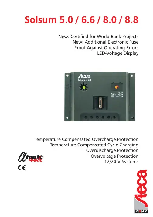
New:Certified for World Bank ProjectsNew:Additional Electronic Fuse Proof Against Operating ErrorsLED-Voltage DisplayTemperature Compensated Overcharge ProtectionTemperature Compensated Cycle ChargingOverdischarge Protection Overvoltage Protection12/24V SystemsSolsum 5.0/6.6/8.0/8.8T e c h n i c a l a l t e r a t i o n s c a n b e m a d e w i t h o u t p r i o r n o t i c e .I l l u s t r a t i o n s a n d d e s c r i b t i o n s d o n o t c l a i m t o b e c o m p l e t e .-S 03.674-01.02Our newest,and fourth,generation of solar charge controllers sets new standards in solar technology.For the first time a solar charge controller is offered in the market which is equipped with an integrated circuit (ASIC )specially designedfor solar charging.This integrated circuit,called Atonic ,provides a charge controller with new functions.Atonic is more than protective device for your battery,and contains the most recent and innovative technolgy.Overcharge protection is provided by a pulse-with-modulated shunt controller which guarantees quick and gentle charging of the battery (characteristic IV curve ).Wear-resistant MOSFET transistors are used for the overdischarge protection in this charge controllers,whereby a maintenance-free operation with an extremely long product life is ensured.Absolutely new in this price class is a cycle charging,boost charging and a temperature compensation which are regularly integrated in these charge controllers.An LED colour display gives information about voltage of the accumulator.Safety Features:Charging Functions:Overvoltage protection by integrated varistor Wrong polarity protection at Battery and ModuleProof against operation errors Built-in fuseElectronically short circuit protected Voltage-display by changing colour Low voltage disconnection LVD Shunt regulator -fast and gentle charging Time-delayed overdischarge protectionTemperature compensation by built-in sensor Automatic voltage adaption Cycle charging Boost charging Schottky diode MOSFET switchLED-display of charging functionred 11,8V yellow to red-yellow 12,3V green 12,8V Solsum Charge Controllers set new Standards in this Price and Power Class!T echnical Data:For a detailed description please see the AtonIC data sheet.AtonIC is a registered trademark of Steca GmbH.*1)Athon was an Egyptian god called:"Master of the Sun"®Solarix,AtonIC,the LED colour display and the hybrid control system,G9317097.1and G 9317338.5are both registered under German patent and Trade Name Office.。
本文部分内容来自网络整理,本司不为其真实性负责,如有异议或侵权请及时联系,本司将立即删除!== 本文为word格式,下载后可方便编辑和修改! ==太阳能充电宝说明书范文篇一:太阳能充电宝实验报告电子实训(设计)课题姓名学号专业 11电子信息工程指导教师李老师第一章绪论1.1 设计目的随着通信技术的迅猛发展,化石能源被日益消耗甚至即将面临枯竭,全球能源问题日益严重。
另外人们的环境保护意识越来越强烈,寻找各种清洁能的源来代替化石能源变得尤为重要。
太阳能作为一种可再生资源有取之不尽用之不竭的有点,并且清洁安全。
因此太阳能有着广泛的应用前景。
所以移动电源顺应时代的发展,本文主要介绍自制的简易移动电源,主要利用tp4056充电控制芯片来控制整个电路的运作,电路中还有多种贴片电阻,贴片电容,贴片二极管MDDSS14,和电感,接上5V电源后,会发现LED灯会亮,接不同的电压,灯亮的个数会不一样。
通过这次实训,有了很大的收获。
1.2 设计思路和分析相信大家多少都接触过太阳能吧,我们接触最多大概有三种:单晶硅,多晶硅,非晶硅。
单晶硅的效率最高,非晶硅的弱光响应最好。
选取的非晶硅尺寸为50*50 电压4.5伏电流30毫安以及电池芯片管理TP4056总电路原理图第二章硬件电路设计电源稳压器:电源稳压器选用的是TP4056芯片,TP4056充电控制芯片是一款完整的单节锂离子电池采用恒定电流/恒定电压线性充电器。
其底部带有散热片的 SOP8 封装与较少的外部元件数目使得 TP4056充电控制芯片成为便携式应用的理想选择。
TP4056充电控制芯片可以适合 USB 电源和适配器电源工作。
由于采用了内部 PMOSFET 架构,加上防倒充电路,所以不需要外部隔离二极管。
热反馈可对充电电流进行自动调节,以便在大功率操作或高环境温度条件下对芯片温度加以限制。
充电电压固定于 4.2V,而充电电流可通过一个电阻器进行外部设置。
当充电电流在达到最终浮充电压之后降至设定值1/10 时,TP4056充电控制芯片将自动终止充电循环。
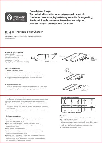
Usage instruction1. Charging under direct sunlightOpen the solar charger and keep solar panels upright facing direct sunlight.Note:You can use the holder to adjust the height of the solar charger for the best angle.A red light will indicate that the device is charging. The light will automaticallyturn off when the device has been fully charged.2. harging using the USB cableConnect the solar charger with the supplied USB cable and insert it into a power supply.There are 4 LED indicators (refer to the table below) that will flash in blue to indicate the remaining battery levels. When fully charged, 4 blue LEDs will light steadily.Capacity: 8000mAhI n p u t : USB/Solar panel DC 5V/2.0AOutput: Smart ID DC 5V/2.4AS i z e : 9.52" x 6.89" x 0.75" (175x242x19mm)Weight: approx. 1.43lb (650g)Operating Temperature: 32 ℉-140 ℉ (0℃-60℃)Product SpecificationNote:You can press the power button to check the remaining battery levels when not connected with a USB cable.If the device will not be used for an extended period of time, store it in a clean, dry place and charge it every 3-6 months.3. Charging an external portable digital deviceUpon connecting the solar charger with your electronic equipment (through the USB cable), the LEDs will flash and the solar charger will automatically start charging your device. When fully charged, the solar charger will automatically turn off and enter into sleep mode.Features Please read this user manual carefully before use and keep for future reference.Do not place the device on a soft surface, such as a carpet or couch.Do not throw the solar charger into fire.Do not crush, impale, disassemble or attempt to repair the solar charger.Ensure there are no flammable substances, explosive gases, flames, smoke orspark near the solar charger.Do not scratch or bend the solar panels.Keep the surface of solar panels clean from dust. Clean it with a soft cloth.Avoid solar panel contact with water or any other liquid (corrosive, acid or alkali).Operate it under a temperature of 0℃ ~ 40℃.Adult supervision is recommended at all times when a child is operating the device.Charge the device with the supplied adapter.When battery levels are low, as indicated by a single flashing indicator or no flashing, stop using the solar charger and charge it immediately.Safety precautionRefuel your devices’ batteries on your outdoor adventures and short trips.Up to 25% high conversion eciency.Professional built-in circuit to prevent over-discharge, over-charge, over-current and heat reduction when charging the built-in battery via USB cable or sunlight.Sturdy and durable, perfect for perfect for traveling or outdoor es with a height-adjustable holder to capture maximum sunlight.4 LED indicators that indicate battery levels.IC-SB11Y Portable Solar Charger(8000mAh)。
太阳能充电器使用说明书本产品是一款多功能太阳能应急充电器,内置1200mAh高容量可充电锂电池,可随时随地对您的手机、数码相机、PDA、MP3、MP4等数码产品进行充电。
造型华贵大方,小巧玲珑,携带方便,时尚高雅。
使用方法1、使用之前请给您的太阳能充电器充电,有三种方法可以选择:a、将充电器放置于太阳光直射处,太阳能将转化为电能给充电器内置可充电电池充电。
b、将充电器USB线连接电脑,此时充电器指示灯会闪光,表示正在充电,当充电满后,此灯将会熄灭。
C、用交流适配器充电,充电时指示灯会闪光,当充电满后此灯将会熄灭(因为设计有自动断电保护)2、将转换接头连接到延长线,再将延长线的另一头连接到充电器,或直接将转接头连接到充电器。
3、将转换接头连接到您的手机或其它数码产品。
4、从您的手机或其它数码产品上将可看到正在充电,充电的同时您也可以用手机通话。
5、太阳能充电指示。
将开关拨到‘NO’,太阳能板在接受阳光照射时,太阳能充电指示呈绿色。
产品特点:1、特别适用于应急场合。
当您在野外作业或旅游,或者遇到停电时,太阳能充电器将会帮您的大忙,使您的手机随时随地保持工作状态,让您不间断的与您的朋友和家人保持联系。
2、使用方便无论何时何地,您都可以极为方便的给您的手机或其它数码产品充电。
3、高效率充电给您的手机充电60分钟,可以获得100-150分钟通话时间4、环保、节约能源使用绿色能源太阳能,可为环保作出您的贡献。
5、外形时尚,携带方便造型简洁华贵,超薄不锈钢外壳设计,小巧玲珑,携带方便。
6、使用安全带有充电过充保护,有效延长您的手机电池的使用寿命,使用安全。
产品规格1、使用高转换效单晶硅或多晶硅片,太阳能转换效率高达15%以上。
2、太阳能电池板规格:5.5V/80mA。
3、充电时内置高容量可充电锂电池:1200 mAh。
4、输出电压:5.5V。
5、输出电流:1000mA。
6、充电器给手机充电时间:约60分钟(不同品牌和型号的手机有少许差别)。
太阳能充电宝操作规程1. 前言太阳能充电宝(以下简称充电宝)是一种采用太阳能充电的便携式电池装置,可为各种电子设备提供充电功能。
为了保证您在使用充电宝时的安全和效果,特制定本操作规程。
2. 充电宝的基本构造和工作原理充电宝主要由太阳能电池板、锂电池、充电电路、输出接口和控制板组成。
太阳能电池板将太阳能光线转换为电能并储存于锂电池中,通过充电电路将储存的电能输出给需要充电的设备。
3. 充电宝的操作步骤3.1. 充电3.1.1. 确保充电宝电量充足,如果电量低于20%,请及时进行充电。
3.1.2. 将充电宝背面的太阳能电池板置于阳光下,确保透明部分能够受到充足的阳光照射。
3.1.3. 充电宝显示屏将显示当前充电情况,直到电量充满为止。
请不要将充电宝背面遮挡物影响光线的正常吸收。
3.2. 充电设备3.2.1. 在使用充电宝充电设备之前,请先确保充电宝电量充足。
3.2.2. 插入充电宝输出接口与设备需充电的接口匹配,并确保连接牢固。
3.2.3. 开启充电宝电源开关,开始为设备充电。
3.2.4. 充电完成后,及时拔出充电宝与设备的连接。
4. 充电宝的注意事项4.1. 充电宝不宜长时间暴露在高温或低温环境中,避免引发电池过热或过冷情况。
4.2. 充电宝不可与易燃物品或湿润环境接触,防止发生火灾或电池损坏。
4.3. 请勿将充电宝进行拆解或修理,以免引发电击或其他安全事故。
4.4. 充电宝不可直接投入水中,避免电子元件受潮导致电池损坏或发生电击事故。
5. 充电宝的维护与保养5.1. 定期充电:为了保持充电宝的正常工作状态,请至少每三个月进行一次充电,确保电池长期保持良好状态。
5.2. 温度适宜:存放充电宝时,请选择干燥、通风、温度适宜的环境,避免过高或过低的温度对电池产生负面影响。
5.3. 清洁保养:请使用软布轻轻擦拭充电宝表面,定期清除灰尘或污渍。
5.4. 防干燥:长时间不使用时,请确保充电宝存放在干燥的环境中,避免电池因长时间未使用而失去活性。
篇一充电宝综合说明书概述超威便携式移动电源是一种集供电和充电功能于一体的便携式充电装置的电能存储器,由高能量集合物锂离子电芯作为储电载体。
具有大容量、多用途、体积小、寿命长和安全可靠等特点。
使用说明适用于mn0510mh 、mn0510ma/8g、mn0505mb 、mn0505md 、mn0505mf 、 mn0502mc型号照明功能长按按键3s 以上,led 照明开启,再轻按按钮则关闭led 照明(mn0502mc 除外);对数码产品充电将充电线接入usb口,轻按按键,即可给dc5v 输入的电子产品充电,充电过程中电量指示灯长量,提示剩余电量。
(mn0502mc 无需按按键,充电过程中无电量显示);对移动电源充电选择适配器(输出直流电压5v )或电脑usb 口,将充电头插入移动电源充电口,即可给移动电源进行充电;电量查询短按按键,即可查询移动电源剩余电量(mn0502mc 不可查询剩余电量,在缺电的情况下会亮红灯,表示需要充电);休眠状态在无充、放电(既待机状态),无照明时,5分钟后自动进入休眠状态;适用于mn1910me型号对移动电源充电请用输出直流电压15~19v,电流≧2a 的适配器对移动电源进行充电,充电时lcd 显示充电状态(电量格成流水状跳动)和输出口输出电压。
当适配器电压不符合要求时,电量格整体闪动。
开机和关机在关机状态下,短按按键开机,开机显示当前电池电量、输出口输出电压、usb 符号。
关机输出口未接入负载并不在输出锁定状态时,可以短按按键关机;输出口未接入负载并不在输出锁定状态时,电源在无负载时10分钟后自动关机;输出口接入负载后,须长按按键关机;显示锁定符号时电源不会自动关闭,将保持长期开机状态。
对数码产品进行充电对数码产品充电时,usb 口可以对5v 的数码产品如手机,ipad 等进行充电,usb 口输出不随手动调整电压而变动,恒定输出5v ;dc输出口输出电压可以在5v/4v/9v/12v/16v/19v之间循环调整,在未接入负载时,长按按键即可调整电压,持续长按,电压连续调整。

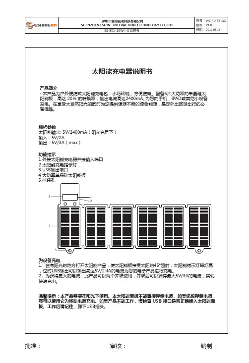
太阳能充电器说明书规格参数太阳能输出: 5V/2400mA(阳光充足下)输入:5V/2A 输出:5V/3A(max)功能指示1 外接太阳能充电器并接输入端口2 太阳能充电指示灯3 USB输出端口4 大功率单晶硅太阳能板5 挂绳孔批准:审核:编制:产品简介· 本产品为户外便携式太阳能充电包,小巧玲珑,方便携带。
配备6片大功率的单晶硅太阳能板,高达 20% 的转换率,输出电流高达2400mA, 为您的手机、IPAD或其他小设备充电。
在享受大自然阳光的同时为您提供源源不断的绿色能源,是您外出旅游出行的必备佳品。
为设备充电1、在有阳光的地方打开太阳能产品,使太阳能板接受太阳的45°照射,太阳能指示灯绿灯亮,这时USB输出可以输出高达5V/2.4A的电流为您的电子产品进行充电。
2、为获得更大的电流,此产品可以两个并联使用,并联后可以获得最大5V/3A的电流,实现快速充电。
温馨提示:本产品需要在阳光下使用。
本太阳能面板不能直接存储电源,如果您想存储电源,您可以使用它为移动电源充电。
如果产品不能工作,请检查 USB 接口是否正确插入太阳能面板。
工作后请记住,卸下USB插头。
12345User manualSpecification parameterSolar charging :5V/2400mA(In full sunshine)Input :5V/2AOutput :5V/3A (max )批准:审核:编制:·Product introduction·The product is an outdoor portable solar chager, small and exquisite, easy to carry. Equipped with 6 high-power mono-crystalline silicon solar panels, high transmit efficiency 20%, up to 2400mA max charging current, It can charge mobile phone ,IPAD or other small mobile devices. It willprovide you with green energy while enjoying the natural sunshine ,which will be your travelnecessity.Charger the device1、Open the solar energy product in a place with sunlight, so that the solar panel receives 45° illumina-tion from the sun, the solar indicator is green, and the USB output can up to 5V/2.4A to charge your electronic products.2、For more current , It can be used in parallel for two or three products. After parallel ,the maximum current output : 5V/3A can be obtained to achieve fast charging.Tips: This product needs to be used in the sun. This solar panel cannot store power directly. If you want to store power, you can use it to charge mobile power. If the product does not work, check that the USB connector is properly inserted into the solar panel. Remember to remove the USB plug after work.Function indication1.External solar charger connected to the input port2.Solar charging indicatorB output port4.High power mono-crystalline silicone solar panelnyard hole12345。
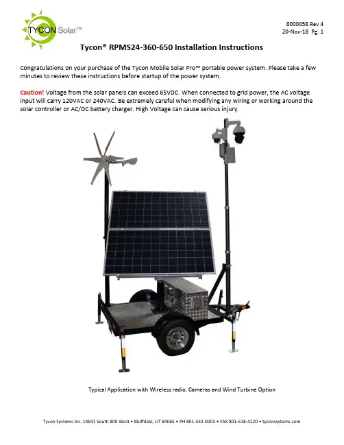
Tycon® RPMS24-360-650 Installation Instructions Congratulations on your purchase of the Tycon Mobile Solar Pro™ portable power system. Please take a few minutes to review these instructions before startup of the power system.Caution! Voltage from the solar panels can exceed 65VDC. When connected to grid power, the AC voltage input will carry 120VAC or 240VAC. Be extremely careful when modifying any wiring or working around the solar controller or AC/DC battery charger. High Voltage can cause serious injury.Typical Application with Wireless radio, Cameras and Wind Turbine OptionNotes:1.The basic trailer systemcomes complete with abattery control box outfittedwith eight 6V 180Ahbatteries, a 40A MPPT solarcontroller with 20A loadoutput, a 900W AC/DCBattery Charger, a 24VDC to56VDC 5A converter, aTPDIN-Monitor-WEB2 remotepower monitor, a 18’pneumatic extension mastwith 12V air-pump, a junctionbox at top of pole with a 5Port Gigabit versatile PoEswitch, and 650W of solarpanels with travel cover.2.When travelling, werecommend to always usethe solar panel cover to helpprotect the solar panels fromflying road debris. Make sureall bolts and nuts are tight.Also, the solar panels need tobe set for 10° position (nearlyhorizontal) and secured withthe included ratchet straps.3.When parked, even forstorage, we recommend toalways extend the 4stabilizers to prevent trailer damage from high winds.4.There are multiple components included in the trailer system. Each component has its ownuser guide; therefore, this user guide will just touch on the system basics.Procedures:1) Trailer Startupa) Park the trailer in such a way that when deployed, the solar panels won’t be shaded by theextension mast during peak sun. This usually means that the front of the trailer will be facing North. Solar panels need to be facing due South in the northern hemisphere.b) There are 4 outrigger stabilizers thatca n be extended 15” or 30”. Extendthese outriggers and use them to levelthe trailer.c) Make sure both red disconnectswitches are set to the OFF position.d) Set solar panels to face South and setthe tilt angle. Tighten all the adjustmentbolts. Optimum Solar panel tilt dependson latitude and time of year. There is ahandy calculator on to help you determine the best tilt anglefor your area.2) Powering up the systema) Note: The solar controller should always be connected to the batteries before being suppliedwith solar power.b) The system ships with two 30A fuses removed from the batterycables. Install both fuses to power up the system. The fusemay spark when inserted. This is normal.c) Turn the red battery disconnect switch to ON, then turn on thered solar disconnect switch to ON. The MPPT solar controllerwill powerup. The MPPT solar controller has a load outputwhich supplies power to the TPDIN-Monitor and the 24VDC to56VDC converter. Press the red SET button on the MPPT solarcontroller to turn the load on and off.d) The TPDIN-Monitor-WEB2 controls the power going to the topof the extension pole through two of the on-board relays. RelayCH1 controls the 56V supply. Relay CH2 controls the 24V supply. By default, these relays are closed. The TPDIN-Monitor-WEB2 allows control of the relays using manual control or based on measured parameters or ping. To find out more about the TPDIN-Monitor-WEB2 features and use, refer to the individual product user guide. The unit ships with DHCP client enabled and fallback IP is 192.168.1.63) Pneumatic Extension Mast - Raisinga) The pneumatic extension mast is raised using a 12V automotive air pump. The 12V for thepump is supplied from the 24V batteries using a 24V to 12V DCDC converter. There is apressure regulator with air valve used to raise or lower the mast. The mast has mechanical locks at 9’,12’,15’ and 18’ positions so the mast can be raised to any of these pre-definedheights. It takes about 1 minute to fully extend the mast using the air pump.b) Near the top of the mast, there is a die cast aluminum enclosurehousing a TP-SW5G-VERSA PoE gigabit switch. The input tothe switch is 56VDC and the outputs are as follows: Port 1 60WHigh PoE(4 pair); Port 2-4 802.3at 30W; Port 5 24V 12WPassive PoE. If it is necessary to connect a laptop orcomputer to the switch, connect to port 2,3 or 4 only.Connecting to port 1 or 5 could cause damage to yourcomputer Ethernet port.c) A wire terminal is included inside the housing to supply 24VDC15A unregulated and 56VDC 5A regulated.d) Turn off the voltage output from the MPPT solar controller by pressing the SET button. Mountequipment and connect the equipment to either the PoE switch or the wire terminal, asrequired. Power up the load by pressing the SET button on the MPPT solar controller. Once the equipment is connected and tested, the mast can be raised.e) Raise the mast by turning the air flow valve to the “UP” position. Turnon the 12V air-pump using the toggle switch. Note: The pressureregulator at the airflow valve should be set to 30PSI.f) You will hear the mechanical locks click into position as the mast israised. You can turn off the 12V air-pump at an intermediate height orafter the mast is fully extended. Once the mast is extended turn theairflow valve to the center position.4) Pneumatic Extension Mast - LoweringNote: If mast has been extended for a long time it may become depressurized and will need to firstbe pressurized using the air pump before attempting to lower it.a) Lowering the mast is a little tricky. Don’t relieve all the pressure then pull themechanical lock rings. This will cause the mast to fall and bang against thelower section. This could damage equipment mounted on the mast.b) To lower the mast slowly:i) Turn the air flow valve to the “DOWN” position. Immediately pull the bottom lock ring. Themast will begin to collapse.ii) When the mast section is about half way down, pull the next lock ring. Repeat till all the lock rings are pulled and the mast has collapsed fully.5) Charging the batteries from AC powera) The batteries can be charged using 115VAC or 230VAC grid power. This is useful if you wantto fully charge the batteries before each deployment.b) CAUTION: Make sure to set the voltage switch on the TP-BC48-900 battery charger to the correct AC voltage. Default is115VAC. Failure to set the correct voltage will damage thebattery charger.c) Connect an extension cord to the weatherproof AC receptacleon the back of the battery/equipment box. Connect theextension cord to the proper 10A AC voltage outlet. The battery charging process will startwithin a few minutes. It should take about 5hrs minimum to fully charge the dischargedbatteries.6) MPPT Solar Controllera) The advanced MPPT solar controller measures solar voltage andcurrent, battery voltage, load current and temperature. You can scrollthrough the various readings on the display by pressing the up anddown arrow keys on the controller. Please refer to the solar controlleruser guide for detailed info.b) There is a Bluetooth interface included so you can check status of thesystem using your smartphone without having to open the equipmentenclosure. The range is about 15’. Please refer to the TP-SC-BT1user guide for more info.7) Misc. Informationa) The enclosure includes a thermostatically controlled fan. The fan will turn on automatically ifthe temperature inside the enclosure exceeds 45C.b) The batteries used in the system are GEL type sealed lead acid batteries. They aremaintenance free and should last at least 5 years. Caution: Never store the batteries in adischarged state, especially in cold temperatures or else the battery life will be reduced.Always store the batteries fully charged.c) A second locking enclosure can be added to the trailer platform in order to store userequipment.d) A wind turbine option is available to add a second source of power to the system. The windturbine mounts to a separate foldable mast system which is included in the optional kit.e) Replacement fuses:i) Battery Cables: ATC/ATO (.75”) Automotive Fuse 30Aii) AC/DC Battery Charger: 6x30mm 25A glass fuseSchematic:。
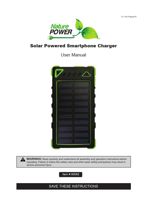
SAVE THESE INSTRUCTIONS Solar Powered Smartphone Charger User ManualItem # 80082V1.1-M 27Sep2019WARNING:Read carefully and understand all assembly and operation instructions before operating. Failure to follow the safety rules and other basic safety precautions may result in serious personal injury.Important Safety InformationThank you for choosing a Nature Power Product.Save the receipt and these instructions. It is important that you read the entire manual to become familiar with this product before you begin using it.This product is designed for certain applications only. the distributor cannot be responsible for issues arising from modification. We strongly recommend this product not be modified and/or used for any application other than that for which it was designed. If you have any question relative to a particular application, Do not use the product until you have first contacted the distributor to determine if it can or should be performed on the product.For technical question please call 1800-588-0590This solar charger is uniquely constructed with integrated Li-polymer 8000mAh battery.It has features of Waterproof, Dustproof, Shockproof .Dual USB output,LED lights.Page 2 of 4Never attempt to open or disassemble the solar charger.Never subject the solar charger to knock or blow.Do not let children play with the solar charger.The solar charger is waterproof but only for rains. Never be immersed in water or any other liquid.Do not leave the solar charger in airtight space when sunshine charging such as in car,may cause the maximum operating temperature(65℃)being exceeded.Do not throw the solar charger into the fire.Parts List1, Charging the solar charger via the solar panel.Place the solar charger under sunlight. the green LED indicator will keep on when the solar charger is charging by sunlight. When the solar charger is fully charged, LED indicators will be off.NOTE: Solar charging is only emergency charging method,please avoid prolonged exposure under the burning sun.2, Charging the solar charger from an external power source.Connect the solar charger's cable to a computer or laptop USB port, USB car charger or USB AC charger. blue led indicators are flashing to indicate that the solar charger is being charged. when the solar charger is fully charged. led indicators will be off.An external power source takes 5-8 hours to fully charge the solar charger.Page 3 of 43, Charging device.after 20 seconds.4, LEDKeep pressing the button for 2 seconds to turn on the 20LED light.Keep pressing the button for 2 times to turn on the single LED flashlight. 2 more times to turn off.When the 20LEDs on, single press the button to reduce luminance;Under low-light mode, single press the button to turn into SOS signal mode;Under SOS signal mode, single press the button to turn back to high light mode;Under high-light mode, pressing the button for 2 seconds to turn off the 20LED light.5, Power indication:Press the button to check the remain battery capacityLED Light(●ON ○OFF) Capacity○○○○ 0%●○○○ 0%-25%●●○○ 25%-50%●●●○ 50%-75%●●●● 75%-100%NOTE:1, When the solar charger is in use and the remained capacity in solar charger is less than 2%, the solar charger will automatically shut off in order to avoid over-discharge of the battery. When the solar charger begins to recharge, it takes 3 minutes before it can output any charging current.2, Because of the special Settings of Apple Corp, please use the apple original data cables when charging for Apple products.3, The Waterproof design can effectively avoid the accident in the process of use, but should avoid power bank in the water or other dangerous environments.Limited WarrantyNature Power warrants our products to the original purchaser that this product is free from d efects in materials and workmanship for the period of 1 year from date of purchase, In the case of pro duct defect, contact Nature Power customer service to receive trouble shooting. If defective part or unit s hould be returned, a Return Authorization Number must be issued by Nature Power and the defective part or unit should be returned to the authorized location at the purchasers’ expense. A dated proof of p urchase is required to receive warranty service. Once received at authorized location and defect prove s to be the result of defective material and workmanship, the defective part or unit will be replaced at w arrantors’ option and returned to the original purchaser at warrantors’ expense. No refunds will be gran ted by the warrantor, in the event of buyer’s remorse please contact your point of purchase within and in adherence to their return policy. Refunds are granted at the retailers’ discretions.Please contact Nature Power Products to acquire more information:1-800-588-0590****************************Made in ChinaPage 4 of 4。
Operating manualSolar charge controller10.10 A / 8.8 A / 6.6 APlease read these instructions completely before installation!1. About this manualThese operating instructions are part of the product. Read these operating instructions carefully before use, keep them over the entire lifetime of the product, and pass them on to any future owner or user of this product.This manual describes the installation, function, operation and maintenance of the solar charge controller. These operating instructions are intended for end customers.A technical expert must be consulted in cases of uncertainty.2. SafetyThe solar charge controller may only be used in PV systems for charging and controlling lead-acid batteries in accordance with this operating manual and the charging specifications of the battery manufacturer.The solar charge controller may only be connected to the local loads and the battery by trained personnel and in accordance with the applicable regulations. Follow the installation and operating instructions for all components of the PV system.No energy source other than a solar generator may be connected to the solar charge controller. Follow the general and national safety and accident prevention regulations.Keep children away from PV systems. Do not use the solar charge controller in dusty environments, in the vicinity of solvents or where inflammable gases and vapours can occur. No open fires, flames or sparks in the vicinity of the batteries. Ensure that the room is adequately ventilated. Check the charging process regularly.Follow the charging instructions of the battery manufacturer. Battery Acid splashes on skin or clothing should be immediately rinse with plenty of water. Seek medical advice.Do not operate the solar charge controller when it does not appear to function at all. The solar charge controller or connected cables are visibly damaged or loose. In these cases immediately remove the solar charge controller from the solar modules and battery.3. FunctionsThe solar charge controller monitors the state of charge of the battery bank, controls the charging process, controls the connection/disconnection of loads. This optimises battery use and significantly extends its service life.The following protection functions are part of the basic function of the controller: Overcharge protection ; Deep discharge protection ; Battery undervoltage protection ; Solar module reverse current protection.4. Installation4.1 Mounting location requirementsDo not mount the solar charge controller outdoors or in wet rooms. Do not subject the solar charge controller to direct sunshine or other sources of heat. Protect the solar charge controller from dirt and moisture.Mount upright on the wall (concrete) on a non-flammable substrate. Maintain a minimum clearance of 10 cm below and around the device to ensure unhindered air circulation. Mount the solar charge controller as close as possible to the batteries (with a safety clearance of at least 30 cm).4.2 Fastening the solar charge controllerMark the position of the solar charge controller fastening holes on the wall.Drill 4 Ø 6 mm holes and insert dowels. Fasten the solar charge controller to the wall with the cable openings facing downwards, using 4 oval head screws M4x40 (DIN 7996).4.3 ConnectionUse an wire size suited to the current ratings of the charge controller, e.g. 6mm² for 10A, 5 mm² for 8A, 4 mm² for 6A, 3 mm² for 5A for cable length of 10 m.An additional external 20A fuse (not provided) must be connected to the battery connection cable, close to the battery pole. The external fuse prevents cable short circuits.Solar modules generate electricity under incident light. The full voltage is present, even when the incident light levels are low. Protect the solar modules from incident light during installation, e.g. cover them.Never touch not isolated cable ends. Use only insulated tools. Ensure that all loads to be connected are switched off. If necessary, remove the fuse.Connections must always be made in the sequence described below.1st step: Connect the batteryConnect the battery connection cable with thecorrect polarity to the middle pair of terminalson the solar charge controller (with the batterysymbol).If present, remove any external fuse. Connectbattery connection cable A+ to the positivepole of the battery. Connect batteryconnection cable A– to the negative pole ofthe battery. Insert the external fuse in thebattery connection cable.If the connection polarity is correct, the infoLED illuminates green.2nd step: Connect the solar moduleEnsure that the solar module is protected from incident light (cover it or wait for night).Ensure that the solar module does not exceed the maximum permissible input current.First connect the M+ solar module connection cable to the correct pole of the left pair ofterminals on the solar charge controller (with the solar module symbol), then connect theM– cable. Remove the covering from the solar module.3rd step: Connect loadsFirst connect the L+ load cable to the correct pole of the right pair of terminals on the solarcharge controller (with the lamp symbol), then connect the L– cable. Insert the load fuse orswitch on the load.Notes : Connect loads that must not be deactivated by the solar charge controller deepdischarge protection, e.g. emergency lights or radio connection, directly to the battery.Loads with a higher current consumption than the device output can be directly connectedto the battery. However, the solar charge controller deep discharge protection will no longerintervene. Loads connected in this manner must also be separately fused.4th step: Final workFasten all cables with strain relief in the direct vicinity of the solar charge controller(clearance of approx. 10 cm).5. LED displaysLED Status Meaningilluminates green normal operationInfo LEDflashes slowly red* system fault- too high charging current- overload / short circuit- overheatedtogether with red LED :- too low battery voltagetogether with green LED :- too high battery voltageflashing quickly* battery empty, low voltage disconnectionprewarning, loads still onBatteryredLED flashing slowly* deep discharge protection active (LVD), loadsdisconnectedilluminates battery weak, loads are onBatteryyellowLEDflashes slowly yellow* LVD reconnection setpoint has not yet beenreached, loads still disconnectedilluminates battery goodBatterygreenLEDflashes quickly green* battery full, charge regulation active*flashing slowly: 0,4Hz: 4 times in 10 second, flashing quickly: 3Hz: 3 times in 1 second6. GroundingThe components in stand-alone systems do not have to be grounded – this is not standardpractice or may be prohibited by national regulations (e.g.: DIN 57100 Part 410: Prohibitionof grounding protective low voltage circuits). Ask your dealer for technical assistance.7. Lightning protectionIn systems subjected to an increased risk of overvoltage damage, we recommendinstalling additional lightning protection / overvoltage protection to reduce dropouts.Ask your dealer for technical assistance.8. MaintenanceThe solar charge controller is maintenance-free.All components of the PV system must be checked at least annually, according to thespecifications of the respective manufacturers. Ensure adequate ventilation of the coolingelement. Check the cable strain relief. Check that all cable connections are secure. Tightenscrews if necessary. Check corrosion on terminals.9. Faults and remediesNo display : Check battery polarity and external fuse. Or battery voltage is too low orbattery defective.Battery is not charged : Check if solar modul is connected with correct polarity or if shortcircuit at the solar input. If solar module voltage is lower than battery voltage or if solarmodule is defective the battery cannot be charged.Battery displays jumps quickly : Battery voltage changes quickly. Large pulse currentscause voltage fluctuation. Battery is too small or defective. Ask your dealer for technicalassistance.The following faults do not destroy the controller. After correcting the fault, the device willcontinue to operate correctly:* solar module short circuits * reverse solar module polarity *2* short circuits at load output * excessive load current* reversed battery polarity *1* solar module overcurrent* device overtemperature * overvoltage at the load output10. Legal guaranteeAccording to the German legal requirements, for this product the customer has a 2 yearlegal guarantee.The seller will remove all manufacturing and material faults that occur in the product duringthe legal guarantee period and affect the correct functioning of the product. Natural wearand tear does not constitute a malfunction.Legal guarantee does not apply if the fault can be attributed to third parties, unprofessionalinstallation or commissioning, incorrect or negligent handling, improper transport, excessiveloading, use of improper equipment, faulty construction work, unsuitable constructionlocation or improper operation or use.Legal guarantee claims shall only be accepted if notification of the fault is providedimmediately after it is discovered. Legal guarantee claims are to be directed to the seller.The seller must be informed before legal guarantee claims are processed.For processing a legal guarantee claim an exact fault description and the invoice / deliverynote must be provided. The seller can choose to fulfil the legal guarantee either by repair orreplacement.If the product can neither be repaired nor replaced, or if this does not occur within asuitable period in spite of the specification of an extension period in writing by thecustomer, the reduction in value caused by the fault shall be replaced, or, if this is notsufficient taking the interests of the end customer into consideration, the contract iscancelled. Any further claims against the seller based on this legal guarantee obligation, inparticular claims for damages due to lost profit, loss-of-use or indirect damages areexcluded, unless liability is obligatory by German law.11. Technical DataSteca Solsum F 6.6F 8.8F 10.10FSystem voltage 12 V (24 V)Own consumption < 4 mADC input sideOpen circuit voltage solar module(at minimum operating temperature)< 47 VModule current 6 A 8 A 10 ADC output sideLoad current 6 A 8 A 10 AEnd of charge voltage 13.9 V (27.8 V)Boost charge voltage 14.4 V (28.8 V)Reconnection voltage (SOC / LVR) *³> 50 % / 12.4 V … 12.7 V(24.8 V … 25.4 V)Deep discharge protection (SOC / LVD) *³< 30 % / 11.2 V … 11.6 V(22.4 V … 23.2 V)Operating conditionsAmbient temperature -25 °C … +50 °CFitting and constructionTerminal (fine / single wire) 4 mm2 / 6 mm2 - AWG 12 / 9Degree of protection IP 32Dimensions (X x Y x Z) 145 x 100 x 24 mmWeight approx. 150 g*1Solsum is protected against reverse battery polarity together with polarity protectedloads. Reverse battery polarity combined with short circuited or polarised load couldcause damages in load or regulator*2Avoid reverse module polarity in a 24V system*3Lower value for nominal current, higher value for lowest currentInfo LED Battery LEDsManufactured in aDIN EN ISO 9001:2000 facilitySolsum / Z02 / Version 1104/ 730.930。
太阳能智能充电器/移动电源一、产品介绍:本产品是一款多用途的太阳能智能充电器/移动电源,内置高容量可充电聚合物锂电池,太阳能电池板功率最高可达1.6w。
通过智能MCU输出多组电压,可随时随地对你的手机、数码相机、PDA、PSP、GPS、DV、MP3、MP4家庭节能设备等进行充电或供电。
本产品具有安全可靠,容量大,寿命长,功能多等优点。
金属外壳设计、时尚高雅、携带方便。
二、使用方法:注:本产品在初次使用时,请在使用前对本产品进行两次以上完全充、放电,以提高内置电池的使用效率。
请按下面步骤使用:1、使用之前请给本产品充电。
有三种方法可选择:A、太阳能充电:打开产品,放置于太阳直射处或强光上,太阳光将自动转化为电能自动为内置的锂电池进行充电。
此时产品的LED指示灯为红色,表示正在充电,当电池充满后,LED指示灯将变为绿色。
(内部设计电路有自动断电保护功能)B、电脑USB对产品充电:将产品用USB线连接到电脑USB端口,此时产品的LED指示灯为红色,表示正在充电,当电池充满后,LED指示灯将变为绿色。
(内置先进的电源管理芯片不会对你的PC产生任何的危害)C、用交流适配器充电:充电时USB指示灯会亮起,产品的LED指示灯为红色,表示正在充电,当电池充满后,LED指示灯将变为绿色,并关闭所有的输出。
另外,还可使用车载充电器对本产品充电。
2、当给您的手机或数码产品充电前,请仔细查看您的产品说明书或电源适配器,了解您产品的充电电压,然后按ON/OFF按钮(3秒一5秒)即可开机,开机时,红色LED电压指示灯亮,开机后产品默认输出4.8V,长按调节按钮(3秒一5秒)即可以调节输出4.8、5.8V、8.4V、9.0V。
每长按一次,可调整一次电压输出,调节好电压后,将充电转换线的USB 5P插头连接到本产品,再将另一头与相应的转接头连接,然后再连接到您的产品上,即可进行充电。
充电时,在您的手机和数码产品上将显示正在充电的提示,您可以在进行充电的同时使用手机进行通话。
太阳能充电器使用说明太阳能移动电源系列产品,拥有智能调压专利技术,可以调节不同的输出电压及电流。
可以在太阳光下对各类手机或USB接口数码产品直接充电,也可以在太阳光较弱或无阳光条件下通过内置蓄电池放电对手机或USB接口数码产品充电。
适用于出差、旅游、长途乘车船、野外作业等环境的备用电源,具有安全保护、兼容性好,大容量、体积小、使用寿命长、性价比高。
产品规格:1、太阳能硅板峰值功率:1.54W2、工作电压:5.5V(最大)3、充电电流:280mA4、蓄电池容量:2000mAh5、输出电压:4.5~9V(可调)6、输出电流:1A(最大)7、充电时间:8-10hrs(幅照度:100mW/C㎡) 3-4hrs(室内电源:5V/500mA)充电说明:1、在xx下充电充电时,放电开关应置于OFF位置,以免充电缓慢,展开太阳能板放置阳光下,并正射太阳能板.太阳能充电器的Light1灯变为红色,此时光能转化为电能对太阳能充电器电池蓄存电.红色表明内置锂电池蓄存电能不多,如果Light1灯变为橙色,表明锂电池中蓄存电能较高,且电压在3.8V~4.1V.如果Light1灯变为绿色,证明充电器内置电池蓄存电已经饱和.当您合上太阳能面板时Light1灯将熄灭,太阳能面板停止充电.注:如果展开太阳能板,在日光下Light1灯变为红色或橙色时,只是表明太阳能面板电压达到Light1灯亮,而不能证明太阳能板在充电.2、使用AC充电由于没有太阳光或阴天情况下,该用AC充电器的DC头连接太阳能充电器的DC接口.再将AC充电器插入110V或220V交流电,Light1灯将变为红色再由红色变为橙色再到绿色的过程.Light1灯变为绿色.表明内置电池已充满,并断开AC充电器的连接.放电说明:放电时,并将输出电压档位调到适当的电压对充电产品充电,然后根据你需要移动设备选择合适的转接头,也可以用USB插头对数码产品连接一起.并将开关切换到"ON"Light1与Light2同时亮时,Light2亮时表示开始放电,(此时内置电池已充满Light1出现红绿交替闪烁属正常现象,具体参考Light1显示说明),当你外接移动设备充电时,Light2亮时,表明正在对你的移动设备或手机充电,移动设备或手机充满后,请将开关切换到OFF位置,以免电量流失.应用领域:适用于充电电压在4.5~9V移动通讯、数码注意事项:1、强光下不能间段充电(直射太阳能面板)约8小时,可充满内置电池.2、在夏季时请勿将充电器置于车内(车内温度过高).影响电池使用寿命3、请勿隔着玻璃对本充电器进行充电.充电效果差.4、必须在强光下充电,在弱光下(Light1)亮灯,只能代表检测到有光,并非代表已在充电(如在室内照明灯下).所以请勿在弱光下进行充电.5、由于出厂时,每个充电器内所含电量不一致,所以,初次使用充电或放电的时间会不同.6、请勿使用有腐蚀性溶液擦拭本机,以免损害本产品.7、严禁将此产品投入火中,以免引起爆炸。
INSTRUCTION MANUAL PORTABLE SOLAR POWER BANK 8.000MAHCOMPONENTS•Solar power bank•USB cable•Buckle•Compass•User manualTECHNICAL SPECIFICATIONS•Capacity: 8.000mAh•Case material: ABS + PC + Silicone•Battery type: A grade Li-polymer battery •Net weight: 280g•Product size: 139 x 75 x 20mm•Input: 5V/1.0A•Output: 5V/1A, 5V/2.1A•Color: orange, blue, green, red, black, yellow•Solar panel: polycrystalline• 1.2m drop testing passed•Waterproof and dustproof IPX5 certified. HOW TO USE1.Light2.Power button3.Outlet 14.Outlet 25.Inlet6.Solar panelO FIRST TIME USEWe recommend you charge the battery fully beforeusing it for the first time. The capacity should befully optimized after 2–3 times of fully charging anddischarging the unit.O CHARGINGYou can charge the power bank with the includedUSB connector, or the one that comes with yourphone or other rechargeable device. If you do nothave a USB adapter, you can plug your connectorinto your compute r’s USB port. The solar panel isfor emergencies, since it is slower to charge thatway. The stronger the sun, the quicker is its charge.O POWER CONTROL SWITCHFirmly press the power button one time. This willturn on blue light indicators that show you how fullis the power bank.• 1 blue light = the charger needs to berecharged.• 2 blue lights = <25% remaining charge• 3 blue lights = 25–50%• 4 blue lights = 50–75%•5 blue lights = the device is at 75–100% charge(Green lights mean t’s being sun-charged))Firmly press the power button for 2 seconds, andthe LED flashlight will go on. Press once again tocycle through modes (bright light, emergency SOSsignal).Firmly press the power button for 2 seconds again to turn the flashlight off.COMPATIBLE DEVICESMost digital products with 5V 1A or 2A power rating can be charged easily.•wireless earphones•tablets•digital cameras•any USB chargeable phones•mp3/mp4 players•any USB device with the same power rating of 5V 1A or 2A. TROUBLESHOOTINGProblem: my USB chargeable device does not seem to be charging when connected to the solar charger.Solution: please try to use the same connector you would normally charge your USB device with. If that works, it is likely that due to wear and tear of the connector that comes with the solar charger, which is not lining up with your USB device’s port.Problem:the flashlight won’t turn on or off. / The flashlight is stuck on either bright or SOS mode.Solution: To turn the flashlight on you will need to firmly hold the power button for 2 seconds. Once the flashlight is on, simply click the power buttonagain to cycle through different modes. Hold thepower button for 2 seconds again to turn off thelight.Problem: the solar charger does not indicate thegreen light when in the sun or seems to be chargingslowly.Solution: please make sure the charger is underdirect, strong sunlight. Depending on the strengthof the sunlight, green lights will indicate the chargepower.Note: due to the conveniently compact size of thecharger, the size of the solar panel will enable onlya very slow charge time. It only serves as anemergency feature that will allow you to getenough power for that critical phone call.SAFETY PRECAUTIONS1.Keep the battery away from heat sources (likea fire or heater).2.Do not throw the battery into fire or heat thebattery.3.Do not hammer or trample the battery.4.Do not try disassembling the battery in anyway.5.This product is waterproof, but with limits. Itshould not be used under water. It is a safetyfeature that protects internal electronics,when briefly submerged.6.Please note that the charger clip is meant forcarrying on a key chain and is not intended as abelt clip.7.The battery is made from a high grade lithiumpolymer.8.Keep out of reach of small children.e this product in a well-ventilated area; it isnot recommended to place on your car’sdashboard when the windows are up as thiscould damage the product.10.Do not tamper with the internal componentsas this will void the 1-year warranty of yourdevice and could furthermore result in othermalfunctions of the unit.WARRANTYThe warranty is valid for 12 months, and you cansend your claim to the seller (us), through thecontact details listed in the bottom right corner. Tosubmit a warranty claim, send the order numberand date of your purchase.WEEE disposal and recycling symbol. The WEEE symbol is attached to the product in compliance with the EU directive 2012/19/EU on Waste Electrical and Electronic Equipment (WEEE). It is intended to deter the improper disposal of this product and topromote reuse and recycling.。
太阳能充电宝产品规格书型号:JN950编制:_________审核:_________核准:_________客户承认:_________目录1.产品概述 (2)2.产品规格 (2)3.电性参数 (2)4.带载能力及效率图表示意 (4)5.功能描述 (5)6.工作原理 (5)7.安全系统要求 (6)8.环境适应及安全保护 (6)9.包装要求 (7)1.产品概述1.1 本产品是专为移动数码产品设计的智能备用电源。
1.2 本产品适用智能手机、平板电脑、便携影音播放设备、掌上游戏机设备等5V直流输入设备,直流12V 的3W-5W 灯泡照明。
1.3 本产品输入部分采用了锂电池专用充电管理IC ,锂电池使用专用保护电路,实现精确控制电压过充、电压过放、电流过载及短路保护,安全性能高;输出采用高效率DC-DC 升压转换电路;同时采用MCU 微电脑控制管理, 实现负载插入自动开机、充满自停、过流保护、电量检测与显示、超低功耗待机等功能。
采用绿光指示,外观圆润细腻,手感舒适。
2. 产品主要规格型 号 JN950输入(V/A/W) 12.6V/1.5A/18.9W 输入端口 DC¢6.5充电端口 总输出(V/A/W) 5V/2.4A/12W 输出端口 单个USB 输出端口 产品容量(mAh) 6000mAh能量(Wh) 66.6Wh (3并3串) 按 键 按键开启输出 显 示 4绿色电量显示LED 尺寸(mm ) 205*200*68mm重量(g )900g实物图:(需要标注长宽高尺寸,LED 顺序说明)电性参数3.1 保护参数项目详细内容最小值 典型值最大值单位备注拔动按键LED 电量指示灯灯USB 输出口DC ¢6.5mm 或太阳能板输入口DC ¢3.8mm 输出口保护参数配置过充单节过充保护 4.25 4.275 4.30 V单节过充保护延迟时间150 340 500 ms VDD=3.6Vto4.4v 单节过充保护恢复 4.15 4.20 4.25 V过放单节过放保护 2.9 3.05 3.1 V单节过放保护延迟时间80 200 300 ms单节过放保护恢复 3.0 3.10 3.15 V过流放电硬件过流保护4510 A放电软件过流保护 2.2 2.6 2.8 A放电过流保护延迟时间9 12 15 ms短路短路保护有短路恢复方式按键激活短路保护延迟时间200 300 400 μs3.2 输出参数项目详细内容最小值典型值最大值单位备注输出参数配置工作参数持续放电电流 2.0 2.1 2.4 A OUT1 电池3.3V -4.2V放电截止电流10 60 80 mA空载电压4.95.1 5.2 V OUT1 电池3.3V -4.2V带载电压4.755.15 5.2 V OUT1 CC1A电池3.3V-4.2VD+/D-电压短路接法OUT1 空载输出纹波85 100 mV OUT1 CC1.0A 电池3.78V升压转化效率90 92 %OUT1 CC 1A 电池3.78V空载关机延时时间25 30 35 S整机静态电流50 100 uA3.3 充电管理项目详细内容最小值典型值最大值单位备注充电参数配置充电电压12.6 13.0 13.5 V 涓流充电阈值8.7 9.0 9.3 V 恒定充电电流 1.0 1.2 1.5 A 恒定充电电压12.48 12.66 12.75 V充电截止电流150 180 mA3. 效率及动态负载电压示意图效率图70.00%75.00%80.00%85.00%90.00%95.00%100.00%0.51 1.52 2.33.13.33.84OUT1 效率图动态负载电压图4.34.454.64.754.95.055.20.51 1.52 2.33.13.33.84OUT1电压4. 产品基本操作及功能说明5.1 产品基本操作:a) 手动开机:太阳能充电宝不接外设时,拔动开关“ON ”启动输出、绿灯电量指示灯一直显示当前电量。
太阳能智能充电器/移动电源一、产品介绍:本产品是一款多用途的太阳能智能充电器/移动电源,内置高容量可充电聚合物锂电池,太阳能电池板功率最高可达1.6w。
通过智能MCU输出多组电压,可随时随地对你的手机、数码相机、PDA、PSP、GPS、DV、MP3、MP4家庭节能设备等进行充电或供电。
本产品具有安全可靠,容量大,寿命长,功能多等优点。
金属外壳设计、时尚高雅、携带方便。
二、使用方法:注:本产品在初次使用时,请在使用前对本产品进行两次以上完全充、放电,以提高内置电池的使用效率。
请按下面步骤使用:1、使用之前请给本产品充电。
有三种方法可选择:A、太阳能充电:打开产品,放置于太阳直射处或强光上,太阳光将自动转化为电能自动为内置的锂电池进行充电。
此时产品的LED指示灯为红色,表示正在充电,当电池充满后,LED指示灯将变为绿色。
(内部设计电路有自动断电保护功能)B、电脑USB对产品充电:将产品用USB线连接到电脑USB端口,此时产品的LED指示灯为红色,表示正在充电,当电池充满后,LED指示灯将变为绿色。
(内置先进的电源管理芯片不会对你的PC产生任何的危害)C、用交流适配器充电:充电时USB指示灯会亮起,产品的LED指示灯为红色,表示正在充电,当电池充满后,LED指示灯将变为绿色,并关闭所有的输出。
另外,还可使用车载充电器对本产品充电。
2、当给您的手机或数码产品充电前,请仔细查看您的产品说明书或电源适配器,了解您产品的充电电压,然后按ON/OFF按钮(3秒一5秒)即可开机,开机时,红色LE D电压指示灯亮,开机后产品默认输出4.8V,长按调节按钮(3秒一5秒)即可以调节输出4.8、5.8V、8.4V、9.0V。
每长按一次,可调整一次电压输出,调节好电压后,将充电转换线的USB 5P插头连接到本产品,再将另一头与相应的转接头连接,然后再连接到您的产品上,即可进行充电。
充电时,在您的手机和数码产品上将显示正在充电的提示,您可以在进行充电的同时使用手机进行通话。
本文部分内容来自网络整理,本司不为其真实性负责,如有异议或侵权请及时联系,本司将立即删除!
== 本文为word格式,下载后可方便编辑和修改! ==
太阳能充电宝说明书范文
篇一:太阳能充电宝实验报告
电子实训(设计)
课题姓名
学号
专业 11电子信息工程指导教师李老师
第一章绪论
1.1 设计目的
随着通信技术的迅猛发展,化石能源被日益消耗甚至即将面临枯竭,全球能源问题日益严重。
另外人们的环境保护意识越来越强烈,寻找各种清洁能的源来代替化石能源变得尤为重要。
太阳能作为一种可再生资源有取之不尽用之不竭的有点,并且清洁安全。
因此太阳能有着广泛的应用前景。
所以移动电源顺应时代的发展,本文主要介绍自制的简易移动电源,主要利用tp4056充电控制芯片来控制整个电路的运作,电路中还有多种贴片电阻,贴片电容,贴片二极管MDDSS14,和电感,接上5V电源后,会发现LED灯会亮,接不同的电压,灯亮的个数会不一样。
通过这次实训,有了很大的收获。
1.2 设计思路和分析
相信大家多少都接触过太阳能吧,我们接触最多大概有三种:单晶硅,多晶硅,非晶硅。
单晶硅的效率最高,非晶硅的弱光响应最好。
选取的非晶硅尺寸为
50*50 电压4.5伏电流30毫安以及电池芯片管理TP4056
总电路原理图
第二章硬件电路设计
电源稳压器:
电源稳压器选用的是TP4056芯片,TP4056充电控制芯片是一款完整的单节锂
离子电池采用恒定电流/恒定电压线性充电器。
其底部带有散热片的 SOP8 封
装与较少的外部元件数目使得 TP4056充电控制芯片成为便携式应用的理想选择。
TP4056充电控制芯片可以适合 USB 电源和适配器电源工作。
由于采用了
内部 PMOSFET 架构,加上防倒充电路,所以不需要外部隔离二极管。
热反馈可对充电电流进行自动调节,以便在大功率操作或高环境温度条件下对芯片温度
加以限制。
充电电压固定于 4.2V,而充电电流可通过一个电阻器进行外部设置。
当充电电流在达到最终浮充电压之后降至设定值
1/10 时,TP4056充电控制芯片将自动终止充电循环。
当输入电压(交流适配
器或 USB 电源)被拿掉时,TP4056充电控制芯片自动进入一个低电流状态,将电池漏电流降至 2uA 以下。
TP4056充电控制芯片在有电源时也可置于停机
模式,以而将供电电流降至 55uA。
TP4056充电控制芯片的其他特点包括电
池温度检测、欠压闭锁、自动再充电和两个用于指示充电、结束的 LED 状态
引脚。
如图是该芯片的典型电路图:
III
二极管:
二极管的主要特性是单向导电性,也就是在正向电压的作用下,导通电阻很小;而在反向电压作用下导通电阻极大或无穷大。
本品中选用肖特基贴片二极管,
又称肖特基势垒二极管,它属一种低功耗、超高速半导体器件。
最显著的特点
为反向恢复时间极短(可以小到几纳秒),正向导通压降仅0.4V左右。
肖特基(Schottky)二极管的最大特点是正向压降 VF 比较小。
在同样电流的情况下,它的正向压降要小许多。
另外它的恢复时间短。
它也有一些缺点:耐压比较低,漏电流较大。
其多用作高频、低压、大电流整流二极管(比如开关电源次极整
流二极管),续流二极管、保护二极管,也有用在微波通信等电路中作整流二
极管、小信号检波二极管使用。
在通信电源、变频器等中比较常见。
电感
电感通直流,阻交流。
通直流:所谓通直流就是指在直流电路中,电感的作用就相当于一根导线,不起任何作用. 阻交流:在交流电路中,电感会有阻抗,即XL,
整个电路的电流会变小,对交流有一定的阻碍作用。
电感的基本作用:滤波、振荡、延迟、陷波等通直在电子线路中,电感线圈对交流有限流作用,它与电阻器或电容器能组成高通或低通滤波器、移相电路及谐振电路等;变压器可以进行交流耦合、变压、变流和阻抗变换等。
第三章 PCB设计
将移动电源原理图画成PCB图,然后打印在喷了墨的底稿上,再将打印好的纸
与差不多大小的电路板固定到一起到转印机那里转印,约来回5-6次即可将墨
转印到板上,然后拿到腐蚀剂里腐蚀,直到板表面的铜都被腐蚀掉,然后擦干
净拿到钻孔机器去钻孔,最后的过程就是焊接元器件,焊接之前,要先练习一下,因为贴片器件都很小,元器件也很少,很容易焊坏掉。
下图是PCB图:
V
篇二:太阳能充电宝构成与选用方法
太阳能充电宝构成与选用方法:
太阳能充电宝主要由LM2575ADJ和LM3420等构成的充电电路,LM3420监视充
电电器的电压,其输入加至开关集成稳压器LM2575ADJ的反馈端(FB)。
当检
测到用电器满充电电压时,电路停止对电池充电,另外,(LM358)放大器用于增强LM3420的检测能力。
随着通信技术的迅猛发展,化石能源被日益消耗甚至即将面临枯竭,全球能源
问题日益严重。
另外人们的环境保护意识越来越强烈,寻找各种清洁能的源来
代替化石能源变得尤为重要。
太阳能作为一种可再生资源有取之不尽用之不竭
的有点,并且清洁安全。
因此太阳能有着广泛的应用前景。
所以移动电源顺应时代的发展,本文主要介绍自制的简易移动电源,主要利用
tp4056充电控制芯片来控制整个电路的运作,电路中还有多种贴片电阻,贴片
电容,贴片二极管MDDSS14,和电感,接上5V电源后,会发现LED灯会亮,接
不同的电压,灯亮的个数会不一样。
通过这次实训,有了很大的收获。
电源稳压器选用的是TP4056芯片,TP4056充电控制芯片是一款完整的单节锂
离子电池采用恒定电流/恒定电压线性充电器。
其底部带有散热片的 SOP8 封
装与较少的外部元件数目使得 TP4056充电控制芯片成为便携式应用的理想选择。
TP4056充电控制芯片可以适合 USB 电源和适配器电源工作。
由于采用了内部 PMOSFET 架构,加上防倒充电路,所以不需要外部隔离二极管。
热反馈可对充电电流进行自动调节,以便在大功率操作或高环境温度条件下对
芯片温度加以限制。
充电电压固定于 4.2V,而充电电流可通过一个电阻器进行外部设置。
当充电电流在达到最终浮充电压之后降至设定值 1/10 时,TP4056
充电控制芯片将自动终止充电循环。
比如尚信光伏就是这样的产品,主要供应苹果等一线品牌手机的充电器,太阳能与普通款式均有供消费者选择,普通
款式的国产产品可按照尺寸通用,提高了产品与手机的匹配度。
当输入电压(交流适配器或 USB 电源)被拿掉时,TP4056充电控制芯片自动
进入一个低电流状态,将电池漏电流降至 2uA 以下。
TP4056充电控制芯片
在有电源时也可置于停机模式,以而将供电电流降至 55uA。
TP4056充电控制
芯片的其他特点包括电池温度检测、欠压闭锁、自动再充电和两个用于指示
充电、结束的 LED 状态引脚。
篇三:第10组小型太阳能充电宝设计。