18-ASPEN_间歇精馏
- 格式:doc
- 大小:61.00 KB
- 文档页数:2
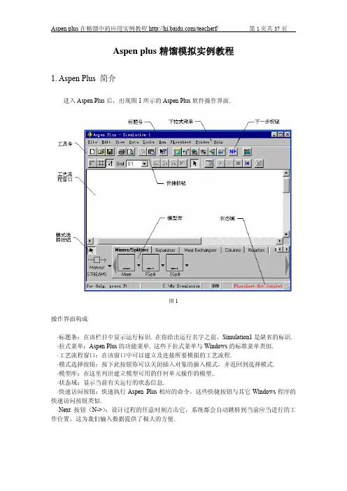
一直想用aspen plus做一个关于间歇精馏的模拟,当开始做之后才发觉困难重重。
间歇精馏和连续精馏差别比较大,面板上好多属性的设置都变了样,位置也改变了。
还多出了夹套蒸汽加热,间歇进料时间设置等。
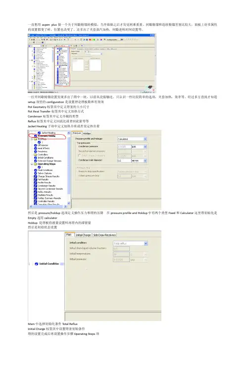
一打开间歇精馏设置发现多出了图中一块,以前从没接触过。
只认识一些比较简单的选项,夹套加热,效率等。
经过多方查找才知道setup项里的configuration是设置理论塔板数和有效项Pot Geometry标签页中定义塔釜的大小尺寸Pot Heat Transfer标签页中定义加热方式Condenser标签页中定义冷凝的类型Reflux标签页中定义回流比或者回流量等等Jacket Heating子项中定义加热介质或者设定热负荷然后是pressure/holdup选项定义操作压力和塔的压降 在pressure profile and Holdup中有两个类型Fixed和Calculator这里塔初始化是Empty选用calculatorHoldup 是塔板持液量设置料再塔内的滞留量然后是初始状态设置Main中选择初始化条件Total RefluxInitial Charge标签页中设置塔釜初始条件塔的设置完成后再设置操作步骤Operating Steps项在End Condition标签页中定义结束精馏的条件当六甲基二硅氮烷的含量为0.05时结束精馏我一直在惦记着还有两个问题没解决,一个是进料的事后属于间歇进料需要设置间歇进料的时间昨天在实验室看书刚刚找到了这方面的内容在全局设置report options中有一个batch operation选项设置进料时间。
躲得好深还有一个问题是设置成丝网填料塔,前面所设置的板数只是理论板要换算成填料高度最后终于找到了,在blocks的internals选项里面packing代表填料塔tray代表筛板塔。
运行完成之后出来结果我的间歇精馏模拟还存在问题,在添加填料性质之前核算都是正确的。

1引言1.1ASPEN PLUS概述Aspen Plus是大型通用流程模拟系统,源于美国能源部七十年代后期在麻省理工学院(MIT)组织的会战,开发新型第三代流程模拟软件。
该项目称为“过程工程的先进系统”(Advanced System for Process Engineering,简称ASPEN),并于1981年底完成。
1982年为了将其商品化,成立了AspenTech公司,并称之为Aspen Plus。
该软件经过20多年来不断地改进、扩充和提高,已先后推出了十多个版本,成为举世公认的标准大型流程模拟软件,应用案例数以百万计。
全球各大化工、石化、炼油等过程工业制造企业及著名的工程公司都是Aspen Plus 的用户。
1.2精馏塔概述精馏塔是进行精馏的一种塔式汽液接触装置,又称为蒸馏塔。
有板式塔与填料塔两种主要类型。
根据操作方式又可分为连续精馏塔与间歇精馏塔。
蒸气由塔底进入。
蒸发出的气相与下降液进行逆流接触,两相接触中,下降液中的易挥发(低沸点)组分不断地向气相中转移,气相中的难挥发(高沸点)组分不断地向下降液中转移,气相愈接近塔顶,其易挥发组分浓度愈高,而下降液愈接近塔底,其难挥发组分则愈富集,从而达到组分分离的目的。
由塔顶上升的气相进入冷凝器,冷凝的液体的一部分作为回流液返回塔顶进入精馏塔中,其余的部分则作为馏出液取出。
塔底流出的液体,其中的一部分送入再沸器,加热蒸发成气相返回塔中,另一部分液体作为釜残液取出。
1.2.1 精馏塔的分类气-液传质设备主要分为板式塔和填料塔两大类。
精馏操作既可采用板式塔,也可采用填料塔,填料塔的设计将在其他分册中作详细介绍,故本书将只介绍板式塔。
板式塔为逐级接触型气-液传质设备,其种类繁多,根据塔板上气-液接触元件的不同,可分为泡罩塔、浮阀塔、筛板塔、穿流多孔板塔、舌形塔、浮动舌形塔和浮动喷射塔等多种。
板式塔在工业上最早使用的是泡罩塔(1813年)、筛板塔(1832年),其后,特别是在本世纪五十年代以后,随着石油、化学工业生产的迅速发展,相继出现了大批新型塔板,如S型板、浮阀塔板、多降液管筛板、舌形塔板、穿流式波纹塔板、浮动喷射塔板及角钢塔板等。
带有中间储罐的间歇精馏的动态模拟与控制王晓红;谢力;张远鹏;于新帅【摘要】使用Aspen Plus和Aspen Plus Dynamics模拟了用于分离正己烷/正庚烷/正辛烷三元体系的中间储罐间歇精馏过程.首先在稳态模拟中按照连续精馏流程的模拟方法确定稳态模拟流程,在动态模拟中关闭进料和产品出口阀门,来实现间歇精馏在Aspen Plus和Aspen Plus Dynamics中的模拟.在Aspen Plus Dynamics中研究带有高选择器的组成控制结构和温度控制结构.两种控制结构都能使产品纯度达到分离要求.结果显示:就产品纯度稳定性而言,带有高选择器的温度控制结构相比组成控制结构有更好的控制性能.%The middle vessel batch distillation process for separating the n-hexane/n-hexane/octane ternary system was simulated using Aspen Plus and Aspen Plus Dynamics.The steady state flowsheet of the middle vessel batch distillation was simulated in the manner of continuous distillation in the steady-state simulation,and then the feed and outlet valve was closed in dynamic simulation to implement the simulation of batch distillation process in Aspen Plus and Aspen Plus Dynamics.The composition control structure and the temperature control structure with high selectorswere studied in Aspen Plus Dynamics.The separation requirements are both meet under the two kinds of control structure.The results shows that the temperature control structure with high selectors has better control performance than thecomposition control structure with high selectors in terms of the stability of product purity.【期刊名称】《青岛科技大学学报(自然科学版)》【年(卷),期】2018(039)002【总页数】7页(P37-43)【关键词】中间储罐;间歇精馏;动态控制【作者】王晓红;谢力;张远鹏;于新帅【作者单位】青岛科技大学化工学院,山东青岛266042;青岛科技大学化工学院,山东青岛266042;青岛科技大学化工学院,山东青岛266042;青岛科技大学化工学院,山东青岛266042【正文语种】中文【中图分类】TQ028正己烷/正庚烷/正辛烷是石油加工过程中常见的混合物。


如何使用A S P E N软件模拟完成精馏的设计和控制马后炮Pleasure Group Office【T985AB-B866SYT-B182C-BS682T-STT18】如何使用ASPEN TM 软件模拟完成精馏的设计和控制威廉·L·鲁平博士第6 章:使用稳态计算选择控制结构Steadt-state Calculations for Control Structure Selection 在我们转入将稳态模拟转化为动态模拟细节讨论之前,要先讨论一些重要的稳态模拟计算方法。
因为经常被用于精馏设计中帮助为其选择一个实用且高效的控制结构,。
故此类讨论可能是一定意义的。
绝大部分精馏塔的设计是为了将两种关键组分分离获得指定的分离效果。
通常是两个设计自由度指定为馏出物中重关键组分的浓度和塔底产品中轻关键组分的浓度。
因此,在精馏塔的操作和控制中,“理想的”控制结构需测定两股产品的组成并操控两输入变量(如,回流流量和再沸器的输入热量),从而能够达到两股产品中关键组分的纯度要求。
然而,由于一些现实的原因,很少有精馏塔使用这种理想的控制结构。
组分检测仪通常购价昂贵且维修成本高,其可靠性对连续在线控制而言,有时略显不足。
如果使用色层法,还会在控制回路中引入死时间。
此外,不使用直接测量组分法,通常也有可能取得非常高效的控制效果。
温度测量被广泛应用于组分的推理控制。
温度传感器廉价而又可靠,在控制回路上只有很小的测量滞后。
对恒压二元体系,温度与组成是一一对应相关的。
这在多组分体系中不适用,但精馏塔中合适位置的温度通常能够相当准确地提供关于关键组分浓度的信息。
在单端控制结构中,只需控制某块塔板的温度;选择剩下的“控制自由度”时应使产品质量可变性最小。
例如,确定一定的回流比RR 或者固定回流与进料流量的比值R/F。
有时候,需要控制两个温度(双温控制系统)。
我们将在本章中讨论这些被选方案。
如果选择使用塔板温度控制,那么问题便是选择最佳一块或数块塔板,该处的温度保持恒定。
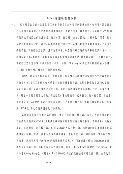
Aspen精馏模拟的步骤一、板式塔工艺设计首先要知道工艺计算要算什么?要得到那些结果?如何算?然后再进行下面的计算步骤。
其次要知道你用的软件(或软件模块)能做什么,不能做什么?你如何借助它完成给定的设计任务。
设计方案,包括设计方法、路线、分析优化方案等,应该是设计开题报告中的一部份。
没有很好的设计方案,具体作时就会思路不清晰,足见开题的重要性。
下面给出工艺设计计算方案参考,希望借此对今后的结构和强度设计作一个详细的设计方案,明确的一下接下来所有工作详细步骤和方法,以便以后设计工作顺利进行。
板式塔工艺计算步骤1.物料衡算(手算)目的:求解aspen 简捷设计模拟的输入条件。
容:(1) 组份分割,确定是否为清晰分割;(2)估计塔顶与塔底的组成。
得出结果:塔顶馏出液的中关键轻组份与关键重组份的回收率参考:《化工原理》有关精馏多组份物料平衡的容。
2.用简捷模块(DSTWU)进行设计计算目的:结合后面的灵敏度分析,确定合适的回流比和塔板数。
方法:选择设计计算,确定一个最小回流比倍数。
得出结果:理论塔板数、实际板数、加料板位置、回流比,蒸发率等等RadFarce 所需要的所有数据。
3.灵敏度分析目的:1.研究回流比与塔径的关系(NT-R),确定合适的回流比与塔板数。
2.研究加料板位置对产品的影响,确定合适的加料板位置。
方法:可以作回流比与塔径的关系曲线(NT-R),从曲线上找到你所期望的回流比及塔板数。
得到结果:实际回流比、实际板数、加料板位置。
4. 用DSTWU再次计算目的:求解aspen塔详细计算所需要的输入参数。
方法:依据步骤3得到的结果,进行简捷计算。
得出结果:加料板位置、回流比,蒸发率等等RadFarce 所需要的所有数据。
5. 用详细计算模块(RadFrace)进行初步设计计算目的:得出结构初步设计数据。
方法:用RadFrace 模块的Tray Sizing(填料塔用PAking Sizing),利用第4步(DSTWU)得出的数据进行精确设计计算。
本科毕业论文(设计)题目:碳酸二甲酯—甲醇体系间歇萃取精馏模拟专业:化学工程与工艺(煤化工方向)****学士学位论文原创性声明本人郑重声明:所呈交的学位论文,是本人在导师的指导下,独立进行研究工作所取得的成果。
除文中已经注明引用的内容外,本论文不含任何其他个人或集体已经发表或撰写过的作品成果。
对本文的研究做出重要贡献的个人和集体,均已在文中以明确方式标明。
本人完全意识到本声明的法律结果由本人承担。
作者签名:日期:关于论文使用授权的说明学位论文作者完全了解延安大学有关保留和使用学位论文的规定,即:本科生在校攻读学士学位期间论文工作的知识产权单位属延安大学,学生公开发表需经指导教师同意。
学校有权保留并向国家有关部门或机构送交论文的复印件,允许学位论文被查阅和借阅;学校可以公布学位论文的全部或部分内容,可以允许采用影印、缩印或其它复制手段保存、汇编学位论文。
保密论文注释:本学位论文属于保密范围,在 2 年解密后适用本授权书。
非保密论文注释:本学位论文不属于保密范围,适用本授权书。
作者签名:日期:导师签名:日期:目录1 前言 (1)1.1碳酸二甲酯—甲醇恒沸体系介绍 (1)1.2间歇萃取精馏原理介绍 (2)1.3萃取剂选择原理[4] (2)1.4萃取精馏的操作特点 (3)1.5 Aspen流程模拟软件简介及应用 (3)1.6 BatchFrac模型简介 (4)1.7主要研究内容 (5)2碳酸二甲酯-甲醇体系分离过程模拟及优化 (5)2.1设计工艺参数 (5)2.2模拟流程的建立[8] (6)2.3重要参数的确定 (6)2.3.1定义物性方法 (6)2.3.2定义进料物流参数 (6)2.3.3定义模块参数 (7)2.4分离工艺过程的运行 (7)2.4.1萃取精馏阶段 (7)2.4.2过渡液回收阶段 (9)2.4.3萃取剂回收阶段 (11)2.5灵敏度分析及过程优化 (12)2.5.1灵敏度分析简介 (12)2.5.2萃取剂进料量 (13)2.5.3萃取剂进料位置 (13)2.5.4萃取剂进料温度 (14)2.5.5回流比 (15)2.5.6精馏塔塔板数 (15)3结果与讨论 (16)参考文献 (16)附录 (17)碳酸二甲酯—甲醇体系间歇萃取精馏模拟摘要:本论文利用Aspen Plus流程模拟软件,基于UNIFAC活度系数模型,采用半连续加入萃取剂、回流比恒定馏出液组成逐渐减小的间歇萃取精馏方法,以碳酸乙烯酯为萃取剂,运用灵敏度分析法分析影响分离碳酸二甲酯-甲醇效果的各工艺参数,并且根据此得出最优分离条件,得到当萃取剂进料量为75kmol/sec,第4块塔板进料,进料温度为25℃,间歇精馏塔理论塔板数为20块,回流比为5时分离取得最优效果,精制碳酸二甲酯纯度达到0.995,甲醇馏出物、萃取剂回收纯度均大于等于0.99。
间歇精馏讲解
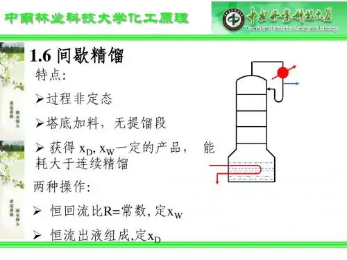
间歇精馏是一种常见的分离和纯化有机化合物的方法。
它主要适
用于不同沸点的化合物,通过温度的变化使它们分别蒸发、凝结,最
终得到纯净的化合物。
在间歇精馏过程中,需要一个精细的装置。
通常采用双颈烧瓶,
烧瓶装有导管和热交换器,可以用来控制温度和压力。
还需要连接一
个冷凝水管,以便冷却蒸气并使其转化成液体。
此外,还需要使用温
度计、计时器和其他辅助设备来精确控制操作。
在进行间歇精馏时,首先将混合物放入烧瓶中,并加热至混合物
开始汽化。
这时,蒸汽通过导管进入热交换器,在那里它与冷却水接
触并冷却,逐渐转变为液体。
得到的液体收集在另一个烧瓶中,在此
过程中,可以通过温度的变化来控制分离的化合物。
间歇精馏可以广泛应用于有机化合物的分离,如酯、醇、酚、醛、酮、酸等。
它不仅可用于合成工艺中的分离和提纯,还可用于从天然
中提取组分,如植物和动物油脂。
此外,间歇精馏还可以协助分离和测量化合物的揮发度和沸点,
以及用于分析和确定它们的纯度,从而确定适合于不同的应用的最佳
条件。
总之,间歇精馏是一种广泛使用的有效分离方法,它的技术要求
较高,需要精密设备和技能操作。
但是,通过对间歇精馏的逐步理解
和掌握,你将能够通过精确的温度控制和操作技巧,成功分离和纯化你的化合物。
Aspen间歇精馏模拟教程Aspen间歇精馏模拟教程Use this Getting Started section to become familiar with the steps to set up a batch simulation using Aspen Batch Modeler. You will be modeling a system to recover methanol from a mixture of methanol and water.The objective is to separate methanol from the mixture with a purity of 99%. This mixture is not ideal given the polarity of the molecules; therefore, for a working pressure of 1atm, you will choose NRTL to model its physical properties.There are four steps in this process. Click a step to go the instructions for the step.Step 1 – Set up the Properties for Aspen Batch ModelerStep 2 – Enter structural data and specifications for the Aspen Batch Modeler block Step 3 – Enter Operating StepsStep 4 – Run the simulation and view the resultsStep 1 - Set up the Properties for Aspen Batch ModelerWe want to define a Properties file that has the following defined.Components Property MethodWater NRTLMethanolTo define this Properties file, follow the steps below.To set up the Problem Definition file from within Aspen Batch Modeler:1. Start Aspen Batch Modeler.2. On the Species form, click Edit Using Aspen Properties.This will start Aspen Properties.3. Enter the Components:Component ID Component name Formula WATER WATER H2O METHANOL METHANOL CH4OTip: You can use the Next button4. Click the Next button Properties Specifications form.5. On the Properties Specifications form, in the Property method field, select NRTL. Tip: Clicking the pull-down arrow on the field and typing N (the first letter of the property method name) takes you to the right choice much faster than just scrolling down the long list.6. Click NextYou are taken to the binary parameters forms, where you can view the binary parameters that will be used for Properties Calculations.7. Click NextYou are prompted to click one of the options shown below.8. There is no need for further input, so click OK to run the property setup.9. Close Aspen Properties by clicking File | Exit.You are prompted with the following:10. Click Yes to save the file.The Property setup is now complete.Step 2 - Enter structural data and specifications for the Aspen Batch Modeler blockThe column has been designed as follows:Configuration10 Stages (this includes eight trays, condenser and pot)Vapor-liquid separationPot GeometryElliptical head1m diametervolume of 1m3OverheadTotal CondenserDistillate mole flow rate = 4.5kmol/hrReflux drum is present(no need to enter dimension because we are defining fixed pressure profile/holdups; therefore reflux holdup will be entered) Pressure/HoldupsPressure profile is fixedCondenser pressure 1.01325 barColumn Pressure Drop 0.1 barHoldupsReflux Drum liquid holdup: 0.02 m3Stage holdup: 0.005 m3Heat TransferDuty: 150 kWReceiversOne receiver for liquid distillateInitial condition: total refluxInitial ConditionsInitial Charge18kmol of materialComponent mole fractionMethanol: 0.4Water: 0.6To Enter the Data1. Set the configuration to Batch Distillation Column, specify the number of stages and ensure valid phases are Vapor-Liquid on the Configuration Main form10 Stages (this includes eight trays, condenser, and pot)Vapor-liquid separation2. On the Setup | Pot Geometry tab , type the pot dimensions:Elliptical; 1m diameter; volume of 1m33. Click the Overhead form. On the Condenser tab, click Total for Total condenser.4. On the Reflux tab, type the distillate mole flow rate:Distillate mole flow rate = 4.5kmol/hrReflux drum is presentNote: You need not enter dimension because we are defining fixed pressure profile/holdups. Therefore, reflux holdup will be entered.5. Click the Jacket Heating form under Setup. On the Jacket Heating tab, enter the pot conditions:Duty: 150 kW6. Click Pressure/Holdups | Pressure.7. On the Pressure tab, type the pressure profile:Pressure profile is fixed.Condenser pressure 1.01325 barColumn Pressure Drop 0.1 bar8. On the Holdups tab, type the reflux and stage holdup information: Reflux Drum liquid holdup: 0.02 m3 Stage holdup: 0.005 m39. Click Receivers | Distillate.10. On the Distillate tab, define one liquid distillate receiver.11. Click Initial Conditions | Main.12. On the Main tab, in the Initial condition field, click Total reflux.13. On the Initial Charge tab, define the following:Total initial charge: 18 kmol of materialComponent mole fraction:Methanol: 0.4Water: 0.6Note: Do not forget to save your work regularly.To save your file for the first time:1. On the File menu, click Save As.2. In the File name field, type a name, or select a file name to overwrite an existing file:3. Click Save.Step 3 - Enter Operating StepsThere are two Operating Steps:1. Start product draw maintaining a distillate flow rate of 4.5 kmol/hr.2. Stop when the mole fraction of water in the distillate receiver approaches 0.01 from below. The batch is complete. To create the required operating steps to run the problem:1. Click Operating Steps and enter distil in the Name column of the Operating Steps table.This will create the first operating step distil.2. On the Changed Parameters tab, create an operating step to distill the methanol by maintaining a distillate flow rate of 4.5 kmol/hr.3. On the End Condition tab, specify as the end condition the mole fraction of water in the distillate receiver approaching the value of 0.01 from below.Step 4 - Run the simulation and view the resultsThe simulation is now ready to run.Before running the simulation, it is a good idea to create plots for key variables such as: the composition and holdup in the Receiverthe composition and temperature in the potand so onTo create plots for key variables:1. On the Plots form, click the Temperature and Composition to create time plots for pot temperature and mole fractions.2. Use the Custom plots feature to create plots of the receiver holdups and compositions. Click New on the Custom plots table and specify H2O_distil as the name of the plot.3. Go to the Holdups Summary Results\Distillate tab. Select the field that displays the WATER mole fraction and drag it on to the plot (H2O_distil) created in the previous step.4. Use the same approach to create plots of holdups in the receiver and/or the plot.5. You can change the time units displayed in the plots by clicking the Run Options toolbar button Select the time units in which the user interface should display time field.14. Click the Run button and view the Simulation Messages window for any relevantmessages.Once the problem has run successfully you can view results in the forms.Batch time: 1.49 hours/ 89.4 minutesPot temperature: 101.05 ℃Methanol recovery: 6.636 kmolNote: It is always good practice to restart your simulation in order to restore it to time zero before saving your work.。