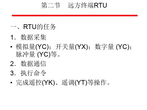
chapter5-2远方终端RTU2
- 格式:ppt
- 大小:378.50 KB
- 文档页数:11

RTU控制装置的安装与配置技巧1. 简介远程终端单元(Remote Terminal Unit,RTU)是一种用于监控和控制远程设备的电子设备。
它通常用于工业控制系统(Industrial Control Systems,ICS)中,用于收集传感器数据、执行控制命令和将数据传输回中央监控系统。
本文档将介绍RTU控制装置的安装与配置技巧,帮助您更好地使用RTU。
2. 安装步骤2.1 准备工作- 确保RTU设备已从包装盒中取出,并检查设备外观是否有损坏。
- 准备所需的工具和配件,如螺丝刀、剥线钳、接线端子等。
- 确保RTU设备的电源供应正常,并根据设备要求选择合适的电源。
2.2 安装RTU设备1. 将RTU设备放置在合适的位置,确保设备通风良好,避免直接暴露在阳光下。
2. 使用螺丝刀将RTU设备固定在支架或机架上,确保设备稳定。
3. 将电源线连接到RTU设备的电源接口,并确保电源线符合相关安全标准。
2.3 连接传感器和执行器1. 根据RTU设备的接线图,使用适当的线缆和接线端子连接传感器和执行器。
2. 确保连接正确无误,并使用绝缘材料固定线缆,防止线缆松动或短路。
3. 测试传感器和执行器的连接是否正常,确保数据传输和控制命令的准确性。
3. 配置步骤3.1 配置RTU设备1. 打开RTU设备的配置软件,根据设备型号和需求选择合适的配置选项。
2. 配置RTU设备的基本参数,如通信协议、数据采集周期、报警阈值等。
3. 根据需要配置RTU设备的输入输出参数,如传感器类型、执行器控制命令等。
3.2 配置通信接口1. 根据监控系统的需求,配置RTU设备的通信接口,如RS-232、RS-485、以太网等。
2. 设置合适的通信速率、数据位、停止位和校验方式等参数。
3. 测试通信接口的连接是否正常,确保数据传输的稳定性和可靠性。
3.3 配置报警和通知1. 根据需求配置RTU设备的报警条件和通知方式,如短信、邮件等。
2. 设置合适的报警阈值和报警级别,确保及时发现和处理异常情况。
吉林市凯赛电厂远动终端(RTU)设备技术协议二零一零年四月吉林省电力有限公司吉林市调度通讯所与长春华信电力成套设备有限公司,经协商就吉林市凯赛电厂RTU远动装置,达成如下协议:1总则1.1本技术要求适用于吉林市凯赛电厂工程远动终端(RTU)设备,它提出了该装置的功能设计、结构、性能、安装和试验等方面的技术要求。
1.2本设备技术要求提出的是最低限度的技术要求,并未对一切技术细节作出规定,也未充分引述有关标准和规范的条文,卖方应提供本规范书和工业标准的优质产品。
1.3如果卖方没有以书面形式对本规范书的条文提出异议,则意味着卖方提供的设备完全符合本规范书要求。
1.4本设备要求所使用标准如遇与卖方所执行标准不一致时,按较高标准执行。
1.5本设备要求经买、卖双方确认后作为订货合同的技术附件,与合同正文具有同等法律效力。
1.6本设备规范书未尽事宜,由买、卖双方协商解决。
1.7设备采用的专利等涉及的全部费用均被认为已包含在设备报价中,供方应保证需方不再另外承担与设备专利有关的一切责任。
1.8卖方提供的远动装置必须是高质量的设备,这些设备应是技术先进并经过相同参数两台三年以上成功运行实践证明是成熟可靠的产品。
1.9买方具有本技术规范书的最终解释权。
2工程概况吉林凯赛电厂远动终端(RTU)设备配置容量按照电气主接线图配置,考虑一定的备用容量。
3技术要求3.1范围本文规定了66kV 凯赛电厂变电站远动终端(RTU)的功能要求、性能指标、系统配置、系统安装运行环境等指标的要求。
3.2规范性文件GB/T 14429—93 远动设备及系统术语GB4208 外壳防护等级GB2423 电工电子产品基本环境试验规程GB50171 电气装置安装工程盘、柜及二次回路结线施工及验收规程GB/T 6593 电子测量仪器质量检测规则GB/T 13729 远动终端通用技术条件GB/T 13730 地区电网数据采集与监控系统通用技术条件GB/T 15153 运动设备及系统工作条件环境条件和电源GB/17621.1 电磁兼容试验和测量技术抗扰度试验总论GB/17621.2 电磁兼容试验和测量技术静电放电抗扰度试验GB/17621.3 电磁兼容试验和测量技术射频电磁场辐射抗扰度试验GB/17621.4 电磁兼容试验和测量技术浪涌(冲击)抗扰度试验GB/17621.5 电磁兼容试验和测量技术电快速瞬变脉冲群抗扰度试验GB/17621.6 电磁兼容试验和测量技术射频场感应的传导骚扰抗扰度GB/17621.8 电磁兼容试验和测量技术工频磁场抗扰度试验GB/17621.10 电磁兼容试验和测量技术阻尼振荡磁场抗扰度试验GB/17621.11 电磁兼容试验和测量技术电压暂降、短时中断和电压变化抗扰度试验GB/17621.12 电磁兼容试验和测量技术振荡波抗扰度试验DL/T 667 继电保护设备信息接口配套标准DL/T 630 交流采样远动终端技术条件DL/T 621 交流电气装置的接地DL 5002-91 地区电网调度自动化设计技术规程DL 5003-91 电力系统调度自动化设计技术规程DL/T5136 火力发电厂、变电所二次接线设计技术规定DL/T 659 火力发电厂分散控制系统在线验收测试规程DL 476-92 电力系统实时数据通信应用层协议SDJ9-1999 电测量及电能计量装置设计技术规程DL/T 719 电力系统电能累计量传输配套标准DL/T 5137 电测量及电能计量装置设计技术规程GB/T 14429 远动设备及系统术语DL412 电力系统复用调制解调器600bit/s移频键控调制解调器技术要求DL/T 630 交流采样RTU技术条件DL/T 550 地区电网调度自动化功能规范IEC60870-5 远动设备及系统传输规约IEC60870-5-101 远动设备及系统传输规约基本远动任务配套标准IEC60870-5-104 远动设备及系统传输规约采用标准传输协议子集的IEC60870-5-101网络访问3.3功能要求3.3.1系统功能3.3.1.1远动设备应具有如下的功能:远动设备应具有采集并发送状态量、模拟量、数字量功能。
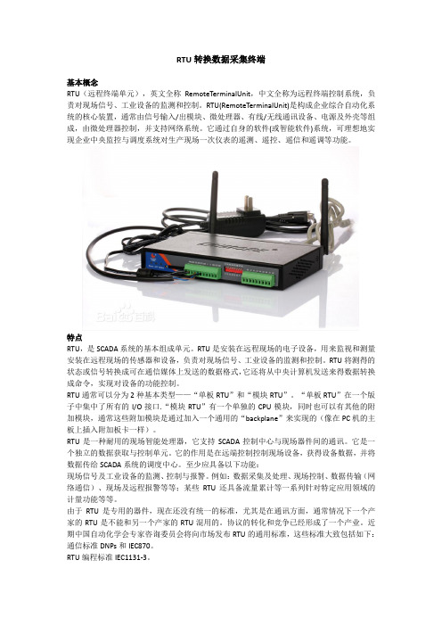
RTU转换数据采集终端基本概念RTU(远程终端单元),英文全称RemoteTerminalUnit,中文全称为远程终端控制系统,负责对现场信号、工业设备的监测和控制。
RTU(RemoteTerminalUnit)是构成企业综合自动化系统的核心装置,通常由信号输入/出模块、微处理器、有线/无线通讯设备、电源及外壳等组成,由微处理器控制,并支持网络系统。
它通过自身的软件(或智能软件)系统,可理想地实现企业中央监控与调度系统对生产现场一次仪表的遥测、遥控、遥信和遥调等功能。
特点RTU,是SCADA系统的基本组成单元。
RTU是安装在远程现场的电子设备,用来监视和测量安装在远程现场的传感器和设备,负责对现场信号、工业设备的监测和控制。
RTU将测得的状态或信号转换成可在通信媒体上发送的数据格式,它还将从中央计算机发送来得数据转换成命令,实现对设备的功能控制。
RTU通常可以分为2种基本类型——“单板RTU”和“模块RTU”。
“单板RTU”在一个版子中集中了所有的I/O接口.“模块RTU”有一个单独的CPU模块,同时也可以有其他的附加模块,通常这些附加模块是通过加入一个通用的“backplane”来实现的(像在PC机的主板上插入附加板卡一样)。
RTU是一种耐用的现场智能处理器,它支持SCADA控制中心与现场器件间的通讯。
它是一个独立的数据获取与控制单元。
它的作用是在远端控制控制现场设备,获得设备数据,并将数据传给SCADA系统的调度中心。
至少应具备以下功能:现场信号及工业设备的监测、控制与报警。
例如:数据采集及处理、现场控制、数据传输(网络通信)、现场及远程报警等等;某些RTU还具备流量累计等一系列针对特定应用领域的计量功能等等。
由于RTU是专用的器件,现在还没有统一的标准,尤其是在通讯方面,通常情况下一个产家的RTU是不能和另一个产家的RTU混用的。
协议的转化和竞争已经形成了一个产业。
近期中国自动化学会专家咨询委员会将向市场发布RTU的通用标准,这些标准大致包括如下:通信标准DNPs和IEC870。

RTU控制系统:安装与调试的全面指南1. 简介远程终端单元(Remote Terminal Unit,RTU)是一种用于监控和控制远程设备的电子设备。
它广泛应用于工业自动化、电力系统、交通运输等领域。
本指南将为您提供关于RTU控制系统的安装与调试的全面指导。
2. 准备工作在开始安装与调试RTU控制系统之前,请确保以下准备工作已完成:1. 熟悉RTU的规格书和技术文档,了解其功能、性能和接口要求。
2. 准备必要的安装工具和设备,如螺丝刀、扳手、万用表等。
3. 确保RTU的电源、通讯接口和传感器等配套设施已准备就绪。
4. 确定RTU的安装位置,确保其易于操作和维护。
3. RTU安装3.1 硬件安装1. 将RTU固定在合适的位置,确保其稳定可靠。
2. 连接电源线,根据电源要求选择合适的电源插头和电缆。
3. 连接通讯接口,如RS232、RS485、以太网等,使用相应的线缆和连接器。
4. 连接传感器和执行器,根据需要选择合适的信号类型和电缆。
3.2 软件安装1. 安装RTU配套的监控软件,根据厂家提供的安装说明进行操作。
2. 配置监控软件的基本参数,如通讯接口、采样率、报警阈值等。
3. 根据实际需求,配置附加功能,如数据存储、远程控制等。
4. RTU调试4.1 基本功能调试1. 检查RTU的电源电压和电流,确保其在正常范围内。
2. 测试RTU的通讯接口,如RS232、RS485、以太网等,确保与其他设备的通讯正常。
3. 检查RTU的传感器和执行器连接,确保信号传输稳定可靠。
4.2 监控软件调试1. 启动监控软件,检查与RTU的通讯连接是否正常。
2. 配置监控参数,如采样率、报警阈值等,确保其符合实际需求。
3. 观察监控软件的数据显示,检查数据的实时性、准确性和完整性。
4.3 系统集成与测试1. 将RTU控制系统与其他系统(如SCADA、PLC等)进行集成。
2. 进行系统测试,包括数据交换、指令下发、报警处理等。

RTU控制系统:安装与调试的全面指南1. 简介RTU(Remote Terminal Unit)控制系统是一种用于远程监测和控制的设备。
本文档旨在提供一份全面指南,帮助您安装和调试RTU控制系统。
2. 安装步骤以下是安装RTU控制系统的步骤:1. 选择合适的位置:选择一个适合安装RTU设备的位置,确保其能够稳定地工作并方便进行维护。
选择合适的位置:选择一个适合安装RTU设备的位置,确保其能够稳定地工作并方便进行维护。
2. 安装电源和通信线路:将RTU设备连接到电源,并根据需要连接通信线路(如以太网、串口等)。
安装电源和通信线路:将RTU设备连接到电源,并根据需要连接通信线路(如以太网、串口等)。
3. 安装传感器和执行器:根据实际需求,将传感器和执行器连接到RTU设备。
确保连接正确并稳固。
安装传感器和执行器:根据实际需求,将传感器和执行器连接到RTU设备。
确保连接正确并稳固。
4. 连接外部设备:如果需要与其他设备(如SCADA系统)进行通信,根据相应的接口和协议,将RTU设备连接到外部设备。
连接外部设备:如果需要与其他设备(如SCADA系统)进行通信,根据相应的接口和协议,将RTU设备连接到外部设备。
5. 进行电气连接:根据RTU设备的要求,进行电气连接,确保设备能够正常工作并符合安全标准。
进行电气连接:根据RTU设备的要求,进行电气连接,确保设备能够正常工作并符合安全标准。
3. 调试步骤以下是调试RTU控制系统的步骤:1. 检查硬件连接:仔细检查所有硬件连接,确保传感器、执行器和通信线路都正确连接并稳定。
检查硬件连接:仔细检查所有硬件连接,确保传感器、执行器和通信线路都正确连接并稳定。
2. 配置RTU参数:根据实际需求,配置RTU设备的参数,如通信协议、传感器类型、执行器控制方式等。
配置RTU参数:根据实际需求,配置RTU设备的参数,如通信协议、传感器类型、执行器控制方式等。
3. 测试传感器和执行器:使用合适的测试工具,对传感器和执行器进行测试,确保其正常工作并能够正确响应控制指令。
规格书基于OTDR 的远端测试单元RTU-2测试接入模块(TAM )套装可靠性高的1XN MEMS 光开关MPO 16纤芯连接器 有多个型号,分别配备32、64、128和256个端口体积小——仅有1/2U 高端口密度高:最高可达512个端口/1U 在支持高端口数的同时,其插损极低使用寿命超过25亿次 能耗极低PON/FTTx 机房内远程测试和监测大规模节点或边缘节点光纤测试和监测大纤芯数据中心互连和园区监测RTUe-9120外接光开关提供非常高的光开关端口密度,适用于基于OTDR 的远程光纤测试系统和光纤监测应用。
端口密度非常高的1XN MEMS 型光开关RTUe-9120如欲了解最新的专利标识标注信息,敬请访问/patent 。
EXFO 产品已获得ISO 9001认证,可确保产品质量。
EXFO 始终致力于确保本规格书中所包含的信息的准确性。
但是,对其中的任何错误或遗漏,我们不承担任何责任,而且我们保留随时更改设计、特性和产品的权利。
本文档中所使用的测量单位符合SI 标准与惯例。
此外,EXFO 制造的所有产品均符合欧盟的WEEE 指令。
有关详细信息,请访问/zh/corporate/social-responsibility 。
如需了解价格和供货情况,或查询当地EXFO 经销商的电话号码,请联系EXFO 。
如需获得最新版本的规格书,请访问EXFO 网站,网址为/specs 。
如打印文献与Web 版本存在出入,请以Web 版本为准。
扫描EXFO 二维码, 获取通信网络优化解决方案EXFO 公司总部 电话:+1 418 683-0211 免费电话:+1 800 663-3936(美国和加拿大)EXFO 中国 北京市海淀区中关村南大街12号天作国际中心写字楼1号楼A座第二十五层(邮编:100081) 电话:+86 10 89508858EXFO 为100多个国家的2000多家客户提供服务。
如欲了解当地分支机构联系详情,敬请访问/zh/contact 。
摘要电力远动终端RTU系统是电力调度自动化系统的核心部分,是计算机、数据信息通信、状态自动检测等技术相互协调配合形成的能够对电力供配电各环节进行实时监视和控制的综合智能操作系统。
在分析电力特性参数测量和计算方法的基础上,对电力远动终端RTU系统的拓扑结构进行详细的分析总结。
电力远动终端RTU大大提高电力系统自动化调度与管理水平,保障供配电系统高效稳定的运行。
本文首先对时下RTU的应用和现状展开了论述,使用TI公式的TMS320LF3407A芯片结合CAN总线设计出了符合要求的系统结构,使系统的响应速度更快,测量精度更准。
具有运算能力强,处理速度快以及工作可靠的特点。
最后文章采用C语言编程调试,结果进一步验证了高速、高精度、可靠的特点。
关键词:电网监控、远动终端RTU、DSPAbstractPower far move terminal RTU system is the core of the electric power dispatching automation system of, is a computer, data information communication, the state to be automatic detection technology to coordinate well with each other to form of power supply and distribution the links to real-time monitoring and control of comprehensive intelligence operation system. On the analysis of the characteristic parameters of electric power measure and calculation methods of the foundation, on the far end RTU system power move the topological structure of a detailed analysis of the summary. Power far move terminal RTU greatly improve the automation of electric power systems scheduling and management level, ensure the supply system for the operation of the high efficiency and stability.This paper first on the current application and current situation of RTU on this paper, and use of the formula TMS320LF3407A with TI chips CAN bus designed to meet the requirements of system structure, make the system response speed faster and more accurate measurement accuracy. Has the operation ability, processing speed and reliable characteristic. At last this paper adopts the C programming language testing, the results further verified high speed and high precision and reliable.Keywords: grid monitoring, far move terminal RTU, DSP目录第一章绪论 (3)1.1 国内外RTU发展现状 (3)1.1.1 国外RTU的发展现状 (3)1.1.2 国内RTU的发展现状 (3)1.2论文主要内容 (5)第二章RTU系统方案的构建 (6)2.1电力参数的测量 (6)2.1.1交流电参量的采样方法 (6)2.1.2采样点数的选择 (7)2.1.3基于快速傅立叶变换FFT的电量测量原理 (8)2.1.4频率的测量 (9)2.1.5电流、电压的测量 (9)2.1.6电功率、功率因数的测量 (10)2.2 RTU的基本功能 (11)2.3 微处理器的选择 (12)2.3.1数字信号处理器的主要特点 (12)2.3.2 DSP芯片的选取 (13)2.3.3锁相环同步及频率采样电路 (13)2.4通信方式的实现 (14)2.5系统的总体方案 (15)第三章 RTU系统的硬件电路设计 (17)3.1 信号测量模块的电路设计 (17)3.1.1电压和电流采集电路 (18)3.1.2锁相环同步及频率采样电路 (20)3.1.3开关量与脉冲量的采集 (21)3.2 通信主控模块的电路设计 (22)3.2.1 CAN接口电路 (23)3.2.2串行通信接口电路 (24)3.2.3显示和键盘接口电路 (25)3.2.4 LF2407A的EEPROM扩展及SRAM电路的设计 (26)第四章RTU系统的软件设计 (28)4.1系统软件的总体设计思想 (28)4.2信号测量模块的软件设计 (28)4.2.1 A/D转换子程序的设计 (30)4.2.2 频率测量程序的设计 (30)4.3通信主控模块的软件设计 (31)4.3.1 CAN接口子程序的设计 (32)4.3.2人机接口子程序的设计 (34)4.4数据测试结果与分析 (35)第五章结论 (37)致谢 (38)参考文献 (39)第1章绪论1.1国内外RTU的发展与现状1.1.1国外RTU的发展现状对于变电站自动化监控系统,很多国家都做了大量的研究工作,目前各在电网计机监控系统方面多采用分层分布开放式系统结构,该系统是把电厂的各项功能,按分层分布处理的原则由功能模块和接口模块组成计算机分布系统,整个系统统一协调,合理分工,最佳运行管理。
User ManualVersion 1.1 Feb 2021ACS-20B(W)-MRTU No-touch Infrared Sensor SwitchWritten by Bruce HsuEdited by Kalia HuangTable of Contents1.Introduction (6)1.1Features (7)2.Hardware (8)2.1Specifications (8)2.2Appearance (9)2.3Pin assignments (10)2.4LED Indicators (11)3.Configured by Hardware (12)3.1Relay Hold Time (12)3.2Toggle Switch Mode (13)3.3Sensing Range (13)3.4Restore Default Communication Settings (14)4.Configured by Software (15)4.1ACS-20 Utility (15)4.2Serial Communication (16)4.3Test Locked Mode (17)4.4Set Relay Hold Time (17)4.5Set Toggle Mode (18)4.6Invert Red/Blue LED (18)4.7Set RTC (19)4.8Set IR Sensing Record Mode (20)4.9Set Locked Periods (20)4.10Access All Settings (21)4.11Configuration File (22)5.Modbus Command (23)5.1Modbus Register Table (24)5.1.1Modbus Input Registers (24)5.1.2Modbus Holding Registers (25)5.2Modbus FC100 Commands (26)5.2.1Sub-FC00 (0x00): Get the Module Name (27)5.2.2Sub-FC04 (0x04): Set the Modbus Unit ID (Net ID) (28)5.2.3Sub-FC05 (0x05): Get Communication Settings (29)5.2.4Sub-FC06 (0x06): Set Communication Settings (30)5.2.5Sub-FC07 (0x07): Read Current Communication Settings (31)5.2.6Sub-FC08 (0x08): Get Modbus Response Delay (32)5.2.7Sub-FC09 (0x09): Set Modbus Response Delay (33)5.2.8Sub-FC32 (0x20): Get Firmware Version (34)5.2.9Sub-FC33 (0x21): Get Firmware Date (35)5.2.10Sub-FC34 (0x22): Get Stored Quantity of IR Sensing Records (36)5.2.11Sub-FC35 (0x23): Clear All Stored IR Sensing Records (37)5.2.12Sub-FC39 (0x27): Get RTC Time (38)5.2.13Sub-FC40(0x28): Set RTC Time (39)5.2.14Sub-FC41(0x29): Get IR Sensing Record Data (40)5.2.15Sub-FC42(0x2A): Get IR Sensing Record Mode (41)5.2.16Sub-FC43(0x2B): Set IR Sensing Record Mode (42)5.2.17Sub-FC44(0x2C): Get Inverted Red/Blue LED Status (43)5.2.18Sub-FC45(0x2D): Set Inverted Red/Blue LED Status (44)5.2.19Sub-FC46(0x2E): Get Relay Hold Time (45)5.2.20Sub-FC47(0x2F): Set Relay Hold Time (46)5.2.21Sub-FC64(0x40): Get Locked Mode (47)5.2.22Sub-FC65(0x41): Set Locked Mode (48)5.2.23Sub-FC66(0x42): Get Day Mode of Locked Periods (49)5.2.24Sub-FC67(0x43): Set Day Mode of Locked Periods (50)5.2.25Sub-FC68(0x44): Get Enabled State of Locked Periods (51)5.2.26Sub-FC69(0x45): Set Enabled State of Locked Periods (52)5.2.27Sub-FC70(0x46): Get 8 Locked Periods (53)5.2.28Sub-FC71(0x47): Set 8 Locked Periods (54)5.2.29Sub-FC72(0x48): Get Enabled State of Locked Period Function (55)5.2.30Sub-FC73(0x49): Set Enabled State of Locked Period Function (56)5.2.31Sub-FC76(0x4C): Get Scale Value of Rotary Switch (57)5.2.32Sub-FC77(0x4D): Get Toggle Mode (58)5.2.33Sub-FC78(0x4E): Set Toggle Mode (59)5.2.34Sub-FC165(0xA5): Reboot Module (60)Appendix A. Update Firmware (61)Appendix B. Revision History (63)Important InformationWarrantyAll products manufactured by ICP DAS are under warranty regarding defective materials for a period of one year, beginning from the date of delivery to the original purchaser.WarningICP DAS assumes no liability for any damage resulting from the use of this product.ICP DAS reserves the right to change this manual at any time without notice. The information furnished by ICP DAS is believed to be accurate and reliable. However, no responsibility is assumed by ICP DAS for its use, not for any infringements of patents or other rights of third parties resulting from its use.CopyrightCopyright @ 2021 by ICP DAS Co., Ltd. All rights are reserved.TrademarkNames are used for identification purpose only and may be registered trademarks of their respective companies.Contact us1. IntroductionFigure 1-1 ACS-20B(W)-MRTU application architecture The No-touch Infrared Sensor Switch from ICP DAS can be used to open a door using palm induction, which makes it more convenient when entering or exiting a room or building. The inductive distance and the delay time for door opening are adjustable, and has red and blue indicator lights to show the status of the switch. As people enter and exit the door using the No-touch Infrared Sensor Switches, a time stamp recording the action can be simultaneously logged.The No-touch Infrared Sensor Switch includes an RS-485 interface and provides Modbus RTU communication, which can remotely enable/disable the switch and get the induction time records by the access control system.Additionally, the No-touch Infrared Sensor Switch is not only used for the access control system but also helps you control other electronic devices. While it is triggered in toggle mode at the first time, the switch outputs ON signal, and next time outputs OFF signal.The No-touch Infrared Sensor Switch can be used with electric doors to prevent issues related to the spread of infectious bacteria via touch. The switches can be used in medical institutions, retail stores, the food industry, industrial plants, and offices, etc. to provide an excellent sanitary environment.1.1 Features◼[ACS-20B-MRTU / ACS-20W-MRTU]◆Special infrared code to against interference◆Multiple operating modes: Sensing/Standby, Lock, Toggle Switch.◆Provides 8 locked periods each day◆Double-color status indicator◆Induction distance: 1 ~ 12 cm◆With Relay (N.C. and N.O. output)◆Relay hold time: 0.5 ~ 20 sec◆The switches time recording: 1,600 records◆Communication interface and protocol: RS-485/Modbus RTU◼[Applications]◆ Surveillance system◆ Home and building automation◆Medical institutions◆Retail stores◆Food industry2. Hardware2.1 SpecificationsTable 2-1: Specification Table2.2 AppearanceFigure 2-1: ACS-20B-MRTU.Figure 2-2: ACS-20W-MRTU2.3 Pin assignments◼TerminalsFigure 2-3: ACS-20B(W)-MRTU terminals◼CablesTable 2-2: Cables for ACS-20B(W)-MRTU terminalCablesPicture Model. Description InterfaceCA-014+Vs (Red)(+10~+30VDC)Power GND (Black)-CA-012NO (Blue)Relay COM (White)NC (Green)CA-019DATA+(Green)RS-485 DATA- (黃)2.4 LED IndicatorsThere are circular red and blue led indicators on the ACS-20B/W-MRTU to show different operating states. The meanings of these states are described in Table 2-3.Figure 2-4: Red/Blue LED indicators of ACS-20B(W)-MRTUTable 2-3: Red/Blue LED indicators corresponding to module status LED Circular LED Indicator ACS-20B(W)-MRTU StatusRed Blue Red LED ON (NC & COM contacted) (*)Standby; Toggle mode (ON) Blue LED ON (NO & COM contacted) (*)IR sensing; Toggle mode (OFF) Red LED blinks once per 2 seconds Locked modeRed & blue LED blink 2 times per second Firmware update mode* The module status inverted if red and blue LEDs are inverted.3. Configured by Hardware3.1 Relay Hold TimeRelay hold time (off-delay time) after IR sensing can be set by the scale position “0~C” of the rotary switch (figure 3-1) as shown in table 3-1.Figure 3-1: Scale 0~C of rotary switch for relay hold timeTable 3-1: relay hold time to the scale of the rotary switchscale Relay hold time (sec)0 0.51 12 23 34 45 56 67 78 89 9A 10B 15C 203.2 Toggle Switch ModeRotate the rotary switch to the scale ‘D’ to be in the hardware Toggle Switch Mode. In this mode, sense the ACS-20B(W)-MRTU by hand once, the circular red LED is changed to blue (Relay: NO & COM contact). Then, sense the ACS-20B(W)-MRTU by hand once again, the blue LED will be changed back to red. (Relay: NC & COM contact)Figure 3-2: Scale 0~C of rotary switch for relay hold time3.3 Sensing RangeSensing range (sensed by palm of the hand) of ACS-20B(M)-MRTU can be adjusted by the rotary knob in figure 3-3. Rotate the knob clockwise to extend the sensing range (maximum 12 cm). Rotate the knob counterclockwise to reduce the sensing range (minimum 1 cm around). The scale is not linear between minimum and maximum limit. The default scale is rotated clockwise to the maximum limit.Figure 3-3: Rotary knob for sensing range (sensed by palm)3.4 Restore Default Communication SettingsRotate the rotary switch to the scale ‘E’. Power cycle the module to restore the default serial communication (Table ).Figure 3-4: Rot ate the rotary switch to ‘E’ scale for default communication.Table 3-2: relay hold time to the scale of the rotary sItem Default valueBaud Rate 9600 bpsParitys NoneData Bits 8Stop Bits 1Modbus Response Delay 1 msModbus Net ID 14. Configured by Software4.1 ACS-20 UtilityACS-20 Utility is the configuration tool for ACS-20B(W)-MRTU. It runs in .NET Framework 4.5 based on Microsoft Windows OS. Users can download the ACS-20 Utility from:ACS-20 Utility (ACS20_Util_Setup_v#i#i#i#.zip)https:///en/download/show.php?num=3154&model=ACS-20B-MRTUIf the .NET Framework 4.5 is not available on the Microsoft OS, the setup package will download and install the redistribution automatically. The redistribution package can also be downloaded from the following link:https:///en-US/download/details.aspx?id=306534.2 Serial CommunicationThe initial window of the ACS-20 utility is shown in the left of figure 4-1. Select the COM port of the host PC and the communication parameters of ACS-20B(W)-MRTU. Go to the main configuration window by clicking the “Connect” button.Figure 4-1: Configuration window for ACS-20B(W)-MRTU.I f the main configuration window is opened by the “Open Interface” button, click menu [Connect]=>[Connect ACS-20-MRTU] to open the connection window as shown in figure 4-2.Figure 4-2: Connection window for the main configuration window.S et the communication parameters by clicking the “Set” button in the Communication Settings section in figure 4-3. Refer to chapter 5 for related Modbus command.Figure 4-3: Set communication settings.4.3 Test Locked ModeIn the “IR Sensing” section of the utility, click “Lock” and “Unlock” button (figure 4-4) to test the locked mode. IR sensing function is disabled in this mode. Refer to chapter 5 for related Modbus command.Figure 4-4: T est locked mode.4.4 Set Relay Hold TimeIn the “IR Sensing” section of the utility, there are “0.5 ~ 20 sec” items in the “Relay Hold Time” combobox (figure 4-5) for selection. Click the “Set” button to set the paramter. Refer to chapter 5 for related Modbus register and command.Figure 4-5: Set relay hold time.4.5 Set Toggle ModeIn the “IR Sensing” section of the utility, click the “Set” button after checking or unchecking the “Toggle Mode” checkbox as shown in figure 4-6. Refer to chapter 5 for related Modbus register and command.Figure 4-6: Set toggle mode.4.6 Invert Red/Blue LEDIn the “IR Sensing” section of the utility, click the “Set” button after checking or unchecking the “Invert Red/Blue LED” checkbox as shown in figure 4-7. Refer to chapter 5 for related Modbus register and command.Figure 4-7: Set inversion of Red/Blue LED.4.7 Set RTCThere is built-in RTC (Real Time Clock) in ACS-20B(W)-MRTU. One RTC Time (Year/Month/Day, Hour:Minute:Second) is recorded when IR sensing by palm of hand.I n the “Set RTC” section(figure 4-8) of the utility, the time following the “System Time” radio button is the host system time. Customize the t ime by clicking the “Custom Time” radio button. Click the “Set” button to set RTC with the tiime folowing the selected radio button. Refer to chapter 5 for the related Modbus command to access RTC.Figure 4-8: Set RTC4.8 Set IR Sensing Record ModeThe “Record Mode” in the “IR Sensing Records in Storage ” section (figure 4-9) is for setting the storage mode when the storage is full. There are two modes:Mode 0 (Store from start): (default) Clear all records and store from start. Mode 1 (Discard the latest): Discard new data and keep 1600 records of old data.Figure 4-9: Set IR sensing record mode.4.9 Set Locked PeriodsLocked periods can be set in the “Locked Periods Settings” section of the utility as shown in figure 4-10. The module goes into locked mode (no IR sensing) in the locked period.Figure 4-10: Set locked periods.◆♦⌧⍓(1) Check/Uncheck “Enabled Locked Periods Function” checkbox to enable/disable thisfunction.(2) C lick the “Locked Periods” combobox to select 8 periods (0 ~ 7) for setting. The “EndTime” should be more than the “Start Time”.(3) C lick “Enable Every Day Mode” or “Enable Week Day Mode” radio button for “Every DayMode” or “Week Day Mode”.(4) This combobox can set the locked periods for every day and weekdays (Sunday toSaturday) by checking or unchecking the P0 ~ P7 checkboxes to enable or disable them.(5) Click the righ t “Set” button to finish the setting.4.10 Access All SettingsSeparate settings can be set as previous sections. Or click Menu [Settings]=>[Download All Settings to the ACS-20-MRTU] to set all settings to the module at once after all parameters are selected in the utility.Click Menu [Settings]=>[Load All Settings from the ACS-20-MRTU] to read back all settings to utility from the module at once.Figure 4-11: Access all setting of the module.4.11 Configuration FileAll settings in the utility can be saved to a configuration file by clicking Menu [File]=>[Save Settings to File(*.dat)] where the file extension is dat.Load all setting from a configuration file by clicking Menu [File]=>[Load Settings from File(*.dat)]Figure 4-12: Access configuration file.5. Modbus CommandThe following Function Code commands () are provided for a Modbus master to configure ACS-20B(W)-MRTU. FC3, FC4, and FC6 are the standard Modbus commands for Modbus masters to access the Modbus registers. Sub-FC commands of FC100 are manufacturer assigned commands for parameter settings on the module.Table 5-1: Modbus Function Code for ACS-20B(W)-MRTU5.1 Modbus Register TablePlease refer to table 5-2 and table 5-3 for the Modbus Input Registers (3xxxx) and Modbus Holding Registers (4xxxx). Settings written to the Modbus holding registers are all volatile for ACS-20B(W)-MRTU. The values will go back to the default or previous ones after power cycling. The settings can be kept (non-volatile) by the FC100 commands in section 5.2.5.1.1 Modbus Input RegistersThe Modbus Input Registers are listed in Table 5-2. They are read-only registers.Table 5-2: Modbus Input Registers (3xxxx)5.1.2 Modbus Holding RegistersThe Modbus Holding Registers are listed in Table 5-3. The access is read and write. Write values to the holding registers can change settings immediately but restore to previous ones after power cycling the module.Table 5-3: Modbus Holding Registers (4xxxx)5.2 Modbus FC100 CommandsThis section describes all sub function calls (sub-FC) of FC100 (0x64) for the settings on ACS-20B(W)-MRTU. All sub-FCs are listed in table 5-4. All setting values are non-volatile (effective after power-cycling the module). In the following sections, Modbus requests and responses are listed without CRC16 bytes.Table 5-4: Sub-FCs of FC1005.2.1 Sub-FC00 (0x00): Get the Module NameThe request/response for getting the module name is listed in table 5-5 and table 5-6.Table 5-5: FC100-Sub-FC00 RequestTable 5-6: FC100-Sub-FC00 Response5.2.2 Sub-FC04 (0x04): Set the Modbus Unit ID (Net ID)Table 5-7: FC100-Sub-FC04 RequestTable 5-8: FC100-Sub-FC04 ResponseNote: This parameter setting is effective after power cycling the module,5.2.3 Sub-FC05 (0x05): Get Communication SettingsTable 5-9: FC100-Sub-FC05 RequestTable 5-10: FC100-Sub-FC05 Response5.2.4 Sub-FC06 (0x06): Set Communication SettingsTable 5-11: FC100-Sub-FC06 RequestTable 5-12: FC100-Sub-FC06 Response5.2.5 Sub-FC07 (0x07): Read Current Communication SettingsThe settings read from Sub-FC05 is the settings by Sub-FC06 if the Byte 09 [Change Setting] of Sub-FC06 is 0 (The settings are effective after power-cycling). Sun-FC07 reads the settings before power-cycling the module.Table 5-13: FC100-Sub-FC07 RequestTable 5-14: FC100-Sub-FC07 Response5.2.6 Sub-FC08 (0x08): Get Modbus Response DelayTable 5-15: FC100-Sub-FC08 RequestTable 5-16: FC100-Sub-FC08 Response5.2.7 Sub-FC09 (0x09): Set Modbus Response DelayTable 5-17: FC100-Sub-FC09 RequestTable 5-18: FC100-Sub-FC09 Response5.2.8 Sub-FC32 (0x20): Get Firmware VersionTable 5-19: FC100-Sub-FC32 RequestTable 5-20: FC100-Sub-FC32 Response5.2.9 Sub-FC33 (0x21): Get Firmware DateTable 5-21: FC100-Sub-FC33 RequestTable 5-22: FC100-Sub-FC33 Response5.2.10 Sub-FC34 (0x22): Get Stored Quantity of IR Sensing RecordsTable 5-23: FC100-Sub-FC34 RequestTable 5-24: FC100-Sub-FC34 Response5.2.11 Sub-FC35 (0x23): Clear All Stored IR Sensing RecordsTable 5-25: FC100-Sub-FC35 RequestTable 5-26: FC100-Sub-FC35 Response5.2.12 Sub-FC39 (0x27): Get RTC TimeTable 5-27: FC100-Sub-FC39 RequestTable 5-28: FC100-Sub-FC39 Response5.2.13 Sub-FC40(0x28): Set RTC TimeTable 5-29: FC100-Sub-FC40 RequestTable 5-30: FC100-Sub-FC40 Response5.2.14 Sub-FC41(0x29): Get IR Sensing Record DataTable 5-31: FC100-Sub-FC41 RequestTable 5-32: FC100-Sub-FC41 ResponseNote: Data length of 1 record is 8 bytes([Year_MSB][Year_LSB][Month][Day][Hour][Minute][Second])5.2.15 Sub-FC42(0x2A): Get IR Sensing Record ModeTable 5-33: FC100-Sub-FC42 RequestTable 5-34: FC100-Sub-FC42 Response5.2.16 Sub-FC43(0x2B): Set IR Sensing Record ModeTable 5-35: FC100-Sub-FC43 RequestTable 5-36: FC100-Sub-FC43 Response5.2.17 Sub-FC44(0x2C): Get Inverted Red/Blue LED StatusTable 5-37: FC100-Sub-FC44 RequestTable 5-38: FC100-Sub-FC44 Response5.2.18 Sub-FC45(0x2D): Set Inverted Red/Blue LED StatusTable 5-39: FC100-Sub-FC45 RequestTable 5-40: FC100-Sub-FC45 Response5.2.19 Sub-FC46(0x2E): Get Relay Hold TimeTable 5-41: FC100-Sub-FC46 RequestTable 5-42: FC100-Sub-FC46 Response5.2.20 Sub-FC47(0x2F): Set Relay Hold TimeTable 5-43: FC100-Sub-FC47 RequestTable 5-44: FC100-Sub-FC47 Response5.2.21 Sub-FC64(0x40): Get Locked ModeTable 5-45: FC100-Sub-FC64 RequestTable 5-46: FC100-Sub-FC64 Response5.2.22 Sub-FC65(0x41): Set Locked ModeTable 5-47: FC100-Sub-FC65 RequestTable 5-48: FC100-Sub-FC65 Response5.2.23 Sub-FC66(0x42): Get Day Mode of Locked PeriodsTable 5-49: FC100-Sub-FC66 RequestTable 5-50: FC100-Sub-FC66 Response5.2.24 Sub-FC67(0x43): Set Day Mode of Locked PeriodsTable 5-51: FC100-Sub-FC67 RequestTable 5-52: FC100-Sub-FC67 Response。