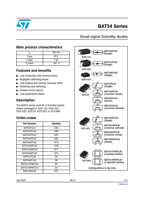
BAT54CWPBF资料
- 格式:pdf
- 大小:79.96 KB
- 文档页数:5
Document Number: 94270For technical questions, contact: diodes-tech@vishay.comwww.vishay.comRevision: 19-Sep-081Schottky Diode, 2 x 0.1 ABAT54CWPbFVishay High Power Products
FEATURES•Small foot print, surface mountable•Very low forward voltage drop•Extremely fast switching speed for highfrequency operation•Guard ring for enhanced ruggedness and long termreliability•Lead (Pb)-free•Designed and qualified for industrial levelDESCRIPTIONThis Schottky barrier diode is designed for high speedswitching applications, voltage clamping and circuitprotection. Miniature surface mount packages with reducedfoot print are excellent for portable applications where spaceis limited.PRODUCT SUMMARYIF(AV)2 x 0.1 AVR30 V
SOT-323213(K)
(A)(A)AvailablePb-freeRoHS*COMPLIANTMAJOR RATINGS AND CHARACTERISTICSSYMBOLCHARACTERISTICSVALUESUNITSIFDC0.2AVRRM30VIFSMtp = 10 ms sine1.0AVF30 mA DC, TJ = 25 °C 0.5VPdPower dissipation at TA = 25 °C200mWTJRange- 65 to 150°CVOLTAGE RATINGSPARAMETERSYMBOLBAT54CWPbFUNITSMaximum DC reverse voltageVR30VMaximum working peak reverse voltageVRWMABSOLUE MAXIMUM RATINGSPARAMETER S
YMBOLTES
T CONDITIONS
VALUES
UNITS
Maximum averageforward currentper legIF(AV)DC0.1Aper device0.2Maximum peak one cyclenon-repetitive surge currentat TJ = 25 °CIFSM5 µs sine or 3 µs rect. pulseFollowing any rated load condition and with rated VRRM applied8.410 ms sine or 6 ms rect. pulse1.0
* Pb containing terminations are not RoHS compliant, exemptions may apply元器件交易网www.cecb2b.com www.vishay.comFor technical questions, contact: diodes-tech@vishay.comDocument Number: 942702
Revision: 19-Sep-08BAT54CWPbFVishay High Power ProductsSchottky Diode, 2 x 0.1 A
Note(1)Pulse width < 300 µs, duty cycle < 2 %
Note(1) thermal runaway condition for a diode on its own heatsinkELECTRICAL SPECIFICATIONSPARAMETER
SYMBOLTE
ST CONDITION
SVALUE
SUNIT
SMaximum forward voltage drop VFM (1)0.1 A
TJ = 25 °C0.65V30 mA0.5010 mA0.401 mA0.320.1 mA0.24Maximum reverse leakage current IRM (1)VR = 25 V2µAVR = 30 V3Maximum junction capacitance CTVR = 1 VDC (test signal range 100 kHz to 1 MHz),TJ = 25 °C10pFMaximum voltage rate of change dV/dtRated VR10 000V/µs
THERMAL - MECHANICAL SPECIFICATIONSPARAMETERSYMBOLTEST CONDITIONSVALUESUNITSMaximum junction and storagetemperature rangeTJ (1), TStg- 65 to 150°CMaximum thermal resistance, junction to ambientRthJAMounted on PC board FR4 with minimum pad size625°C/WApproximate weight0.006gMarking deviceCase style SOT-323KYWLCdPtotdTJ-------------1RthJA--------------
3BAT54CWPbFSchottky Diode, 2 x 0.1 AVishay High Power Products
Fig. 1 - Maximum Forward Voltage Drop Characteristics (Per Leg)
Fig. 2 - Typical Values of Reverse Current vs. Reverse Voltage (Per Leg)Fig. 3 - Typical Junction Capacitance vs. Reverse Voltage (Per Leg)
Fig. 4 - Forward Power Loss Characteristics
Fig. 5 - Maximum Non-Repetitive Surge Current0.00010.10.010.0011
IF - Instantaneous
Forward Current (A)
VFM - Forward Voltage Drop (V)0.20.40.60.81.00TJ = 150 °CTJ = 125 °CTJ = 25 °C
0.000010.010.1
0.0010.00011
IR - Reverse Current (mA)
VR - Reverse Voltage (V)105152030250TJ = 150 °CTJ = 125 °CTJ = 100 °CTJ = 75 °CTJ = 50 °CTJ = 25 °C110
CT - Junction Capacitance (pF)
VR - Reverse Voltage (V)105152025300TJ = 25 °C
00.30.20.10.4
Average Power Loss (W)
IF(AV) - Average Forward Current (A)0.30.10.20RMS limit
D = 0.20D = 0.25D = 0.33D = 0.50D = 0.75DC
0.1110
IFSM - Non-Repetitive Surge Current (A)
tp - Square Wave Pulse Duration (µs)100100010 00010At any rated load conditionand with rated VRRM appliedfollowing surge元器件交易网www.cecb2b.com www.vishay.comFor technical questions, contact: diodes-tech@vishay.comDocument Number: 942704
Revision: 19-Sep-08BAT54CWPbFVishay High Power ProductsSchottky Diode, 2 x 0.1 A ORDERING INFORMATION TABLEDEVICEPACKAGEMARKINGCONFIGURATIONBASE QUANTITYDELIVERY MODEBAT54CWSOT-323KYWLCDual common cathode3000Tape and reelLINKS TO RELATED DOCUMENTSDimensionshttp://www.vishay.com/doc?95050Part marking informationhttp://www.vishay.com/doc?95338Packaging informationhttp://www.vishay.com/doc?95061元器件交易网www.cecb2b.com Document Number: 91000 www.vishay.comRevision: 18-Jul-081DisclaimerLegal Disclaimer NoticeVishay
All product specifications and data are subject to change without notice. Vishay Intertechnology, Inc., its affiliates, agents, and employees, and all persons acting on its or their behalf(collectively, “Vishay”), disclaim any and all liability for any errors, inaccuracies or incompleteness contained hereinor in any other disclosure relating to any product. Vishay disclaims any and all liability arising out of the use or application of any product described herein or of anyinformation provided herein to the maximum extent permitted by law. The product specifications do not expand orotherwise modify Vishay’s terms and conditions of purchase, including but not limited to the warranty expressedtherein, which apply to these products. No license, express or implied, by estoppel or otherwise, to any intellectual property rights is granted by thisdocument or by any conduct of Vishay. The products shown herein are not designed for use in medical, life-saving, or life-sustaining applications unlessotherwise expressly indicated. Customers using or selling Vishay products not expressly indicated for use in suchapplications do so entirely at their own risk and agree to fully indemnify Vishay for any damages arising or resultingfrom such use or sale. Please contact authorized Vishay personnel to obtain written terms and conditions regardingproducts designed for such applications. Product names and markings noted herein may be trademarks of their respective owners.元器件交易网www.cecb2b.com