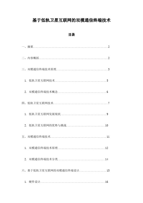
ST-AC005 6G天线耦合板
- 格式:pdf
- 大小:484.08 KB
- 文档页数:2

NB天线的基础知识目录一、NB天线概述 (2)1.1 NB天线定义 (2)1.2 NB天线分类 (3)1.2.1 根据工作频段分类 (4)1.2.2 根据结构形式分类 (6)1.3 NB天线的应用场景 (7)二、NB天线的工作原理 (8)2.1 电磁波的传播 (9)2.2 天线的工作原理 (10)2.3 NB天线的辐射特性 (11)三、NB天线的性能参数 (13)四、NB天线的设计与发展趋势 (14)4.1 NB天线设计原则 (15)4.2 新型NB天线技术 (17)4.3 NB天线的发展趋势 (18)五、NB天线与整机的集成与优化 (19)5.1 整机天线集成方式 (20)5.2 天线与整机的兼容性 (22)5.3 天线优化方法 (23)六、NB天线仿真与测试 (24)6.1 仿真在NB天线设计中的应用 (26)6.2 测试设备与方法 (27)6.3 仿真与测试结果分析 (28)一、NB天线概述NB天线,即窄带天线,是一种在无线通信领域中广泛应用的电磁辐射与接收器件。
其主要作用是将高频电流转换为电磁波并辐射出去,或者接收特定频率的电磁波并将其转换为电流信号。
NB天线是无线通信系统中不可或缺的一部分,其性能直接影响到整个通信系统的质量和效率。
NB天线具有一些显著的特点,如结构简单、易于制造、成本低廉等。
其设计通常考虑到特定的应用需求,如天线的大小、形状、频带宽度等,都需要根据实际应用场景进行优化。
NB天线广泛应用于移动通信基站、卫星通信、无线局域网、物联网等领域。
随着无线通信技术的高速发展,NB天线在日常生活和工作中的应用越来越广泛。
从手机到平板电脑,从无线路由器到通信基站,甚至在很多智能设备和系统中,都可以看到NB天线的身影。
对NB天线的基础知识进行了解和掌握,对于从事无线通信领域的工作者来说,是非常必要的。
1.1 NB天线定义NB天线,即窄带物联网(Narrowband Internet of Things)天线,是一种专门用于窄带物联网通信的无线通信天线。

Quick Start GuideSWRU425–December2015 Dual-Mode Bluetooth®CC2564Module With IntegratedAntenna Evaluation BoardThis quick-start guide offers an overview of the CC2564MODAEM evaluation board for the dual-mode Bluetooth CC2564module with integrated antenna(CC2564MODA),including required hardware and software tools and basic settings.For more information,see the Dual-Mode Bluetooth CC2564Module With Integrated Antenna Evaluation Board User Guide(SWRU427).Contents1Introduction (2)2CC2564MODAEM Kit Contents (2)3CC2564MODAEM Requirements (3)4CC2564MODAEM Board Overview (4)5CC2564MODAEM Board Settings (5)List of Figures1CC2564MODAEM Board (2)2Hardware Setup Examples (3)3CC2564MODAEM Front View (4)4CC2564MODAEM Back View (4)List of Tables1EM1Standard Pinout (5)2EM2Standard Pinout (5)3COM Connector Pinout (6)1 SWRU425–December2015Dual-Mode Bluetooth®CC2564Module With Integrated Antenna EvaluationBoard Submit Documentation FeedbackCopyright©2015,Texas Instruments IncorporatedIntroduction 1IntroductionThe CC2564MODAEM board is used to evaluate the TI CC2564MODA device,which supports classicBluetooth and Bluetooth low energy(LE)wireless technology.The CC2564MODAEM works with TI'shardware development kits(HDKs),such as the following:•MSP-EXP430F5529•MSP-EXP430F5438•DK-TM4C123G•DK-TM4C129XThe CC2564MODA device is a complete basic rate(BR),enhanced data rate(EDR),and LE hostcontroller interface(HCI)solution that reduces design effort and enables fast time to market.Based on TI’s seventh-generation core,the module brings a product-proven solution supporting Bluetooth4.1dual-mode protocols.Figure1shows the CC2564MODAEM board.2564MODAEM Board2CC2564MODAEM Kit ContentsThe CC2564MODAEM kit contains the following contents:•One CC2564MODAEM board,including the dual-mode Bluetooth CC2564module with integrated antenna•One block jumper for the MSP-EXP430F5438board•Four jumpers for the MSP-EXP430F5529board2Dual-Mode Bluetooth®CC2564Module With Integrated Antenna Evaluation SWRU425–December2015 Board Submit Documentation FeedbackCopyright©2015,Texas Instruments Incorporated CC2564MODAEM Requirements 3CC2564MODAEM RequirementsFor a complete evaluation,the CC2564MODAEM board requires hardware and software tools selected from the following list:•HardwareMSP430™experimenter board(sold separately)or TM4C development kit(sold separately):–MSP430experimenter board options•MSP-EXP430F5529•MSP-EXP430F5438–TM4C development kit options•DK-TM4C123G•DK-TM4C129X•Software•TI dual-mode Bluetooth stack•On MSP430MCUs:CC256XMSPBTBLESW•On TM4C MCUs:CC256XM4BTBLESW•Other MCUs•On STM32F4MCUs:CC256XSTBTBLESWFigure2shows example hardware setups for the CC2564MODAEM board using the MSP-EXP430F5529 and MSP-EXP430F5438experimenter boards.Figure2.Hardware Setup Examples3 SWRU425–December2015Dual-Mode Bluetooth®CC2564Module With Integrated Antenna EvaluationBoard Submit Documentation FeedbackCopyright©2015,Texas Instruments IncorporatedCC2564MODAEM Board Overview 4CC2564MODAEM Board OverviewThe CC2564MODAEM board has two different connectors:•EM(default):I/Os are at3.3V.•COM:I/Os are at1.8V.Figure3shows the connectors on the front side of the CC2564MODAEM board.2564MODAEM Front ViewFigure4shows the connectors on the back side of the CC2564MODAEM board.2564MODAEM Back View4Dual-Mode Bluetooth®CC2564Module With Integrated Antenna Evaluation SWRU425–December2015 Board Submit Documentation FeedbackCopyright©2015,Texas Instruments Incorporated CC2564MODAEM Board Settings 5CC2564MODAEM Board SettingsThis section describes the settings for the EM connector and the COM connector.5.1EM Connector SettingsThe EM connectors can be mounted on a wide variety of TI MCU platforms,such as the MSP430(MSP-EXP430F5529and MSP-EXP430F5438)and TM4C(DK-TM4C123G and DK-TM4C129X).All EM I/Os are at3.3-V levels.Pin assignments are described with respect to the front(CC2564MODA) side.For example,MODULE_UART_RX refers to the receiving UART RX pin on the CC2564MODAdevice that connects to the UART_TX pin on the MCU.Table1describes the standard pinout for EM1.Table1.EM1Standard PinoutPin EM Adapter Assignment(1)Pin EM Adapter Assignment(1)1GND2NC3MODULE_UART_CTS4NC5SLOW_CLK6NC7MODULE_UART_RX8NC9MODULE_UART_TX10NC11NC12NC13NC14NC15NC16NC17NC18NC19GND20NC(1)NC=not connectedTable2describes the standard pinout for EM2.Table2.EM2Standard PinoutPin EM Adapter Assignment(1)Pin EM Adapter Assignment(1)1NC2GND3NC4NC5NC6NC7 3.3V8MODULE_AUDIO_DATA_OUT9 3.3V10MODULE_AUDIO_DATA_IN11MODULE_AUDIO_FSINK12NC13NC14NC15NC16NC17MODULE_AUDIO_CLK18MODULE_UART_RTS19nSHUTD20NC(1)NC=not connected5 SWRU425–December2015Dual-Mode Bluetooth®CC2564Module With Integrated Antenna EvaluationBoard Submit Documentation FeedbackCopyright©2015,Texas Instruments IncorporatedCC2564MODAEM Board Settings 5.2COM Connector SettingsThe COM connector interfaces with TI's MPU platforms,such as the AM335x evaluation module(TMDXEVM3358).NOTE:•All I/Os for the COM connector are at1.8V.•Some components must not be installed(DNI)to use the COM connector.For moreinformation,see the Dual-Mode Bluetooth CC2564Module With Integrated AntennaEvaluation Board User Guide(SWRU427).Table3describes the COM connector pinout. Connector PinoutPin(1)Relevant COM Connector Pin Assignment1SLOW_CLK_EDGE81V8_IN52AUD_CLK_1V854AUD_FSYNC_1V856AUD_IN_1V858AUD_OUT_1V866HCI_TX_1V868HCI_RX_1V870HCI_CTS_1V872HCI_RTS_1V876TX_DEBUG_1V889nSHUTDOWN_1V83,9,19,37,47,63,77,83,87,GND95,972,6,18,22,42,60,64,92GND(1)Pins not listed are NC.6Dual-Mode Bluetooth®CC2564Module With Integrated Antenna Evaluation SWRU425–December2015 Board Submit Documentation FeedbackCopyright©2015,Texas Instruments IncorporatedIMPORTANT NOTICETexas Instruments Incorporated and its subsidiaries(TI)reserve the right to make corrections,enhancements,improvements and other changes to its semiconductor products and services per JESD46,latest issue,and to discontinue any product or service per JESD48,latest issue.Buyers should obtain the latest relevant information before placing orders and should verify that such information is current and complete.All semiconductor products(also referred to herein as“components”)are sold subject to TI’s terms and conditions of sale supplied at the time of order acknowledgment.TI warrants performance of its components to the specifications applicable at the time of sale,in accordance with the warranty in TI’s terms and conditions of sale of semiconductor products.Testing and other quality control techniques are used to the extent TI deems necessary to support this warranty.Except where mandated by applicable law,testing of all parameters of each component is not necessarily performed.TI assumes no liability for applications assistance or the design of Buyers’products.Buyers are responsible for their products and applications using TI components.To minimize the risks associated with Buyers’products and applications,Buyers should provide adequate design and operating safeguards.TI does not warrant or represent that any license,either express or implied,is granted under any patent right,copyright,mask work right,or other intellectual property right relating to any combination,machine,or process in which TI components or services are rmation published by TI regarding third-party products or services does not constitute a license to use such products or services or a warranty or endorsement e of such information may require a license from a third party under the patents or other intellectual property of the third party,or a license from TI under the patents or other intellectual property of TI.Reproduction of significant portions of TI information in TI data books or data sheets is permissible only if reproduction is without alteration and is accompanied by all associated warranties,conditions,limitations,and notices.TI is not responsible or liable for such altered rmation of third parties may be subject to additional restrictions.Resale of TI components or services with statements different from or beyond the parameters stated by TI for that component or service voids all express and any implied warranties for the associated TI component or service and is an unfair and deceptive business practice. TI is not responsible or liable for any such statements.Buyer acknowledges and agrees that it is solely responsible for compliance with all legal,regulatory and safety-related requirements concerning its products,and any use of TI components in its applications,notwithstanding any applications-related information or support that may be provided by TI.Buyer represents and agrees that it has all the necessary expertise to create and implement safeguards which anticipate dangerous consequences of failures,monitor failures and their consequences,lessen the likelihood of failures that might cause harm and take appropriate remedial actions.Buyer will fully indemnify TI and its representatives against any damages arising out of the use of any TI components in safety-critical applications.In some cases,TI components may be promoted specifically to facilitate safety-related applications.With such components,TI’s goal is to help enable customers to design and create their own end-product solutions that meet applicable functional safety standards and requirements.Nonetheless,such components are subject to these terms.No TI components are authorized for use in FDA Class III(or similar life-critical medical equipment)unless authorized officers of the parties have executed a special agreement specifically governing such use.Only those TI components which TI has specifically designated as military grade or“enhanced plastic”are designed and intended for use in military/aerospace applications or environments.Buyer acknowledges and agrees that any military or aerospace use of TI components which have not been so designated is solely at the Buyer's risk,and that Buyer is solely responsible for compliance with all legal and regulatory requirements in connection with such use.TI has specifically designated certain components as meeting ISO/TS16949requirements,mainly for automotive use.In any case of use of non-designated products,TI will not be responsible for any failure to meet ISO/TS16949.Products ApplicationsAudio /audio Automotive and Transportation /automotiveAmplifiers Communications and Telecom /communicationsData Converters Computers and Peripherals /computersDLP®Products Consumer Electronics /consumer-appsDSP Energy and Lighting /energyClocks and Timers /clocks Industrial /industrialInterface Medical /medicalLogic Security /securityPower Mgmt Space,Avionics and Defense /space-avionics-defense Microcontrollers Video and Imaging /videoRFID OMAP Applications Processors /omap TI E2E Community Wireless Connectivity /wirelessconnectivityMailing Address:Texas Instruments,Post Office Box655303,Dallas,Texas75265Copyright©2015,Texas Instruments IncorporatedMSP430is a trademark of Texas Instruments.Bluetooth is a registered trademark of Bluetooth SIG.。
基于低轨卫星互联网的双模通信终端技术目录一、摘要 (2)二、内容概括 (2)三、双模通信终端技术原理 (3)1. 低轨卫星互联网技术 (5)2. 双模通信终端技术概念 (6)四、低轨卫星互联网技术 (7)1. 低轨卫星互联网发展现状 (9)2. 低轨卫星互联网的优势与挑战 (10)五、双模通信终端技术 (11)1. 双模通信终端技术原理 (12)2. 双模通信终端技术分类 (14)六、基于低轨卫星互联网的双模通信终端设计 (15)1. 硬件设计 (16)a. 天线设计 (17)b. 信号处理模块 (18)c. 电源管理模块 (20)2. 软件设计 (21)a. 系统软件 (21)b. 应用软件 (23)c. 数据传输协议 (24)七、基于低轨卫星互联网的双模通信终端实现 (26)1. 系统硬件选型与集成 (27)2. 系统软件开发与调试 (28)3. 系统测试与验证 (28)八、结论与展望 (30)1. 双模通信终端技术的优势与应用前景 (30)2. 未来发展趋势与研究方向 (32)一、摘要本文档重点探讨了基于低轨卫星互联网的双模通信终端技术,低轨卫星互联网以其高速度、广覆盖、低延迟的特点在现代通信领域起到了不可替代的作用。
双模通信终端技术作为实现陆基与卫星网络无缝连接的关键,整合地面通信网络与传统卫星通信网络的优势,显著提高了通信系统的灵活性和可靠性。
本文主要介绍了双模通信终端技术的概念、设计原理、技术难点以及实现方式,同时探讨了其在现代通信领域的应用前景,特别是在偏远地区通信、应急通信以及全球互联网连接等方面的潜在价值。
本文旨在为相关领域的研究人员和技术开发者提供理论基础和实践指导,推动基于低轨卫星互联网的双模通信终端技术的进一步发展。
二、内容概括本文档主要围绕“基于低轨卫星互联网的双模通信终端技术”涵盖了该技术的背景、发展现状以及未来可能的应用前景。
在背景方面,随着全球互联网的快速普及和扩展,网络覆盖范围和通信质量的需求持续提升。

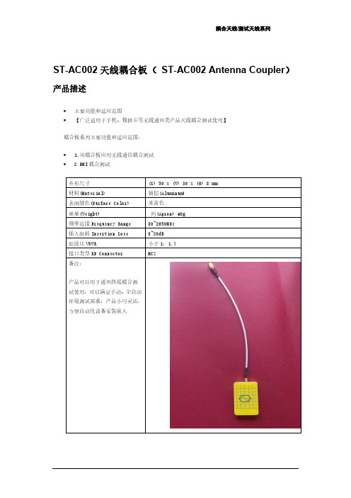
天线耦合板TC-93061A
原理功能:
天线耦合板的原理是将电路板上电容和电感的电能转换为电磁场,并在固定的方向上传播,相反也可以将外界的电磁场转换为电能,以便最有效的耦合天线上的能量。
作用:1. 实现辐射方式的测量。
2.可再现的一致性测量
适用范围:GSM, PCS, DCS, CDMA, WCDMA, CDMA2000, TD-SCDMA, Wi-Fi, 蓝牙, GPS, DAB/DMB, CMMB, ZigBee, UWB, WiMax, LTE以及各种小型无线通讯设备的研发、生产、质检、实验以及认证部门的测试使用。
部分参数:
频率范围:800 ~ 6000MHz
插入损耗:7 ~ 18dB
驻波比 :优于 1 : 2.2 (Typ1.8)
射频接口 :SMA(f)
重量 :300g
尺寸 :130 x 106 x 15.6 mm
极化方式右旋圆极化(RHCP)
电缆:
4005-0035,SMA(m) R/A to SMA(m) cable, 13cm
4005-0020,N(m) to SMA(m) cable, 1m
4011-0011,SMA(m) R/A to SMA(m) cable, 60cm(5.8GHz)
4011-0004, SS-402, N(m) to SMA(m) cable, 1m(5.8GHz)
北京联华行代理。
Tekelec EAGLE® 5 Integrated Signaling SystemMaintenance Manual910-5272-001 Revision BMay 2008Copyright 2008 TekelecAll Rights Reserved.Printed in U.S.A.NoticeInformation in this documentation is subject to change without notice. Unauthorized use, copying, or translation of this documentation can result in civil or criminal penalties.Any export of Tekelec products is subject to the export controls of the United States and the other countries where Tekelec has operations.No part of this documentation may be reproduced, translated, or transmitted in any form or by any means, electronic or mechanical, including photocopying or recording, for any purpose without the express written permission of an authorized representative of Tekelec.Other product names used herein are for identification purposes only, and may be trademarks of their respective companies.RoHS 5/6 - As of July 1, 2006, all products that comprise new installations shipped to European Union member countries will comply with the EU Directive 2002/95/EC "RoHS" (Restriction of Hazardous Substances). The exemption for lead-based solder described in the Annex will be exercised. RoHS 5/6 compliant components will have unique part numbers as reflected in the associated hardware and installation manuals.WEEE - All products shipped to European Union member countries comply with the EU Directive 2002/96/EC, Waste Electronic and Electrical Equipment. All components that are WEEE compliant will be appropriately marked. For more information regarding Tekelec's WEEE program, contact your sales representative.TrademarksThe Tekelec logo, EAGLE, G-Flex, G-Port, IP7, IP7 Edge, and IP7 Secure Gateway are registered trademarks of Tekelec. TekServer, A-Port, and V-FLEX are trademarks of Tekelec. All other trademarks are the property of their respective owners. PatentsThis product is covered by one or more of the following U.S. and foreign patents:U.S. Patent Numbers:5,732,213; 5,953,404; 6,115,746; 6,167,129; 6,324,183; 6,327,350; 6,456,845; 6,606,379; 6,639,981; 6,647,113; 6,662,017; 6,735,441; 6,745,041; 6,765,990; 6,795,546; 6,819,932; 6,836,477; 6,839,423; 6,885,872; 6,901,262; 6,914,973; 6,940,866; 6,944,184; 6,954,526;6,954,794; 6,959,076; 6,965,592; 6,967,956; 6,968,048; 6,970,542; 6,987,781; 6,987,849; 6,990,089; 6,990,347; 6,993,038; 7,002,988; 7,020,707; 7,031,340; 7,035,239; 7,035,387; 7,043,000; 7,043,001; 7,043,002; 7,046,667; 7,050,456; 7,050,562; 7,054,422; 7,068,773; 7,072,678; 7,075,331; 7,079,524; 7,088,728; 7,092,505; 7,108,468; 7,110,780; 7,113,581; 7,113,781; 7,117,411; 7,123,710; 7,127,057; 7,133,420; 7,136,477; 7,139,388; 7,145,875; 7,146,181; 7,155,206; 7,155,243; 7,155,505; 7,155,512; 7,181,194; 7,190,702; 7,190,772; 7,190,959; 7,197,036; 7,206,394; 7,215,748; 7,219,264; 7,222,192; 7,227,927; 7,231,024; 7,242,695; 7,254,391; 7,260,086; 7,260,207; 7,283,969; 7,286,516; 7,286,647; 7,286,839; 7,295,579; 7,299,050; 7,301,910; 7,304,957; 7,318,091; 7,319,857; 7,327,670Foreign Patent Numbers:EP1062792; EP1308054; EP1247378; EP1303994; EP1252788; EP1161819; EP1177660; EP1169829; EP1135905;EP1364520; EP1192758; EP1240772; EP1173969; CA2352246Ordering InformationTo order additional copies of this document, contact your Tekelec Sales Representative.Table of Contents Chapter 1. Introduction ..................................................................................................... 1-1Overview .................................................................................................................................... 1-1Scope and Audience ................................................................................................................... 1-2Related Publications ................................................................................................................... 1-2Documentation Availability, Packaging, and Updates ............................................................... 1-2Locate Product Documentation on the Customer Support Site .................................................. 1-3Admonishments and Conventions .............................................................................................. 1-4Customer Care Center ................................................................................................................ 1-4Problem Report (PR) ........................................................................................................... 1-5Emergency Response .......................................................................................................... 1-6Hardware Repair and Return ...................................................................................................... 1-6Maintenance Strategy ................................................................................................................. 1-9Application Self Recovery .................................................................................................. 1-9System Maintenance Software Intervention ........................................................................ 1-9Maintenance Personnel Intervention ................................................................................. 1-10System Maintenance Log ......................................................................................................... 1-10 Chapter 2. Preventive Maintenance ................................................................................. 2-1Introduction ................................................................................................................................ 2-1Maintaining the Fuse and Alarm Panel ...................................................................................... 2-21U FAP P/N 870-2804-01 ................................................................................................... 2-33U FAP ................................................................................................................................ 2-8MO Removable Cartridge Description ..................................................................................... 2-15Removable Cartridge Handling Procedures ............................................................................. 2-17Daily Procedures ....................................................................................................................... 2-18System Reports Analysis ................................................................................................... 2-19Reports Description ........................................................................................................... 2-19File Transfer for LNP and INP Measurements ................................................................. 2-20Weekly Procedures ................................................................................................................... 2-21Printer Inspection .............................................................................................................. 2-22Remote Access Verification .............................................................................................. 2-22Monthly Procedures .................................................................................................................. 2-23FAP Load Balance Verification (PN 870-0243-XX only) ................................................ 2-24Change the Fan Tray Filter ................................................................................................ 2-28Changing the Air Supply Filter ......................................................................................... 2-28Cleaning Printer ................................................................................................................. 2-29Fuse Spares Inventory ....................................................................................................... 2-30Wrist Strap Test ................................................................................................................. 2-30Quarterly Procedures ................................................................................................................ 2-31 910-5272-001 Revision B, May 2008iTable of Contents Maintenance ManualPreventing Dust Buildups .................................................................................................. 2-31Rectifier Voltage Inspection/Recording ............................................................................ 2-32 Semi-Annual Procedures .......................................................................................................... 2-32Chapter 3. Corrective Maintenance ................................................................................. 3-1 Introduction .............................................................................................................................. 3-19System Alarm Levels ................................................................................................................ 3-20 Critical ............................................................................................................................... 3-20Major ................................................................................................................................. 3-20Minor ................................................................................................................................. 3-20 Trouble Detection ..................................................................................................................... 3-20 Audible Alarms ................................................................................................................. 3-20Visual Alarms .................................................................................................................... 3-21MDAL LEDs ..................................................................................................................... 3-21Alarm LEDs on the Fuse and Alarm Panel (FAP) ............................................................ 3-22Alarms appearing on a terminal screen ............................................................................. 3-25Alarms on Application Cards ............................................................................................ 3-26End Cabinet Alarm Indicators ........................................................................................... 3-26Event/Error Messages ........................................................................................................ 3-26IMT Bus States .................................................................................................................. 3-26IMT System Alarm Level Determination ......................................................................... 3-27 Unsolicited Alarm Messages (UAM) ....................................................................................... 3-28Unsolicited Information Messages ........................................................................................... 3-43Output Messages ....................................................................................................................... 3-56UAM/UIM Changes ................................................................................................................. 3-57 EAGLE 5 ISS Release 33.0 UAM/UIM Changes ............................................................. 3-57EAGLE 5 ISS Release 34.0 UAM/UIM Changes ............................................................. 3-63EAGLE 5 ISS Release 34.3 UAM/UIM Changes ............................................................. 3-66EAGLE 5 ISS Release 35.0 UAM/UIM Changes ............................................................. 3-67EAGLE 5 ISS Release 35.1 UAM/UIM Changes ............................................................. 3-71EAGLE 5 ISS Release 36.0 UAM/UIM Changes ............................................................. 3-71EAGLE 5 ISS Release 37.0 UAM/UIM Changes ............................................................. 3-72EAGLE 5 ISS Release 37.5 UAM/UIM Changes ............................................................. 3-73 Alarm Clearing Procedures ...................................................................................................... 3-75Retrieve Trouble Report ........................................................................................................... 3-75Hourly Status Message Reports ................................................................................................ 3-76Maintenance System Event Logs ............................................................................................. 3-80Obituaries .................................................................................................................................. 3-82Terminal Not Responding ........................................................................................................ 3-82Printer Not Working ................................................................................................................. 3-84Modem Not Working ................................................................................................................ 3-85Remove Removable Cartridge Stuck in Drive on MDAL ....................................................... 3-85Link Maintenance ..................................................................................................................... 3-87 Link Fault Sectionalization ............................................................................................... 3-87Hardware Configuration .................................................................................................... 3-88Test Indicators ................................................................................................................... 3-90Test Report ........................................................................................................................ 3-91LFS Test Details ................................................................................................................ 3-91 ii910-5272-001 Revision B, May 2008Maintenance Manual Table of ContentsLink Maintenance Enhancements ..................................................................................... 3-93 Power Down of In-Service System .......................................................................................... 3-99Power Up of the System ......................................................................................................... 3-101UAM and UIM Troubleshooting Procedures ......................................................................... 3-101 0001 - Card has reset ....................................................................................................... 3-1020002 - Card is not running approved GPL ...................................................................... 3-1020003 - Alarm cleared for GPL ......................................................................................... 3-1090004 - Card is running non-activated GPL ..................................................................... 3-1090005 - Alarm cleared running non-activated GPL .......................................................... 3-1100008 - Active MASP has become isolated ...................................................................... 3-1100009 - MASP became active ........................................................................................... 3-1100010 - MASP became standby ........................................................................................ 3-1110011 - Entering forced simplex mode ............................................................................. 3-1110013 - Card is isolated from the system .......................................................................... 3-1120014 - Card is present ...................................................................................................... 3-1130018 - Exiting forced simplex mode ............................................................................... 3-1140021 - Clock A for card failed, B normal ........................................................................ 3-1140022 - Clock B for card failed, A normal ........................................................................ 3-1150023 - Clocks A and B for card failed ............................................................................. 3-1160024 - Clock A for card normal ...................................................................................... 3-1160025 - Clock B for card normal ....................................................................................... 3-1170026 - Clocks A and B for card normal .......................................................................... 3-1170033 - Card database has been corrected ........................................................................ 3-1170034 - Card database is inconsistent ............................................................................... 3-1180035 - Card database is corrupted ................................................................................... 3-1200036 - Card backup database has been corrected ............................................................ 3-1220037 - Card backup database is inconsistent ................................................................... 3-1220038 - Card backup database is corrupted ....................................................................... 3-1230039 - GPL has been corrected ....................................................................................... 3-1230040 - GPL is corrupted .................................................................................................. 3-1240041 -LSMS bulk load required ...................................................................................... 3-1240042 - LSMS bulk load complete .................................................................................... 3-1240043 - Incorrect feature configuration ............................................................................. 3-1250044 - Real time clock battery low ................................................................................. 3-1250045 - Real time clock battery restored ........................................................................... 3-1250046 - Terminal enabled .................................................................................................. 3-1260047 - Card type not valid for application ...................................................................... 3-1260048 - Terminal failed ..................................................................................................... 3-1260051 - TSC sync is in simplex mode ............................................................................... 3-1270052 - TSC sync feature is available ............................................................................... 3-1270053 - Standby TDM failure ........................................................................................... 3-1270054 - Standby TDM failure cleared ............................................................................... 3-1280055 - Persistent device state tbl corrupt ......................................................................... 3-1280056 - Persistent device state tbl diff version .................................................................. 3-1290057 - Persistent device state tbl corrected ..................................................................... 3-1290058 - Critical customer trouble detected ....................................................................... 3-1290059 - Major customer trouble detected .......................................................................... 3-1300060 - Minor customer trouble detected ......................................................................... 3-130 910-5272-001 Revision B, May 2008iiiTable of Contents Maintenance Manual0061 - Customer trouble detected ................................................................................... 3-1300062 - Customer trouble cleared ..................................................................................... 3-1310063 - Critical holdover clock trbl detected .................................................................... 3-1310064 - Major holdover clock trouble detected ................................................................ 3-1310065 - Minor holdover clock trouble detected ................................................................ 3-1310066 - Holdover clock trouble cleared ............................................................................ 3-1320077 - Card temperature is critical lvl:T2 ....................................................................... 3-1320078 - Card temperature exceeds nominal lvl:T1 ........................................................... 3-1340079 - Card temperature again at nominal levels ............................................................ 3-1360082 - Alarm in Fuse panel ............................................................................................. 3-1360083 - Fuse Panel alarm has cleared ............................................................................... 3-1370084 - IP Connection Unavailable .................................................................................. 3-1380085 - IP connection available ........................................................................................ 3-1410086 - IP Connection Congested ..................................................................................... 3-1410087 - IP Connection manually removed ........................................................................ 3-1420088 - Clocks A and B TSCs are out of sync .................................................................. 3-1420089 - Clocks A and B TSCs are resynchronized ........................................................... 3-1430092 - MDAL not responding ......................................................................................... 3-1430093 - MDAL alarm cleared ........................................................................................... 3-1430096 - Card has been reloaded ........................................................................................ 3-1440097 - IMT allowed ......................................................................................................... 3-1440098 - IMT inhibited ....................................................................................................... 3-1440099 - Incompatible HW for provisioned slot ................................................................. 3-1450102 - Motherboard BIP invalid ..................................................................................... 3-1450103 - Motherboard BIP valid ......................................................................................... 3-1460106 - IMT Bus alarm cleared ........................................................................................ 3-1460107 - Minor IMT failure detected .................................................................................. 3-1460108 - Major IMT failure detected .................................................................................. 3-1480109 - All IMT System level alarms cleared .................................................................. 3-1510110 - Failure detected on one IMT bus ......................................................................... 3-1510111 - Failure on both IMT A and IMT B ...................................................................... 3-1530112 - Major failures detected on both IMTs .................................................................. 3-1530113 - Clock alarm(s) cleared ......................................................................................... 3-1540115 - Linkset IP TPS threshold exceeded ..................................................................... 3-1540116 - Link expected IP TPS threshold exceeded ........................................................... 3-1550118 - Linkset IP TPS normal ......................................................................................... 3-1550119 - Link IP TPS normal ............................................................................................. 3-1560128 - All clocks have failed ........................................................................................... 3-1560130 - Card successfully loaded with data ...................................................................... 3-1560132 - Loading failed: table not found ............................................................................ 3-1570133 - Loading failed: data read Error ............................................................................ 3-1570134 - Loading failed: bad checksum returned ............................................................... 3-1580135 - Loading failed: GPL load timeout ....................................................................... 3-1580136 - Loading failed: data load timeout ........................................................................ 3-1580137 - Loading failed: invalid GPL ................................................................................ 3-1590138 - Loading failed: GPL format error ........................................................................ 3-1590139 - Loading failed: disk read prep error ..................................................................... 3-1590140 - Loading failed: disk read response error .............................................................. 3-160 iv910-5272-001 Revision B, May 2008Maintenance Manual Table of Contents0141 - Loading failed: disk read failed ........................................................................... 3-1600142 - System release alarm cleared ............................................................................... 3-1600143 - System release GPL(s) not approved ................................................................... 3-1600144 - System release version unknown ......................................................................... 3-1610145 - HS Clock A for card failed, B normal ................................................................. 3-1610146 - HS Clock B for card failed, A normal ................................................................. 3-1620147 - High Speed Clocks A and B for card failed ......................................................... 3-1630148 - High Speed Clock A for card normal ................................................................... 3-1640149 - High Speed Clock B for card normal ................................................................... 3-1640150 - STPLAN is available ........................................................................................... 3-1650151 - STPLAN capacity normal,card(s) abnormal ........................................................ 3-1650152 - LIM(s) have been denied STPLAN service ......................................................... 3-1660153 - STPLAN not available ......................................................................................... 3-1660154 - STPLAN is removed ............................................................................................ 3-1670155 - STPLAN connection unavailable ......................................................................... 3-1670156 - STPLAN connection available ............................................................................. 3-1680157 - X25 logical channels available ............................................................................ 3-1680158 - X25 no logical channels available ....................................................................... 3-1680159 - High Speed Clocks A and B for card normal ....................................................... 3-1690160 - 1116-S clock failed .............................................................................................. 3-1690161 - 1116-P clock failed .............................................................................................. 3-1690162 - 1116-P, 1116-S clocks failed ............................................................................... 3-1700163 - 1114-S clock failed .............................................................................................. 3-1700164 - 1114-S, 1116-S clocks failed ............................................................................... 3-1710165 - 1114-S, 1116-P clocks failed ............................................................................... 3-1710166 - 1114-S, 1116-P, 1116-S clocks failed .................................................................. 3-1720167 - 1114-P clock failed .............................................................................................. 3-1730168 - 1114-P, 1116-S clocks failed ............................................................................... 3-1730169 - 1114-P, 1116-P clocks failed ............................................................................... 3-1740170 - 1114-P, 1116-P, 1116-S clocks failed .................................................................. 3-1740171 - 1114-P, 1114-S clocks failed ............................................................................... 3-1750172 - 1114-P, 1114-S, 1116-S clocks failed .................................................................. 3-1750173 - 1114-P, 1114-S, 1116-P clocks failed .................................................................. 3-1760174 - %full threshold reached -upload required ............................................................ 3-1770175 - LOGBUFROVFL-SECULOG - upload required ................................................ 3-1770176 - Stdby security log - upload required .................................................................... 3-1780177 - Security log exception cleared ............................................................................. 3-1780178 - Security log failed ................................................................................................ 3-1780179 - NDC Q.3 association is unavailable .................................................................... 3-1790180 - NDC Q.3 association is available ........................................................................ 3-1790181 - NDC Subsystem is not available .......................................................................... 3-1790182 - NDC Subsystem is available ................................................................................ 3-1810183 - 1116-SHS clock failed ......................................................................................... 3-1810184 - 1116-PHS clock failed ......................................................................................... 3-1820185 - 1116-PHS, 1116-SHS clocks failed ..................................................................... 3-1820186 - 1114-SHS clock failed ......................................................................................... 3-1830187 - 1114-SHS, 1116-SHS clocks failed ..................................................................... 3-1840188 - 1114-SHS, 1116-PHS clocks failed ..................................................................... 3-184 910-5272-001 Revision B, May 2008v。
6-port sector antenna, 2x 698–960 and 4x 1710–2690 MHz, 65°HPBW, 3x RET with manual override.Integrated Internal Remote Electrical Tilt (RET), with independent control of electrical tilt withmanual override on all arraysOBSOLETEThis product was discontinued on: March 27, 2020General SpecificationsAntenna Type SectorBand MultibandGrounding Type RF connector inner conductor and body grounded to reflector andmounting bracketPerformance Note Outdoor usageRadome Material ASA, UV stabilizedRadiator Material Brass | Low loss circuit boardReflector Material AluminumRF Connector Interface7-16 DIN FemaleRF Connector Location BottomRF Connector Quantity, high band4RF Connector Quantity, low band2RF Connector Quantity, total6Remote Electrical Tilt (RET) InformationRET Interface8-pin DIN Female | 8-pin DIN MaleRET Interface, quantity 3 female | 3 maleInput Voltage10–30 VdcInternal RET High band (2) | Low band (1)Power Consumption, idle state, maximum 2 WPower Consumption, normal conditions, maximum13 WProtocol3GPP/AISG 2.0 (Single RET)16Page ofPage of 26DimensionsWidth 353 mm | 13.898 in Depth 209 mm | 8.228 in Length2065 mm | 81.299 in Net Weight, without mounting kit28 kg | 61.729 lbArray LayoutElectrical SpecificationsImpedance50 ohmOperating Frequency Band 1710 – 2690 MHz | 698 – 960 MHz Polarization±45°Electrical SpecificationsFrequency Band, MHz698–790790–890890–9601710–19201920–21702300–2690 Gain, dBi15.315.516.11818.419.2 Beamwidth, Horizontal,degrees68.268.8636263.362 Beamwidth, Vertical, degrees12.41110.1 5.8 5.1 4.2Beam Tilt, degrees0–100–100–100–100–100–10 USLS (First Lobe), dB181818181814Null Fill, dB-22-22-22-22-22-22Front-to-Back Ratio at 180°,dB252425293331CPR at Boresight, dB171212191615CPR at Sector, dB109.697.1 5.34 Isolation, Cross Polarization,dB252525252525 Isolation, Inter-band, dB303030303030VSWR | Return loss, dB 1.43 | 15.0 1.43 | 15.0 1.43 | 15.0 1.5 | 14.0 1.5 | 14.0 1.5 | 14.0 PIM, 3rd Order, 2 x 20 W, dBc-150-150-150-150-150-150Input Power per Port,maximum, watts300300300250250250 Electrical Specifications, BASTAFrequency Band, MHz698–790790–890890–9601710–19201920–21702300–2690 Gain by all Beam Tilts,average, dBi14.815.115.717.618.118.6Gain by all Beam TiltsTolerance, dB±0.2±0.2±0.2±0.6±0.3±0.6Gain by Beam Tilt, average, dBi 0 ° | 14.95 ° | 14.810 ° | 14.70 ° | 15.15 ° | 15.110 ° | 15.00 ° | 15.75 ° | 15.710 ° | 15.60 ° | 17.65 ° | 17.610 ° | 17.60 ° | 18.05 ° | 18.010 ° | 18.10 ° | 18.65 ° | 18.710 ° | 18.3Beamwidth, HorizontalTolerance, degrees±1.2±2±1.7±2.8±5.4±6.6Beamwidth, VerticalTolerance, degrees±0.8±0.6±0.4±0.3±0.4±0.3USLS, beampeak to 20° abovebeampeak, dB181818181818Front-to-Back Total Power at180° ± 30°, dB25.323.123.623.424.925.4CPR at Boresight, dB16131319181811108755Page of36CPR at Sector, dB11108755 Mechanical SpecificationsWind Loading @ Velocity, frontal926.0 N @ 150 km/h (208.2 lbf @ 150 km/h)Wind Loading @ Velocity, lateral355.0 N @ 150 km/h (79.8 lbf @ 150 km/h)Wind Loading @ Velocity, rear951.0 N @ 150 km/h (213.8 lbf @ 150 km/h)Wind Speed, maximum250 km/h (155 mph)Packaging and WeightsWidth, packed430 mm | 16.929 inDepth, packed325 mm | 12.795 inLength, packed2260 mm | 88.976 inWeight, gross45 kg | 99.208 lbRegulatory Compliance/CertificationsAgency ClassificationCE Compliant with the relevant CE product directivesCHINA-ROHS Above maximum concentration valueISO 9001:2015Designed, manufactured and/or distributed under this quality management system REACH-SVHC Compliant as per SVHC revision on /ProductComplianceROHS Compliant/ExemptedUK-ROHSCompliant/ExemptedIncluded ProductsT-029-GL-E–Adjustable Tilt Pipe Mounting Kit for 2.362"-4.5" (60-115mm) OD round members for panelantennas. Includes 2 clamp sets.* FootnotesPerformance Note Severe environmental conditions may degrade optimum performancePage of46Adjustable Tilt Pipe Mounting Kit for 2.362"-4.5" (60-115mm) OD roundmembers for panel antennas. Includes 2 clamp sets.Product ClassificationProduct Type Adjustable tilt mounting kitGeneral SpecificationsApplication OutdoorColor SilverDimensionsCompatible Length, maximum2850 mm | 112.205 inCompatible Length, minimum1500 mm | 59.055 inCompatible Diameter, maximum115 mm | 4.528 inCompatible Diameter, minimum60 mm | 2.362 inAntenna-to-Pipe Distance85 mm | 3.346 inBracket-to-Bracket Distance1400 mm | 55.118 inWeight, net 6 kg | 13.228 lbMaterial SpecificationsMaterial Type Galvanized steelMechanical SpecificationsMechanical Tilt0°–8°Packaging and WeightsIncluded Brackets | HardwarePackaging quantity1Regulatory Compliance/CertificationsAgency ClassificationCE Compliant with the relevant CE product directives56Page ofCHINA-ROHS Below maximum concentration valueISO 9001:2015Designed, manufactured and/or distributed under this quality management system REACH-SVHC Compliant as per SVHC revision on /ProductCompliance ROHS CompliantUK-ROHSCompliantPage of66。
迪泰科技风语系列HTS-6063cm KU波段VSAT通讯天线安装及操作手册宁波迪泰电子科技有公司迪泰科技公司简介宁波迪泰电子科技有限公司是一家从事船载卫星通信设备研发、生产、销售、运营于一体的高科技公司,公司于2010年5月注册成立,座落于宁波高新区聚贤路1299号博邦工业园区。
旗下成立三家全资控股公司:迪泰(浙江)通信技术有限公司主要从事船用卫星通信设备的研发、生产、销售一体的公司;捷信(浙江)通信技术有限公司是一家从事卫星通信带宽运营的公司,为海上船只提供基于卫星通信的互联网宽带,语音,视频等接入服务;浙江泽洋网云科技有限公司是一家互联网公司,主要从事软件开发、海上互联网应用,海上物联网及大数据等应用服务。
公司总人数200人,大专以上学历122人,已申请专利证书67项,其中发明专利13项、实用新型32项、软著22项,公司及旗下子公司均已通过中国船级社(CCS)的质量管理体系认证及产品型式认可资质、获得国家工信部颁发的增值电信业务许可证:ICP、VSAT、ISP、SP等证书。
公司将继续秉承“科技创新,永不止步”的企业精神,践行“一带一路”战略构想,力求让客户“随时随地,享受海上品质生活”,打造智慧海洋生态圈。
1. 产品介绍1.1 天线介绍1.2 产品特征1.3 天线系统配置说明2.天线安装说明2.1 系统所有物2.2 天线选址注意事项2.3 天线安装要点3.通用控制器安装操作说明3.1 通用控制器简介3.2 通用控制器安装说明3.3 通用控制器键位及接口说明3.4 通用控制器相关操作说明3.5 通用控制器规格参数4.AP安装连接说明4.1 AP简介4.2 AP安装说明5.SIP电话安装操作说明5.1 SIP电话简介5.2 SIP电话安装说明5.3 SIP电话连接说明5.4 SIP电话键位及功能说明6.船用天线手机APP安装操作说明6.1 APP简介6.2 用户自主注册及开户操作说明6.3 APP功能介绍7.设备异常处理方法目 录迪泰科技1126779101313141518202121212222222425262626273233 8.HTS-60天线内部结构概览1.1天线介绍波段卫星通讯功能,使船舶在动态状况下实现船舶实时视频监控、船舶宽带上网、船舶网络电视、船舶远程视频会议、VOIP语音电话等功能需求。