BGK-FBG-8210便携式解调仪使用手册中文
- 格式:pdf
- 大小:1.61 MB
- 文档页数:73
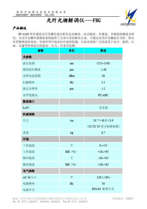

B LUETOOTH E ASY R EADERB OXC ONTENTS1 InfoChip Bluetooth Easy Reader HF 13.56 RFID Reader, 1 Wrist Lanyard (installed), 1 Spare USB Dust Cover 1 Silicone Protective Sleeve (installed), 1 USB Cable (for charging only)C HARGING1. Gently open the USB Dust Cover and insert the supplied USB cable into the mini USB port on the Reader.2. Ensure the dust cover is completely out of the way of the USB cable as you insert it.3. Plug the other end of the USB cable into a USB 2.0 port on a computer, or into a UL-Approved standard USB wall charger.4.The LED light on the Reader should flash green while charging, and turn to solid green when fully charged.R EADING AN RFID CHIP IN S TANDALONE M ODE1. Ensure Bluetooth is OFF. See “Changing Bluetooth Mode” below if Bluetooth is not OFF.2. Press the button once and release it immediately. You will now have approximately 7 seconds to scan a chip. Guide the tip of the readerdirectly above the face of the chip to be scanned. Some chips may need to be scanned with the flat surface of the scanning tip brought very close to the flat chip surface. As needed, gentle contact to the chip is okay. See Figure 1.3. Once the tip is within range of the RFID chip, the Reader will beep, the display will turn green, and the scanned ChipID will be displayedon the top line of the display. The previous ChipID is displayed on the bottom line of the display. See Figure 2.Figure 1 (Scanning)Figure 2 (Successful scan)ButtonBattery/Charge Indicator LED Display ScreenScanning TipWrist LanyardUSB Charging PortQ UICK S TART G UIDENewly Scanned ChipID Previously Scanned ChipIDFor more information, visit: RDR-HF-BTDISP1-QS REVISION 1.1T URNING B LUETOOTH O N AND O FF1. Press and Hold the button until the menu appears, then release the button. See Figure 3.2. Click and Release the button repeatedly until the Bluetooth ON/OFF page is displayed. See Figure 4.3. Now Press and Hold the button to toggle the Bluetooth setting ON or OFF. When Bluetooth is ON, more Bluetooth menu options will beavailable. See Figure 5.Figure 3 (Menu)Figure 4 (Bluetooth OFF) Figure 5 (Bluetooth ON)P RACTICE E NTERING P AIRING C ODES (PIN S )When pairing to a host device, the host device may ask you to enter a pairing code or PIN from 4 to 8 digits in length. Generally you have about 30 seconds to enter this PIN on the Reader. This can be difficult initially, but becomes easy with some practice. We have provided a Practice PIN menu option that will allow you to enter random pairing codes so you can familiarize yourself with the metho d. Let’s practice entering “7654”.1. To get into Practice PIN mode, Press and Hold the button until the menu appears. Then Click and Release the button repeatedly until thePractice PIN menu option is displayed. See Figure 10.2. Press and Hold to enter the Practice Pin mode. (The first digit 0 appears). To change the first digit, click and release the button quicklyand repeatedly (this is called a Short Press) until the desired digit “7” is displayed. See Figure 11.3. To move to the next digit, press and hold the button for more than 0.5 seconds but less than 1 second. This is called a Medium Press.The 2nddigit will show “0”. Short Press until the desired digit “6” is displayed. See Figure 12.4. Medium Press to move to the 3rd digit, then Short Press to until “5” is displayed. Medium Press to move to the 4thdigit, then Short Pressrepeatedly until the desired digit “4” is displayed. See Figure 13.5. Now that your desired “7654” PIN is shown, use a Long Press (press and hold) until the code is accepted. Keep experimenting until youare familiar with the method of entering PINs.Figure 10 (Practice PIN) Figure 11 Figure 12 Figure 13P AIRING TO AH OST D EVICE(P HONE /HANDHELD /L APTOP )The InfoChip Bluetooth Easy RFID Reader appears and acts as a Bluetooth keyboard. It can pair to most devices that accept the Bluetooth keyboard profile without driver software. If you are not in the menu system already, Press and hold the button until the menu appears, then release it.1. Click and Release the button repeatedly to scroll through the menu options. Stop when you arrive at the screen labeled Pair as Keyboard .See Figure 6.2. Press and Hold the button to set the Reader into pairing mode, which should cause the display to flash, indicating the Reader is ready topair. See Figure 7. Now turn on Bluetooth on your host device and begin searching for a device to pair with. Please refer to your device’s manual for instructions on how to turn its B luetooth on and how to place it into pairing mode.3. Once your host device finds the InfoChip keyboard, select it for pairing. Your host device should ask you to enter a pairing code on theReader, which you will have approximately 25 seconds to accomplish. See Figure 8. Please see the section “Practice Entering Pairing Codes ” to successfully accomplish this step. Once you have entered that pairing code successfully on the Reader in the allotted time, the pairing process is complete. See Figure 9. Exit the menu and now your host device should be ready to accept scanned ChipIDs from the Reader. If you did not complete the pairing successfully your device will tell you, and you must repeat steps 1 to 3 above until successful.Figure 6 (Pair as Keyboard) Figure 7 (Pairing) Figure 8 (Pairing PIN) Figure 9 (Pairing Complete)R EADING A C HIP W HILE C ONNECTED TO A H OST D EVICE1. Ensure Bluetooth is turned ON.2. Ensure the Reader has been paired successfully to your host device using the instructions above.3. On your host device, start any application that accepts text input (such as Notes, Email, etc).4.Short Press the button on the Reader. The Reader’s display should read “Bluetooth Trying To Connect” and it should quickly find your host device, at which time the Reader will begin flashing and beeping and trying to scan a chip. You now have approximately 7 seconds to place the tip of the Reader up to the face of the chip to be read. In doing so, the unique ChipID of the scanned chip (which should be similar to E004010014F25431) will be entered at the active cursor location of the host device.For more information, visit: RDR-HF-BTDISP1-QS REVISION 1.1。
《光纤Bragg光栅温度-应变解调仪设计》篇一光纤Bragg光栅温度-应变解调仪设计一、引言随着光纤传感技术的不断发展,光纤Bragg光栅(FBG)作为一种重要的光纤传感器件,在许多领域中得到了广泛的应用。
其能够通过检测反射回来的特定波长光来获取外部环境的温度、应变等信息。
因此,设计一个高性能的光纤Bragg光栅温度/应变解调仪显得尤为重要。
本文旨在探讨光纤Bragg光栅温度/应变解调仪的设计原理、关键技术及实现方法。
二、系统设计原理光纤Bragg光栅温度/应变解调仪的核心原理是利用宽带光源发出的光经过光纤Bragg光栅后,反射回特定波长的光信号,通过解调仪对反射光的波长进行检测,从而推算出外部环境的温度或应变信息。
三、硬件设计(一)光源模块光源模块采用宽带光源,具有较高的稳定性和可靠性。
同时,为提高解调仪的灵敏度,需确保光源的波长范围能够覆盖光纤Bragg光栅的反射波长。
(二)光纤Bragg光栅模块光纤Bragg光栅模块是整个系统的核心部件,其性能直接影响到解调仪的精度和稳定性。
该模块需具备高灵敏度、高分辨率和良好的稳定性。
(三)解调模块解调模块负责检测反射光的波长,并将其转换为温度或应变信息。
该模块需采用高精度的光谱检测技术,如光谱分析仪或高速光谱仪等。
(四)数据处理与输出模块数据处理与输出模块负责将解调模块输出的数据进行处理和转换,以便于用户使用。
该模块需具备高速数据处理能力和友好的人机交互界面。
四、软件设计软件设计是光纤Bragg光栅温度/应变解调仪的重要组成部分,主要包括数据采集、数据处理、数据存储与传输等部分。
软件需具备实时性、稳定性和可扩展性等特点,以适应不同应用场景的需求。
(一)数据采集软件通过与硬件模块的通信接口,实时采集反射光的波长信息。
同时,软件需对采集到的数据进行预处理,如去除噪声、平滑处理等。
(二)数据处理数据处理是软件的核心部分,包括波长到温度/应变的转换、数据校正、数据存储等。

武汉中地恒达科技有限公司企业标准ZDHD-QS-JS039-1.0-2020光纤光栅静态解调仪使用说明书2020-6-1实施本说明书由武汉中地恒达科技有限公司编制1.硬件设备说明1.1产品简介FBG-2000是武汉中地恒达科技有限公司研发设计的一款专用监测仪器,配套光纤光栅传感器使用。
专用于桥梁、隧道、大坝、边坡等的工程结构在线监测。
具有多种多功能、操作简单、接口方便,同时适合于用户进行二次开发。
产品采用了先进的技术路线,采集出带宽范围内的海量光谱点,并根据运算规则计算出光谱中峰值的中心位置。
同时结合了工程应用的需要。
系统既提供高精度的波长分辨率,又满足工程环境长期稳定运行的要求。
FBG-2000主机采用优化的数字逻辑进行电路运算处理,可以快速找到中心波长的位置。
同时采用光学标准具进行校准,保证系统温度测量的准确性和稳定性。
其主机设计包括的基本配置:扫描光源,光探测器,电路、软件处理、光路、电源等部分组成,系统最大化地集成了各个模块,使得各模块独立工作,又互相联系,保证了系统的良好的一致性,也方便了用户的使用维修。
钢筋计适用于长期埋设在混凝土结构物内部,测量结构物内部的钢筋应力。
1.2装箱清单光纤光栅解调仪主机x1铝合金包装箱x1电源线x1检测报告x1合格证x1使用说明书x1 1.3产品规格指标1.4产品内部结构示意图外接传感器光学系统电路系统工控机(windows)外接键、鼠、显示器与通讯网络1.5对外接口光纤FC 接口用于连接传感器网口对外通讯AC220V 电源口USB主要用于接鼠标键盘、U 盘VGA 或HDMI 主要用于内置工控机时接显示器1.6相比于同类产品的优势【设备信噪比高】下图为本产品与同行产品的对比,在外接相同传感器、相同条件下运行,本产品的波长白噪声约为±1pm,同行的产品白噪声达到±15pm(对外宣称指标为1pm精度)。
本产品的信噪比符合宣称指标并明显优于市场同类产品。
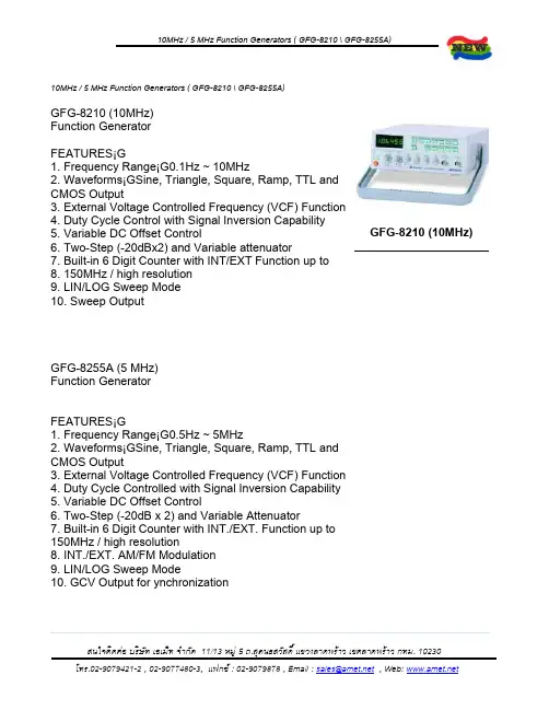
10MHz / 5 MHz Function Generators ( GFG-8210 \ GFG-8255A)Specifications:•10MHz GFG-8210 Specifications:o Maino Frequency Range 0.1Hz ~ 10MHz (8 ranges)o Amplitude >10Vp-p (into 50£[ load)o Impedance 50£[+10%o Attenuator -20dB+1dB x 2o DC Offset <-5V ~ >5V( into 50£[ load)o Duty Control 15% : 85% : 15% to 1MHz Continue variable (square wave only)o Display 6 digits LED displayo---------------------------------------------------------------------------o Sine Waveo Distortion 1% typicalo Flatness + 0.45dB (+5%)o---------------------------------------------------------------------------o Triangle Waveo Linear >98% to 100kHzo----------------------------------------------------------------------------o Square Waveo Symmetry +2%, 1Hz ~ 100kHzo Rise or Fall Time < 35nSo---------------------------------------------------------------------------o CMOS Outputo Max. Frequency 2MHzo Level <4Vpp ~ 14.5Vpp+0.5Vpp adjustableo Rise or Fall Time <120nSo---------------------------------------------------------------------------o TTL Outputo Level >3Vppo Rise or Fall Time <20nSo---------------------------------------------------------------------------o VCFo Input Voltage 0V~10V ¡1V(100 : 1)o Input Impedance 10k£[ ¡0%o---------------------------------------------------------------------------o Sweep Operationo Sweep/Manual Switch selectoro Sweep/Rate >100 : 1 ratio max. and adjustableo Sweep/Time 0.5sec. ~ 30sec. adjustableo Sweep/Mode Lin./Log. switch selectoro Sweep/Out 0V ~ 10+1Vo----------------------------------------------------------------------------o Frequency Countero INT./EXT. Switch selectoro Range 0.1Hz ~ 10MHz (5Hz ~ 150MHz EXT.)o Accuracy Timebase accuracy ¡ counto Timebase ¡Ӳ0ppm (23¢XC¡¢XC) after 30 minutes warm upo Resolution The maximum resolution is 100nHz for 1Hz and 1Hz for 100MHzo Input Impedance 1M£[//150pFo----------------------------------------------------------------------------o Power Source AC 115V/230V¡5%, 50/60Hzo----------------------------------------------------------------------------o Accessories Power cord ¡1,o Instruction manual ¡1,o GTL-101 ¡ 2o----------------------------------------------------------------------------o Dimensions & Weight 251(W) ¡91(H) ¡291(D) mm, Approx. 2.2 kg• 5 MHz GFG-8255A Specifications:o Maino Frequency Range 0.5Hz to 5 MHz (7 ranges)o Amplitude >10Vp-p (into 50£[ load)o Impedance 50£[ +10%o Attenuator -20dB+1dB x 2o DC Offset <-5V ~ >5V (into 50£[ load)o Duty Control 80% : 20% : 80% to 1MHz Continue variable o Display 6 digit LED displayo---------------------------------------------------------------------------o Sine Waveo Distortion <1%, 0.5Hz ~ 100kHzo Flatness <0.3dB, below 500kHz¡F <1dB, below 5MHzo----------------------------------------------------------------------------o Triangle Waveo Linear >98%, 0.5Hz ~ 100kHz¡F >95%, 100kHz ~ 5MHzo---------------------------------------------------------------------------o Square Waveo Symmetry +2%, 1Hz ~ 100kHzo Rise or Fall Time < 50nS at maximum output (into 50£[ load) o----------------------------------------------------------------------------o CMOS Outputo Level 4Vpp+1Vpp ~ 14.5Vpp+0.5Vpp adjustableo Rise or Fall Time <120nSo----------------------------------------------------------------------------o TTL Outputo Level >3Vppo Fan Out 20 TTL loado Rise/Fall Time <25nSo----------------------------------------------------------------------------o VCFo Input Voltage 0V~10V ¡V(100 : 1)o Input Impedance 10k£[ ¡0%o--------------------------------------------------------------------------o GCVo Output Voltage To set the voltage between 0V ~ 2V as per different frequency o----------------------------------------------------------------------------o Sweep Operationo Sweep/Manual Switch selectoro Sweep/Rate 100 : 1 ratio max. and adjustableo Sweep/Time 0.5sec. ~ 30sec. adjustableo Sweep/Mode Lin./Log. switch selectoro----------------------------------------------------------------------------o Amplitude Modulationo Depth 0 ~ 100%o MOD. Frequency 400Hz (INT), DC ~ 1MHz(EXT)o Carrier BW 100Hz ~ 5MHz (-3dB)o EXT Sensitivity <10Vpp for 100% modulationo----------------------------------------------------------------------------o Frequency Modulationo Deviation 0 ~ + 5%o MOD. Frequency 400Hz(INT), DC ~ 20kHz(EXT.)o EXT. Sensitivity <10Vpp for 10% modulationo----------------------------------------------------------------------------o Frequency Countero INT./EXT. Switch selectoro Range 0.5Hz ~ 5MHz (5Hz ~ 150MHz EXT.)o Accuracy Timebase accuracy ¡ Counto Timebase ¡Ӳ0ppm (23¢XC¡¢XC) after 30 minutes warm upo Resolution The maximum resolution is 100nHz for 1Hz and 1Hz for 100MHz o Input Impedance 1M£[//150pFo Sensitivity <35mVrms (5Hz ~ 100MHz)¡F< 45mVrms (100MHz ~ 150MHz)o----------------------------------------------------------------------------o Power Source AC 115V/230V¡5%, 50/60Hzo----------------------------------------------------------------------------o Accessories: Power cord ¡1, Instruction manual ¡1, GTL-101 ¡ 2o----------------------------------------------------------------------------o Dimensions & Weight 251(W) ¡91(H) ¡291(D) mm, Approx. 2.4kg。
宿州市金鼎安全技术研究所文件编号:CZ002 第 1 页共 1 页
仪器使用注意事项
一、主机
1.由于使用激光器件,请勿频繁开关机。
2.可以使用触摸屏或USB鼠标进行操作。
请勿使用尖锐物体刮擦触摸屏表面。
USB口可以连接鼠标或U盘。
请注意:某些USB设备因耗电量大,在本机上可能导致识别不出,属于正常情况,请更换其他设备。
3.锂电池:使用过后,即可充电。
在“欠电”灯亮起后,请及时为锂电池充电。
长期不用每隔15-30天进行一次充电,以保持电池的良好性能。
二、电学接口
1.接口,类型为FC/APC。
接口不用时,请及时旋盖避灰。
2.并口,该接口因为粉尘污染可能导致影响测量,可使用无尘擦拭纸或者棉签蘸取酒精后进行清理。
光学接口有不可见激光发出,请注意防护。
3.使用直流稳压电源可进行充电。
充电状态下仍可正常使用。
BGK-FBG8600L 光纤光栅解调仪产品使用手册版本号:Rev.B发行时间:20212021目录1简介 (1)2安全使用说明 (2)3工作原理 (4)4BGK-FBG8600L型光纤光栅解调仪系统特点 (5)5接口面板说明 (5)5.1主面板接口 (5)5.2后面板接口 (6)5.3接口说明 (6)6主要技术指标 (7)7光栅解调仪配置 (9)7.1通用配置 (10)7.2传感器配置 (12)7.3配置数据采集方式及周期 (12)8BGK-Logger使用说明 (13)8.1软件安装 (13)8.2系统整体结构 (14)8.3系统配置 (15)8.4设备配置 (17)8.5设备控制 (19)8.6数据管理 (20)1简介BGK-FBG8600L型光纤光栅解调仪(以下简称光栅解调仪或解调仪)是基康仪器股份有限公司研制的一款用于自动化测量光纤光栅传感器的采集仪,并有8路、16路两种配置可选。
根据现场使用环境及需求的不同,可配置连续采集、等间隔采集、定点采集等多样化的工作模式。
采集的同时,可通过有线以太网、4G或Wi-Fi方式将数据上传至BGK-Logger软件平台或“G云”云平台。
解调仪内部集成电池,可实现外部掉电不间断测量,使用高精度的可调光纤光源和采集测量系统,具有测量范围大、长期稳定性好、精度高等特点。
适用于桥梁、桩基、水电站、大坝、电厂等各种复杂环境下的光纤光栅传感器数据采集。
图1-1光栅解调仪2安全使用说明下面的符号和信息可能会出现在光栅解调仪上,标识安全符号的目的是使用户避免受到可能的伤害,请注意安全标志以及它们的意义,正确使用仪器以防止可能遇到的危险。
激光安全标志,提醒用户注意激光辐射并安全操作提醒用户根据使用手册正确操作警告,可能有电击危险警告用户如果不严格按照操作手册上步骤操作,可能会导致仪器损坏提示用户如果不严格遵守使用手册上的操作规则,可能会给自己的身体甚至生命带来潜在的危害WARNING:光栅解调仪使用的外部电源为交流220V,使用前清注意选择正确的电压,将随机附送的电源线与机箱后面板的电源接头稳固连接,防止电源不稳定对测量造成影响。

《便携式光纤光栅解调仪研究与设计》篇一一、引言随着光纤传感技术的不断发展,光纤光栅(FBG)作为一种重要的光纤传感器件,在通信、航空航天、生物医疗、环境监测等领域得到了广泛应用。
便携式光纤光栅解调仪作为光纤光栅传感系统中的关键设备,其性能的优劣直接影响到光纤光栅传感系统的应用效果。
因此,研究并设计一款高性能的便携式光纤光栅解调仪具有重要意义。
二、研究背景及意义光纤光栅解调仪是用于检测光纤光栅反射或透射光谱中特定波长变化的关键设备,其性能直接决定了光纤光栅传感系统的测量精度和响应速度。
传统的解调仪通常体积较大、操作复杂,难以满足现场快速检测的需求。
因此,研究并设计一款便携式、高精度、快速响应的光纤光栅解调仪,对于推动光纤光栅传感技术的实际应用具有重要意义。
三、系统设计(一)硬件设计1. 核心处理器:选择高性能的微处理器,负责整个系统的控制与数据处理。
2. 光路设计:包括光源、光纤光栅、探测器等部分,实现光谱的传输与检测。
3. 便携式外壳:采用轻质材料制作外壳,确保设备轻便、耐用。
4. 电源模块:设计高效能电池及充电管理系统,保证设备长时间工作。
(二)软件设计1. 控制算法:编写控制软件,实现对硬件设备的精确控制。
2. 解调算法:采用高精度的解调算法,提高测量精度和响应速度。
3. 用户界面:设计友好的用户界面,方便用户操作。
四、关键技术及创新点(一)关键技术1. 高精度光谱检测技术:采用高精度光谱检测技术,提高测量精度。
2. 快速响应技术:通过优化算法和硬件设计,提高解调速度。
3. 便携式设计技术:采用轻质材料和紧凑设计,实现设备的便携性。
(二)创新点1. 集成化设计:将解调仪的硬件和软件进行高度集成,减小体积,方便携带。
2. 智能化的用户界面:设计智能化的用户界面,实现设备的自动校准和故障诊断。
3. 高性能的解调算法:采用先进的解调算法,提高测量精度和响应速度。
五、实验与测试(一)实验方法1. 制作样机,对硬件和软件进行集成测试。
Rosenberger便携式无源互调分析仪技术文档便携式无源互调分析仪快速操作手册V2.0根据多年无线通信系统运营和网络优化经验, 无源互调干扰往往是造成蜂 窝无线通信基站容量降低和通信质量恶化的最大因素。
作为全世界射频无源连接器第一大生产厂商,罗森伯格在无源互调方面积累了丰富的实际经验, 研发 出了业界领先的无源互调分析仪;同时,罗森伯格通过参与无源互调干扰测试 标准的制定,建立了其在无源互调领域的权威地位。
本文档快速介绍便携式无源互调分析仪操作指导, 便于客户进行操作。
详 细操作指导及其他注意事项,请见《便携式无源互调分析仪操作手册》。
便携式无源互调分析仪前面板示意图如下:点频测试F-vTir ■* 频谱测试扫频范围:•■扫频范围无源互调分析仪快速操作指南1. 连接接地线2. 开机3. 测量阶数设置;若采用默认设置则无需进行此操作4. 点频测试频点设置;若仅用扫频测试则无需进行此操作5. 扫频测试频率范围设置;若仅用点频测试则无需进行此操作6. 功率设置;若采用默认设置则无需进行此操作7. 告警设置;若采用默认设置则无需进行此操作8. 连接被测件9. 无源互调测试10. 关机可以参照以下基本操作快速进行无源互调测试:仪器初始为出厂默认设置, 频率范围为该制式下最大扫频范围。
1.连接地线仪器配置了两端为鳄型夹的接地线,便携式互调分析仪后面板 IEE 488/GPIB接口处专门有一个与接地线相连的金属端子。
在开机测试前需将接地线一端 鳄鱼夹夹紧在金属端子上,另一端鳄鱼夹进行接地。
便携式互调分析仪后面 板接地线安装如下图2.开机 [olI I 关机状态下按开关键超过1秒钟,将启动设备。
检查设备主要参数设 置,包括仪器适用频带、无源互调测试阶数等。
3.测量阶数设置 测量阶数选择,出厂默认设置为三阶。
LB卸一龜舅"豊 B田口aQ口口呂■■■00口口口口口ssss^按“Menu”(屏幕右边第三键),这时候左侧会出现“IM3”,“IM5”,“IM7 三个按键选型,如果测量三阶,就选择“IM3 ”,如果测量五阶,就选择“ IM5 ” 这时屏幕右下方会显示IM3或者IM54.点频测试频点设置按键,进行频点测试设置以GSM900测量5阶、3阶为例(1) GSM测量5阶,点频设置方法f1 :按屏幕左侧“ FREQ”,输入“ 930”,按单位键“ MHz/dBm ”确认f2 :按屏幕右侧“ FREQ”,输入“ 954”,按单位键“ MHz/dBm ”确认⑵GSM测量3阶,点频设置方法f1 :按屏幕左侧“ FREQ”,输入“ 925”,按单位键“ MHz/dBm ”确认f2 :按屏幕右侧“ FREQ”,输入“ 960”,按单位键“ MHz/dBm ”确认常见频段3阶,5阶点频参数参考设置(1) GSM测量5阶,扫频设置方法5.扫频测试频率范围设置f1起始:按屏幕左侧“ START” ,输入“ 930” ,按单位键“ MHz/dBm ”确认f1终止:按屏幕左侧“ STOP”,输入“ 939”,按单位键“ MHz/dBm ”确认f2起始:按屏幕右侧“ START”,输入“ 954”,按单位键“ MHz/dBm ”确认f2终止:按屏幕右侧“ STOP”,输入“ 940”,按单位键“ MHz/dBm ”确认⑵GSM测量3阶,扫频设置方法f1起始:按屏幕左侧“ START”,输入“ 925”,按单位键“ MHz/dBm ”确认f1终止:按屏幕左侧“ STOP”,输入“ 937”,按单位键“ MHz/dBm ”确认f2起始:按屏幕右侧“ START”,输入“ 960”,按单位键“ MHz/dBm ”确认f2终止:按屏幕右侧“ STOP”,输入“ 937”,按单位键“ MHz/dBm ”确认常见频段3阶,5阶扫频参数参考设置仪表测3阶仪表测5阶f1起始f1终止f2起始f2终止f1起始f1终止f2起始f2终止AMPS800869871894889870878893881 GSM900925937960937930941954938 DCS180018051832188018321805182918521815 UMTS210021102114217021602110213321702135 LTE2600262026372695266026352646268026636. 功率设置进行测试功率设置;默认+43dBm为最常见测试功率,无特殊要求不需更改便携式互调分析仪功率设置范围+30dBm~+46dBmF面以设置为+40dBm功率为例f1功率设置:按屏幕左侧“ POWER”,输入“ +40”,按单位键“ MHz/dBm ”确认f2功率设置:按屏幕右侧“ POWER”,输入“ +40”,按单位键“ MHz/dBm ”确认7. 告警线设置按“ Menu”(屏幕右边第三键),进入菜单后―》按“ Preset"键―》按“ Set Limit ”键这时屏幕左侧自上往下会显示三个选项键,如下图“Limit ON ”为告警开关键,按“ Limit ON ”可将告警开关打开,按键显示变成“ Limit OFF ”,再按“ Limit OFF ”可关闭告警。
LB-CNP(B)便携式多参数快速测定仪使用说明书安装、使用本产品前,请详细阅读本使用说明书感谢您选用LB-CNP(B)便携式多参数快速测定仪。
在使用仪器前,请您仔细阅读本使用说明书,从中可以获得有关仪器性能、使用方法以及维护等方面的信息,这会有助于您更好的使用仪器。
如果您有好的建议或需要我们提供更进一步的服务,请按以下方式与我们联系:仪表一部400-6086-707仪表二部400-9929-113室内环保400-6316-707网址:厂址:山东青岛市城阳区金陵工业园锦宏西路与路博路交接口路博1号门。
目录目录 (2)安全警示和注意事项 (3)免责 (4)第1节引言 (5)第2节功能特点与技术参数 (6)第3节.试剂的配制 (8)第4节按键说明 (13)第5节仪器的基本操作 (14)5.1COD的测定 (14)5.1.1方法与原理: (14)5.1.2干扰及消除 (14)5.1.3水样氯离子的测定 (14)5.1.4水样的稀释 (14)5.1.5测定过程 (15)5.2总磷的测定 (19)5.2.1方法与原理: (19)5.2.2干扰和消除 (19)5.2.3水样的稀释 (20)5.2.3测定过程 (20)5.3氨氮的测定 (23)5.3.1方法原理 (23)5.3.2干扰及消除 (23)5.3.3水样的稀释 (23)5.3.4测定过程 (24)5.3.5水样的预处理 (26)5.4测量记录的保存与查询 (27)5.5设置系统时间 (28)5.6测量曲线的选择与修改 (29)第六节仪器校准及曲线的标定 (31)6.1标准溶液的配制: (31)6.2曲线值的校准: (31)第7节消解系统的操作 (34)7.1按键功能介绍 (34)7.2主工作界面及说明 (34)7.3消解器操作说明 (34)7.3.1设置温度参数: (34)7.3.2设置定时参数 (35)7.3.3启动/停止消解过程: (35)7.3.4设置PID参数 (35)第8节常见故障及排除方法 (36)安全警示和注意事项在使用仪器之前,请仔细阅读“安全警示和注意事项”,以确保正确和安全的使用该仪器。
2M误码仪实用操作及保养说明一、规格说明1.前面板、状态告警指示灯2.液晶显示器液晶显示器分为三个部分,如上图所示。
3.按键二、常见技术指标比特率:2048Kb/s ± 50ppm接口:标配75ohm, 高阻,选配:120ohm输入灵敏度:0 ~ - 43dB线路编码:HDB3帧型:无帧,P31,P31C,P30,P30C内部测试序列:伪随机序列: 2^11-1(PR11), 2^15-1(PR15)固定码: 0000(SPACE),1111(MARK),1010(ALT)告警检测和插入:LOS, AIS,LOF, RA误码插入:Single, 10E-3, 10E-6测试标准:G.821,G.826,M.2100单时隙监听:除Ts0外任意单个时隙时钟源选择:内部时钟(Internal),接收回复时钟(Receive)存储:99条电源:4节5号电池或外接电源尺寸:200mm(L) * 100mm(W) * 44mm(H)三、操作说明1.初步操作利用快捷键可以从任何界面直接进入到另一个界面;利用快捷键还可以完成屏幕打印、结果打印、键盘锁定等功能。
任何界面中,当功能扩展键显示时,按键,液晶显示器的左下角会弹出快捷菜单,如图3.2所示,再按键快捷菜单自动利用光标移动键把光标移到所需选项,按ENTER键或F1键选择键盘锁定或直接进入测试设置、当前结果、设置存取、结果存取或仪表设置界面。
2.端口设置2.1 Tx/Rx1/DATA端口设置界面说明 工作方式 发送接收 接口方式 接口方式 信号形式 信号形式 数据端口 数据端口 时钟方式 信号端口 测试图案 测试图案 ① ② 信号码型 信号码型 时隙选择时隙选择①图案极性 ②图案极性界面说明 工作方式 接口方式 接口方式 发送接收 模拟方式 速率 速率 时钟方式 时钟方式 测试图案 测试图案 控制信号① ②③ ④①时钟极性 ②图案极性 ③时钟极性 ④图案极性是接口方式为2Mbit/s 和同向64kbit/s (接口方式为同向64kbit/s 时,相应选项自动无效)时的界面,左边表示发送端口的设置,右边表示接收端口的设置,各栏代表的含义如图2.1所示。
第1篇一、设备准备1. 环境要求解码仪的操作应在通风良好、温度适宜、无腐蚀性气体和电磁干扰的环境中进行。
2. 设备检查操作前,应仔细检查解码仪的各个部件是否完好,包括电源线、信号线、连接线等,确保设备处于正常工作状态。
3. 连接设备将解码仪与待解码设备连接,确保连接牢固。
若解码仪需要与其他设备(如计算机、打印机等)连接,请按照说明书进行操作。
4. 开机打开解码仪的电源开关,等待设备启动完成。
二、操作规程1. 设置参数根据待解码信号的类型和特性,设置解码仪的相关参数。
包括采样频率、采样位数、触发方式、解码模式等。
2. 信号输入将待解码信号输入解码仪,确保信号输入正常。
3. 观察波形在解码仪的显示屏上观察波形,确认信号是否正常。
4. 解码根据设置的参数,解码仪将对输入的信号进行解码处理,并将解码结果输出。
5. 数据处理根据需要,对解码结果进行进一步处理,如滤波、放大、积分等。
6. 数据输出将解码结果输出到计算机、打印机或其他设备,以便进行后续分析和应用。
7. 关闭设备操作完成后,关闭解码仪的电源开关,断开与待解码设备的连接。
三、注意事项1. 操作过程中,请勿触摸解码仪的内部电路,以免造成损坏。
2. 在进行信号输入时,请确保信号幅度在解码仪的输入范围之内。
3. 操作过程中,若发现解码仪出现异常,请立即停止操作,并联系专业人员进行维修。
4. 请勿随意调整解码仪的内部参数,以免影响设备性能。
5. 定期对解码仪进行清洁和保养,确保设备处于良好状态。
四、维护保养1. 定期检查解码仪的各个部件,确保其完好无损。
2. 清洁解码仪的显示屏、按键等部位,保持设备整洁。
3. 检查电源线、信号线等连接线是否牢固,如有松动,请重新连接。
4. 定期对解码仪进行消毒,防止细菌滋生。
5. 按照说明书进行设备保养,确保解码仪处于最佳工作状态。
6. 如发现设备故障,请及时联系专业人员进行维修。
通过以上操作规程,可以确保解码仪的正常使用,提高工作效率。