BEPCⅡ直线加速器的双脉冲加速研究
- 格式:pdf
- 大小:344.43 KB
- 文档页数:6

BEPCⅡ直线加速器定时系统
雷革;徐广磊;汪林;李刚;高文春;乐琪
【期刊名称】《核电子学与探测技术》
【年(卷),期】2007(27)6
【摘要】北京正负电子对撞机升级改造工程BEPCⅡ的重要组成部分——直线加
速器于2006年7月通过了所内预验收,其中定时系统是全新建造的基于EVG/EVR 的事件定时系统,于2006年3月起投入运行,为直线加速器的电子枪、微波激励源、能量倍增器、正电子源、调制器、BPM等设备提供精确的时序触发信号。
本文介
绍直线加速器定时系统的研制、安装调试、运行和改进等工作情况。
【总页数】7页(P1014-1019)
【关键词】BEPCII;直线加速器;定时系统;触发;同步;晃动
【作者】雷革;徐广磊;汪林;李刚;高文春;乐琪
【作者单位】中国科学院高能物理研究所
【正文语种】中文
【中图分类】TP273
【相关文献】
1.BEPCⅡ直线定时系统光信号收发器的研制 [J], 李刚;乐琪;雷革;徐广磊;赵籍九
2.BEPCⅡ直线加速器相控系统的建立 [J], 侯汨;耿哲峤
3.BEPC Ⅱ直线加速器微波系统 [J], 赵风利;侯汨;赵延坪;刘晋通;张敬如;周耀祥;韩
大威
4.BEPC Ⅱ直线加速器相控系统PAD的研制 [J], 耿哲峤;侯汨;裴国玺
5.BEPCⅡ直线加速器相控系统设计研究 [J], 顾鹏达;耿哲峤;崔艳艳;裴国玺;王书鸿因版权原因,仅展示原文概要,查看原文内容请购买。


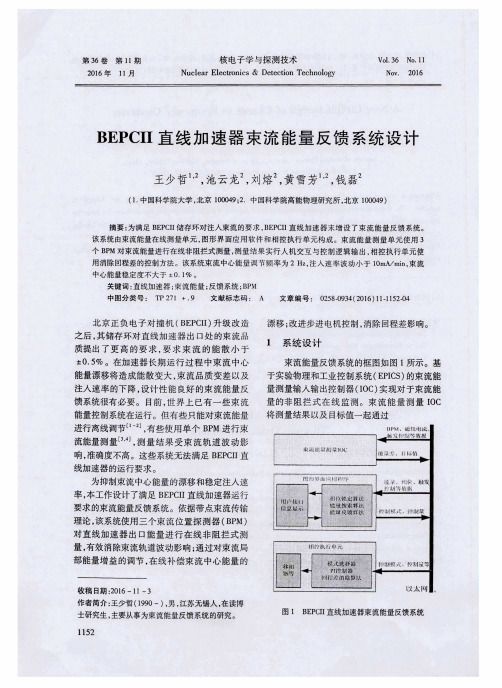
·粒子束及加速器技术·BEPCII 直线加速器数字延时触发器的设计与实现*杨 静1,2, 曹建社1,2, 杜垚垚1,2, 汪 林1, 马宇飞1,2, 张醒儿1,2,叶 强1, 麻惠洲1, 魏书军1, 岳军会1, 随艳峰1,2(1. 中国科学院 高能物理研究所,北京 100049; 2. 中国科学院大学,北京 100049) 摘 要: 针对北京正负电子对撞机II 期(BEPC II )直线加速器升级改造过程中束流位置探测器(BPM )电子学对外部触发信号的需求,设计了一台高精度延时控制、上升时间短和参数灵活调节的数字延时触发器。
采用FPGA (现场可编程门阵列)作为主控制器展开设计,重点介绍了基于FPGA 的边沿检测模块和多通道延时处理模块的设计与仿真,描述了FPGA 和驱动电路的设计方案以及在直线加速器上的应用。
经测试,延时可调范围4 ns ~4 μs ,最小步进4 ns ,步进误差0.125%;上升时间2 ns ,延时抖动135.4 ps 。
关键词: 直线加速器; 现场可编程门阵列; 可调延时; 上升时间; 多路扇出; 驱动电路中图分类号: TL506 文献标志码: A doi : 10.11884/HPLPB202032.200018Design and implementation of digital delay and pulse generatorof BEPC II linear acceleratorYang Jing 1,2, Cao Jianshe 1,2, Du Yaoyao 1,2, Wang Lin 1, Ma Yufei 1,2, Zhang Xing’er 1,2,Ye Qiang 1, Ma Huizhou 1, Wei Shujun 1, Yue Junhui 1, Sui Yanfeng 1,2(1. Institute of High Energy Physics , Chinese Academy of Sciences , Beijing 100049, China ;2. University of Chinese Academy of Sciences , Beijing 100049, China )Abstract : A digital delay and pulse generator with high precision delay control, short rise time and flexibleparameter adjustment is designed to meet the needs of BPM electronics for external trigger signals in the process ofupgrading the BEPC II linear accelerator. An FPGA is used as the main controller. This paper mainly introduces thedesign principle and simulation results of edge detection module and multi-channel delay processing module based onFPGA software platform, and describes the design of FPGA and drive circuit, and its application in linear accelerator.The test results show that the output pulse of the digital delay generator has an adjustable delay range of 4 ns ~4 μs, aminimum step of 4 ns, an adjustable error of 0.125%, a rise time of 2 ns, and a delay jitter of 135.4 ps.Key words : linear accelerator ; FPGA ; adjustable delay ; rise time ; multiple fan-out ; driver circuitBEPC II 装置稳定运行十余年,在高能物理研究过程中取得了很多重大物理研究成果,BEPC II 装置直线加速器能够为储存环提供更高能量的正负电子束流,实现全能量注入。

电子直线加速器的加速模式与运行参数分析电子直线加速器(linear accelerator,简称LINAC)是一种用于加速电子束的重要装置,广泛应用于医学、科研和工业领域。
本文将对电子直线加速器的加速模式与运行参数进行分析。
一、加速模式1. 连续波模式(CW):电子直线加速器在连续运行状态下工作,电子束连续不断地加速。
这种模式适用于高剂量率的医学放疗和高能量的科学研究。
2. 脉冲模式:电子束以脉冲方式加速,脉冲宽度较短。
这种模式适用于成像技术和脉冲放疗等应用。
3. 波前加速模式:电子束利用波前加速技术,采用相位引导结构对电子进行加速。
这种模式具有高效、紧凑和节能等优点,适用于工业应用和实验室研究。
二、运行参数1. 加速能量:电子直线加速器的加速能量是指电子束达到的能量,通常用兆电子伏(MeV)来表示。
不同的应用领域和需求,需要不同的加速能量。
例如,医学领域常用的医用直线加速器加速能量一般在6-25 MeV之间。
2. 加速器长度:电子直线加速器的长度决定了电子束加速的距离,同时也会影响加速器的成本和体积。
对于医学放疗来说,加速器长度一般在3-4米之间;而高能物理研究领域的大型电子直线加速器长度可达几公里。
3. 加速梯度:加速梯度是指电子直线加速器中电场的变化率,通常用兆电子伏/米(MV/m)来表示。
加速梯度越大,加速器的效率越高,但也会引起放电等问题。
目前,高梯度结构的研究与开发是电子直线加速器领域的一个热点。
4. 能量展宽:由于电子直线加速器中电子束的相对论效应,束团在加速过程中会出现能量展宽。
能量展宽会对加速过程的稳定性和束流质量产生影响。
因此,对于特定的应用需求,需要控制能量展宽在一定范围内。
5. 脉冲重复频率:脉冲模式下的电子直线加速器需要指定脉冲重复频率,即单位时间内脉冲的次数。
脉冲重复频率越高,意味着单位时间内可以进行更多的实验或治疗。
6. 稳定性要求:对于医学放疗等精密应用来说,电子直线加速器的稳定性非常关键。
30 1 2006 1HIGH ENERGY PHYSICS AND NUCLEAR PHYSICSVol.30,No.1Jan.,2006 BEPC Positron SourcePEI Guo-Xi1)SUN Yao-Lin LIU Jin-Tong CHI Yun-LongLIU Yu-Cheng LIU Nian-Zong(Institute of High Energy Physics,CAS,Beijing100049,China)Abstract BEPC —an upgrade project of the Beijing Electron Positron Collider(BEPC)is a factory type of e+e−collider.The fundamental requirements for its injector linac are the beam energy of1.89GeV for on-energy injection and a40mA positron beam current at the linac end with a low beam emittance of 1.6µm and a low energy spread of±0.5%so as to guarantee a higher injection rate( 50mA/min)to the storage ring.Since the positronflux is proportional to the primary electron beam power on the target,we will increase the electron gun current from4A to10A by using a new electron gun system and increase the primary electron energy from120MeV to240MeV.The positron source itself is an extremely important system for producing more positrons,including a positron converter target chamber,a12kAflux modulator, the7m focusing module with DC power supplies and the support.The new positron production linac from the electron gun to the positron source has been installed into the tunnel.In what follows,we will emphasize the positron source design,manufacture and tests.Key words positron source,flux concentrator,converter target,pulse power supply1IntroductionBEPC is the second phased construction of BEPC,working in the Tau-Charm energy region (2—5GeV).The design peak luminosity of1×1033cm−2·s−1at1.89GeV is two orders of magnitude higher than the present BEPC.To keep a higher av-erage luminosity,on-energy injection with a high in-jection rate of 50mA/min for e+beam is necessary, which is ten times the present value.The measures[1] we’re going to take include:1)increase the repetition rate from12.5Hz to50Hz;2)increase the bombarding electron energy from140MeV to240MeV;3)increase bombarding electron current from2.5A to6A and 4)manufacture a new positron source to increase the positron yield at the linac end from1.4%to2.7% e+/(e−×GeV).Table1shows the main parameters of the BEPC positron source.Table1.The main parameters of the BEPCe+source.2Positron converter assemblyThe BEPC positron source[2]is a conventional source.Electrons are accelerated to240MeV in the linac,and focused to a3mm to5mm diameter spot1 BEPC 6768 (HEP&NP) 301 BEPC 69References1PEI G X et al.Design Report of the BEPC Injector Linac:IHEP-BEPCII-SB-03-02.November20032GOU W P,PEI G X.HEP&NP,2002,26(3):279—285 (in Chinese)( , . ,2002,26(3):279—285) 3Kulikov A V et al.SLC Positron Source Pulsed Flux Con-centrator.Proceedings of1991IEEE Particle AcceleratorConference.San Francisco,1991.20054LIU J T et al.HEP&NP,2005,29(4):404(in Chinese) ( . ,2005,29(4):404)5Lamare J de,et al.SLC Positron Source Flux Concentrator Modulator.Proceedings of1991IEEE Particle Accelerator Conference.San Francisco,1991.31386Nam S H et al.Injection Kicker Modulator in2GeV Pohang Light Source.Proceedings of1998Twenty Third Interna-tional Power Modulator Symposium70 (HEP&NP) 302005–05–13 ,2005–07–081)E-mail:peigx@。
BEPCⅡ直线加速器相控系统设计研制的开题报告一、项目背景BEPCⅡ直线加速器是我国第二代储存环加速器,在其注入器上需要使用直线加速器将电子束的能量提高到储存环所需的能量。
本项目旨在设计研制BEPCⅡ直线加速器相控系统,以控制加速器中的电子束流的相位和能量。
二、项目目标设计研制BEPCⅡ直线加速器相控系统,以控制加速器中的电子束流的相位和能量,实现加速器中电子束的稳定加速。
三、技术路线1. 采用数字信号处理芯片FPGA设计相控系统,实现快速控制和高精度稳定性;2. 采用数字PⅢ控制系统,实现精密的电子束流控制;3. 采用低噪音、高精度的DDS芯片实现信号合成功能;4. 通过数据传输和处理系统,实现相控器与上位机的通讯和数据处理功能。
四、主要内容和技术难点1. 相控系统硬件设计:包括FPGA设计、时钟设计、接口设计等;2. 相控系统软件设计:包括相位控制算法设计、相位调制算法设计、参数设置等;3. 数据传输和处理系统设计:包括数据传输协议、数据处理方式等;4. 软硬相结合测试:进行软硬件相结合测试,测试系统的稳定性和可靠性;5. 解决系统中可能出现的故障及问题。
五、预期成果成功设计研制出BEPCⅡ直线加速器相控系统,并通过测试验证系统的可靠性和稳定性,在加速器运行中实现电子束流的精密控制和稳定加速。
六、项目计划1. 项目启动时间:2021年7月;2. 项目预计周期:12个月;3. 第1-3个月:进行需求分析、方案设计和技术选型等;4. 第4-8个月:进行系统的硬件和软件设计及制作,完成系统的初步调试;5. 第9-10个月:进行系统的测试和优化,并解决可能出现的故障及问题;6. 第11个月:完成系统的一次验收;7. 第12个月:进行系统的最终测试和调试,提交验收报告。
七、项目成本项目总成本:200万元,其中硬件成本150万元,软件开发成本30万元,测试成本20万元。
八、风险预测及控制1. 设备研制周期和成本风险:通过合理的计划和风险管理机制,提高研制效率和控制成本;2. 技术风险:通过技术攻关和验收保证系统的技术水平;3. 经济风险:通过预算控制成本,并及时调整预算以适应实际情况;4. 交付风险:制定完善的交付计划,确保项目按时交付。
第19卷 第9期强激光与粒子束Vol.19,No.9 2007年9月H IGH POWER L ASER AND PAR TICL E B EAMS Sep.,2007 Article ID: 100124322(2007)0921537206Two2pulse acceleration for BEPCⅡinjector linac3PEI Shi2lun, WAN G Shu2hong, L IU Wei2bin(I nstit ute of Hi gh Energy Physics,Chinese A cadem y of S ciences,P.O.B ox91828,Bei j ing100049,China) Abstract: In order to double the injection rate of positron beam from the linac to the storage ring of B EPCⅡ,a two2pulse generation and acceleration scheme has been proposed.The two2pulse simulation by programsincluding L IAR,PARM EL A,EGUN and TRANSPOR T is described first and the method is applied in thebeam dynamics studies of B EPCⅡlinac.The experiment of two2pulse acceleration was performed in B EPCⅡlinac and some preliminary results are obtained,which provides a good reference for f urther upgrading of B EPCⅡinjector linac. K ey w ords: Two2pulse; B EPCⅡlinac; Beam dynamics; Numerical simulation C LC number: TL501; TL53 Document code: A In order to double t he posit ron injection rate fro m t he linac to t he storage ring,a two2p ulse acceleration scheme(two macro beam p ulses wit h a time interval of56.02ns)has been p roposed[1]for f urt her up grading of B EPCⅡinjector linac.At t he p resent bunching system exit of B EPCⅡlinac,at least five bunches in one macro beam p ulse are p roduced[2],accordingly,no less t han ten bunches need to be cont rolled in t he real two2p ulse acceleration mode,which makes it difficult to get t he best beam characteristics.Wit h t he adoption of a new bunching system wit h two sub2harmo nic bunchers(SHBs)[3]in B EPCⅡlinac,only a single bunch wit h higher bunch charge and better beam characteristics in one macro beam p ulse is obtained at t he exit of t he bunching system,which facilitates t he real operation of two2p ulse mode.1 Tw o2pulse generation and acceleration In t he new bunching system,two SHBs are int roduced to replace t he2.856GHz standing wave p re2 buncher.The generation and acceleration of t he two2p ulse beams after adoption of t he sub2harmonic bunc2 hing system is schematically illust rated in Fig.1,t here is o nly a single bunch in one macro beam p ulse.Fig.1 Two2pulse generation and acceleration2 Simulations Up to now,it is hard to find a single p rogram to simulate t he beam dynamics of t he whole elect ron linac including t he gun,t he bunching system and t he accelerating sections,it is even harder to st udy t he beam dy2 namics of two2p ulse acceleration wit h a single program.In order to provide reference for B EPCⅡlinac up gra2 ding p roject,several programs including EGUN,PARM EL A,L IAR and TRANSPOR T are adopted to simu2 late t he beam dynamics of t he two2p ulse acceleratio n.3R eceived d ate:2007203212; R evised d ate:2007206220Found ation item:Supported by BEPCⅡupgrading projectBiography:Pei shilun(1979—),male,born at Xinji city of Hebei province,graduated from t he Institute of High Energy Physics,assistant researcher,studies accelerator physics and it s applications;peisl@。
2.1 Modif ications of L IAR In our simulation st udies ,t he IH EP version of p rogram L IA R 1.9[425]is used to simulate t he beam dy 2namics at t he downst ream of t he bunching system and evaluate t he beam characteristics at t he linac exit.Since t he multi 2bunch energy spread calculation met hod and t he int roducing met hod of long range wakefield in L IAR 1.9can not be directly used in simulation ,source code modifications of L IA R 1.9have been done as follows : (1)In L IA R 1.9,t he multi 2bunch energy sp read is usually written asΔE total =∑n Q n∑i q ni E 2ni Q n-∑i q ni E ni Q n 21/2∑n Q n (1)where ΔE total is t he total energy spread of t he p ulse ,Q n is t he total charge of bunch n in t he p ulse ,q ni and E ni are t he charge and energy of macro particle i in bunch n respectively.Essentially ,t he calculated energy sp read by Eq.(1)is still t he energy spread of o ne single bunch ,which can not reflect t he energy spread in 2crease caused by t he energy difference between two bunches.To evaluate t he multi 2bunch energy sp read p roperly ,a new equation has been appliedΔE total =∑n ∑i q ni E 2ni ∑n Q n -∑n ∑i q ni E ni ∑n Q n 21/2(2) (2)When long range wakefield is introduced in t he beam dynamics simulation of one p ulse wit h program L IAR 1.9,o nly t he wakefield effect of bunch n on bunch n +1is considered ,while t hat of bunch n on bunch n +2and t he ot her downst ream bunches is not considered.In order to investigate t he effect of long range wakefield more generally ,long range wakefield effect in L IA R 1.9has been modified to take into account t he wakefield effect of bunch n on all t he downst ream bunches.2.2 Simulation method To find an app rop riate met hod to simulate t he beam dynamics of two 2p ulse acceleration wit h one or more bunches in one p ulse in t he whole linac ,t he following met hods are applied : (1)Program EGUN [6]is used to simulate t he beam optics in t he elect ron gun.Correspondingly ,t he t ransverse beam parameters including t he emittance and t he twiss parameters at t he elect ron gun exit ,which will be used as t he initial beam parameters of PARM EL A [7],are obtained. (2)Wit h p rogram PARM EL A ,t he beam dynamics of t he bunching p rocess is simulated and optimized ,t hen t he beam parameters including t he emittance ,t he bunch charge ,t he twiss parameters ,t he beam energy and t he beam energy sp read at t he bunching system exit are acquired. (3)When t he relativistic velocity of elect ron beams is almo st equal to 1,t he space charge effect can be neglected ,t hus p rogram TRANSPOR T optimizes t he beam optics from t he bunching system exit to t he linac exit.The beam parameters calculated by PARM EL A serve as t he inp ut beam parameters of code TRANS 2POR T [8]in simulating and optimizing t he lattice from t he bunching system exit to t he lianc end ,finally beam optics wit h t he optimized lattice is achieved. (4)In high energy linacs ,wakefield is t he main effect on t he beam characteristics.In addition ,t he beam p ulse interval in t he two 2p ulse mode is usually at t he level of nanosecond ,and t he wakefield of t he first p ulse will affect t he second p ulse.Consequently ,t he wake potential ,especially t he long range wake potential in t he accelerating st ruct ures should be calculated before simulating t he two 2p ulse acceleration.Analytical met hods and comp uter codes such as ABCI [9],MA FIA [10]and so on can be used to calculate t he wake poten 2tial.For simulation of t he two 2p ulse acceleratio n in B EPC Ⅱlinac ,t he wake potential is estimated p recisely wit h t he met hod in Ref.[11]. (5)In addition to t he beam parameters at t he bunching system exit ,t he wake potential in t he accelera 28351强激光与粒子束第19卷ting st ruct ures and t he beam optics wit h t he optimized lattice are all obtained,t he beam dynamics of t he two2 p ulse acceleration at t he downst ream of t he bunching system is simulated wit h t he modified IH EP version of L IAR1.9.In t he st udies of t he two2p ulse acceleration wit h L IAR,if t here is only one single bunch in one macro beam p ulse,which is t he case of B EPCⅡlinac wit h SHBs,L IAR can be directly used.However,for st udies of two2p ulse acceleration for B EPCⅡlinac wit hout SHBs,t he simulation p rocess is divided into t hree step s:a)The simulation of one p ulse can be done wit h L IAR directly[12];b)If one p ulse is regarded as a large macro bunch wit h t he total charge of t he bunches in t he p ulse t he two p ulses can be regarded as two large macro bunches,t hen t he simulation of t he two large macro bunches can be performed by L IA R;c)Af2 ter t he simulations of one bunch and two large macro bunches,t he total beam characteristics dilution of t he two2p ulse caused by any kind of error or jitter effect s[13]can be summed up as followsΔtotal=Δ2one_pulse+Δ2two_macro_bunches(3) whereΔtotal is t he total beam characteristics dilution such as emittance,energy spread and so on,Δone_pulse andΔtwo_macro_bunches are t he beam characteristics dilutions caused by error or jitter effect s on t he one p ulse and t he two large macro bunches respectively. It is wort h noting t hat t he effect of t he first beam p ulse on t he seco nd beam p ulse in t he bunching p rocess is neglected in our met hod,since t he energy and t he p ulse charge differences caused by beam loading in standing wave cavities[14]and t he wakefield for particle beams wit hβ≤1[15]are relatively small,and can bef urt her mitigated to a very low level by adjusting t he gun grid p ulser voltage and t he beam p ulse timing re2spectively[16].2.3 Simulation results Wit h our met hod,t he beam dynamics of two2p ulse acceleration for2A(averaged current)/3.2A(peak current)elect ron beam in B EPCⅡLinac wit h/wit hout SHBs has been st udied systematically.Table1shows t he beam characteristics parameters calculated wit h EGUN and PARM EL A at t he gun exit and t he bunching system exit for B EPCⅡpre2injector wit h/wit ho ut SHBs[3].Fig.2shows t he linearly approximated beam op2 tics downst ream of t he bunching system optimized by TRANSPOR T wit hout considering any wakefield effect s and any kind of error or jitter effect s.Table2shows t he final beam characteristics simulation result s at B EPCⅡlinac wit h/wit hout SHBs exit for t he beam dynamics of two2p ulse acceleration when0.3mm ini2 tial beam off set,0.2mm accelerating st ruct ure and quadruple misalignment,±2°accelerating p hase drift and ±0.1%modulator’s high voltage jitter were employed.In addition,in order to compensate t he bunch ener2 gy spread caused by short range wakefield,t he accelerating p hase was optimized,i.e.,t he bunch center was p ut off2crest of t he accelerating wave,so t hat t he particles in t he tail and head part s would have higher and lower energy gain,respectively[12].T able1 B eam ch aracteristics calculated with EGUN and PARME LA at electron gun exit and bunching system exit for2A electron beam gun exit bunching system exit parameter without SHBs with SHBs parameter with SHBs without SHBsenergy/keV150energy/MeV56.1953.39 intensity/(nC/pulse) 3.2energy spread(±5p s)/MeV±3.58±3.70pulse width(bottom)/ns 1.6intensity(±15p s)/(nC/pulse) 2.56 3.19pulse width(FW HM)/ns0.95bunch number in one pulse51emittance(2σ)/(mm2mrad)30.78intensity(±5ps)/(nC/bunch)0.16,0.563.10 0.71,0.56,0.18α 2.13pulse length(bottom)/ps>140010β/(m/rad)0.34bunch length(bottom)/ps1010γ/(rad/m)16.45bunch interval/p s350emittance(1σ)/(mm2mrad) 1.18 1.05α-0.120.06β/(m/rad) 1.50 1.129351No.9Pei Shilun,et al:Studies on two2pulse acceleration for B EPCⅡinjector linacFig.2 Linearly approximated beam optics downstream of t he bunching system for BEPC ⅡlinacT able 2 Simulation results at BEPC ⅡLinac exit with/without SHBs of t w o 2pulse acceleration beam dynamics for 2A electron beam without SHBs with SHBs single pulsetwo pulses single bunch two bunches bunch length (bottom )/ps 10 10pulse length (bottom )/ps >1400 10intensity (±15p s )/(nC/pulse ) <2.56 <3.19intensity (±5ps )/(nC/bunch ) <0.16,<0.56,<0.71,<0.56,<0.18 <3.10energy spread (±5ps )/%±(0.71±0.06)±(0.77±0.06)±(0.53±0.06)±(0.63±0.06)emittance (1σ,no correction )/(mm ・mrad )0.11±0.040.16±0.040.32±0.040.43±0.04emittance (1σ,correction )/(mm ・mrad )0.05±0.020.05±0.020.11±0.020.13±0.02 Analyzing Table 1and Table 2gives t he following conclusions : (1)The replacement of bunching system wit ho ut SHBs by t hat wit h SHBs can reduce t he number of bunches in one macro beam p ulse ,which can facilitate t he operation of t he two 2p ulse acceleration. (2)For t he 2A elect ron beam ,t he adoption of a two 2p ulse acceleration scheme will result in a small en 2ergy spread increase and a large emittance dilution at t he linac exit.While wit h t he employment of an effec 2tive beam orbit correction scheme [17],t he emittance dilution can be cont rolled to an intermediate level ,which can meet t he requirement of t he storage ring for t he elect ron beam [1]. (3)Alt ho ugh t he beam energy sp read of t he 2A beam at t he linac exit becomes smaller for B EPC Ⅱlinac wit h SHBs ,t he effect of t he SHBs on t he energy sp read reduction is not obvious.In B EPC Ⅱinjector linac ,t he beam energy spread is mainly decided by t he bunch lengt h.Whet her t he SHBs is adopted or not ,t he bunch lengt h will be about 10p s ,i.e.,t he SHBs can not produce a bunch much shorter t han 10p s.If SHBs is adopted ,t he lo ng range wakefield effect on t he energy sp read in one p ulse can be wiped off ,but due to t he high bunching efficiency and t he bunch charge increase in one bunch ,t he short range wakefield effect on t he energy sp read will increase ,as a result ,t he effect of SHBs on t he beam energy spread at t he linac exit will not be obvio us. (4)The emittance at B EPC Ⅱlinac wit h SHBs exit is about 3times t hat at t he linac exit wit hout SHBs ,i.e.,t he SHBs have a negative effect on t he emittance of t he 2A beam ,which is mainly caused by t he opti 2mization of t he beam optics at t he downst ream of t he bunching system.If a better optimization met hod is em 2ployed ,t he negative effect might be relatively small.In t he calculation of beam optics by TRANSPOR T ,t he optimized lattice is obtained by linear app ro ximation and wit ho ut considering t he effect of t he beam charge (not space charge effect )on t he optics.In addition ,when t he optimized lattice is used as inp ut of L IAR ,t he higher t he charge contained in one bunch ,t he higher t he value of t he beam optics mismatch factor B mag ,hence t he mismatch factor for t he linac wit h SHBs will be higher t han t hat of t he Linac wit hout SHBs. Table 3shows t he simulation result s of 1A (averged current )electron beam when 0.9mm initial beam off set ,0.6mm accelerating st ruct ure and quadruple misalignment ,±2°accelerating p hase drift and ±0.1%modulator ’s high voltage jitter were employed ,according to t he alignment and real operation stat us of B EPC0451强激光与粒子束第19卷Ⅱlinac wit hout SHBs.Eit her linac wit h or wit hout SHBs can meet t he requirement of t he storage ring for t he elect ron beam [1]and has almost t he same energy spread and beam emittance at t he linac exit due to t he small difference between t he mismatch factors of t he beam optics ,while t he linac wit h SHBs has a shorter beam p ulse lengt h of 10p s rat her t han a lengt h longer t han 1.4ns and higher beam current at B EPC Ⅱlinac exit.T able 3 Simulation results at BEPC ⅡLinac exit with/without SHBs of the t w o 2pulse acceleration beam dynamics for 1A electron beam without SHBs with SHBs single pulsetwo pulses single bunch two bunches bunch length (bottom )/ps 10 10pulse length (bottom )/ps >1400 10intensity (±15p s )/(nC/pulse ) <1.30 <1.52intensity (±5ps )/(nC/bunch ) <0.07,<0.35,<0.45,<0.35,<0.08 <1.43energy spread (±5ps )/%±(0.65±0.03)±(0.67±0.03)±(0.59±0.03)±(0.61±0.03)emittance (1σ,no correction )/(mm ・mrad )0.09±0.020.12±0.020.14±0.020.16±0.02emittance (1σ,correction )/(mm ・mrad )0.04±0.010.04±0.010.03±0.010.03±0.01 Comparing Table 2and Table 3,it is found t hat t he lower t he beam current ,t he better t he beam charac 2teristics at t he linac exit ,t he smaller t he beam characteristics difference between t he single 2p ulse and t he two 2p ulse operation modes ,t he loo ser t he alignment tolerance of t he component s in t he accelerator.It also p roves t hat it is better to use lower beam current to get a better beam characteristics for t he electron injection mode in t he real operation of B EPC Ⅱlinac wit hout SHBs.3 ExperimentsFig.3 Signals of BCT8to BCT11on t he oscilloscope Two 2p ulse generation and acceleration experiment wasperformed in B EPC Ⅱlinac wit hout SHBs ,and t here were atleast 5bunches in one p ulse and 10bunches in two p ulses.Fig.3shows a typical waveform of t he final four beam currentmonitors (BC T8to BCT11)for t he two 2p ulse accelerationmode.The time interval between t he two p ulses was 56.02nsand was adjusted wit h a step of 20p s.BC T11was placed att he linac end.The amplit udes of BCT11for t he two p ulseswere 33mV and 40mV ,corresponding to about 500mA and 600mA beam peak current respectively.It is known t hat if t he initial current s of t he two beam p ulses have t he same value ,at t he linac end t he current of t he second p ulse should be lower t han t hat of t he first p ulse [14],but in our experiment it is just t he oppo site ,which was caused by different grid p ulser voltages at t he elect ron gun.For t he first p ulse ,t he p ulser voltage was 271.8V ,corresponding to an initial averaged current of 1.1A ,while for t he second p ulse t he voltage and current were 282.1V and 1.3A ,respectively. The beam emittance was measured for bot h single 2p ulse and two 2p ulse operation modes ,and t he meas 2urement s were done by t he Q 2scan met hod [18]at t he linac end.For t he single 2p ulse mode ,t he measured hori 2zontal and vertical emittances are about 0.082±0.010(mm ・mrad )and 0.096±0.017(mm ・mrad )respec 2tively ,while t hey are about 0.086±0.011(mm ・mrad )and 0.141±0.036(mm ・mrad )for t he two 2p ulse mode.The measured vertical emittance is larger t han t he horizontal emittance for bot h operation modes ,which is caused by different beam optics matching stat us in t he two paring t he measured em 2mitances wit h t he simulated ones in Table 3for 1A elect ron beam ,it can be found t hat t hey are consistent on t he whole.In addition ,t here is a small difference between t he emittance of t he single 2p ulse mode and t hat of t he two 2p ulse mode ,and t he beam characteristics of t he two modes will have a small difference for a beam current lower t han 1A (averaged ).The po sit ron beam (who se current is much lower t han 1A )injection rate1451No.9Pei Shilun ,et al :Studies on two 2pulse acceleration for B EPC Ⅱinjector linac2451强激光与粒子束第19卷can be finally increased and doubled by adoption of t he new SHBs and t he two2p ulse acceleration scheme.4 Conclusion In order to p rovide reference for f urt her up grading of B EPCⅡinjector linac,beam dynamics of two2 p ulse acceleration has been st udied,a two2p ulse experiment has been performed,some p reliminary result s are obtained.Alt ho ugh t here is still some difference between t he simulation and measurement result s,t hey are consistent on t he whole.In additio n,it is indicated t hat t he adoption of t he two2p ulse scheme is not for elec2 t ron injection,but for t he doubling and increasing of t he p rimary elect ron beam charge to increase t he po si2 t ron yield and t he position injection rate to t he ring.In B EPCⅡinjector linac,t he charge contained in t he po sit ron bunch is much smaller t han t hat in t he elect ron bunch.In addition,t he beam characteristics of t he p rimary elect ron beam wit h SHBs is better t han t hat wit hout SHBs,which can be known f rom t he better beam characteristics at t he SHBs exit and t he negligible wakefield effect along t he12m long beam orbit be2 tween t he bunching system exit and t he posit ron target.In conclusion,t he adoption of SHBs can enhance t he po sit ron beam performance at t he linac exit and facilitate t he real operation of t he two2p ulse mode.R eferences:[1] Pei G X,Wang S H,Chi Y L,et al.Preliminary design report of B EPCⅡ2linac[R].IH EP2B EPCⅡ2SB203,2002.[2] Pei S L.Studies on two2bunch acceleration in electron linear accelerator[D].Beijing:IH EP,2006.[3] Pei S L.Physical design of t he sub2harmonic bunching system[R].Beijing:IH EP,2006.[4] Zhou Z S.Studies on t he optimum beam orbit correction for high energy electron linacs[D].Hefei:Anhui University,2003.[5] Assmann R.A computer program for modeling and simulation of high prformance linacs[CP].SLAC/AP21003,1997.[6] Herrmannsfeldt W B.Egun2an electron optics and gun design program[CP].SLAC2331,1998.[7] Y ound L M,Billen J H.Parmela[CP].LA2U R29621835,2002.[8] Carey D C et al.TRANSPOR T2a computer program for designing charged particle t ransport systems[CP].SLAC2R2530,1998.[9] Chin Y er’s guide for ABCI(Version8.7)[CP].CERN SL/94202(AP),1994.[10] The MA FIA collaboration.MA FIA user manual(Version4.106)[CP].CST Inc,2000.[11] Pei S L,Wang S H.Wakefield calculation studies in constant gradient accelerating structures[J].Hi gh Energ y Physics and N uclearPhysics,2006,30(3):2512259.[12] Wang S H,Gu P D,Liu W B,et al.Wakefield effect s on t he BEPCⅡinjector linac[J].Hi gh Energ y Physics and N uclear Physics,2004,28(6):6532658.[13] Wang S H,Gu P D,Liu W B,et al.Error and jitter effect s on BEPCⅡ2linac[J].Hi gh Power L aser and Particle B eams,2005,17(2):2582262.[14] Pei S L,Wang S H.Transient beam loading effect s in standing wave cavities of linear accelerators[J].Hi gh Energ y Physics and N uclearPhysics,2006,30(5):4542461.[15] Gao J.Analytical formulae for t he wakefields produced by t he nonrelativistic charged particles in periodic disk2loaded st ructures[J].N uclInst r and Met h,2000,A447(3):3012308.[16] Ohsawa S,Liu W B,Pei S L.Summary of gun and bunching system[R].Beijing:IH EP,2003.[17] Wang S H,Gu P D,et al.Studies on optimizing beam optics and orbit correction for BEPCⅡ2Linac[J].Hi gh Energ y Physics and N uclearPhysics,2003,27(02):1732177.[18] Wang S H,Ye Q,Cao J S,et al.Emittance measurement by multi2changing focusing strengt h[J].Hi gh Energ y Physics and N uclearPhysics,2002,26(11):118421188.BEPCⅡ直线加速器的双脉冲加速研究裴士伦, 王书鸿, 刘渭滨(中国科学院高能物理研究所,北京100049) 摘 要: 为了将B EPCⅡ直线加速器的正电子注入速率提高到单脉冲运行时的两倍左右,提出了双脉冲产生和加速的方案。