Series Elastic Actuators for legged robots
- 格式:pdf
- 大小:750.54 KB
- 文档页数:10
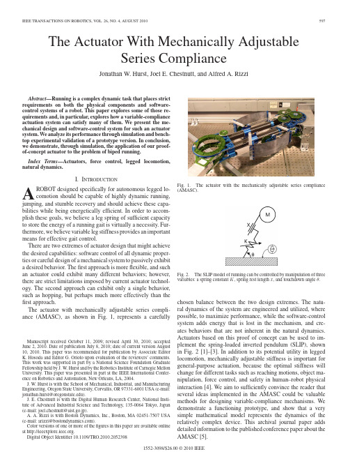
The Actuator With Mechanically AdjustableSeries ComplianceJonathan W.Hurst,Joel E.Chestnutt,and Alfred A.RizziAbstract—Running is a complex dynamic task that places strict requirements on both the physical components and software-control systems of a robot.This paper explores some of those re-quirements and,in particular,explores how a variable-compliance actuation system can satisfy many of them.We present the me-chanical design and software-control system for such an actuator system.We analyze its performance through simulation and bench-top experimental validation of a prototype version.In conclusion, we demonstrate,through simulation,the application of our proof-of-concept actuator to the problem of biped running.Index Terms—Actuators,force control,legged locomotion, natural dynamics.I.I NTRODUCTIONA ROBOT designed specifically for autonomous legged lo-comotion should be capable of highly dynamic running, jumping,and stumble recovery and should achieve these capa-bilities while being energetically efficient.In order to accom-plish these goals,we believe a leg spring of sufficient capacity to store the energy of a running gait is virtually a necessity.Fur-thermore,we believe variable leg stiffness provides an important means for effective gait control.There are two extremes of actuator design that might achieve the desired capabilities:software control of all dynamic proper-ties or careful design of a mechanical system to passively exhibit a desired behavior.Thefirst approach is moreflexible,and such an actuator could exhibit many different behaviors;however, there are strict limitations imposed by current actuator technol-ogy.The second approach can exhibit only a single behavior, such as hopping,but perhaps much more effectively than the first approach.The actuator with mechanically adjustable series compli-ance(AMASC),as shown in Fig.1,represents a carefullyManuscript received October11,2009;revised April30,2010;accepted June2,2010.Date of publication July8,2010;date of current version August 10,2010.This paper was recommended for publication by Associate Editor K.Hosoda and Editor G.Oriolo upon evaluation of the reviewers’comments. This work was supported in part by a National Science Foundation Graduate Fellowship held by J.W.Hurst and by the Robotics Institute of Carnegie Mellon University.This paper was presented in part at the IEEE International Confer-ence on Robotics and Automation,New Orleans,LA,2004.J.W.Hurst is with the School of Mechanical,Industrial,and Manufacturing Engineering,Oregon State University,Corvallis,OR97331-6001USA(e-mail: jonathan.hurst@).J.E.Chestnutt is with the Digital Human Research Center,National Insti-tute of Advanced Industrial Science and Technology,135-0064Tokyo,Japan (e-mail:joel.chestnutt@aist.go.jp).A.A.Rizzi is with Boston Dynamics,Inc.,Boston,MA02451-7507USA (e-mail:arizzi@).Color versions of one or more of thefigures in this paper are available online at .Digital Object Identifier10.1109/TRO.2010.2052398Fig.1.The actuator with the mechanically adjustable series compliance(AMASC).Fig.2.The SLIP model of running can be controlled by manipulation of threevariables:a spring constant K,spring rest length x,and touchdown angleθ.chosen balance between the two design extremes.The natu-ral dynamics of the system are engineered and utilized,wherepossible,to maximize performance,while the software-controlsystem adds energy that is lost in the mechanism,and cre-ates behaviors that are not inherent in the natural dynamics.Actuators based on this proof of concept can be used to im-plement the spring-loaded inverted pendulum(SLIP),shownin Fig.2[1]–[3].In addition to its potential utility in leggedlocomotion,mechanically adjustable stiffness is important forgeneral-purpose actuation,because the optimal stiffness willchange for different tasks such as reaching motions,object ma-nipulation,force control,and safety in human–robot physicalinteraction[4].We aim to sufficiently convince the reader thatseveral ideas implemented in the AMASC could be valuablemethods for designing variable-compliance mechanisms.Wedemonstrate a functioning prototype,and show that a verysimple mathematical model represents the dynamics of therelatively complex device.This archival journal paper addsdetailed information to the published conference paper about theAMASC[5].1552-3098/$26.00©2010IEEEII.B ACKGROUNDMost research papers that analyze the mechanics of running base this analysis on some form of the SLIP model,as shown in Fig.2.This model can be used to describe the motion of the center of mass of a running animal[6],[7]or a running robot. The basic definition of running[8]is linked to the SLIP idea—energy is transferred from kinetic and gravitational potential energy in theflight phase to spring energy in the stance phase, and vice versa.pliance and RunningPhysical series compliance is virtually necessary to achieve a robust,energetically economic running gait.Simulating compli-ance using a rigid actuator,such as an electric gearmotor,is not practical for three reasons:bandwidth limitations,power-output limitations,and energetic efficiency.For a realistic example, imagine a pogo stick that uses a gearmotor,power electronics, and batteries in place of the coil spring.To achieve the power output of the coil spring,a very large motor would be required, thereby adding significant weight to the pogo stick.If the power demands could be met,then the device would not last long be-fore running out of batteries,because the electric system is much less efficient at storing and releasing energy than a mechanical spring.The bandwidth limitation of an electric motor is due,in large part,to the high reflected inertia that is linked rigidly to the robot leg.Electric motors must be significantly geared to pro-vide useful torque for robotics applications,and the reflected inertia of the rotor is amplified by the square of the gear re-duction.The reflected inertia can be larger than the inertia of the entire robot,making a correct dynamic response to impacts impossible.Upon impact with the ground,the stationary mo-tor instantaneously matches speed with the moving mass of the robot,thereby causing a large force spike and a loss of energy in the inelastic collision.Even with instantaneous sensing and computation,the torque required to accelerate the motor in-stantly to match the ground speed during an unexpected impact will exceed the motor’s torque limit.Despite the drawbacks, some legged robots use this approach for running gaits,includ-ing Honda’s Asimo[9].We believe that the energetic economy and robustness to disturbances could be dramatically improved through the appropriate use of series compliance.Passive series springs can alleviate many of the problems that are inherent in direct actuation schemes for locomotion.They can be used for energy storage,power transmission,or a combi-nation of the two,as illustrated in Fig.3.A physical spring has arbitrarily high power density,depending on its stiffness,but with bounded energy density.Motors and batteries have rela-tively low power density in comparison but have a much higher energy density per unit mass,thereby making a compelling ar-gument for combining the two systems in a series combination. The spring can absorb and output energy at high power,while the motor can add and remove energy as needed,without handling all of the power transferred in a running gait.Springs are particularly useful in rhythmic systems,because energy can be stored and released much more efficientlythrough Fig.3.In a series spring system,energy can be transmitted through the spring if it does not compress,or energy can be stored and released from the spring as it deflects.For a cyclic system,such as a running gait,most of the energy can be stored and returned with each stride,thereby eliminating the energy transfer and losses through the rest of the transmission.a spring than if it were passed through the motor,transmission, and power electronics with each transfer.Not only do physical springs reduce wasted energy with each stride,but they also significantly reduce the necessary size and weight of many of the motor and transmission components.Minimizing weight reduces the total amount of energy that needs to be transferred with each stride.Animals make use of physical springs in their running gait,most likely for these reasons and more[10],[11].B.Physically Variable Compliance as a Method of Control While physical compliance is virtually a necessity for suc-cessful running,varying the compliance provides a useful tool for gait control.Research has shown that animals can adjust leg stiffness and vary it to control running and hopping in certain situations[12]–[14].The normal steady-state motion of a SLIP-based running gait can be described by three parameters.In Schwind and Koditschek’s mathematical analysis,leg length and angular ve-locity at the bottom of the stance,along with the leg stiffness, were chosen[1].Control of forward speed,stance duration,and flight duration was demonstrated experimentally in Hodgins and Raibert’s work with running robots[15].Another choice might be leg stiffness,hopping height,and stride length;there are many possible three-variable parameterizations that could be consid-ered.Because the SLIP model has only three terms available to control the three parameters of a running gait,the absence of one term may limit the control choices,and certain disturbances to the SLIP-model running gait may not be controllable.For example,if a SLIP runs over terrain that varies in stiffness,the leg stiffness must change or the running gait will be altered. Most research suggests that animals prefer to maintain leg stiffness over a range of running speeds;however,they do change leg stiffness when other methods of control are not available[3],[16]–[18].For example,hopping or running on a surface of changing stiffness[6],[12],[16],hopping in place with varying frequency[6],[12],or running at different speeds with constant stride length[17].C.Actuator DesignResearchers at the Massachusetts Institute of Technology (MIT)did pioneering work in thefield of compliant actuation with the development of the series elastic actuator(MIT-SEA)HURST et al.:ACTUATOR WITH MECHANICALLY ADJUSTABLE SERIES COMPLIANCE599[19].Different implementations of the device used both electric and hydraulic power,with similar results.The MIT-SEA was developed as a force actuator for robot arms,and the design was later refined and used on several walking robots[20]–[23]. The springs on the MIT-SEA are essentially acting as a force sensor for the low-level controller,like a soft load cell. Several mechanisms have been developed with variable se-ries compliance,with varying configurations[24].Some are designed for manufacturing or manipulation tasks involving constrained contact or impacts,which benefit from the high bandwidth of passive dynamics[25]–[29],while others are re-search platforms to explore biomimetic control of joint stiffness and position[30]–[32].One drawback to most of these mecha-nisms is that they rely on two antagonistic motors,cocontracting nonlinear springs to change the stiffness of a driven joint.As in animals,this cocontraction uses energy,because the motors must apply force to compress the springs and hold a particu-lar stiffness value.Some mechanisms use a leaf spring that is shortened or lengthened to adjust the stiffness,which avoids the energy inefficiency of antagonistic motors.Others rely on an adjustable mechanical advantage to change stiffness,but cannot control the stiffness function[33].Most of these examples are designed for purposes other than legged locomotion and incor-porate small springs that can store very little energy relative to that required of a running gait.Pneumatic actuators are inherently springy and can store plenty of energy,which has led to their successful use on several running and hopping robots[34].Pneumatic actuators used in antagonistic pairs have also been used to control the passive compliance of an actuated joint,thereby leading to moderate success in bipedal locomotion[35].However,pneumatic actu-ators are also inherently difficult to control,energetically lossy, and difficult to power without an external compressor.Electri-cal actuation allows for much more precise control and allows for easier tether-free operation.For these reasons,we chose to use electric actuation,although the ideas presented in this paper could be implemented with some other form of actuation. Mechanically adjustable series compliance may also be use-ful for control stability.Several researchers have shown that certain types of physical compliance are important for force control[36]–[38];it is intuitive that a very low-stiffness joint is more capable of applying a constant force in the face of position disturbances than a rigid joint[4].For good position control,higher stiffness improves disturbance rejection,and hu-mans maximize their arm stiffness to hold a specific position. However,high stiffness combined with neural delay can lead to instabilities such as increased hand tremor[39].Humans choose specific arm stiffnesses to stabilize different dynamic motions and to accommodate different reaching motions,likely choosing between disturbance rejection and control stability[40],[41].III.A CTUATOR W ITH M ECHANICALLY A DJUSTABLES ERIES-C OMPLIANCE D ESIGNThe natural dynamics of a system are an inseparable part of its behavior.The mechanical design,which determines the natural dynamics of a system,is thus an essential part ofthe Fig.4.Mechanical model of the physical actuator.TABLE ID EFINITIONS OF S YMBOLS D ESCRIBING THEAMASCoverall control system design.The actuator presented here is an integrated mechanism and software controller,with mechanical design choices made to closely match the dynamic behavior of a simple,understandable,controllable mechanical model, as illustrated in Fig.4.By designing the mechanism for this purpose,the control system is dramatically simplified over using a very complex mathematical model.Throughout the remainder of this paper,we will use the notational conventions of Table I. The AMASC is essentially a single compliant joint,which most closely resembles a knee,endowed with engineered natu-ral dynamics.There are two degrees of freedom with two corre-sponding motors.In addition,there are two identical opposing springs,much like antagonistic muscles in animals.One motor controls the spring pretension,thereby stretching both springs, which is represented by x3in Fig.4.This degree of freedom is analogous to muscle cocontraction in animals.The knee joint does not move as a result of changes to x3,but its rotational stiff-ness changes,thereby allowing the actuator to tune the stiffness of the natural dynamics.The other motor controls the spring rest position,θ1,which is used as the primary energy source and controls any motions not described by the system’s natural dynamics.These two motor-controlled parameters,along with the leg angle at touchdown,provide all three parameters for control of a SLIP-model robot.600IEEE TRANSACTIONS ON ROBOTICS,VOL.26,NO.4,AUGUST2010Fig.5.Cable-routing diagram of the AMASC.J1and J2are pinned in place but can rotate freely;the spiral pulleys are also pinned in place but are free to rotate.The remaining four pulleys arefloating and can move sideways as well as rotate.For notation descriptions,see Table I.A.Mechanical DesignMany of the mechanism design challenges are common ones; for example,minimizing friction,backlash,mass,and inertia. Several specific choices were made that influence each of these attributes,such as the location and type of speed reduction, choice of materials,and type of motor.Minimizing mass was a concern throughout the design process,because the AMASC was intended as a prototype leg for a bipedal robot with approx-imately1m leg length and30kg total mass.Of this30kg,20kg is reserved for motors,batteries,and computing.This allotment leaves only10kg for the entire framework and mechanism,in-cluding springs and power transmission.To minimize weight, all joints contain thin-section bearings,which are very light for a given load rating.All parts are machined aluminum,with the main structural members(analogous to the femur)made of thin-wall aluminum tube.The mass of this actuator proto-type is approximately4kg,and the dimensions are nearly50% oversized.In order to create a low-friction,zero-backlash system,the AMASC utilizes a high-speed cable drive[42].There is some stretch in the cable transmission,which adds series compliance to the system and is incorporated into the effective spring con-stant of our model.Because the cables are round,they may wrap around pulleys placed at any angle,unlike standard belts.This design freedom makes it easier to route cables through joints, thereby allowing the motors to be located remotely.Fig.5shows a diagrammatical representation of the cable routing,which il-lustrates the role of each motor in the tension of the two springs. Also shown is the fact that a displacement of the leg,θ2,results in displacement of the motor,θ1,displacement of the springs, or some combination of the two.There is a speed reduction between thefirst and second pulleys,which is not shown on the diagram;it is implemented using a combination of a block-and-tackle pulley mechanism and a difference in radii between r1 and r2.The speed reduction is physically located near the knee joint,but diagrammatically located near the motorθ1.In all of our representations,the speed reduction is shown solely as a difference between r1and r2.All friction related to the speed reduction is applied toθ1and corresponds to B1.The inertia of the speed reduction is added to the inertia of the motor and corresponds to J1.A speed reducer amplifies the motor inertia by the square of the speed reduction;this amplification appears in the relatively large values of J1.The transmission betweenθ2and the springs has very low friction and no speed reduction.Because the high-frequency behavior of the system is generally handled by the springs,low friction and inertia are most important in this part of the AMASC.The low-frequency behaviors of the system are handled by the motor,and thus,friction and inertia can be overcome by relatively low-bandwidth software compensation. Perhaps the most important aspect of the AMASC,along with the series spring,remotely located motors,and zero-backlash cable drive,is the physically variable series compliance.As stated in Section II,physical compliance is crucial for a running gait,while varying the compliance is a useful control strategy. The AMASC’s physical compliance resides in unidirectional fiberglass plates,which have a relatively high energy capacity on the order of1000J/kg.Varying the stiffness of the AMASC is achieved in much the same way as in animals,with cocontraction of opposing nonlinear springs.In the case of animals,the nonlinear spring is the muscle/tendon combination;in the case of the AMASC, the nonlinear spring is formed by afiberglass plate spring in series with a set of spiral pulleys.The reduction ratio of the pul-leys varies proportionally with thefiberglass spring deflection, to create some output spring function,such as F z(z)=Kz2. Placing two such spring functions in direct opposition results in a single effective spring-force function F eff.The resulting effective spring force is calculated by substituting(x3+∆x) and(x3−∆x)for z,where x3represents the pretension on the two nonlinear springs,and∆x represents the deflection from their rest position(x2−x1).Combining the two forces results inF eff(x3,∆x)=F z(x3+∆x)−F z(x3−∆x).(1) For the simple example of quadratic springs,F z(z)=Kz2F eff=K(x3+∆x)2−K(x3−∆x)2F eff=4Kx3(∆x).(2)In this manner,the stiffness of the resulting system can be changed by adjusting the pretension x3.Note that the pretension affects the force as much as the displacement∆x.The effective spring force F effis linear with respect to displacement(in this specific case),but its stiffness is now adjustable.In practice, the rate at which this parameter can be varied depends on the actuator and transmission used.Our prototype is intended for relatively slow changes at low force,such as during theflight phase of a running gait.The pulley function,G(z),is a design freedom and can be changed to impart a nearly arbitrary function to the spring/pulley system,F z(z).Logarithmic spiral pulleys were initially chosen because the spring function of the bendingfiberglass plates was unknown,because the desired spring function was unknown, and because two logarithmic spirals mesh correctly and provide the desired stiffening function[43].Our logarithmic spiral pul-leys,as diagrammed in Fig.6,are described by the followingHURST et al.:ACTUATOR WITH MECHANICALLY ADJUSTABLE SERIES COMPLIANCE601Fig.6.Logarithmic spiral pulleys used on the prototype AMASC.The spirals roll on each other as if they were gears,and the gray lines ending in arrows show the cables wrapped around the round portion of each pulley.F y (y )is the force from the fiberglass spring,and F z (z )is the output-force function from the pulleys.TABLE IIM EASUREMENTS OF THE L OGARITHMIC S PIRAL PULLEYSequations (see Table II):R 1=Ae kφR 2=C −Ae kφwhere R 1and R 2are the radii of the pulleys at a particular angle of rotation,φ,andφ(z )=zr.(3)These pulleys exhibit the velocity transfer function dy dz =dG dz (z )=Ae kz /rC −Ae kz /r,(4)and exhibit the position functiony =G (z )=r φ0−1kln (C −Ae kz /r ).(5)The choice of a logarithmic spiral was somewhat arbitrary but serves the purposes of this prototype.When designing new pulleys for future implementations,two functions must be con-sidered:the desired output spring-force function F z (z )and the measured spring-force function F y (y ).The desired spring-force function F z (z )can be described in terms of the pulley-transmission function y =G (z ).We calculate F z (z )by com-puting the virtual work:F z (z )dz =F y (y )dyy =G (z ),dy =dGdz(z )dz F z (z )=F y (G (z ))dG dz(z ).(6)Given the desired F z and the spring function F y ,we can solve (6)for the pulley function G (z ).With this pulleyfunc-Fig.7.Ideal case of the AMASC,with three parameters:spring set point θ1i ,spring stiffness K i ,and knee-joint damping B 2i .tion,the relationship between angular velocities of two mem-bers dG/dz (z )can be determined.Given the center distance C between the pulleys,the polar equations describing the spiral shape of both pulleys areR 1=C (dG/dz )(z )1+dG/dz (z )R 2=C −R 1.Even if the fiberglass springs have some unusual stiffness function F y (y ),the spiral pulley function G z (z )can accom-modate the nonlinearity and create almost any desired joint-stiffness function.B.Control System DesignThe control system is designed for the mechanical model shown in Fig.4and is intended to accomplish two basic tasks.The first task is to adjust the mechanism configuration so that its physical properties match the commanded spring stiffness.This adjustment is accomplished with a proportional–integral–differential (PID)position controller and a spring-cancelation feed-forward torque on the pretension motor,x 3.Because the specific position of this motor corresponds to a specific effective stiffness K eff,no further control is required.The second task is to actively control the motor position,i.e.,θ1,so that the force applied by the pair of springs,i.e.,F eff,on θ2matches the spring force that would be created by the ideal,correctly tuned system.This ideally tuned system is shown in Fig.7,with ideal leg stiffness K i and ideal set point θ1i .When the physical stiffness K effmatches the ideal stiffness K i ,then the motor position θ1will be commanded to match the ideal system’s set point θ1i .When K effdoes not match K i ,then θ1must move in some additional corrective trajectory.The desired motor position θ∗1is calculated by setting the torque applied by the actual springs on the pulley to match the spring torque of the ideal systemK eff(∆x )r 2+B 2˙θ2=(θ2r 2−θ1i r 1)K i r 2+B 2i ˙θ2.(7)Assuming quadratic springs as in (2),where K eff=4Kx 3,and ∆x =(x 2−x 1)=(θ2r 2−θ1r 1),we can solve this equa-tion for θ1to calculate the desired position,i.e.,θ∗1,and its derivative ˙θ∗1θ∗1=K i K effr 1(θ1i r 2−θ2r 2)−B 2i −B 2K effr 1r 2˙θ2+θ2r 2r 1(8)602IEEE TRANSACTIONS ON ROBOTICS,VOL.26,NO.4,AUGUST2010˙θ∗1=−K iK effr1˙θ2r2−K iK2eff˙Keff(θ1i r2−θ2r2)−B2i−B2K effr1r2¨θ2+B2i−B2K2effr1r2˙Keff˙θ2+˙θ2r2r1.(9)Note that when the mechanism matches the desired system (i.e.,K i=K eff,and B2i=B2),the above equations reduce to θ∗1=θ1i and˙θ∗1=0.We then apply a proportional–differential(PD)controller on θ1to move it to the desired position,along with a spring can-celation force to hold it against the force applied by the springs (see Fig8):τmotor=K P(θ∗1−θ1)+K D(˙θ∗1−˙θ1)−F eff(x3,∆x)r1.(10) With the spring cancelation force,the PD control can adjustθ1as if it were an independent inertia,without the attached spring and associated dynamics.There are two limitations in this approach that introduce error.First,because F effis a function composed of the logarithmic spiral pulleys and the unknownfiberglass spring function,it is necessarily an approximation.We used a linear approximation of the knee spring,i.e.,F eff=K eff∆x, thereby introducing error between the calculated force and the applied force,which is most pronounced at the extremes of deflection and pretension.In addition,when using active control to implement a spring stiffness that is outside the physical range of the AMASC,the calculated locationθ∗1will only be correct to the accuracy of the approximation.The second source of error comes from the bandwidth limita-tion onθ1.When trying to simulate a stiffness at high frequency, the inertia of the motor J1will limit its acceleration,and the system will revert to the behavior of its natural dynamics,in-stead of the desired behavior.However,because the stiffness of the AMASC is adjustable,this error can only happen when the desired stiffness is outside the range of the mechanism,or when the mechanism is in the process of adjusting to the correct stiffness.IV.S IMULATION,R ESULTS,AND C OMPARISONThis section describes the methods and approaches that are used to characterize the physical properties of the AMASC and to build an accurate simulation.All experiments were carried out on the bench top,using batteries for motor power and a small PC104computer for control.After illustrating the corre-spondence of the simulation to the real actuator,we demonstrate a simulated running robot and compare its performance using both ideal actuation and our simulated AMASC.A.Static Compliance CharacterizationThefirst property of the AMASC that we modeled was the static force function of thefiberglass springs and their interac-tion at the knee,so the control system and the simulation can accurately calculate spring forces as a function of deflection.To gather data on F eff(see Fig.9),we applied a series of spring set point and pretension values,recorded the motor and legpo-Fig.8.Block diagram of AMASC hardware and software control system.It is essentially a PD position controller on the AMASC motor,with some methods to calculate the desiredposition.Fig.9.Three-dimensional plot of spring-function data.Pretension units are in local coordinates of the pretension motor,while the spring deflection units are local to the springs;there is a speed reduction between them.Force is measured from a load cell,which the AMASC leg pressesagainst.Fig.10.Spring force response curves at four different pretension,or cocon-traction,settings.Each data-based curve has a corresponding analytical curve fit,which is shown as a dotted line.sitions,and measured the force applied by the leg using a load cell.We then applied several different curve-fitting methods to create a representation of the data in which applied force is a function of spring pretension and spring set point.As can be seen in Fig.10,the AMASC spring function be-comes stiffer at increasing levels of pretension,thereby adjust-ing its stiffness by a factor of7from approximately2500to。

机器人顶刊论文机器人领域内除开science robotics以外,TRO和IJRR是机器人领域的两大顶刊,最近师弟在选择研究方向,因此对两大顶刊的论文做了整理。
TRO的全称IEEE Transactions on Robotics,是IEEE旗下机器人与自动化协会的汇刊,最新的影响因子为6.123。
ISSUE 61 An End-to-End Approach to Self-Folding Origami Structures2 Continuous-Time Visual-Inertial Odometry for Event Cameras3 Multicontact Locomotion of Legged Robots4 On the Combined Inverse-Dynamics/Passivity-Based Control of Elastic-Joint Robots5 Control of Magnetic Microrobot Teams for Temporal Micromanipulation Tasks6 Supervisory Control of Multirotor Vehicles in Challenging Conditions Using Inertial Measurements7 Robust Ballistic Catching: A Hybrid System Stabilization Problem8 Discrete Cosserat Approach for Multisection Soft Manipulator Dynamics9 Anonymous Hedonic Game for Task Allocation in a Large-Scale Multiple Agent System10 Multimodal Sensorimotor Integration for Expert-in-the-Loop Telerobotic Surgical Training11 Fast, Generic, and Reliable Control and Simulation of Soft Robots Using Model Order Reduction12 A Path/Surface Following Control Approach to Generate Virtual Fixtures13 Modeling and Implementation of the McKibben Actuator in Hydraulic Systems14 Information-Theoretic Model Predictive Control: Theory and Applications to Autonomous Driving15 Robust Planar Odometry Based on Symmetric Range Flow and Multiscan Alignment16 Accelerated Sensorimotor Learning of Compliant Movement Primitives17 Clock-Torqued Rolling SLIP Model and Its Application to Variable-Speed Running in aHexapod Robot18 On the Covariance of X in AX=XB19 Safe Testing of Electrical Diathermy Cutting Using a New Generation Soft ManipulatorISSUE 51 Toward Dexterous Manipulation With Augmented Adaptive Synergies: The Pisa/IIT SoftHand 22 Efficient Equilibrium Testing Under Adhesion and Anisotropy Using Empirical Contact Force Models3 Force, Impedance, and Trajectory Learning for Contact Tooling and Haptic Identification4 An Ankle–Foot Prosthesis Emulator With Control of Plantarflexion and Inversion–Eversion Torque5 SLAP: Simultaneous Localization and Planning Under Uncertainty via Dynamic Replanning in Belief Space6 An Analytical Loading Model for n -Tendon Continuum Robots7 A Direct Dense Visual Servoing Approach Using Photometric Moments8 Computational Design of Robotic Devices From High-Level Motion Specifications9 Multicontact Postures Computation on Manifolds10 Stiffness Modulation in an Elastic Articulated-Cable Leg-Orthosis Emulator: Theory and Experiment11 Human–Robot Communications of Probabilistic Beliefs via a Dirichlet Process Mixture of Statements12 Multirobot Reconnection on Graphs: Problem, Complexity, and Algorithms13 Robust Intrinsic and Extrinsic Calibration of RGB-D Cameras14 Reactive Trajectory Generation for Multiple Vehicles in Unknown Environments With Wind Disturbances15 Resource-Aware Large-Scale Cooperative Three-Dimensional Mapping Using Multiple Mobile Devices16 Control of Planar Spring–Mass Running Through Virtual Tuning of Radial Leg Damping17 Gait Design for a Snake Robot by Connecting Curve Segments and ExperimentalDemonstration18 Server-Assisted Distributed Cooperative Localization Over Unreliable Communication Links19 Realization of Smooth Pursuit for a Quantized Compliant Camera Positioning SystemISSUE 41 A Survey on Aerial Swarm Robotics2 Trajectory Planning for Quadrotor Swarms3 A Distributed Control Approach to Formation Balancing and Maneuvering of Multiple Multirotor UAVs4 Joint Coverage, Connectivity, and Charging Strategies for Distributed UAV Networks5 Robotic Herding of a Flock of Birds Using an Unmanned Aerial Vehicle6 Agile Coordination and Assistive Collision Avoidance for Quadrotor Swarms Using Virtual Structures7 Decentralized Trajectory Tracking Control for Soft Robots Interacting With the Environment8 Resilient, Provably-Correct, and High-Level Robot Behaviors9 Humanoid Dynamic Synchronization Through Whole-Body Bilateral Feedback Teleoperation10 Informed Sampling for Asymptotically Optimal Path Planning11 Robust Tactile Descriptors for Discriminating Objects From Textural Properties via Artificial Robotic Skin12 VINS-Mono: A Robust and Versatile Monocular Visual-Inertial State Estimator13 Zero Step Capturability for Legged Robots in Multicontact14 Fast Gait Mode Detection and Assistive Torque Control of an Exoskeletal Robotic Orthosis for Walking Assistance15 Physically Plausible Wrench Decomposition for Multieffector Object Manipulation16 Considering Uncertainty in Optimal Robot Control Through High-Order Cost Statistics17 Multirobot Data Gathering Under Buffer Constraints and Intermittent Communication18 Image-Guided Dual Master–Slave Robotic System for Maxillary Sinus Surgery19 Modeling and Interpolation of the Ambient Magnetic Field by Gaussian Processes20 Periodic Trajectory Planning Beyond the Static Workspace for 6-DOF Cable-Suspended Parallel Robots1 Computationally Efficient Trajectory Generation for Fully Actuated Multirotor Vehicles2 Aural Servo: Sensor-Based Control From Robot Audition3 An Efficient Acyclic Contact Planner for Multiped Robots4 Dimensionality Reduction for Dynamic Movement Primitives and Application to Bimanual Manipulation of Clothes5 Resolving Occlusion in Active Visual Target Search of High-Dimensional Robotic Systems6 Constraint Gaussian Filter With Virtual Measurement for On-Line Camera-Odometry Calibration7 A New Approach to Time-Optimal Path Parameterization Based on Reachability Analysis8 Failure Recovery in Robot–Human Object Handover9 Efficient and Stable Locomotion for Impulse-Actuated Robots Using Strictly Convex Foot Shapes10 Continuous-Phase Control of a Powered Knee–Ankle Prosthesis: Amputee Experiments Across Speeds and Inclines11 Fundamental Actuation Properties of Multirotors: Force–Moment Decoupling and Fail–Safe Robustness12 Symmetric Subspace Motion Generators13 Recovering Stable Scale in Monocular SLAM Using Object-Supplemented Bundle Adjustment14 Toward Controllable Hydraulic Coupling of Joints in a Wearable Robot15 Geometric Construction-Based Realization of Spatial Elastic Behaviors in Parallel and Serial Manipulators16 Dynamic Point-to-Point Trajectory Planning Beyond the Static Workspace for Six-DOF Cable-Suspended Parallel Robots17 Investigation of the Coin Snapping Phenomenon in Linearly Compliant Robot Grasps18 Target Tracking in the Presence of Intermittent Measurements via Motion Model Learning19 Point-Wise Fusion of Distributed Gaussian Process Experts (FuDGE) Using a Fully Decentralized Robot Team Operating in Communication-Devoid Environment20 On the Importance of Uncertainty Representation in Active SLAM1 Robust Visual Localization Across Seasons2 Grasping Without Squeezing: Design and Modeling of Shear-Activated Grippers3 Elastic Structure Preserving (ESP) Control for Compliantly Actuated Robots4 The Boundaries of Walking Stability: Viability and Controllability of Simple Models5 A Novel Robotic Platform for Aerial Manipulation Using Quadrotors as Rotating Thrust Generators6 Dynamic Humanoid Locomotion: A Scalable Formulation for HZD Gait Optimization7 3-D Robust Stability Polyhedron in Multicontact8 Cooperative Collision Avoidance for Nonholonomic Robots9 A Physics-Based Power Model for Skid-Steered Wheeled Mobile Robots10 Formation Control of Nonholonomic Mobile Robots Without Position and Velocity Measurements11 Online Identification of Environment Hunt–Crossley Models Using Polynomial Linearization12 Coordinated Search With Multiple Robots Arranged in Line Formations13 Cable-Based Robotic Crane (CBRC): Design and Implementation of Overhead Traveling Cranes Based on Variable Radius Drums14 Online Approximate Optimal Station Keeping of a Marine Craft in the Presence of an Irrotational Current15 Ultrahigh-Precision Rotational Positioning Under a Microscope: Nanorobotic System, Modeling, Control, and Applications16 Adaptive Gain Control Strategy for Constant Optical Flow Divergence Landing17 Controlling Noncooperative Herds with Robotic Herders18 ε⋆: An Online Coverage Path Planning Algorithm19 Full-Pose Tracking Control for Aerial Robotic Systems With Laterally Bounded Input Force20 Comparative Peg-in-Hole Testing of a Force-Based Manipulation Controlled Robotic HandISSUE 11 Development of the Humanoid Disaster Response Platform DRC-HUBO+2 Active Stiffness Tuning of a Spring-Based Continuum Robot for MRI-Guided Neurosurgery3 Parallel Continuum Robots: Modeling, Analysis, and Actuation-Based Force Sensing4 A Rationale for Acceleration Feedback in Force Control of Series Elastic Actuators5 Real-Time Area Coverage and Target Localization Using Receding-Horizon Ergodic Exploration6 Interaction Between Inertia, Viscosity, and Elasticity in Soft Robotic Actuator With Fluidic Network7 Exploiting Elastic Energy Storage for “Blind”Cyclic Manipulation: Modeling, Stability Analysis, Control, and Experiments for Dribbling8 Enhance In-Hand Dexterous Micromanipulation by Exploiting Adhesion Forces9 Trajectory Deformations From Physical Human–Robot Interaction10 Robotic Manipulation of a Rotating Chain11 Design Methodology for Constructing Multimaterial Origami Robots and Machines12 Dynamically Consistent Online Adaptation of Fast Motions for Robotic Manipulators13 A Controller for Guiding Leg Movement During Overground Walking With a Lower Limb Exoskeleton14 Direct Force-Reflecting Two-Layer Approach for Passive Bilateral Teleoperation With Time Delays15 Steering a Swarm of Particles Using Global Inputs and Swarm Statistics16 Fast Scheduling of Robot Teams Performing Tasks With Temporospatial Constraints17 A Three-Dimensional Magnetic Tweezer System for Intraembryonic Navigation and Measurement18 Adaptive Compensation of Multiple Actuator Faults for Two Physically Linked 2WD Robots19 General Lagrange-Type Jacobian Inverse for Nonholonomic Robotic Systems20 Asymmetric Bimanual Control of Dual-Arm Exoskeletons for Human-Cooperative Manipulations21 Fourier-Based Shape Servoing: A New Feedback Method to Actively Deform Soft Objects into Desired 2-D Image Contours22 Hierarchical Force and Positioning Task Specification for Indirect Force Controlled Robots。

Series 19 SMART Modulating Electric Actuator User ManualDescriptionThe Series 19 smart modulating electric actuator features a reversing motor with multi-voltage capabilities, 95 VAC to 265 VAC (50/60 Hz) or 24 VAC/VDC, an OLED screen, an internal heater, positioner, transmitter, alarm/fault contacts, a NEMA Type 4X enclosure, manual override, visual beacon position indication, LED fault indicator (blue), ISO mounting, and flying leads. The alarm/fault contacts are SPST and rated for 0.1 Amp @ 250 VAC/0.5 Amp @ 30 VDC, and are factory calibrated.Cover removal is NOT required for installation and will void warranty!!Additional options are NOT available for this model.Electrical Requirement WARNING: Do not open actuator cover as warranty will be void!!Model Number Torque (in-lbs) 95 VAC to 265VAC 24 VAC/24 VDC Cycle Time per 90 Degrees (Seconds) Weight(Pounds) Amp Draw Duty Cycle Amp Draw DutyCycleS20HC1C3W 177 0.18 75% 0.96 75%10 seconds 1.7 S50HC1C3W 442 0.24 75% 1.20 75%10 seconds 3.5 S110HC1C3W 973 0.84 75% 4.80 75%10 seconds 4.8 NOTE: Amp rating is considered running.Duty cycles are for ambient temperature (73° F)The Series 19 electric actuator has a sealed cable gland with 2 meter flying leads. The electrician is required to make field connections as per the wiring schematic shown in this manual for model numbers and voltages listed above. The electrician is responsible for following all and any, local and/or agency wiring practices.Note: Not all wires provided will be used.Heater is internally wired and operational as long as actuator is powered.Size 20 is specific to accept only voltage or current as a control signal/loopSize 20 will be labelled specifically as a voltage or current control signal/loop, and cannot be changed via onboard firmware. If a different control signal/loop is required, then another unit with the specific control signal/loop must be used.Size 50 – 110 can be calibrated for EITHER a voltage or a current control signal/loop via onboard firmware. Please contact the factory for instructions.Manual Override OperationRemove manual override hex key from storage position located on the bottom of actuator, which is secured by stainless clips. To operate the manual override, insert hex key into hex socket located on top of actuator and rotate to manually cycle valve (CCWto open, CW to close). When finished using the manual override, it is imperative to remove the hex key and place it back into storage on actuator base, making sure that it “clicks” into the locking position.CAUTION: The manual override should only be used when there is no power applied to actuator. When power is restored the actuator will automatically resume normal operation.Local Controls OperationThe actuator can be locally controlled and driven to the open or closed position via OLED screen and push buttons. This simple procedure is detailed below.Press and hold the “↕” button for 3 seconds. “K3” will flash in the top right hand corner and the unit will ask for a password. At this time, the password of “111” can be entered with “↕” selecting numbers and “↔” selecting the field. Once password is entered, press the “M” button to enter manual mode. The actuator can now be opened and closed via the push buttons. Press the “↨” button to OPEN the actuator. Press the “↔” button to CLOSE the actuator. To exit manual mode, press the M button or wait approximately 120 seconds and the manual mode will time out and exit. The actuator will not respond to control signals from the PLC until taken out of manual mode.TroubleshootingActuator does not respond Power not connected Connect powerVoltage below level or incorrect Confirm correct voltageTorque limiter tripped Power unit in opposite direction, thenpower to original position to confirm atripped torque limiterLoose/poor termination Confirm proper terminationIncorrect signal provided to actuator Verify that control signal from PLCmatches control signal of actuator. *Size 20 is provided as ONLY accepting a mAsignal or ONLY accepting a current controlsignalCrossed signal wiringConfirm that control signal wiring is terminated at the appropriate wiring location of actuator (0-10 VDC signal connected to 4-20 mA actuator wiring, asan example)Series 19 ISO 5211 OutputSeries 19 Envelope Dimensions。

KE SERIES ELECTRIC ACTUATORATTENTIONFor safe and proper operation, please read this manual carefully before using.1. Pre-cautionAfter receiving actuator, please check the following matters.a) Packing and documents ①product list ②wiring diagramb) Inspection report; Nameplate; Electrical wiring diagram is consistent with purchase c) Cable interface and seal method after completion of electrical wiring.2. Part NameSight glass coverMotorSight glassbodyTerminal boardwormworm gearOutput shaftbearingGear box cover Transmission gear Motor endcap Rotor spindleIndicator dial3. Performance features3.1 HousingAluminum alloy housing. Anodized and polyester powder coated for strong corrosion resistance. Protection class IP67.3.2 MotorSmall size squirrel-cage motor with large torque and low inertia. Insulation class F and built-in overheat protection switch to prevent the motor from overheating.3.3 Manual operationSafe and reliable handle design for easy manual operation. Power must be "OFF" before manual operation. Clip on side of actuator housing to hold the handle when it is not being used.3.4 IndicatorIndicator installed on the central axis to show valve position. The convex lens design makes it easier to observe without water collecting on the surface of the indicator.3.5 HeaterHeater is used to control the temperature and avoid internal moisture condensation caused by temperature or weather changes. Keep electric elements dry.3.6 SealStandard product protection grade is IP67.3.7 Limit switchElectronic open/close position limit switch controlled by easy to adjust cam with accurate and convenient position setting. Set screw prevents unintended movement of cam.3.8 Self-lockingThe high precision worm and gear mechanism has high efficiency and can output large torque. Its self-locking function prevents reverse travel. Transmission part is stable and reliable, no need for additional grease.3.9 Cover boltCaptive cover bolts stay attached to cover when removed.3.10 InstallationMounting base is according to ISO5211 / DIN3337. Can be installed in both vertical and horizontal installation.3.11 CircuitControl circuit conforms to single or three-phase power supply standard. Circuit layout is simple and with compact terminals. Can effectively satisfy a variety of additional functional requirements.3.12 Mechanical StopMechanical open/close travel stop screw is easily adjustable, safe and reliably secured by locking nut/washer.4. SizingKE Series electric actuator output torque ranges from 440 in-lbs to 3500 in-lbs and can fit a variety of valves (ball valve, butterfly valve, etc.) and damper baffle, etc.1)Above table is for reference only.2)Sizing should be done after carefully reviewing the valve, temperature,characteristics of fluid, etc.3)For applications under abnormal conditions such as high and low temperature,seawater, severe corrosion and high vibration, please consult with factory beforeselecting actuator.4)Decisions by user ignoring our recommendation, we are not responsible for it.5. Mounting and adjusting1.Installation1)This product is not explosion-proof. Do not use it in an environment with flammable orcorrosive gas.2)Consult factory in advance if installing in area where actuator may be submerged.3)Allow space for wiring, maintenance and for manual operation of actuator.4)Use a protection cover to avoid rain and/or direct sunlight.5)Typical installation direction; indicator window to the top.2.Ambient temperature - Medium temperature1)When the environment temperature is below freezing, add desiccant heater inside theactuator.2)When fluid temperature is below freezing, the bracket connected with the valve shallspecial process.3. Assembly with valve Assembly procedure1) Be sure that power is off before making manual operation.2) Confirm that valve can turn smoothly by hand, then position it at full close. 3) Bolt bracket to valve if needed.4) Mount actuator to the bracket. Keep bolts loose.5) Position the actuator at 0° (close). Join the output shaft and the valve stem withcouplings.6) Tighten the bolts.7) Check with the attached crank handle if the valve will turn.Actuator mounting base is in accordance with ISO5211 standard. If the valve also conforms to the standard, direct mount may be possible. If valve does not conform to standard, an assembly bracket is needed.4. Adjustment1) Adjustment of Stroke limitTurn valve to the full closed position. Loosen set screw on cam and rotate cam to engage the limit switch. Tighten set screw to secure cam in place.KE-440/880KE-1700/35002) Adjustment of mechanical stopLoosen nuts on mechanical stops and back out stop limit set screws several turns. Moveactuator to the full-closed position. Tighten set screw on right until it stops. Reverse the set screw two full rotations then tighten the nut. Set the full-open position the same way.CLS ACLS OLS AOLSCLS ACLSOLS AOLSSTOPSTOP BOLT LOCK NUT3) Adjustment of potentiometerPotentiometer provides feedback signal in the actuators using three terminals. ② wiper arm of potentiometer. ① terminal which resistance between wiper arm decreases as actuator is open. ③ terminal which resistance between wiper arm decreases as actuator is closed. (Note: The resistance should not pass over 0Ω as this will cause position measurement error). Rotate valve to the full open position. Measure resistance between ② and ① . Rotate the potentiometer gear to adjust the resistance to between 35 Ω and 60 Ω.5. Test Operation A. Manual OperationRemove power off before making manual operation. Insert the manual handle into the hexagonal hole underneath the rubber cap.Note: Continuing to turn the actuator once the full open or full closed mechanical stop is reached will result in damage to other parts. Avoid using excessive force when turning with manual handle. B. Power OperationBefore making power operation:* Confirm that the indication on the position meter and the valve opening match each other. * Confirm that the circuits are properly wired, also that the unit operates in correct direction with external switches.1)Check the wiring diagram, power supply, input/output signal correctly. 2)Don’t change the internal wiring3)Please check the rotating direction if the power supply is three-phase3.1)Make sure the actuator is in the on/off position, turn on the power and input theopen signal3.2)If the actuator runs to the open direction, it means the wiring is correct. 3.3)If not, switch 2 of the phase wires.4)Actuator must not continuously operate for more than 15 minutesPOTENTIOMETERPOTENTIOMETER GEARSHAFT GEARLOCK NUT6. Maintenance & LubricationMajor parts are lubricated with long life Molybdenum base grease before shipment. Lubrication is in principle not required.When re-starting operation after a long period of rest, confirm the following. * Cut power off, confirm by manual operation that valve moves smoothly.* Open body cover and check that there is no condensation inside the unit, or that there are no problem with wiring.Note: After checking, secure the cover to prevent water ingress.7. Other1) The actuator or the brochure shows the reference wiring diagram.2) Please refer to the specification of Actuator module parts for modulating instructions.6. Trouble ShootingA-T Controls product, when properly selected, is designed to perform its intended function safely during its useful life. However, the purchaser or user of A-T Controls products should be aware that A-T Controls products might be used in numerous applications under a wide variety of industrial service conditions. Although A-T Controls can provide general guidelines, it cannot providespecific data and warnings for all possible applications. The purchaser / user must therefore assume the ultimate responsibility for the proper sizing and selection, installation, operation, and maintenance of A-T Controls products. The user should read and understand the installation operation maintenance (IOM) instructions included with the product, and train its employees and contractors in the safe use of A-T Controls products in connection with the specific application.While the information and specifications contained in this literature are believed to be accurate, they are supplied for informative purposes only. Because A-T Controls is continually improving and upgrading its product design, the specifications, dimensions and information contained in this literature are subject to change without notice. Should any question arise concerning these specifications, the purchaser/user should contact A-T Controls.For product specifications go to / A-T Controls, Inc. • 9955 International Boulevard, Cincinnati, OH 45246 • Phone: (513) 530-5175 • 。

®The Series 3BV3 incorporates a full port design for maximum flow rates with minimal pressure drop. Features include a blowout proof stem for added safety and reinforced RTFE seats and seals for longer life and leak free operation. The four seat design allows for high cyclic capabilities and tight shut off in any position. Perfect for mixing or diverting services in the food and chemical processing industries.The 3BV3 is an economical automated valve package with either an electric or pneumatic actuator. Electrically actuated models are weatherproof, NEMA 4, powered by standard 115 VAC supply, and are available in either two-position or proportional control. Two-position actuators use the 115 VAC input to drive each of the valve ports open or closed, while the modulating actuator accepts a 4 to 20 mA input for infinite valve positioning. Actuator features include thermal overload protection to withstand stall conditions, visual position indication and a permanently lubricated gear train.The pneumatic double acting actuator uses an air supply to drive each of the actuator ports. The actuator has two supply ports with one driving the valve stem clockwise,the other for counterclockwise rotation. Spring return pneumatic actuators use the air supply to drive the valve stem one direction, and internally loaded springs return the valve to its original position. Also available is the SV3 solenoid valve to electrically switch the supply pressure between the air supply ports. Actuators are constructed of anodized aluminum and are epoxy coated for years of corrosion free service.SPECIFICATIONSService:Compatible liquids, gases or steam.Body:3-way.Line Size:1/2˝ to 2˝.End Connections:Female NPT.Pressure Limit:1000 psi (69 bar)WOG; 150 psi (10.3 bar) SWP .Wetted Materials:Body, End Cap, Stem: 316 SS;Ball: 316 SS;Seat, Stem Seal: RTFE.Temperature Limit:-40 to 450°F (-40 to 232°C). Steam max.: 366°F (186°C).Other Materials:Body Seal, Body O-ring, Stem O-ring: Fluoroelastomer.ACTUATORSElectricPower Requirements: 120 VAC, 50/60Hz, single phase. Optional 220 VAC, 24VAC, 12 VDC, and 24 VDC.Power Consumption:(Locked RotorCurrent): Two Position: 1/2˝: .55A, 3/4˝to 1-1/2˝: .75A, 2˝: 1.1A. Modulating:1/2˝ to 1-1/2˝: .75A, 2˝: 1.1A.Cycle Time:(per 90°): Two Position:1/2˝: 2.5 sec., 3/4˝ to 1-1/4˝: 5 sec., 1-1/2˝: 10 sec., 2˝: 15 sec. Modulating:1/2˝ to 1-1/4˝: 5 sec., 1-1/2˝: 10 sec., 2˝:15 sec.Duty Cycle:Two Position: 1/2˝: 75%,3/4˝ to 2˝: 25%. Modulating: 75%.Enclosure Rating:NEMA 4. OptionalNEMA 7.Housing Material: Aluminum withthermal bonding polyester powder finish.Temperature Limit:0 to 150°F (-18 to 65°C).Conduit Connection:1/2˝ female NPT.Modulating Input:4 to 20 mA.Standard Features:Manual override and visual position indicator except modulating units.Pneumatic “DA” and “SR” Series Type: DA series is double acting and SR series is spring return (rack and pinion).Normal Supply Pressure:80 psi (5.5bar).Maximum Supply Pressure:120 psig (8 bar).Air Connections:DA/SR1 to 5: 1/8˝female NPT, all other sizes: 1/4˝ female NPT.Air Consumption:(per stroke) DA1:2.32 cu. in.; DA2, SR2: 9.34 cu. in.;DA3, SR3: 17.21 cu. in.; DA4, SR4:20.5 cu. in.; SR5: 39.54 cu. in.; SR6:54.37 cu. in.; SR7: 85.43 cu. in.Cycle Time: (per 90°) DA1: .03 sec.;DA2: .04 sec.; DA3: .08 sec.; DA4: .12sec.; SR2: .09 sec.; SR3: .14 sec.; SR4:.22 sec.; SR5: .33 sec.; SR6: .46 sec.;SR7: .78 sec.Housing Material:Anodized aluminum body and epoxy coated aluminum end caps.Temperature Limit:-4 to 180°F(-20 to 82°C).Accessory Mounting:NAMUR standard.Standard Features:Visual position indicator.Page 2I. BASIC INSTALLATION1.Operate valve manually and place in the open position. (Note:ALLELECTRIC ACTUATORS ARE SHIPPED IN THE OPEN POSITION.)2. Remove any mechanical stops the valve might have. (DO NOT REMOVEANY PARTS NECESSARY FOR THE PROPER OPERATION OF THE VALVE, SUCH AS THE PACKING GLAND, PACKING NUT, ETC.)3. Ensure that the actuator output shaft and valve stem are aligned properly. Ifthey are not, operate the valve manually until they are correct.4. Mount actuator to valve. Do not tighten nuts and bolts at this time.5. Remove actuator cover.6. Bring power to the actuator. CAUTION: Make sure power is OFF at the mainbox.7. Wire the actuator per the diagram attached to the inside of the cover. Specialactuators (those with positioner boards, etc.) will have diagrams enclosed inside the cover.8. Securely tighten bolts used to mount the actuator to a mounting bracket ordirectly to the valve mounting pad if it is ISO5211 compliant.9. Cycle the unit several times and check the open and closed positions of thevalve. Cams are pre-adjusted at the factory; due to the variety of valve designs and types, however, slight adjustments might be required. (SEE II and III).10.Replace cover and tighten screws.II. TO SET THE OPEN POSITION1.Cycle the valve to the open position by applying power to terminals #1 and#2. The top cam and switch control this position. In the open position, the set screw in the top cam will be accessible.2. If the valve is not open completely:A. Slightly loosen the 8-32 x 1/4” set screw on the top cam.B. Rotate the cam clockwise (CW) by hand until the switch makes contact.Contact is made when a slight click can be heard. By makingincremental CW movements of the top cam, the valve can be positioned precisely in the desired position.C. When the top cam is set, tighten the set screw securely.3.If the valve opens too far:A. Apply power to terminals #1 and #3. This will begin to rotate valve CW.When valve is full open and in the exact position desired, remove power from actuator.B. Loosen the set screw in the top cam.C. Rotate the top cam counterclockwise (CCW) until the switch arm dropsoff the round portion of the cam onto the flat section. A slight click can be heard as the switch changes state.D. Continue applying power to terminals #1 and #3 until valve is in thedesired position.III. TO SET THE CLOSED POSITION1. Apply power to terminals #1 and #3 to move the valve toward the closedposition. The bottom cam and switch control the closed position. In the closed position, the set screw in the bottom cam will be accessible.2. If the valve is not closed completely:A.Slightly loosen the 8-32 x 1/4” set screw on the bottom cam.B. Rotate the cam counter-clockwise (CCW) by hand until the switchm akes contact. Contact is made when a slight click can be heard. By making incremental CCW movements of the bottom cam, the valve can be positioned precisely in the desired position.C. When the top cam is set, tighten the set screw securely.3. If the valve closes too far:A. Apply power to terminals #1 and #2. This will begin to rotate valve CCW.When valve is fully closed and in the exact position desired, remove power from actuator.B. Loosen the set screw in the top cam.C.Rotate the top cam clockwise (CW) until the switch arm drops off theround portion of the cam onto the flat section. A slight click can be heard as the switch is no longer making contact with the round part of the cam.D. Continue applying power to terminals #1 and #3 until valve is in thedesired position.IV. MAINTENANCEOnce the actuator has been properly installed, it requires no maintenance. The gear train has been permanently lubricated and in most cases will never be disturbed. In the event it becomes necessary to open the gear box for any reason,however, Darina ®#2 grease is recommended for re-lubricating.V. DUTY CYCLEMost standard electric actuators are rated for 25% duty cycle at 100% ambient temperature at the rated torque.VI. THERMAL OVERLOADAll actuators are equipped with thermal overload protection to guard the motor against damage due to overheating.VII. MECHANICAL OVERLOADAll actuators are deigned to withstand stall conditions. It is not recommended to subject the unit to repeated stall conditions.VIII. SPARE PARTSWhen ordering parts, please specify:A.Model #B. Serial #C. Part DescriptionRecommended spare parts include:A. Standard actuator: set of cams and switches.B. Actuators w/positioner: set of cams and switches; 1K potentiometer; valvepositioner board.IX. NEMA 7 ELECTRIC ACTUATORSIn general, operation and maintenance of a NEMA 7 electric actuator is no different that of a NEMA 4 actuator. However, some precautions must be followed:1.DO NOT under any circumstances remove the cover of the actuator while in ahazardous location. Removal of the cover while in a hazardous location could cause ignition of hazardous atmospheres.2.DO NOT under any circumstances use a NEMA 7 electric actuator in ahazardous location that does not meet the specifications for which the actuator was designed.3. Always mount and cycle test the actuator on the valve in a non-hazardouslocation.4. When removing the cover, care must be taken not to scratch, scar of deform theflame path of the cover and base of the actuator, since this will negate the NEMA rating of the enclosure.ELECTRIC ACTUATOR SERIES 3BV3 AUTOMATED BALL VALVES - 3-WAY SSL-Port 10.014.025.034.056.0110.0T-Port 16.024.045.077.0100.0430.0Model*3BV3DA2023BV3DA2033BV3DA2043BV3DA2053BV3DA4063BV3DA407Model*3BV3SR2023BV3SR3033BV3SR4043BV3SR4053BV3SR6063BV3SR707Model*3BV3U11023BV3U12033BV3U12043BV3U13053BV3U14063BV3U1507Model*3BV3V12023BV3V12033BV3V12043BV3V13053BV3V14063BV3V1507Cv Double Acting Pneumatic Spring Return Pneumatic Two Position Electric Modulating Electric*Complete model includes Port Configuration - see chart below.Size (in.)1/2˝3/4˝1˝1-1/4˝1-1/2˝2˝Page 3PNEUMATIC ACTUATORPNEUMATIC ACTUATORNote:For optimal operation, 3BV3 actuators should be run with a supply of clean, lubricated air.SPRING RETURN ACTUATORSAir to PORT 2 (the right hand port) causes the actuator to turn CCW. Loss of air to PORT 2 causes air to exhaust and the actuator turns CW. This is the FAIL CLOSE operation.DOUBLE ACTING ACTUATORSAir to PORT 2 (the right hand port) causes the actuator to turn CCW. Air to PORT 1 (the left hand port) causes the actuator to turn CW.DISASSEMBLING STANDARD ACTUATORSIMPORTANT:Before beginning disassembly, ensure that the air supply to the actuator has been disconnected, all accessories have been removed and that the actuator has been dismounted from the valve.1.Loosen the end cap fasteners (22) with a wrench (size varies depending onactuator model). On the spring return actuator, alternate 3 to 5 turns on each fastener until the springs are completely decompressed. Use caution inremoving the cap since the springs are under load until the fasteners are fully extended.2. Remove the pinion snap ring (10) with a lock ring tool. The indicator (7) maynow be removed.3. Turn the pinion shaft (2) CCW until the pistons are at the full end of travel.Disengage the pistons (11) from the pinion. (NOTE: Low pressure air--3 to 5 P .S.I. MAXIMUM--might be required to force the pistons completely from the body.) Note the position of the pistons before removing them from theactuator body. The part numbers of the pistons are located on the side and should be right-side up on an actuator with a standard orientation.4. Remove the pinion through the bottom of the actuator. The actuator is nowcompletely disassembled. All replacement parts may now be put in. W.E. Anderson recommends that all wear parts (3, 4, 5, 6, 12, 13, 14) be replaced before reassembly.REASSEMBLING STANDARD ACTUATORSIMPORTANT: Be sure that the actuator surfaces are free of grit and scratches before reassembling.1.Apply a light film of grease to all o-rings and the pinion before replacing.2. Put the pinion (2) back through the actuator with the flats of the pinion shaftrunning parallel with the body.3. When reassembling the actuator, make sure that the piston racks are squareto the actuator body and returned to their original orientation. (NOTE: The normal operation of all BV pneumatic actuators is FAIL CLOSED. To change the orientation to FAIL OPEN, rotate the racks 180º to create a reverse operation.)4. When replacing springs in a spring return actuator, ensure that the springsare replaced in their identical position in the end cap from which they were removed. (Note: In some circumstances, you might want to change thestandard 80 pound spring set to fit your application and available air pressure. Changing the spring sets on BV pneumatic actuators requires no special tools. Please refer to the spring combination torque chart in our catalog for the inner and outer spring combinations that will allow you to operate with the spring set that you desire.)4. Seal the end caps with a petroleum lubricant and bolt to actuator body.5. Check the seal of the actuator by covering seal areas (pinion, end caps) withsoapy water and using low pressure air to the actuator to ensure that no bubbles are produced.5. When replacing the cover on actuators rated for both NEMA 4 & 7, take carethat the gasket is in place to assure proper clearance after the cover is secured. After the cover screws are tightened, the clearance between the cover and the base should be checked. A .002” thick by 1/2” wide feeler gauge is used for this; it must not enter between the two mating faces more than .125".6. All electrical connections must be in accordance with the specifications forwhich the unit is being used.7. Should the unit ever require maintenance, remove from the hazardous locationbefore attempting to work on the unit.If the actuator is in a critical application, it is advisable to have a standby unit in stock.©Copyright 2014 Dwyer Instruments, Inc.Printed in U.S.A. 9/14 FR# RV-443400-00 Rev. 2Page 4PNEUMATIC ACTUATOR PARTS LIST1.Extruded aluminum housing2. Nickel plated steel anti-blowoutpinion3. NBR 70 lower pinion O-ring ◊4. PTFE pinion spacer ring ◊5. NBR 70 top pinion O-ring ◊6. PTFE cam spacer ring ◊7. SS indicator cam8. Nylon position indicator 9. SS pinion washer 10.Pinion snap ring11.Die cast aluminum piston12.Piston O-ring bushing ◊13.PTFE antifriction ring ◊14.PTFE piston thrust block ◊15.SS stop bolt retaining nut 16.SS stop bolt 17.External spring*18.Internal spring*19.Die cast aluminum end cap (left)20.Die cast aluminum end cap (right)21.NBR end cap seats 22.SS end cap bolt*spring return actuators only ◊parts subject to wear. Please contact the factory or your W.E. Anderson distributor for replacement kits.Darina ®is a registered trademark of Shell Oil Company.MAINTENANCEThe Series 3BV3 Automated Balll Valves are not field serviceable and should be returned if repair is needed (field repair should not be attempted and may void warranty). Be sure to include a brief description of the problem plus any relevant application notes. Contact customer service to receive a return goods authorization number before shipping.。
The W.E. Anderson Series ACT Actuators are available in either pneumatic or electric models. The wide range of torques and voltages means there is an actuator for almost any application. The standard ISO 5211 mounting configuration makes installation to any valve or damper quick and simple.W.E. Anderson pneumatic ACT models are a compact rack-and-pinion design with a symmetrical structure that ensures fast and steady action, high precision and high output power. The corrosion resistant anodized aluminum body is designed to withstand the harsh and abusive industrial environments and provide reliable service. We offer double acting and spring return models in a variety of sizes to fit any application.two-position or modulating SPECIFICATIONSPneumatic “DA” and “SR” SeriesType: DA series is double-acting and SRseries is spring return (rack and pinion).Normal Supply Pressure: DA: 40 to 115psi (2.7 to 7.9 bar); SR: 80 psi (5.5 bar).Maximum Supply Pressure: 120 psi(8.6 bar).Air Connections: DA01: 1/8˝ femaleEnclosure Rating: NEMA 4X (IP67).Housing Material: Powder coatedaluminum.Temperature Limits: -22 to 140°F (-30to 60°C).Electrical Connection: 1/2˝ female NPT.Modulating Input: 4-20 mA.Standard Features: Manual override,DWYER INSTRUMENTS, INC. | 416ACT-SR03ACT-TD01-110VAC ACT-MI02-110VACVALVESPNEUMATIC AND ELECTRIC ACTUATORSActuators for Valve and Damper AutomationSERIES ACT | W.E. ANDERSON ™ BY DWYERACCESSORIESModels Description Price AFR4VB-01SN-5A SN-3A Air filter regulator 0 to 120 psi Volume booster 5/2 NAMUR 110 VAC solenoid 3/2 NAMUR 110 VAC solenoid $72.00b 182.00b 43.7543.75b Items are subject to Schedule B discounts.MODEL CHART - DOUBLE ACTING ACTUATOR TORQUEModel Double Acting Pneumatic Actuator Output Torque (in-lb)Air Pressure40 psi 50 psi 60 psi 70 psi 80 psi 90 psi 100 psi 110 psi 115 psi ACT-DA01ACT-DA02ACT-DA03ACT-DA04ACT-DA05ACT-DA06ACT-DA07ACT-DA08ACT-DA09ACT-DA10ACT-DA11ACT-DA12ACT-DA13ACT-DA144910418230239656784514972253343355327603119171675861130228377495709105618712816429169169504148962094874155274453594851126722453379514982991140517875251378618131952869399314782619394260089682133062085529327982073656037921135169029934506686611065152072383433516110233411679891127719013367506977241244817107268133770612325945675499014192112374256328582138311900829792418961352855028301089156123234116619594401521420909327724608514230052987511481646245043406533995516044220503455948599Note: Consult website for pricing.MODEL CHART - SPRING RETURN ACTUATOR TORQUEModel Spring SetsTorque List of Spring Return Pneumatic Actuator (in-lb)SpringTorqueAir Pressure 70 psi 80 psi 90 psi 100 psi 110 psi 115 psi 0°90°0°90°0°90°0°90°0°90°0°90°0°90°ACT-SR02ACT-SR03ACT-SR04ACT-SR05ACT-SR06ACT-SR07ACT-SR08ACT-SR09ACT-SR10ACT-SR11ACT-SR12ACT-SR13ACT-SR141010101010101010101010101069.912018026338569593716402529410452537923954695.5176274381536815141124603733616682581410318350111.419934843060878316822303347955788052129321978185.814325431245866312081483227435165048675210977137.3245424529750994205628664337696199531591123970111.718933041159987415832046313348996948973115167163.229149962889112062430342951958344118541889028160137.62354055107411085195726093991628288491271019357189.1336575727103314172804399260539727137552186932349163.5280481609883129723313173484976651075015690235462153826508261175162831784556691111111156562484936539189.4326556708102515082705373657079048126511866927736230.64096958851260175534034894742611940167962663639053204.9353601767111016352930407462229878137912045630249Note: Consult website for pricing.。
2023年第47卷第5期Journal of Mechanical Transmission一种旋转型弹性驱动器设计及动力学性能仿真分析王才东1王翊臣1朱建新2胡亚凯2刘晓丽1董祥升1王新杰1(1 郑州轻工业大学机电工程学院,河南郑州450001)(2 河南中烟工业有限责任公司安阳卷烟厂,河南安阳455000)摘要为提高柔性机器人的运动性能,设计了一种基于弧形螺旋弹簧的旋转型串联弹性驱动器,采用多级回转轴承组合结构,将刚度不同的弹簧内外双层串联,实现关节的大范围柔性输出。
建立弹性驱动器动力学模型,采用反演控制方法,设计了弹性驱动器柔性关节控制器;采用Matlab和Adams软件进行联合仿真,对外力干扰下柔性关节的动力学性能进行了仿真分析。
结果表明,控制器能够克服干扰力使柔性关节在0.59 s内恢复平衡状态,验证了所设计弹性驱动器结构和控制规律的有效性。
关键词柔性机器人弹性驱动器动力学性能反演控制Design and Dynamics Performance Simulation Analysis of a New Series Elastic Actuator Wang Caidong1Wang Yichen1Zhu Jianxin2Hu Yakai2Liu Xiaoli1Dong Xiangsheng1Wang Xinjie1(1 College of Mechanical and Electrical Engineering, Zhengzhou University of Light Industry, Zhengzhou 450001, China)(2 Anyang cigarette factory, China Tobacco Henan Industrial Co., Ltd., Anyang 455000, China)Abstract In order to improve the motion performance of compliant robots, a rotary series elastic actuator (SEA) based on arc helical springs is designed. The proposed SEA can be used to provide a wide range of flexible torsion by the combination of multi-stage rotary structures. The inner and outer double layers of springs with different stiffness are connected in series. The dynamic model of the flexible joint with the proposed SEA is established. The control law for the flexible joint is derived by the backstepping algorithm. To validate the effectiveness of the proposed SEA and the control law, the dynamic performance of the flexible joint with interference torques is simulated by Matlab and Adams. The results show that the controller can overcome the interference force and restore the balance state of the flexible joint within 0.59 s,which verifies the effectiveness of the designed elastic actuator structure and control law.Key words Compliant robot Series elastic actuator Dynamics performance Backstepping control0 引言目前,机器人广泛应用于工业、医疗以及服务业等领域,在人机协作工况下,对机器人的柔顺性、抗冲击能力、人机交互的安全性提出了更高要求[1]。
Series Elastic Actuators for legged robotsJerry E. Pratt a, Benjamin T. Krupp ba Institute for Human and Machine Cognition, 40 South Alcaniz Street, Pensacola, FL, USA 32502b Yobotics, Inc, 1776 Mentor Avenue, Cincinnati, OH, USA 45212ABSTRACTSeries Elastic Actuators provide many benefits in force control of robots in unconstrained environments. These benefits include high force fidelity, extremely low impedance, low friction, and good force control bandwidth. Series Elastic Actuators employ a novel mechanical design architecture which goes against the common machine design principal of “stiffer is better”. A compliant element is placed between the gear train and driven load to intentionally reduce the stiffness of the actuator. A position sensor measures the deflection, and the force output is accurately calculated using Hooke’s Law (F=Kx). A control loop then servos the actuator to the desired output force. The resulting actuator has inherent shock tolerance, high force fidelity and extremely low impedance. These characteristics are desirable in many applications including legged robots, exoskeletons for human performance amplification, robotic arms, haptic interfaces, and adaptive suspensions. We describe several variations of Series Elastic Actuators that have been developed using both electric and hydraulic components.Keywords: Series Elastic Actuators, legged robots, force control1.INTRODUCTIONIn traditional manufacturing operations, robots perform tedious and repetitious tasks with great speed and precision. In this setting, where the environment is controlled and the tasks are repetitious, position controlled robots which trace predefine joint trajectories are optimal. However, in highly unstructured environments, where little is known of the environment, force controlled robots that can comply to the surroundings are desirable. This is the case for legged robots walking over rough terrain, robotic arms interacting with people, wearable performance-enhancing exoskeletons, haptic interfaces, and other robotic applications.An ideal force-controllable actuator would be a perfect force source, outputting exactly the commanded force independent of load movement. In the real world, all force-controllable actuators will have limitations that result in deviations from a perfect force source. These limitations include impedance, stiction, and bandwidth. An actuator’s impedance is the additional force created at the output by load motion. Impedance is a function of the frequency of the load motion, typically increasing with frequency of load motion. An easily backdriveable system is considered to have low impedance. Stiction describes the phenomenon of stick-slip friction, which is present in most devices where mechanical components are in sliding contact. Stiction must be overcome by a breakaway force, which limits the smallest force the actuator can output. The bandwidth of an actuator is the frequency up to which forces can be accurately commanded. Bandwidth is affected by saturation of power elements, mechanical stiffness, and control system gain among other things. In a perfect force source, impedance is zero (completely backdriveable), stiction is zero, and bandwidth is infinite. Muscle has extremely low impedance and stiction and moderate bandwidth and is the currently best known actuation technology that approaches a perfect force source.Present day actuator technologies have characteristics that have severely limited their use in force-controlled applications. A geared electric motor has a high reflected-inertia, a lot of stiction, and is difficult to back drive. Hydraulic systems have high seal friction and are often nearly impossible to back drive. By adding Series Elasticity to these conventional systems, a force-controllable actuator with low impedance, low friction, and good bandwidth will result. Below we describe other state-of-the-art methods for force-controllable actuators. Then we describe Series Elastic Actuators in some detail. Finally, we describe some typical applications for Series Elastic Actuators, highlighting some previous legged robots and exoskeletons that were enabled with Series Elastic Actuators.2.STATE-OF-THE-ART FORCE CONTROL TECHNOLOGIESTraditional technologies for force control include current control with direct drive actuation, current control with a geared actuator, current control with low-friction cable drive transmissions, load cells with force feedback, and fluid pressure control.In a direct drive actuator, a high quality servomotor is directly connected to the load and the torque output is accurately controlled using the relation between motor torque and motor current. However, servomotors operate inefficiently at the low speeds and high torques required in most robotic applications. To compensate for their small torques, direct drive servomotors are selected with a power rating much higher than the actual useful power output. This practice results in an ungainly and expensive design. While direct drive actuators are a good approximation of a perfect force source, they are typically too large and heavy for robots that must support the weight of their actuators. Their use is therefore limited to applications where the actuator can be placed in a non-moving base of the robot.Alternately, smaller and lighter servomotors can be used in low speed/high torque applications if a gear reduction is used to reduce the speed and increase the torque of the motor output. The reduction allows the motor to operate in its sweet spot (high speed/low torque), while providing the low speed/high torque output characteristics desirable in most robotic applications. Current control can then be applied to the geared actuator to control force output.A gear reduction has the major drawbacks of introducing significant friction and of increasing the reflected inertia at the output of the gearbox. In fact, friction can become essentially infinite in some types of non-backdriveable gear reductions with large reduction factors. Such a system would result in extremely poor force fidelity. Since the reflected inertia seen at the output of the actuator increases by the square of the gear ratio, the actuator’s impedance also becomes extremely large. Given these performance characteristics, servomotors with gear reductions relying on current control are unsuitable for use in applications requiring high quality force controlled actuators.Significant improvements can be made to geared actuators by using cable drive transmission in lieu of conventional gear reductions. Geared actuators have non-linear, non-continuous dynamics such as stiction and backlash that are hard to model and thus hard to compensate for. Cable drive transmissions, on the other hand, have low stiction and low backlash. Their dynamics are fairly linear and easy to model. Dynamic models of the drive train can then be used in the force controller to help mask the effects of actuator inertia and viscous friction. However, cable drives require large pulleys in order to get a significant transmission ratio. In many applications, space is too limited to accommodate these large pulley systems.To mitigate the effects of friction and inertia introduced in conventional geared actuators, as described above, a load cell and a feedback control algorithm can be used. The load cell measures the force imparted on the load by the actuator. The feedback controller calculates the error between the measured force and the desired force and applies the appropriate current to the motor to correct any discrepancies. The active force sensing and closed loop control work together to decrease the effects of friction and inertia, thereby attaining a higher force fidelity and lower impedance than with current control alone.However, the load cell method has several shortcomings. First, a stiff load cell can present stability problems. Consider the case of a stiff load cell between a linear actuator and rigid load. Even a slight linear movement will generate extremely large force readings on the load cell. A high-gain feedback controller would quickly pull the actuator away from the load, causing the force to drop rapidly. The result would be chatter between the actuator and the load. To avoid chatter and maintain stability, the closed loop control gains must be kept very low. The result is a sluggish control system that is unable to respond to small forces. Thus, the effects of friction and inertia cannot be completely masked with the closed loop control system. In addition, shock loads can easily damage the actuator system if a stiff load cell is employed. Both the load cell and gear reduction are susceptible to frequent and expensive damage. While electric actuators can control force by controlling current, pneumatic and hydraulic systems can control force by controlling pressure. In both cases, seal friction can significantly hamper the ability to produce small forces. Pneumatic systems also suffer from low power density and are difficult to position control. Hydraulic systems generally have high impedance due to both seal friction and large fluidic inertia. Fluidic muscles or McKibben Muscles are pneumaticactuators that deform an elastomeric tube to create a contracting force. While fluidic muscles do not have any sliding seals and therefore can reliably produce small forces, they are generally not a good choice for force control applications due to their nonlinear response, hysteresis, and small stroke to length ratio.3.SERIES ELASTIC ACTUATORSSeries Elastic Actuators have low impedance and friction, and thus can achieve high quality force control. They therefore are well suited for robots in unstructured environments. In Series Elastic Actuators, stiff load cells (which are delicate, expensive, and induce chatter) are replaced with a significantly compliant elastic element (which is robust, inexpensive, and stable). Figure 1 shows the architecture of Series Elastic Actuators. Note that Series Elastic Actuators are topologically similar to any motion actuator with a load sensor and closed loop control system.Figure 1: Schematic diagram of a Series Elastic Actuator. A spring is placed between the motor and the load. A control system servos the motor to reduce the difference between the desired force and the measured force signal. The motor can be electrical, hydraulic, pneumatic, or other traditional servo system.Similar to the load cell method, Series Elastic Actuators use active force sensing and closed loop control to diminish the effects of friction and inertia. By measuring the compression of the compliant element, the force on the load can be calculated using Hooke’s Law. A feedback controller calculates the error between the actual force and the desired force, applying appropriate current to the motor to correct any force errors.In contrast to the load cell method, Series Elasticity introduces significant compliance between the actuator’s output and the load, allowing for greatly increased control gains. Consider, as above, the case of a compliant spring between a linear actuator and rigid load. A moderate linear movement will generate a very small force reading. Thus, closed loop control gains can be very high while still insuring the absence of chatter and presence of stability. Increased control gains greatly reduce impedance (increase back-driveability) and reduce the effects of stiction to give the actuators clean force output. Because high impedance and high stiction components are tolerable, the cost and weight can be reduced by allowing the use of smaller, low precision actuator components and replacing expensive load cells with simple springs and position transducers (encoders, potentiometers). These improvements can be realized in both electric and hydraulic actuation domains.Compared to an actuator with a stiff load cell, Series Elastic Actuators have the following benefits:1.The actuators exhibit lower output impedance and back-driveability, even in hydraulic systems. The dynamiceffects of the motor inertia and gear train friction (or fluidic inertia and seal friction) are nearly invisible at the output. In traditional systems, the actuator dynamics often dominate the mechanism dynamics, making it difficult to accomplish tasks that require high force fidelity.2.Shock tolerance is greatly improved by the spring placed in series between the drive train and the load.3.The force transmission fidelity (or smoothness) of the gear reduction or piston is no longer critical, allowinginexpensive gear reduction to be used. Gears typically transmit position with much higher fidelity than force. The series elasticity serves as a transducer between gear reduction output position and load force, greatly increasing the fidelity of force control.4.The motor’s required force fidelity is drastically reduced, allowing inexpensive motors to be used. It is the motorshaft’s position, not its output torque that is responsible for the generation of load force. As a result, motors with large torque ripple can be used.5.Force control stability is improved, even in intermittent contact with hard surfaces. Chatter is eliminated since arelatively large spring deflection is required to exert a small force.6.Energy can be stored and released in the elastic element, potentially improving efficiency in harmonic applications.Animals commonly utilize the elasticity of tendons to store energy in one part of a locomotive cycle and release it in another, with the muscle doing much less work overall than would otherwise be required. Series Elastic Actuators may allow the same effect to happen in robots, exoskeletons, or other applications, thereby extending their range.7.The actuator has lower passive impedance at high frequencies. Traditional actuators have impedance that resemblesa large inertia (the motor’s rotor inertia multiplied by the square of the gear ratio) at high frequencies. A SeriesElastic Actuator looks like a spring at high frequencies, which is much more forgiving of collisions and other unexpected interactions.Yobotics, Inc. has developed two commercially available electro-magnetic linear Series Elastic Actuators (Figure 2). These actuators are being used in robot arms, legged robots, exoskeletons, and industrial applications. Due to the simplicity of design, custom Series Elastic Actuators can also be easily developed and retrofitted on legacy systems.Figure 2: CAD rendering of two electric Series Elastic Actuators.From a macro level, the actuator can be considered to consist of two subassemblies: a drive train subassembly and an output carriage subassembly. The output carriage subassembly is shown in an exploded view apart from the drive train subassembly in Figure 3. When assembled, the output carriage subassembly, a rigid structure, is coupled to the drive train subassembly through the die compression springs. Spring retaining plates firmly sandwich the die springs and ball nut flange. Guide rails pass through bushings in the ball nut flange, forcing the ball nut into linear motion when the ball screw spins. The guide rails also pass through bushings in the spring retaining plates, forcing the entire output carriage subassembly to follow the linear motion of the ball nut.During operation, the servomotor directly drives the ball screw, converting rotary motion to linear motion of the ball nut. When the motor rotates, the ball nut moves fore or aft on the ball screw depending on the direction of motor rotation. The ball nut flange pushes on two (of four) die compression springs. In turn, the two ‘active’ die compression springs push on the corresponding spring retaining plate. Spring retaining plates are rigidly attached to output plungers, which are directly connected to the load clevis. Thus, rotary motion of the motor is converted to linear motion of a ball nut which pushes on die compression springs that transmit forces to the load. The force on the load is calculated by measuring the compression of the die springs with a linear potentiometer spanning the spring retaining plates. Figure 4 shows the actuator applying zero force, +300lbs, and -300 lbs. A proportional-derivative (PD) control loop is used to control the actual force on the load.disassembled from drive train.Figure 4: Actuator shown in unloaded, +300lb load, and -300lb load configurations.We are currently developing hydraulic Series Elastic Actuators for an Army sponsored SBIR to build a gas powered, hydraulically driven quadrupedal robot. These actuators are similar in operation to the electrical Series Elastic Actuators except that a hydraulic cylinder replaces the motor and ball screw. Hydraulics have impressive power to weight compared to electric motors. However, they are often more difficult to use in applications requiring good force control, such as legged robots, due to their poor backdrivability. By implementing Series Elastic Actuators with hydraulic cylinders, the result is an excellent force generator. Figure 5 shows an exploded view of a hydraulic SeriesElastic Actuator that can produce 1300 lbs of force and achieve a force-control bandwidth of 50 Hz.Figure 5: Exploded view of a hydraulic Series Elastic Actuator (version HyEA75-32) showing output carriage disassembled from drive train.If either the electric or the hydraulic actuators employed a rigid load cell in place of the series elastic element, they would have high output impedance and high friction, and thus be poor force sources. However, with Series Elasticity, the actuators are very force sensitive and can achieve high bandwidth at moderate force amplitudes and have low output impedance. The lowest resolvable force, which is limited by residual stiction, is approximately one pound.In Table 1 the Series Elastic Actuators are compared with traditional actuation methods. Series Elasticity improves the force fidelity of gear motors and hydraulics so they are comparable to direct drive motors without sacrificing high force/torque capabilities. They are lighter than direct drive motors in high force applications since they can use an optimal gear reduction. Position controllability remains good as a position servo can be implemented on top of the force control servo. Some bandwidth is lost in that process. However, we have found that the achievable position control bandwidth of Series Elastic Actuators is still higher than that of muscle. The specification of each actuator can be seen below in Table 2.Table 1: A comparison of major actuation technologies.Actuation Type Max. Force Max. Speed Low ForceAbilityPositionControllabilityBack-drivabililtyPneumatic Med.Med.Fair,StictionPoorFair Hydraulic HighMed.Poor,StictionGoodPoor Direct drive electric Low High ExcellentGood Excellent Electric gear motor Med./High High. Poor, Friction Good PoorElectric Series ElasticActuatorMed./High High Excellent Good ExcellentHydraulic Series Elastic Actuator High Med. ExcellentGood ExcellentTable 2: Specifications of four Series Elastic Actuators. Versions SEA-23-23 and SEA-12-25 have brushless DC motors. Versions HyEA-75-32 and HyEA-50-31 have hydraulic cylinders. The weight measurement does not include motor amplifiers or energy source for the electric actuators nor hydraulic pumps, accumulators, or energy sources for the hydraulic actuators. For the hydraulic actuators, the continuous and intermittent specifications are identical as we assume that the hydraulic power circuit can provide adequate power and fluid cooling. In many applications, particularly legged robots, the power limit will be due to those components.SEA-23-23 SEA-12-25 HyEA-75-32 HyEA-50-31 Weight 2.5 lbs 1 lb 6 lbs 5.5 lbsStroke up to 12 in. up to 12 in. up to 12 in. up to 12 in. Diameter 2.3 in 1.2 in --- ---Length stroke + 6 in. stroke + 6 in. 2 x stroke + 4 in. 2 x stroke + 4 in. Maximum Speed 11 in/s 13 in/s 122 in/s 132 in/s Continuous Force 127 lbs 30 lbs 1324 lbs 588 lbsContinuous Power 0.22 hp 0.06 hp 24.5 hp 11.8 hpIntermittent Force 300 lbs 87 lbs --- ---Intermittent Power 0.85 hp 0.174 hp --- ---Continuous Power to Weight 0.088 hp/lb 0.06 hp/lb 4.1 hp/lb 2.1 hp/lb Intermittent Power to Weight 0.34 hp/lb 0.174 hp/lb 4.1 hp/lb 2.1 hp/lbSmall Force Bandwidth 35 Hz 25 Hz 50 Hz 50 HzLarge Force Bandwidth 7.5 Hz 5 Hz 10 Hz 10 HzOperating Voltage/Pressure 24-48 Volts 24-48 Volts 3000 psi 3000 psiMaximum Current/Flow 20 amps 10 amps 54 cis 26 cis4.APPLICATIONS4.1.Legged RobotsActuators with muscle-like properties could allow legged robots to achieve performance approaching that of their biological counterparts. Some of the beneficial properties of muscle include its low impedance, high force-fidelity, low friction, and good bandwidth. Series Elastic Actuators share these beneficial properties with muscle and thus are well suited for legged robots. These high quality force-controllable actuators allow the control system to exploit the natural dynamics of the robot, to distribute forces among the legs, and to provide an active suspension that is robust to rough terrain.Most airplanes are designed to have wings so that they glide stably, requiring only a simple power source and simple control to fly; early locomotives used fly-ball governors, a mechanical feedback device, to help maintain constant speed; satellites and rifle bullets spin to stabilize their trajectory. These machines were designed so that their natural dynamics allow minimal control effort. Animals have evolved similar mechanisms that exploit natural dynamics. Birds have wings that allow for stable gliding. Fish have hydro-dynamically stable shapes and are neutrally buoyant. Running animals have springy legs. And walking animals have joint limits, compliant ankles, and legs that swing passively.Similarly, natural dynamics can be exploited in the control of bipedal walking robots: the swing-leg can swing freely once started; a kneecap can be used to prevent the leg from inverting; and a compliant ankle can be used to naturally transfer the center of pressure along the foot and help in toe off. Each of these mechanisms helps make control easier to achieve and results in motion that is smooth and natural looking.In order to exploit passive dynamics in a robot, the actuators must present extremely low impedance and friction to the system. Unfortunately, with traditional actuation systems such as hydraulics and highly geared motors, the output impedance and inertia are high. In contrast, Series Elastic Actuators present extremely low impedance and low friction and thus may be used in robots that exploit their natural dynamics.Like a multi-legged table, a multi-legged robot may present an indeterminate, over constrained system with regards to the ground reaction forces on each foot. One of the legs of the table may be off the ground, allowing for rocking of the table. Similarly, in a multi-legged robot that uses rigid position control, the legs may produce conflicting forces on the body, causing foot slippage and large internal forces. Series Elastic Actuators can prevent these problems by providing for accurately distributed forces among the feet of the robot, which can be independent of the position of the feet. The high force fidelity of a Series Elastic Actuator provides for stability and prevents slippage, giving the robot a sure footing.Series Elastic Actuators provide for an effective active suspension system due to their high-force fidelity and low impedance. Active suspensions can be used to arbitrarily orient and isolate payloads and can impart restoring forces to a robot’s center of mass, allowing for dynamic balancing. These active suspension behaviors are not possible when operating a purely position-controlled robot in an unknown environment. For this reason, robots that follow rigid trajectories have trouble walking over rough terrain because they cannot conform to the terrain or apply restoring forces dynamically to the robot. In contrast, Series Elastic Actuators may be used to control the net interaction forces between the robot and the ground, providing an active suspension system independent of the position of the feet or the roughness of the terrain.M2 and Spring Flamingo (Figure 6), two bipedal walking robot developed at the MIT Artificial Intelligence Lab by Yobotics co-founders, used Series Elastic Actuators to push the envelope of walking robotics. M2 has 12 active degrees of freedom and Spring Flamingo has 6, each employing an electric Series Elastic Actuator.Figure 6: Spring Flamingo (left) and M2 (CAD rendering at right), two bipedal walking robots that employ Series Elastic Actuators. Spring Flamingo is a planar, 6 degree-of-freedom biped, while M2 is a 3D, 12 degree-of-freedom biped.4.2.Performance Amplifying Exoskeletons and Haptic InterfacesSeries Elastic Actuators, with their low impedance and high force fidelity, are ideal for exoskeletons, haptic interfaces, and other wearable robots. In these applications, the device should not inhibit the natural fluidic motions of the user. An exoskeleton should supply assistive forces to the joints during power-intensive activities (such as knee extension when climbing stairs, or carrying heavy loads) without inhibiting motion of the user during low-power activities (suchas leg swing and foot placement). A haptic interface should provide force feedback when touching virtual surfaces or performing physical actions, but should provide no impedance to motion when moving in free space. Ideally, these devices would be perfectly transparent, creating the feeling that the device is not even there. Series Elastic Actuators are a good choice for approximating perfect transparency in these devices because of their low impedance. Yobotics has used Series Elastic Actuators in the development of a powered exoskeleton (Figure 7) that improves strength and endurance of the operator.Figure 7: The RoboKnee, an exoskeleton for enhancing human strength and endurance. CAD rendering (left) shows the knee brace and electric Series Elastic Actuator. A single RoboKnee (right) assisting the author in climbing steps.4.3.Robotic ArmsWhen robotic arms must operate in uncertain environments, especially when interacting with people, Series Elastic force control can improve performance and safety. By imposing maximum force limits in the joints, operators can work within the workspace of a powerful robot with an added measure of safety. If an operator contacts any point on the robot, a fault will be registered very quickly. Traditional robots would require excessive load sensors throughout the arm to operate safely in an unstructured environment. The inherent shock tolerance of Series Elastic Actuators also allows the robot to crash with minimal or no damage.Performance can be greatly improved using force control in situations where it is better for the physical constraints of the environment to dictate the motion of the robot as opposed to a preprogrammed trajectory. Peg-in-hole type problems are a classic example of this. Instead of precisely locating a work piece or using a vision system feedback to mate two parts, a robot with Series Elastic Actuators could do what people do and simply push down and randomly move the peg around in the vicinity of the hole until it drops in. Series Elasticity also provides an advantage in assembly operations that require a certain insertion force or torque. Instead of using specially instrumented end-effectors for every operation the robot can use standard tools.Yobotics has developed a 6 degree-of-freedom force controlled robotic arm for the MIT Media Lab for use in computer learning research. The key functionality was the ability for an operator to grab the robot while it is moving. The robot can sense the interaction of the operator and go into an ‘anti-gravity’ mode in which the actuators compensate for the weight of the arm allowing the operator to easily teach the robot a new trajectory. A CAD model of the robot arm and gripper can be seen in Figure 8.。