VX1500E-VX1600产品介绍
- 格式:ppt
- 大小:1.61 MB
- 文档页数:28

VX600二合一控制服务器二合一LED视频控制器嵌入式软件V1.5规格书更新记录产品简介VX600是一款6网口二合一视频控制器,集视频处理、控制功能于一体。
支持视频控制模式,光电转换模式和ByPass 模式三种设备工作模式。
单设备最大带载390万像素点,最宽10240像素,最高8192像素,满足现场超宽、超高显示屏控制。
VX600可接收处理多种类视频信号,具备高清图像处理能力,支持输出画面无级缩放、低延迟、逐点亮色度校正等功能,可提供优异的图像显示。
VX600还支持通过NovaLCT进行LED显示屏的配置及设备网口份,通过V-Can进行图层管理,场景管理和固件升级等操作,简化了设备的控制。
凭借强大的视频处理和发送能力,VX600被广泛应用于中高端租赁、舞台控制和工程小间距LED显示屏领域。
认证CE、UL&CUL、IC、FCC、EAC、UKCA、KC、RCM、CB、RoHS若该产品无所销往国家或地区的相关认证,请第一时间联系诺瓦星云确认或处理,否则,如造成相关法律风险,客户需自行承担或诺瓦星云有权进行追偿。
产品特性●输入接口− 1 × HDMI 1.3(IN&LOOP)− 1 × HDMI 1.3− 1 × DVI(IN&LOOP)− 1 × 3G-SDI(IN&LOOP)− 1 × 10G光纤接口(OPT1)●输出接口−6路千兆网口最大带载390万像素,单台设备输出最大宽度10240,高度8192−2路光纤发送卡输出OPT1复制6网口输出OPT2复制/热备份6网口输出−1路HDMI 1.3输出接口可用作输出预监或视频输出●OPT1光口自适应OPT1光口支持视频输入和发送卡输出,根据对接设备不同,OPT1自适应为输入或输出接口●音频输入输出−支持HDMI伴随音频输入−支持通过多功能卡进行音频输出−支持输出音量调节●低延迟输出在低延迟开关开启、启用ByPass模式后,输入源到接收卡之间的延时可减少至20行●3个图层−图层大小和位置可单独调节−图层优先级可调整●同步输出支持使用内部输入源或外接Genlock源作为同步源,保证输出画面同步●强大视频处理能力−搭载SuperView III画质处理技术,支持输出画面无级缩放−支持一键全屏缩放−支持输入源任意截取●多场景保存和调用支持10个自定义场景●热备份−支持设备间备份−支持网口间备份−支持输入源备份●输入源拼接支持OPT1接口接入两路2K×1K@60Hz输入源拼接●最大支持4路级联拼接带载●3种设备工作模式−视频控制模式−光电转换模式−ByPass模式●画质调整支持输入源画质和LED屏体画质管理,包括亮度、对比度、饱和度、色度、Gamma等画质参数●支持逐点亮色度校正配合NovaLCT和校正平台,对每个灯点的亮度和色度进行校正,有效消除色差,使整屏的亮度和色度达到高度均匀一致,提高显示屏的画质●多种操控方式支持V-Can、NovaLCT和设备旋钮操作控制产品外观前面板同时长按旋钮和返回键3s及以上,锁定或解锁前面板按键。


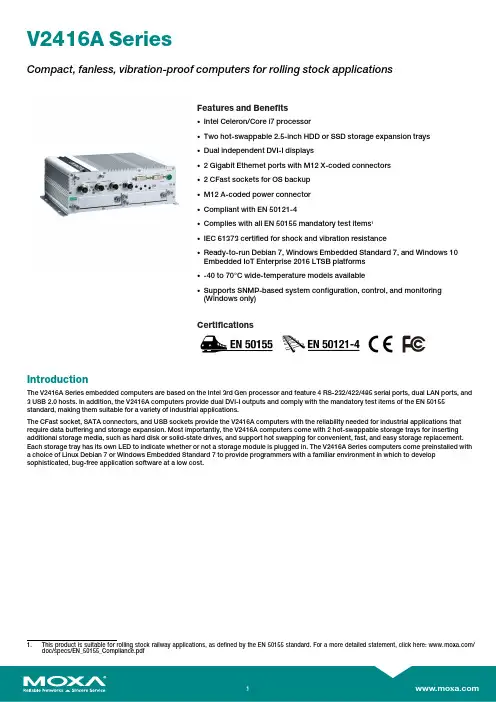
V2416A SeriesCompact,fanless,vibration-proof computers for rolling stock applicationsFeatures and Benefits•Intel Celeron/Core i7processor•Two hot-swappable2.5-inch HDD or SSD storage expansion trays•Dual independent DVI-I displays•2Gigabit Ethernet ports with M12X-coded connectors•2CFast sockets for OS backup•M12A-coded power connector•Compliant with EN50121-4•Complies with all EN50155mandatory test items1•IEC61373certified for shock and vibration resistance•Ready-to-run Debian7,Windows Embedded Standard7,and Windows10Embedded IoT Enterprise2016LTSB platforms•-40to70°C wide-temperature models available•Supports SNMP-based system configuration,control,and monitoring(Windows only)CertificationsIntroductionThe V2416A Series embedded computers are based on the Intel3rd Gen processor and feature4RS-232/422/485serial ports,dual LAN ports,and 3USB2.0hosts.In addition,the V2416A computers provide dual DVI-I outputs and comply with the mandatory test items of the EN50155 standard,making them suitable for a variety of industrial applications.The CFast socket,SATA connectors,and USB sockets provide the V2416A computers with the reliability needed for industrial applications that require data buffering and storage expansion.Most importantly,the V2416A computers come with2hot-swappable storage trays for inserting additional storage media,such as hard disk or solid-state drives,and support hot swapping for convenient,fast,and easy storage replacement. Each storage tray has its own LED to indicate whether or not a storage module is plugged in.The V2416A Series computers come preinstalled with a choice of Linux Debian7or Windows Embedded Standard7to provide programmers with a familiar environment in which to develop sophisticated,bug-free application software at a low cost.1.This product is suitable for rolling stock railway applications,as defined by the EN50155standard.For a more detailed statement,click here:/doc/specs/EN_50155_Compliance.pdfAppearanceFront View Rear ViewSpecificationsComputerCPU V2416A-C2Series:Intel®Celeron®Processor1047UE(2M cache,1.40GHz)V2416A-C7Series:Intel®Core™i7-3517UE Processor(4M cache,up to2.80GHz) System Chipset Mobile Intel®HM65Express ChipsetGraphics Controller Intel®HD Graphics4000(integrated)System Memory Pre-installed4GB DDR3System Memory Slot SODIMM DDR3/DDR3L slot x1Supported OS Linux Debian7Windows Embedded Standard7(WS7E)32-bitWindows Embedded Standard7(WS7E)64-bitStorage Slot CFast slot x2Computer InterfaceEthernet Ports Auto-sensing10/100/1000Mbps ports(M12X-coded)x2Serial Ports RS-232/422/485ports x4,software selectable(DB9male)USB2.0USB2.0hosts x1,M12D-coded connectorUSB2.0hosts x2,type-A connectorsAudio Input/Output Line in x1,Line out x1,M12D-codedDigital Input DIs x6Digital Output DOs x2Video Input DVI-I x2,29-pin DVI-D connectors(female)Digital InputsIsolation3k VDCConnector Screw-fastened Euroblock terminalDry Contact On:short to GNDOff:openI/O Mode DISensor Type Dry contactWet Contact(NPN or PNP)Wet Contact(DI to COM)On:10to30VDCOff:0to3VDCDigital OutputsConnector Screw-fastened Euroblock terminalCurrent Rating200mA per channelI/O Type SinkVoltage24to40VDCLED IndicatorsSystem Power x1Storage x1Hot-swappable2LAN2per port(10/100/1000Mbps)Serial2per port(Tx,Rx)Serial InterfaceBaudrate50bps to921.6kbpsFlow Control RTS/CTS,XON/XOFF,ADDC®(automatic data direction control)for RS-485,RTSToggle(RS-232only)Isolation N/AParity None,Even,Odd,Space,MarkData Bits5,6,7,8Stop Bits1,1.5,2Serial SignalsRS-232TxD,RxD,RTS,CTS,DTR,DSR,DCD,GNDRS-422Tx+,Tx-,Rx+,Rx-,GNDRS-485-2w Data+,Data-,GNDRS-485-4w Tx+,Tx-,Rx+,Rx-,GNDPower ParametersInput Voltage12to48VDCPower Connector M12A-coded male connectorPower Consumption(Max.) 3.3A@12VDC0.82A@48VDCPower Consumption40W(max.)Physical CharacteristicsHousing AluminumIP Rating IP30Dimensions(with ears)250x86x154mm(9.84x3.38x6.06in)Dimensions(without ears)275x92x154mm(10.83x3.62x6.06in)Weight4,000g(8.98lb)Installation DIN-rail mounting(optional),Wall mounting(standard) Protection-CT models:PCB conformal coating Environmental LimitsOperating Temperature Standard Models:-25to55°C(-13to131°F)Wide Temp.Models:-40to70°C(-40to158°F) Storage Temperature(package included)-40to85°C(-40to185°F)Ambient Relative Humidity5to95%(non-condensing)Standards and CertificationsEMC EN55032/24EMI CISPR32,FCC Part15B Class AEMS IEC61000-4-2ESD:Contact:6kV;Air:8kVIEC61000-4-3RS:80MHz to1GHz:20V/mIEC61000-4-4EFT:Power:2kV;Signal:2kVIEC61000-4-5Surge:Power:2kVIEC61000-4-6CS:10VIEC61000-4-8PFMFRailway EN50121-4,IEC60571Railway Fire Protection EN45545-2Safety EN60950-1,IEC60950-1Shock IEC60068-2-27,IEC61373,EN50155Vibration IEC60068-2-64,IEC61373,EN50155DeclarationGreen Product RoHS,CRoHS,WEEEMTBFTime332,173hrsStandards Telcordia(Bellcore),GBWarrantyWarranty Period3yearsDetails See /warrantyPackage ContentsDevice1x V2416A Series computerInstallation Kit8x screw,for storage installation2x storage key1x wall-mounting kit8x washer,for HDD/SSDDocumentation1x document and software CD1x quick installation guide1x warranty cardDimensionsOrdering InformationModel Name CPU Memory(Default)OS CFast(CTO)Backup CFast(CTO)Hot-SwappableSSD/HDD Tray(CTO)Operating Temp.ConformalCoatingV2416A-C2Celeron1047UE4GB or optional1(Optional)1(Optional)2(Optional)-25to55°C–V2416A-C2-T Celeron1047UE4GB or optional1(Optional)1(Optional)2(Optional)-40to70°C–V2416A-C2-CT-T Celeron1047UE4GB or optional1(Optional)1(Optional)2(Optional)-40to70°C✓V2416A-C7i7-3517UE4GB or optional1(Optional)1(Optional)2(Optional)-25to55°C–V2416A-C7-T i7-3517UE4GB or optional1(Optional)1(Optional)2(Optional)-40to70°C–V2416A-C7-CT-T i7-3517UE4GB or optional1(Optional)1(Optional)2(Optional)-40to70°C✓V2416A-C2-W7E Celeron1047UE4GB8GB1(Optional)2(Optional)-25to55°C–V2416A-C2-T-W7E Celeron1047UE4GB8GB1(Optional)2(Optional)-40to70°C–V2416A-C7-T-W7E Core i7-3517UE4GB8GB1(Optional)2(Optional)-40to70°C–Accessories(sold separately)AntennasANT-WDB-ANF-0407 2.4/5GHz,omni-directional antenna,4/7dBi,N-type(male)Battery KitsRTC Battery Kit Lithium battery with built-in connectorConnectorsM12A-5PMM-IP685-pin male circular threaded D-coded M12USB connector,IP68M12X-8PMM-IP678-pin male X-coded circular threaded gigabit Ethernet connector,IP67Power AdaptersPWR-24270-DT-S1Power adapter,input voltage90to264VAC,output voltage24V with2.5A DC loadPower CordsPWC-C7AU-2B-183Power cord with Australian(AU)plug,2.5A/250V,1.83mPWC-C7CN-2B-183Power cord with two-prong China(CN)plug,1.83mPWC-C7EU-2B-183Power cord with Continental Europe(EU)plug,2.5A/250V,1.83mPWC-C7UK-2B-183Power cord with United Kingdom(UK)plug,2.5A/250V,1.83mPWC-C7US-2B-183Power cord with United States(US)plug,10A/125V,1.83mDIN-Rail Mounting KitsDK-DC50131-01DIN-rail mounting kit,6screwsWall-Mounting KitsV2400Isolated Wall Mount Kit Wall-mounting kit with isolation protection,2wall-mounting brackets,4screws©Moxa Inc.All rights reserved.Updated Nov12,2018.This document and any portion thereof may not be reproduced or used in any manner whatsoever without the express written permission of Moxa Inc.Product specifications subject to change without notice.Visit our website for the most up-to-date product information.。

TD1600/VX1600便携式显示器使用手册型号:VS18044/VS18045P/N:TD1600/VX1600感谢您选择ViewSonic作为世界领先显示解决方案提供商,ViewSonic 一直专注在技术发展、创新和简单化方面超过世界的预期。
在ViewSonic,我们相信我们的产品能够对世界产生积极的影响,并且我们深信您选择的View-Sonic 产品会很好地为您服务。
再次感谢选择ViewSonic!目录1.注意事项与警告 (1)2.准备使用 (3)2-1. 包装物品 (4)2-2. 显示器外观 (5)2-3. 硬件安装 (6)2-4. 快速安装 (9)2-5. 电源开启 (11)3.调整屏幕图像 (12)3-1. 设置时序模式 (12)3-1. 使用控制面板 (13)4.OSD菜单介绍 (15)4-1. OSD菜单树 (15)4-2. OSD菜单说明 (21)4-3. 显示器设置管理 (25)5.技术规格 (26)6.故障诊断 (28)7.清洁和维护 (29)如何清洁显示器 (29)8.电磁相容信息 (31)8-1. FCC 符合性声明 (31)8-2. 加拿大工业部声明 (31)8-3. 针对欧盟国家的CE 符合性 (32)8-4. 电子电气产品有害物质限制使用标识要求 (33)8-5. 产品达到使用寿命后废弃产品 (34)9.版权信息 (35)10.服务信息 (36)客户支持 (36)有限保修 (38)1.注意事项与警告1.在使用设备之前,仔细阅读这些指导说明。
2.妥善保管这些指导说明。
3.注意所有警告并遵照所有指示。
4.使用显示器时,请保持离屏幕约40-50 公分的距离。
5.在移动时务必小心搬动显示器。
6.切勿拆下后盖。
显示器内有高压零件。
如果您触碰这些零件,可能会受到严重伤害。
7.请勿在靠近水的地方使用本设备。
警告: 为减低火灾或电击的危险,请勿将此产品暴露在雨或潮湿的环境中。
8.避免将显示器直接暴露在阳光或其它热源中。


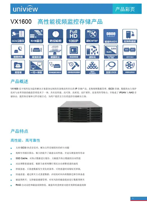
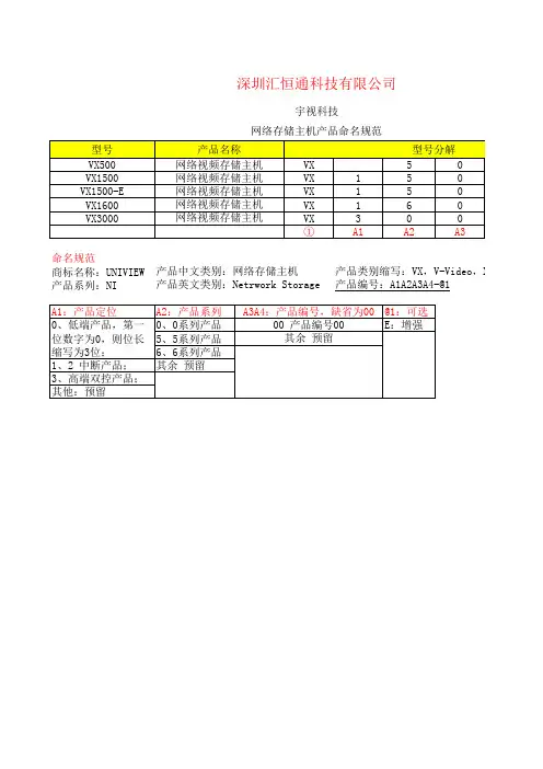
1产品彩页VX1600高性能视频监控存储产品产品概述VX1600是宇视科技为监控解决方案量身定制的具备极高性价比的IP存储产品,是集视频数据管理、iSCSI存储、数据的永久保护技术与业界顶级的磁盘管理技术于一体,具有高性能、高可靠、高密度、高扩展性、高易用性等特点,并集成了IPSAN与NAS存储协议,提供块存储和文件存储方式,为用户提供全方位的监控存储解决方案。
产品特点高性能、高可靠性支持iSCSI块直存技术,解决文件存储固有的碎片问题视频专用缓存算法,极大的提升了磁盘访问性能,并延长硬盘使用寿命SSD Cache,对热点数据进行缓存,大幅提升热点数据的访问性能动态调整重建速度,根据当前系统繁忙情况自动调整重建的速度秒级重建,只重建数据发生变化的条带,可将重建时间缩短至秒级,快速重建,通过拷贝方式重建数据,在较短时间内将数据迁移至热备盘磁盘预拷贝,支持磁盘健康管理,对有风险的磁盘提前进行数据预拷贝RAID自动巡检和磁盘故障修复、磁盘坏块重映射功能有效降低磁盘故障V X1600产品彩页2 硬盘容错处理,在阵列多个磁盘错误的情况下,仍然保证业务可持续提供阵列N+1备份,阵列失效,数据自动切换,保证业务连续性阵列多块磁盘失效,视频数据可读,保证数据的可用性RAID超级块的多备份设计,提高阵列的可靠性数据保险箱功能,在系统异常断电时可以继续供电以保证将缓存数据写入数据保险箱,保证数据的完整性支持链路聚合和动态故障切换,在保证数据读写带宽的同时保障数据通路的可用和畅通基于策略定义的文件级备份,对关键数据的文件进行本地或远程备份配合IMOS平台,实现前端缓存补录保护,N+M保护高品质的硬件设计独具创新的4U 24盘位,589mm深度,适用于最广泛的机柜安装,且节省空间基于Intel 64位多核处理器、支持ECC DDR3内存和64位专用存储操作系统,保证系统在7X24小时海量视频数据连续存取时的稳定性和可靠性,系统可用性达到99.999%电源、电池、风扇模块化冗余设计,支持热插拔及在线更换系统watchdog功能,在系统故障时将强制系统进入安全模式,高速缓存中的数据将被存入数据保险箱,数据保险箱存储介质可以和阵列硬盘一起漫游到新系统,系统恢复安全、简便独有双BIOS设计,保证系统可靠启动和更新BIOS硬件过载保护机制,当温度异常升高达到硬件保护门限,则系统会自动关机以保护磁盘数据采用磁盘顺序加电方式,降低启动冲击电流,确保系统电源安全独特磁盘防尘防震设计,有效阻挡灰尘,降低硬盘共振传递以及外界冲击三维线性扩展逻辑资源的在线无缝扩容,可实现本设备的跨阵列纵向扩容和跨设备的横向扩容标配2个前端千兆业务接口,可扩展至10个千兆业务接口,或扩展4个万兆业务接口,后端扩展模块支持2个4x12Gbps SAS GEN3 宽端口(SAS3.0)。
DAM1600E继电器控制卡说明书V1.1北京聚英翱翔电子有限公司2016年07月目录一、产品特点 (1)二、产品功能 (1)三、产品选型 (1)四、主要参数 (1)五、接口说明 (2)六、通讯接线说明 (2)1、RS232接线方式 (2)2、RS485级联接线方式 (3)七、输出接线说明 (3)1、继电器接线说明 (3)八、测试软件说明 (3)1、软件下载 (3)2、软件界面 (4)3、通讯测试 (4)九、参数配置 (5)1、设备地址 (5)2、波特率的读取与设置 (7)3、闪开闪断功能及设置 (7)十、开发资料说明 (8)1、通讯协议说明 (8)2、Modbus寄存器说明 (8)3、指令生成说明 (10)4、指令列表 (11)5、指令详解 (12)十一、常见问题与解决方法 (14)十二、技术支持联系方式 (14)一、产品特点●DC7-30V;●继电器输出触点隔离;●采用欧姆龙G2R-A-E继电器可更换;●通讯接口支持RS485、RS232;●通信波特率:2400,4800,9600,19200,38400(可以通过软件修改,默认9600);●通信协议:支持标准modbus RTU协议;●可以设置0-255个设备地址,可以通过软件设置;●具有闪开、闪断功能,可以在指令里边带参数、操作继电器开一段时间自动关闭;●具有频闪功能,可以控制器继电器周期性开关;●加入高频滤波器,提高产品的抗扰度,阻挡电网不干净电源对设备的影响。
二、产品功能●十六路继电器控制●支持电脑软件手动控制●支持顺序启动模式●支持流水循环模式●支持跑马循环模式三、产品选型型号modbus RS232RS485USB WiFi继电器DAM1600E-RS232+485●●●16四、主要参数参数说明触点容量16A/30VDC16A/250VAC耐久性10万次数据接口RS485、RS232额定电压DC7-30V电源指示1路红色LED指示(不通信时常亮,通信时闪烁)通讯指示与电源指示灯共用输出指示16路红色LED指示温度范围工业级,-40℃~85℃尺寸180*94*41mm重量330g默认通讯格式9600,n,8,1波特率2400,4800,9600,19200,38400软件支持配套配置软件、控制软件;支持各家组态软件;支持Labviewd等五、接口说明六、通讯接线说明1、RS232接线方式RS232接线为标准DB9母头接口,为直连线。
S CU -1600 C on tr o l un itS T P -A 2203/2503/2803/3003/3503●S T P -F 2203●S T P -XA2703/3203/4503●S T P -X H 2603/3203●Ad v an c ed p r e -m a i ntenan c e fun c t i on ●P r e cis e m a i ntenan c e t imi ng ●Tw o s tage w a r n i ng m e ss age s ●R oto r im ba l an c e m on i to ri ng●Ba ck-up bea ri ng da m age m on i to ri ng●F eatu r e s & Benef i t sApp lic at i onsP u m p to c ont r o ll e r c ab l eM agnet ic bea ri ng c ont r o l sys te m Di g i ta l c ont r o l Input v o l tage200 – 240 ±10 V a.c .Po w e r c on s u m pt i on (wi thout T e m pe r atu r e M anage m ent S ys te m , TM S )M a x 1600 VA Po w e r c on s u m pt i on (wi th TM S )M a x 2100 VA Input f r equen cy 50/60 ±2 Hz Lea k c u rr ent3.5 m A M a i n b r ea k e r r ated c u rr ent 15 A M oto r d riv e sys te m3-pha s e d.c .A ll o w ab l e a m b i ent te m pe r atu r e 0 to 40 °C (32 to 104 °F)W e i ght12 k g TM S c ont r o l un i tBu il t -i n Se ri a l c o mm un ic at i on fun c t i on (R S232/R S485)Standa r dOpe r at i on swi t c h Sta r t, Stop, R e s et, Se l e c t, U p,D o w n, Ente r , M anua l /R e m ote Pane l d is p l a yL CDDim en si on s T e c hn ic a l D ataP r odu c t D escri pt i onOr d er No .S CU-1600 T u r bo Pu m p C ont r o l U n i tY T 76Z 0Z 00A ccess o ries & S p aresOr d er No .Po w e r c ab l e, 5m Y T 76Y0A01Po w e r c ab l e, 10m Y T 76Y0A02Po w e r c ab l e, 15m Y T 76Y0A03Po w e r c ab l e, 20mY T 76Y0A04S T P s t r a i ght c onne c t i on c ab l e, 5m B75030010S T P s t r a i ght c onne c t i on c ab l e, 10m B75030040S T P s t r a i ght c onne c t i on c ab l e, 15m B75030220S T P s t r a i ghtc onne c t i on c ab l e, 20mB75030230O r de ri ng Info rm at i on2Pa g e 114T he fu lly d i g i ta l S CU-1600 tu r bo pu m p c ont r o l un i t is c o m pat i b l e wi th S T P tu r bo pu m p sr ang i ng f r o m 2000 ls -1 to 4500 ls -1. It p r o vi de s r e li ab ili t y , enhan c ed c o mm un ic at i on and pu m p c o m pat i b ili t y wi th r edu c ed ba ck-up un i t requ ire m ent s and mi n imiz ed o v e r a ll c o s t of o w ne rs h i p.。
H3C Neocean VX1500系列产品介绍1. 产品概述Neocean VX1500是H3C为监控解决方案量身定制的具备极高性价比的IP存储产品,稳定可靠,性能优异,简单易用,管理方便,并可动态扩展,轻松满足监控应用方案中的存储需求。
2. 产品特点专业的监控存储产品,稳定可靠●完全基于64位硬件体系和64位专用Linux存储操作系统,保证系统在7×24小时海量视频数据连续存取时的稳定性和可靠性。
●拥有2个前端GE接口,支持链路聚合和动态故障切换,在保证数据读写带宽的同时保障数据通路的可用和畅通。
●支持磁盘安全插拔特性。
在进行磁盘热插拔之前,通过在GUI界面操作来主动使磁盘停转,让磁头回到启停区,能将运行过程拔盘导致盘面被划伤的风险降到最低。
●支持磁盘漫游,即存储系统内部磁盘可以任意的更换位置,而磁盘内部的阵列配置信息和数据完全不会改变或丢失,可避免由于磁盘被错误插拔而导致的数据丢失。
●支持RAID 0、1、5、6、10等多种RAID级别,热备方式上可以选择专用热备盘、全局热备盘或空闲磁盘热备。
在创建RAID时,可以根据不同的应用模型来灵活设置RAID条带的大小,确保各种不同的应用都能够获得最佳性能。
另外,针对冗余RAID重建过程对业务性能的影响,VX1500能提供RAID重建速度动态调整特性,系统会根据当前系统繁忙情况自动调整重建的速度,一方面降低RAID重建对于业务性能的影响,另一方面可以有效提高系统资源利用率。
●VX1500可选配冗余的、负载均衡的热插拔电源,支持电源自动故障切换和在线故障电源更换,还支持多种型号的外接UPS,避免电源故障带来的系统异常。
多个冗余风扇可对所有的磁盘和控制单元进行散热,可保证整个系统长时间的正常稳定运行。
●缓存掉电保护功能可在供电故障时为VX1500的缓存数据提供长达72小时的保护时间,有效防止数据丢失。
VX1500在启动时采用磁盘顺序加电方式,保证不会由于所有磁盘同时加电引起电源或系统故障。
1 初始化配置1.1 设置端口IP和MTU(1) 在系统串口用interface命令为管理口配置IP,输入的命令如下所示:<Storware>system interface set ip port=eth0说明:●port指定要设置的端口,address指定设置端口的IP地址,netmask指定设置端口的网络掩码,mtu如不设置,则默认为1500。
●配置管理FE口后,就可以通过GUI界面来对VX1600进行管理操作。
当然,前提是管理PC能够ping通 VX1600管理FE口,允许GUI配置控制台通过业务网口登录。
(2) 用新配置的管理口IP登录存储界面,右键单击存储服务器名称,通过【系统维护/网络配置】进行其他业务口IP和服务器名称的更改,如图9-2所示:注意:●进行“网络配置”设置后,会出现服务器连接中断的提示,点击【确定】后,重新连接服务器。
●业务口MTU默认值为1500,不建议修改。
图9-2 在界面上进行服务器的IP和名称设置(3) 选择【系统维护/网络配置】,选择需要进行设置的端口后,单击【设置】按钮,如图9-3所示:图9-3 选择需要设置的端口(4) 在新弹出的窗口中进行端口IP地址和掩码的输入,输入完成并确认无误后,单击【确定】按钮,如图9-4所示:(5) 重复步骤(2)~(4)设置所有的端口IP,设置完成后可通过【系统维护/网络配置】选项查。
图9-4 进行服务器的IP和掩码设置1.2 设置服务器名称操作步骤如下:(1) 右键单击存储服务器名,选择图9-2中的【系统维护/服务器名称设置】菜单,在弹出的对话框中输入新的服务器名,如图9-5所示;(2) 如果没有特殊要求,请按照“局点名拼音缩写-设备标号”的格式进行命名。
假如局点是中央电大,只有一套设备(设备标号为1),则存储服务器的名称为:zydd-1。
注意:●不允许将服务器名称设置成中文。
●在界面修改服务器名称之后,系统会自动重启。
Setting up Embedded Controllers and Mainframe Extenders as Non-Slot 0 Devices,Non-Resource ManagersThis document describes how to configure various National Instruments VXI/VME controllers for non-slot 0, non-resource manager operation.Table of ContentsVXIpc-800/700 Series(Page 2)VXI/VMEpc 600 Series(Page 4)VXI-MXI-2(Page 5)VME-MXI-2(Page 6)VXI-1394 and VXI-1394/G (Page 6)VXIpc-486 Model 500 Series(Page 6)VXI-MXI(Page 8)VME-MXI(Page 13)VXIcpu-030(Page 15)VXIpc-800/700 Series (includes Vxipc-870 series)HardwareNo changes are necessary. By default the VXIpc-800/700 Series uses automatic Slot 0detection. Install the board in a slot other than Slot 0.Optional Change:It is possible to manually configure the VXIpc-800/700 Series for Slot 0 or Non-Slot 0operation by changing jumper settings.On the VXIpc-870 series, use jumper J12 to make this change as shown below.On the VXIpc-800 Series, use jumper W13 to make this change.W13a. M a nual Non-Slot 0onfiguration W13b. utomatic Slot 0etection efault W13c. M a nual Slot 0onfigurationOn the VXIpc-700 Series, you can make this change with jumper W1.W1a. M a nual Non-Slot 0onfiguration W1b. utomatic Slot 0etection efault W1c. M a nual Slot 0onfigurationSoftwareNote that installing a device in Slot 0 does not necessarily imply that it is also the Resource Manager device, and vice versa. A device that is not in Slot 0 can stillperform the Resource Manager configuration, and conversely, a Slot 0 device doesnot necessarily need to be Logical Address 0 (Resource Manager). Changing thelogical address can be considered optional.T&M Explorer:1.Open the Hardware Configuration editor for the VXIpc by right clicking on its entryin Test and Measurement Explorer. Under the Device tab, change the LogicalAddress parameter from 0 to a non-zero value.2.Under the VXI tab, change the VXI Bus Timeout parameter to Disable.3.Save your changes in T&M Explorer and rerun Resman.Note: You must be logged on with administrative privileges if you are using Windows NT.Note:If your board is set up as a message-based device, it must wait for the Word Serial command Begin Normal Operation from the actual Resource Manager device(device at Logical Address 0).Note:You do not need to run the Resman on the VXIpc if it is set up as a register based device.Note:You can specify your device type (message or register based) by specifying the Device Class under the Device tab.VXIedit/VXItedit:1.Open the VXIpc-Configuration Editor, and in the Logical Address ConfigurationEditor, change the Logical Address parameter from 0 to a non-zero value.2.Switch to the Bus Configuration Editor and change the VXI Bus Timeout parameterto DISABLE.3.Save your changes in VXIedit/VXItedit and rerun VXIinit and Resman.Note:If your board is set up as a message-based device, it must wait for the Word Serial command Begin Normal Operation from the actual Resource Manager device (atLogical Address 0).Note:If your board is set up as a register-based device, you don’t have to run Resman on it.Note:To set whether your board is message based or register based, go into VXIedit/VXItedit, open the VXIpc Configuration Editor, and in the LogicalAddress Configuration Editor, edit the Device Type field.(MBD = Message Based Device, RBD = Register Based Device)VXI/VMEpc-600 SeriesHardwareNo changes are necessary. By default the VXI/VMEpc-600 Series uses automatic Slot 0 detection. Install the board in a slot other than Slot 0.Optional Change:It is possible to manually configure the VXI/VMEpc-600 Series for Slot 0 or Non-Slot 0 operation with jumper W11 as shown below.SoftwareNote that installing a device in Slot 0 does not necessarily imply that it is also the Resource Manager device, and vice versa. A device that is not in Slot 0 can stillperform the Resource Manager configuration, and conversely, a Slot 0 device does not necessarily need to be Logical Address 0 (Resource Manager). Changing thelogical address can be considered optional.T&M Explorer:4.Open the Hardware Configuration editor for the VXIpc by right clicking on its entryin Test and Measurement Explorer. Under the Device tab, change the LogicalAddress parameter from 0 to a non-zero value.5.Under the VXI tab, change the VXI Bus Timeout parameter to Disable.6.Save your changes in T&M Explorer and rerun Resman.Note: You must be logged on with administrative privileges if you are using Windows NT.Note:If your board is set up as a message-based device, it must wait for the Word Serial command Begin Normal Operation from the actual Resource Manager device(device at Logical Address 0).Note:You do not need to run the Resman on the VXI/VMEpc if it is set up as a registerbased device.Note:You can specify your device type (message or register based) by specifying theDevice Class under the Device tab.VXI-MXI-2 (Non-Slot 0)HardwareNo changes are necessary. By default the VXI-MXI-2 uses automatic Slot 0 detection.Install the board in a slot other than Slot 0.Optional Change:It is possible to manually configure the VXI-MXI-2 for Slot 0 or Non-Slot 0 operation by changing jumper W2 settings, as shown below.a. A u tomatic Slot 0 Detection (Default)b. Manual Slot 0 C o nfigurationc. Manual Nonslot 0 C o nfigurationSlot 0AutoNonslot 0Slot 0AutoNonslot 0Slot 0Auto Nonslot 0W2SoftwareNo changes are necessary.VME-MXI-2 (Non-Slot 1)HardwareNo changes are necessary. By default the VME-MXI-2 uses automatic VME Slot 1 detection. Install the board in a slot other than Slot 1.Optional Change:It is possible to manually configure the VME-MXI-2 for Slot 1 or Non-Slot 1 using VXIedit or Test and Measurement Explorer. This might be necessary if your VME chassis does not comply with the VME64 specification for automatic detection of the Slot 1 position. You must put the VME-MXI-2 in a VME 64 compliant chassis in order to set this option.VXI-1394 and VXI-1394/GNI VXI 2.0 does not support using VXI-1394 interfaces in a multi mainframe configuration and so there is no reason to put a VXI-1394 in any slot other than slot 0. Future revisions of NI-VXI may support this functionalityVXIpc-486 Model 500 SeriesHardware1.The W26 jumper controls the MODID signal termination setting. Move this jumper tothe leftmost two pins as shown below.W26a. Slot 0 (Factory Configuration)b. Non-Slot 02.The W25 jumper (underneath the hard drive) controls the System Controller setting.Move this jumper to the upper two pins as shown below.a. Slot 0(Factory Configuration)b. Non-Slot 03.Move the jumpers at W35 and W36 to W32 and W33in the block of pins. Thesejumpers control the CLK10 setting for Slot 0/Non-Slot 0.a. Slot 0 OnboardCLK10 Source(Factory Configuration)b. Non-Slot 0W33W36W35W324.Install the board in a slot other than Slot 0.Software1.In VXIedit/VXItedit, open the Configuration Editor, and in the Logical AddressConfiguration Editor, change the Logical Address parameter from 0 to a non-zero value. Notice that installing a device in Slot 0 does not necessarily imply that it is also the Resource Manager device, and vice versa. A device that is not in Slot 0 can still perform the Resource Manager configuration, and conversely, a Slot 0 device does not necessarily need to be Logical Address 0 (Resource Manager). Changing thelogical address can be considered optional.2.Switch to the Bus Configuration Editor and change the Local Bus Timeout parameterto DISABLE.3.In the Bus Configuration Editor, change the VXI Bus Timeout parameter toDISABLE.4.Save your changes in VXIedit/VXItedit and rerun VXIinit and Resman.Note:If your board is set up as a message-based device, it must wait for the Word Serial command Begin Normal Operation from the actual Resource Manager device (atLogical Address 0).Note:If your board is set up as a register-based device, you don’t have to run Resman on it.Note:To set whether your board is message based or register based, go into VXIedit/VXItedit, open the Configuration Editor, and in the Logical AddressConfiguration Editor, edit the Device Type field.(MBD = Message-Based Device, RBD = Register-Based Device)VXI-MXI (Non-Slot 0)Hardware1.Move switch S1 to the upper position (Non-Slot 0 setting) as shown below.2.Move switch S8 to the right position (Non-Slot 0 setting), as shown below. You mustalways ensure that the positions of S1 and S8 match. For Non-Slot 0, the dots on both switches need to be covered.3.Move the CLK10 Source jumpers at W9 and W10 from the first row (figure a, below)to the third row (figure c) to the Receive CLK10, Non-Slot 0 setting.a. Onboard 10MHz VXI-MXI Installed in Slot 0 (Default Setting)CLK10 SourceDrive CLK10 from onboard 10MHz, Slot 0Drive CLK10 from SMB CLK10, Slot 0Receive CLK10, Non-Slot 0b. External Clock VXI-MXI Installed in Slot 0CLK10 SourceW10W9Drive CLK10 from onboard 10MHz, Slot 0Drive CLK10 from SMB CLK10, Slot 0Receive CLK10, Non-Slot 0c. Do Not Source CLK10; VXI-MXI Not Installed in Slot 0CLK10 SourceDrive CLK10 from onboard 10MHz, Slot 0Drive CLK10 from SMB CLK10, Slot 0Receive CLK10, Non-Slot 0d. Source CLK10 from INTX VXI-MXI Installed in Slot 0CLK10 SourceW10W9Drive CLK10 from onboard 10MHz, Slot 0Drive CLK10 from SMB CLK10, Slot 0Receive CLK10, Non-Slot 04.Move one of the three VMEbus Timeout Chain Position jumpers in the block of pinsat W7 as shown below. This jumper controls the VMEbus Timeout Chain Position setting.W7VME BTOa. One VXI-MXI, in Slot 0(Default Setting)W7VME BTOb. One VXI-MXI, Non-Slot 05.Install the board in a slot other than Slot 0.Optional Changes:1.If you need to change the logical address of the VXI-MXI from its default value of 1,set the DIP switches to the new logical address. The DIP switches represent bits 7 to 0 in forming the VXI-MXI’s logical address. DIP switch 1 represents bit 7 (decimal value of 128), DIP switch 2 represents bit 6 (decimal value of 64), and so on. Push down on the OFF side to set the bit.Example:If DIP switches 1 and 2 are pushed down on the OFF side, theVXI-MXI is set to logical address hex C0, or decimal 192(128 + 64 = 192).b. Switch Set to Logical Address hex C0LOGICAL ADDRESSa. Switch Set to Default Setting Logical AddressLOGICAL ADDRESS2.If the VXI-MXI needs to be the MXIbus System Controller, move switch S4 to cover the dot as shown below.S4MXIbus System Controller EnabledDisabledb. MXIbus System ControllerS4MXIbus System Controller EnabledDisableda. Not MXIbus System Controller(Default Setting)Note:If the VXI-MXI is the MXIbus System Controller, it sets the MXIbus SystemController Timeout value. You can change the timeout by moving the jumper at W8 from the default value of 100 µs, as shown below.W8100 µ/ms 200 µ/ms 400 µ/ms DISABLEMXI Controller BTO Level c. 400 µs/ms MXIbusSystem Controller Timeout W8100 µ/ms 200 µ/ms 400 µ/ms DISABLEMXI Controller BTO Level a. 100 µs/ms MXIbus System ControllerTimeout (Default Setting)W8100 µ/ms 200 µ/ms 400 µ/ms DISABLEMXI Controller BTO Leveld. Disable MXIbus System Controller TimeoutW8100 µ/ms 200 µ/ms 400 µ/ms DISABLEMXI Controller BTO Levelb. 200 µs/ms MXIbusSystem Controller Timeout3.If the VXI-MXI needs to stop performing the VMEbus Timeout function, move the jumper at W6 to the bottom (fourth) row of pins (labeled DISABLE ).W6100 µs 200 µs 400 µs DISABLEVME BTO Level c. 400 µs BTOW6100 µs 200 µs 400 µs DISABLEVME BTO Levela. 100 µs BTO (Default Setting)W6100 µs 200 µs 400 µs DISABLEVME BTO Level d. Disable BTOW6100 µs 200 µs 400 µs DISABLEVME BTO Level b. 200 µs BTONote:You should let the VXI-MXI perform the VMEbus Timeout function, if at allpossible, because this will generally allow MXIbus transfers more time to complete. If the VXI-MXI is performing the VMEbus Timeout function, make sure no other VXI devices are trying to perform this function. For example, if you have a National Instruments embedded controller in the mainframe, use its VXI Resource Editor, VXIedit/VXItedit, to set its Local Bus Timeout and VXIbus Timeout parameters to DISABLE .VME-MXI-1 (Non-Slot 1)Hardware1.Move switch S5 to cover the dot. This position configures the VME-MXI to not bethe VMEbus System Controller.a. VMEbus System Controller (Default Setting)b. Not VMEbus System Controller2.Install the board in a slot other than Slot 1.Optional Changes:1.If you need to change the logical address of the VME-MXI from its default value of 1,set the DIP switches at U94 to a new logical address. The DIP switches represent bits 7 to 0 in forming the VME-MXI ’s logical address. DIP switch 1 represents bit 7(decimal value of 128), DIP switch 2 represents bit 6 (decimal value of 64), and so on.Push down on the OFF side to set the bit.Example:If DIP switches 2, 4, and 6 are pushed down on the OFF side, theVME-MXI is set to logical address hex 54, or decimal 84(64 + 16 + 4 = 84).b. Switch Set to Logical Address hex 54a. Switch Set to Default Setting(Logical Address 1)2.If the VME-MXI needs to be the MXIbus System Controller, move switch S4 to cover the dot. This position configures the VME-MXI to be the MXIbus SystemController.S4S4a. Not MXIbus System Controller (Default Setting)b. MXIbus System ControllerNote:If the VME-MXI is the MXIbus System Controller, it sets the MXIbus SystemController Timeout value. You can change the timeout by moving the jumper at W7 from the default value of 100 µs.b. 200 µsec/20 msec MXIbus System Controller Timeouta. 100 µsec/10 msec MXIbus System Controller Timeout(Default Setting)d. Disable MXIbus System Controller Timeout GenerationW7W7c. 400 µsec/40 msec MXIbus System Controller Timeout3.If the VME-MXI needs to stop performing the VMEbus Timeout function (possibly because another VME device cannot relinquish the VMEbus Timeout function), move the jumper at W8 to the set of pins farthest from the W8inscription.b. 200µsec BTOa. 100 µsec BTO (Default Setting)d. Disable BTOc. 400 µsec BTO Note:You should let the VME-MXI perform the VMEbus Timeout function, if at allpossible, because this generally allows MXIbus transfers more time to complete. If the VME-MXI is performing the VMEbus Timeout function,make sure no other VME devices are trying to perform this function.VXIcpu-030Hardware1.Move switch S10 away from the arrow to cover the dot. This setting configures theVXIcpu-030 MODID signal termination for Non-Slot 0.S10SLOT 0S10a. MODID Signal Terminationfor Slot 0 Operation (Factory Configuration)b. MODID Signal Termination for Non-Slot 0 OperationSLOT 02.Move switch S8 away from the arrow to cover the dot. This switch controls whether the VXIcpu-030 acts as the System Controller.S8SLOT 0S8a. System Controller Functions Enabled for Slot 0 Operation (Factory Configuration)b. System Controller Functions Disabled for Non-Slot 0 OperationSLOT 03.Move the jumper at W1 (located on the back side of the VXIcpu-030) to the column of pins farthest from the SLOT 0 inscription). This jumper controls the backplane CLK10 setting.b. Non-Slot 0SLOT 0SLOT 0a. Slot 0, CLK10 Source (Factory Configuration)4.Move switch S83 from its default position to expose the dot on the switch. Thisswitch controls the CLK10 Source Selection setting.S83a. Onboard 10-MHz sources CLK10(Factory Configuration)b. Front Panel CLK I/OSources CLK105.Install the board in a slot other than Slot 0.Software1.In VXItedit, open the Configuration Editor, and in the Logical Address ConfigurationEditor, change the Logical Address parameter from 0 to a non-zero value. Notice that installing a device in Slot 0 does not necessarily imply that it is also the Resource Manager device, and vice versa. A device that is not installed in Slot 0 can stillperform the Resource Manager configuration and, conversely, a Slot 0 device does not necessarily need to be Logical Address 0 (Resource Manager). Changing thelogical address can be considered optional.2.Switch to the Bus Configuration Editor and change the VXI Bus Timeout parameterto 0 (disabled).3.Save your changes in VXItedit and rerun VXIinit and Resman.Note:If your board is set up as a message-based device, it must wait for the Word Serial command Begin Normal Operation from the actual Resource Manager device (atLogical Address 0).Note:If your board is set up as a register-based device, you don’t have to run Resman on it.Note:To set whether your board is message based or register based, go to the Logical Address Configuration Editor, and edit the Device Type field.(2 = message-based device, 3 = register-based device).。
VX1600单用户模式配置保存与恢复1 说明由于系统异常,导致无法登录存储系统来获取配置信息;可通过进入单用户模式,导出相关的数据库文件,转存为配置文件后,通过GUI配置恢复到新的存储服务器上。
选择导出的数据库文件只有initiator和target相关的,其他配置信息如果需要,请手动配置。
2 单用户模式下保存配置信息2.1 进入单用户模式打开存储设备的超级终端,(1)启动存储设备(2)在串口观察设备的重启过程,当出现“System Normal Start”时,按e键,如下图所示(3)进入grub界面,通过上下键选择进入kernel /vmlinuz-2.6.32……,如下图所示(4)继续按e键,进入编辑界面,在末尾加上“single”,如下图所示:(5)按Enter键,回到步骤3的界面,按b键,boot加载完成,如下图所示:2.2 给存储配置一个IP地址用于传输数据库文件如下配置eth0 192.168.11.84,确保跟ftp服务器192.168.11.83网络正常。
2.3 获取数据库文件,备份在/tmp目录下在单用户模式下执行如下命令获取数据库的txt文件:(1). 配置环境变量source /etc/profile(2). 启动数据库cfgmgt_start(3). 备份数据库到/tmp目录mysqldump -umysql -pmysql--socket=/usr/local/hstor/sms_install/etc/storware_db_file/stor_db_loc.sock -T/tmp store_configure如下图:2.4 配置FTP服务器用户名密码与共享文件夹保存FTPserver程序到个人电脑上,双击直接运行按照下图,添加FTP用户,配置密码、共享文件夹路径、访问权限等,并点击Apply按钮;最后点击绿色箭头按钮,开启FTP服务。
2.5 /tmp目录下的对应文件传输到FTP服务器上在/tmp目录下把如下文件取出到windows上(FTP服务器)在串口单用户模式下,输入ftp 192.168.11.83(FTP服务器地址),再输入2.4中配置的用户名和密码,如下通过mput命令将tb_iscsi_common_para.sql、tb_iscsi_common_para.txt两个文件传输到服务器上其他文件同样通过mput进行传输,如果无法传输,可能需要修改passive;2.6 将数据库文件保存为GUI能恢复的配置文件(1) 在一个新的存储(最好同版本)环境上执行配置保存;把保存的文件解压后,到如下目录下替换单用户模式下取出的文件:XXX目录\解压后的文件夹目录\SC\tmp\sw_config\mysql:(2)重新把文件打包成tar.gz格式(linux下打包最方便):把上面替换后的sw_config文件夹放在linux的/tmp目录下,执行打包命令:tar -czPf SC.tar.gz /tmp/sw_config/(3)重新再打包成zip格式:把上面的SC.tar.gz取出到windows上,用WINRAR软件打包成zip格式:(注意打开看一下,该zip文件双击打开第一级目录是如下:)3 新的存储控制器上恢复配置1、在存储控制器上选择配置恢复2、选择2.6中打包好的配置文件,执行配置恢复3、配置恢复成功恢复的target如果有已绑定IP地址,则该处恢复后target的IP地址也是原来的IP地址,所以需要新的存储环境配置IP和原来环境相同。
前言日照莱特智能科技有限公司是一家集研发、生产、销售、服务为一体的智能化安防科技企业,公司一直洞悉国内外智能科技行业发展最新动态,具有极强的凝聚力、严谨的工作作风和开阔的市场思路。
公司自成立以来,始终本着“诚信、务实、合作、进取”的企业理念,着眼于市场需求,高瞻远瞩,产品自我配套,自成体系。
主要经营:IC卡智能技术、智能停车场、智能通道闸、智能门禁、智能考勤、智能收费机、智能楼宇对讲、智能“一卡通”应用系统;遥控车库门、电动伸缩门、楼宇对讲门、感应自动门、旋转门、电动挡车道闸等智能机电一体化产品;视频监控、周界防范、智能巡更、防盗报警等智能安防系统;楼宇水电控制等智能化系统;岗亭、交通标志、减速带等交通配套设施,为各界的客户带来全新高科技感受。
企业的成功来源于高品质的产品与客户的信赖,公司寻求多层次、全方位的合作模式,共同推广江舜智能科技的应用,使现代建筑能及时享受到智能化和信息化带来的全新品质体验,让未来生活与工作变的更为舒适、安全、高效、节能。
莱特智能科技将树立积极务实、高效灵活、健康真诚的全新企业形象,愿与社会各界朋友携手共进,共同创造企业和社会的美好明天。
一、需求分析甲方的目标是可以随时远程实时浏览下述资产管理公司的资产管理目标相关视频监控资料,并能够回放不低于15天的录像资料。
甲方提出的原则是经济性、实用性、前瞻性及可扩展性。
二、解决方案整体架构随着数字技术和以IP技术为核心的网络技术的发展,监控系统由原先封闭的模拟系统逐渐向开放和标准的数字化、IP化系统发展。
大安防如同早期的监控,从专网向基于IP网络的安防系统发展,无论是安防联动还是安防集成,都离不开IP技术做支撑。
这里的IP已经扩展为基于IP网络的传输、通信、存储以及管理为核心的IT技术。
根据甲方的目标和要求,我公司采用浙江宇视科技的iVS(IP Video Surveillance)IP 智能监控解决方案。
宇视科技基于自身在网络技术、多媒体技术及存储技术等领域的长期技术积累,基于各行业拓展的应用经验,推出了iVS(IP Video Surveillance)IP智能监控解决方案,融合摄像机、编码器、混合式DVR、NVR、网络存储设备、管理平台与业务软件以及方案配套的承载网络,成为监控解决方案的端到端服务提供商。