氧传感器使用说明书(详细版)
- 格式:doc
- 大小:1.66 MB
- 文档页数:16
PE CS/CCS系列氧探头使用说明书使用前务必仔细越多!1.准备:1.1 要确保氧探头顶部锆头部分运输安全,因此有一个塑胶部件用来代替原有的锆件,通过旋开外管,可以拿下塑料元件已安装原来的锆件。
锆件将放入一个小的塑料容器内运输,他将被装进测量单元的终端连接盒。
如果氧探头交付,准备安装,你会发现一个随附的包装,即以上说明的这一点。
注意:陶瓷外管和锆件上的安装孔是不对称的,可以通过轻微的旋转调整,使它们安装到一起。
在除去塑胶部分安装好锆件后,外管必须逆着弹簧压力旋回。
注意:1.1是探头出口包装的首选的方法。
CCS 2000型准备交货安装时锆件已不能移动。
1.2 氧探头使用必须提供参比气,氧探头有连接参比气的接口。
参比气可以从ESS-ELECTRONIC单元提供,但事先要用硅胶管将其与接氧探头连接起来。
我们建议硅胶管型4 × 1,5或3 × 1,5 。
如果需要烧炭功能(几乎所有渗碳气氛都是必要的),供气单元可以提供一定量的必要的烧炭气体。
更多信息查询5.22,5.23。
2. 氧探头的插入和安装氧探头可以直接插入热炉内,需要的步骤描述在(1)内一定要小心太热和易燃的炉内气氛外泄。
这些气体有毒或具有潜在的危险。
2.1使用软管连接参比气到氧探头,通过调节参比气流量,使参比气值流量大约为5-10l/h。
2.2连接控制器的两个插头(圆柱形,银色的接头,一个热电偶,一个为测量电压)。
一般配置如下:探头电压:2极插头,1为正,2为负;温度:4极插头,4为正,3为负;电机:5极插头,1,2和PE。
2.3连接运行电压适用于机械装置旋转,使用红色直角连接器(电机缓慢旋转—每小时2圈-几乎看不到)。
2.4从控制器的显示中观察升温及电压上升。
2.5当炉温达到要求,氧探头准备工作,有可能测量电压读数显示值过低或者过高。
这是一些残留污物蒸发的结果(油污等),正常情况通常在2-3小时后停止。
2.6必须控制正确的参比气流量。
氧传感器的使用说明(详细版本)。
.氧传感器(四线芯片型)说明手册1。
概述氧传感器是现代发动机管理系统中必不可少的重要部件。
它用于检测汽车发动机排气管内燃烧废气中的氧含量,从而确定发动机的实时空燃比状态。
根据不同的氧浓度,传感器会向发动机电子控制模块输出不同的电压信号,作为系统闭环燃油修正补偿控制的重要依据。
由于氧传感器的应用,发动机在大多数工况下都能工作在理想的空燃比状态,从而获得良好的排放特性和燃油经济性。
该公司的加热型氧传感器体积小、起燃快,使发动机管理系统能够尽早实现系统的闭环燃料管理控制。
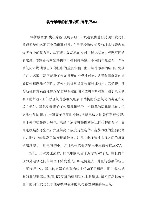
图1氧传感器2的外观。
工作原理氧传感器采用扁平结构的多层氧化锆陶瓷作为核心元件。
氧化锆元素的工作原理相当于一个简单的固体原电池。
根据电化学原理,由于氧离子浓度的不同,两侧电极之间会存在电位差。
由于外电极暴露于废气,氧离子浓度将根据实际工作条件而变化,而内电极是参考空气,并且氧离子浓度是恒定的。
当发动机的空燃比稀时,排气中的氧离子浓度相对较高,并且内电极和外电极之间的氧离子浓度差小,即电势差小,并且氧传感器的输出电压信号接近0V。
相反,当空燃比浓时,排气中的氧离子浓度相对较低,并且内电极和外电极之间的氧离子浓度差大,即电势差大,并且传感器的输出电压接近1V。
氧气传感器的典型响应曲线如下图所示。
图2氧传感器的典型响应曲线(在450℃发动机测功机上测量)3。
结构特点我公司生产的现代发动机管理系统中使用的氧传感器的主要特点是:l全球统一设计,全球采购系统能保证全球产品性能的一致性;也可根据客户图纸要求制作。
符合客户要求的L型氧传感器连接器具有防水功能。
我有很短的点火时间和快速反应。
l具有通用接口结构设计。
很容易满足不同客户的需求。
l具有超强的低温适应性。
l 具有超强的抗杂质中毒性能。
l设计可防止表面化合物烧结。
l使用不锈钢丝。
我工作可靠。
L具有防错设计,便于应用L独立接地设计。
系统工作稳定可靠。
性能参数和技术规格(发动机测功机在450℃下的测量值)空燃比浓时的电压信号:750毫伏升空燃比稀电压信号:当120毫伏升450℃时,空燃比变浓和变稀的相应时间:当150 ms升450℃时,对应的稀空燃比和浓空燃比的时间为:65毫秒升锆元素激活时间12秒升加热元素电阻(21℃) 9.6 1.5欧姆升加热元素电流:0.52±0.10安培升加热元件功率:7.0瓦升内阻:500欧姆升外部电压(连接至发动机控制模块控制器):12.0伏升氧传感器信号传输线束线径要求:1.6毫米l氧传感器典型匹配连接器由我公司生产。
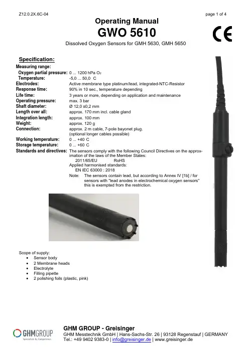
Operating ManualGWO 5610Dissolved Oxygen Sensors for GMH 5630, GMH 5650Specification:Measuring range:Oxygen partial pressure: 0 ... 1200 hPa O2Temperature:-5,0 ... 50,0 °CElectrodes:Active membrane type platinum/lead, integrated-NTC-ResistorResponse time:90% in 10 sec., temperature dependingLife time: 3 years or more, depending on application and maintenanceOperating pressure:max. 3 barShaft diameter:Ø 12,0 ±0,2 mmLength over all:approx. 170 mm incl. cable glandIntegration length:approx. 100 mmWeight:approx. 120 gConnection:approx. 2 m cable, 7-pole bayonet plug.(optional longer cables possible)Working temperature:0 ... +40°CStorage temperature: 0 ... +60°CStandards and directives:The sensors comply with the following Council Directives on the approx-imation of the laws of the Member States:2011/65/EU RoHSApplied harmonised standards:EN IEC 63000 : 2018Note: The sensors contain lead, but according to Annex IV [1b] / forsensors with "lead anodes in electrochemical oxygen sensors"this is exempted from the restriction.Scope of supply:∙Sensor body∙ 2 Membrane heads∙Electrolyte∙Filling pipette∙ 2 polishing foils (plastic, pink)GHM GROUP - GreisingerGHM Messtechnik GmbH | Hans-Sachs-Str. 26 | 93128 Regenstauf | GERMANYTel.: +49 9402 9383-0 | | www.greisinger.deDesign of Sensor GWO 5610Lifetime:At the end of the Lifetime, the signal of the sensor is dropping rapidly. The sensor evaluation in % therefore e can only be taken as a relative measure. An evaluation of 70% does not mean that 70% of lifetime is left, but that the electrode signal has 70% of a good state reference.Note: The sensor state evaluation will be stored after a successful calibration of the oxygen sensorThe nominal lifetime may be reduced due to the application. Negative effecting are:- Extreme storage and operation temperature- D irty water during measuring- Mechanical stress to sensor membrane- Dry storage of filled sensor- Permanent use at higher CO 2-concentrationsMounting/Operation Position:The optimum position is with sensor membrane pointing downwards.Measuring Precision: The precision can be influenced due to:- To less flow- Water and sensor temperature have to be the same, most exact measuring is done, when calibrated at measuring temperature.Generalfilling hole shaft membrane head platinum elec-trode protective flask The oxygen sensor is an active sensor. It consists of a platinum cathode, a lead an-ode and potassium hydroxide (KOH) as an electrolyte. If oxygen is present, it is re-duced on the platinum cathode and the sensor delivers a signal. If no oxygen is pre-sent, no signal is delivered. The anode is consumed by the oxygen measurement.The sensor ages. Furthermore, the sensor loses liquid through the permeable mem-brane, in particular, when it is stored in dry air. Therefore, it should be checked andmaintained regularly and replaced as necessary. (p.r.t. sensor maintenance)Make it a rule to always store the electrode in a humid environment- in the storage flask filled with water or- in another container filled with waterIf electrode has not been used for some time, clean membrane with softcloth and remove deposits, if any (algae, bacteria etc.).Attention: The membrane is delicate – if damaged, caustic electrolytegets lost and the sensor shows wrong signal. DesignThe electrode housing is made of ABS. With the exception of the electrode shaft all parts need to be maintained regularly and be replaced if necessary. o Protective flask : The protective flask is used to moisten the membrane. This prolongs service life of the electrode. The protective flask contains water. Attention ! Use water only; never use potassium chloride (KCI); this is only re-quired for storage of pH-electrode.o Membrane head : the membrane head is covered with a Teflon membrane. It will be filled with KOH electrolyte and screwed onto the electrode shaft (no airbubbles). Damages in the membrane, large air bubbles or air bubble rings in the membrane head will result in erroneous measurements. This may also be the rea-son for errors in the calibration.The membrane head (GWOK 02) is a spare part and can be ordered individually. o Filling hole : If the electrode is used at high temperatures or if it has been stored without its protective flask for a longer period of time, some electrolyte will be lostdue to evaporation. Please refer to Refilling description below.DANGER Attention when working with electrolyte: The electrolyte is caustic! (strong base, KOH) Avoid contact to skin, protect Your eyes !Visible Residues in the Inner of Membrane Head:As a reaction product in operation, there will be lead oxide (red and brown – from the reaction with oxygen) and lead carbonate (white – from the reaction of carbon dioxide) in the inner of the sensor.These substances may accumulate visibly at the membrane, but usually have now negative effect on the operability. Within a maintenance cycle the residues can be washed off the membrane nearly completely.Significant deposits on the membrane and matt platinum electrode.Deposits already have an effect on the measurement.=> Carry out maintenance to remove these.Slight deposits on the edge of the electrode, predominantly blank platinum elec-trode.No significant influences on the measurement to be expected.=> Maintenance not absolutely necessary.Deposits on the membrane, bare platinum electrode.=> no maintenance required.Polished platinum electrode during maintenance.Before screwing the membrane head on sensor body again they should be washed off, to avoid them getting in be-tween platinum cathode and membrane.A fast occurrence shortly after first filling or an unusual high amount of them (e.g. within some days) may be a sign of air in the sensor – either because of incorrect filling (bubbles), not sufficiently closing membrane head or filling screw or a leaking membrane.First start of operation of dry sensor GWO 5610 / Refilling of GWO 5610The GWO 5610 can be delivered dry as an option. Therefore the sensor is easily storable over a long time.The sensor has to be filled timely towards the measuring. After filling a time of ~ 2 hours has to be considered, until the sensor has stabilized.Wear suitable gloves*) and protect your eyes with safety goggles when filling the electrolyte!Do not touch the electrolyte with bare skin, if there was contact rinse sufficiently with water.Material:∙Sensor GWO 5610 with membrane head∙Filling-pipette∙Electrolyte KOH∙Flat blade screw driver∙Paper towel∙Suitable gloves *), safety goggles∙Wash basinFirst Filling:∙Check membrane head GWOK 02: is it in good state? Is Mem-brane undamaged?∙Open filling screw∙Fill pipette with KOH∙First fill the membrane head up to ¾ of its height, screw onmembrane head tightly, rinse excess KOH with water.∙Then carefully fill the sensor, try to flick at the shaft from time totime, helping air bubbles coming out. In sum the sensor fillingtakes around 5 ml.∙If there are no more air bubbles and the filling hole is full, closewith filling screw.∙Rinse excess KOH with waterFigure: Filling with pipette ∙Turn sensor upwards: Are air bubbles visible below the mem-brane? If so: Refill once again.∙Wait approximately 2 hours for the sensor to stabilize, afterwards calibrate the sensor – the electrode state evaluation should deliver 100%.*) suitable gloves: Acc. to DIN EN 420, e.g. natural latex, natural rubber, butyl rubber, nitrile rubber,polychloroprene, fluorinated rubber.Sensor Maintenance of GWO 5610If the sensor can no more be calibrated or only unstable values are displayed, it has to be maintained or even or the membrane head has to be exchanged.Wear suitable gloves*) when filling the electrolyte! Do not touch the electrolyte with bare skin. If there was contact rinse sufficiently with water.Material:∙Sensor GWO 5610, eventually spare membrane head GWOK 02∙Filling pipette∙Electrolyte KOH∙Flat blade screw driver∙Paper towel∙Polishing foil (pink)∙Suitable gloves *), Safety goggles∙Wash basinMaintenance is basically the same as the first filling, but first the membrane head is unscrewed and the old electro-lyte is removed.Unscrew the membrane head and the refill opening - Attention! Old electrolyte will now leak out!If the membrane is undamaged and free of deposits, the membrane head can be used again.The platinum electrode must be bright and free of deposits!Wipe off existing deposits from the platinum electrode with a cloth, if necessary polish the electrode using the pink polishing foil.The filling of the sensor is like described bevor.Hints for Operation:a.) Treat device and sensor carefully. Use only in accordance with above specification. (do not throw, hit againstetc.). Protect plug and socket from soiling.b.) The electrode are only suitable for the devices GMH5630, 5650. Unsuitable devices may lead to the destructionof the measuring device and the oxygen sensor.c.) A protective cap, such as GSKA 3600 in plastic or GSKA 3610 in red bronze is recommended for protection ofthe membrane, e.g. for use in bodies of water.Safety guidelines:This device has been designed and tested in accordance with the safety regulations for electronic devices. However, its trouble-free operation and reliability cannot be guaranteed unless the standard safety measures and special safety advises given in this manual will be adhered to when using the device.1. Trouble-free operation and reliability of the device can only be guaranteed if the device is not subjected to anyother climatic conditions than those stated under "Specification".2. Do not use these products as safety or emergency stop devices or in any other application wherefailure of the product could result in personal injury or material damage.Failure to comply with these instructions could result in death or serious injury and material dam-age.3. Attention, caustic! The sensor contains KOH electrolyte (Potassium Hydroxide).KOH may cause burns!Avoid the contact to leaking liquid!When there was contact:- to skin: immediately flush with water for several minutes- to clothing: take of affected clothing.- to the eyes flush with water for several minutes, get medical aid.In case of ingestion:Drink plenty of water immediately, do not induce vomiting! Get medical aid.Disposal instructionsThe electrode contains lead and corrosive electrolytic liquid and must not be disposed of in theresidual waste bin. Do not dispose of together with batteries, risk of explosion!Return it to us, freight prepaid. We will then arrange for the proper and environmentally-friendlydisposal.Private end users in Germany have the possibility of dropping off the product at the municipalcollection centre。
氧传感器使用说明书 (第一版)适用零件号:25327985 253599081.概述氧传感器是现代发动机管理系统中必不可少的重要零部件。
它是一种利用电化学工作原理发展出来的电器元件。
氧传感器在现代发动机管理系统的配置机构中被用于探测汽车发动机所排出的燃烧废气中氧的含量,借以判定发动机实时燃油供给空气燃料混合比的实际状态,并通过自身产生的电器反应信号反馈给发动机电子控制模块(ECM),以作为系统燃油管理系统的闭环燃油修正补偿控制的重要依据,使燃油管理子系统能够更加精确地控制调整发动机各种工作状态下的空气燃料混合比;并在绝大多数工况下使系统保持在理想空燃比工作状态,以便获得更加优良的汽车排放控制特性和燃油经济性。
氧传感器的输出信号为0 ~ 1V的交变电压信号。
传感器可根据发动机所排燃烧气中氧的含量高低自动感应和探测并向发动机电子控制模块输出这一高低变化的电压信号。
现代发动机管理系统采用的氧传感器有两种主要类型:非加热型氧传感器和加热型氧传感器。
装配在发动机排气歧管上的氧传感器,由于可以利用发动机所排出燃烧废气的余热进行快速加热,故可使用价格低廉的非加热型氧传感器;当氧传感器的安装位置受到整车布置限制,氧传感器距离发动机排气歧管出口较远时,由于不能利用发动机燃烧废气对于传感器迅速加热,此时必然需要采用加热式氧传感器。
加热式氧传感器的内部设计有热敏电加热元件,可利用系统供电电压强制使氧传感器加速预热,促使其快速起燃,及早实现系统的闭环燃油管理控制。
2. 工作原理德尔福公司生产的氧传感器是采用氧化锆元件作为传感器的基础元件。
氧化锆元件是一种通体充满无数微孔的陶瓷基础元件外面镀有氧化锆涂层,该涂层外测暴露于发动机燃烧废气之中;涂层的内侧透过含微孔的陶瓷元件与大气相通。
集中在氧化锆内外两侧电极之间氧含量的差别形成的微分电压信号。
当氧化锆元件被电流加热或被流经传感器的发动机燃烧废气加热所激活,空气经过通体充满无数微孔的陶瓷基础元件进入氧化锆元件的内电极,而燃烧废气流经氧化锆的外电极。
Instruction manual O2Transmitter 4100 eOrder number: 52 121 114ContentsMettler-Toledo GmbH, Process Analytics, Industrie Nord,CH-8902 Urdorf, Tel. (01) 736 26 36Subject to technical changes. Mettler-Toledo GmbH, 10/03.WarrantyDefects occurring within 1 year from delivery date shall be remedied free of charge at our plant (carriage and insurance paid by sender).Subject to change without noticeDisposal (Directive 2002/96/EC of January 27, 2003)Please observe the applicable local or national regulations concerning the disposal of “waste electrical and electronic equipment”.ContentsSafety information Array Be sure to read and observe the following instruc-tions!The device has been designed in accordance with the state ofthe art and complying with the applicable safety regulations.When operating the device, certain conditions may neverthe-less lead to danger for the operator or damage to the device.Caution!Commissioning may only be carried out by trained experts.Whenever it is likely that protection has been impaired, thedevice shall be made inoperative and secured against unintend-ed operation.The protection is likely to be impaired if, for example:•the device shows visible damage•the device fails to perform the intended measurements•after prolonged storage at temperatures above 70 °C•after severe transport stressesBefore recommissioning the device, a professional routine testin accordance with EN 61010-1 must be performed. This testshould be carried out by the manufacturer.Intended useThe O2Transmitter 4100 e is used for dissolved oxygen and tem-perature measurement in biotechnology, pharmaceutical industry, as well as in the field of environment, food processing, and sewage treatment.The rugged molded enclosure can be wall or pipe mounted or fixed into a control panel.The protective hood provides additional protection against direct weather exposure and mechanical damage.The Transmitter has been designed for application with ampero-metric sensors of the InPro6000 ... InPro6800 Series. TrademarksThe following names are registered trademarks. For practical rea-sons they are shown without trademark symbol in this manual. InPro®EasyClean®EC Declaration of conformityOverview of O 2Transmitter 4100 eDo not connect!CathodeGuardAnodeReference electrode RTDRTDshieldHOLD HOLD/CONTROL CONTROL+ Output 1- Output 1/2+ Output 2Relay 1Relay 1/2Relay 2AlarmAlarmClean Clean Power PowerPackage contentsCheck the shipment for transport damage and completeness. The package should contain:• Front unit• Lower case• Bag containing small parts• Instruction manual• Specific test reportAssemblyFig.: Pipe-mount kitPipe mounting, panel mountingInstallation and connectionCaution!•Installation may only be carried out by trained experts in accordance with this instruction manual and as per applicable local and national codes.•Be sure to observe the technical specifications and input ratings.•Be sure not to notch the conductor when stripping the insulation.•Before connecting the device to the power supply, make sure that its voltage lies within the range 20.5 to 253 V AC/DC.•When commissioning, a complete configuration must be carried out by the system administrator.The terminals are suitable for single wires and flexible leads upto 2.5 mm2(AWG 14)Warning!Additional safety precautions have to be taken for applications in hazardous locations to CSA (CLI DIV2 GPA,B,C,D T4, Ex nA IIC T4)!(See Pg 93.)Protective wiring of switching contactsRelay contacts are subjected to electrical erosion. Especially with inductive and capacitive loads, the service life of the con-tacts will be reduced. For suppression of sparks and arcing,components such as RC combinations, nonlinear resistors,series resistors and diodes should be used.Protective wiringA: DC application with inductive loadB: AC/DC applications with capacitive load C: Connection of incandescent lampsA1Inductive loadA2Free-wheeling diode, e.g. 1N4007 (Observe polarity)A3ContactB1Capacitive loadB2Resistor, e.g. 8 Ohms/1 W at 24 V / 0.3 A B3ContactC1Incandescent lamp, max 60 W / 230 V , 30 W / 115 V C3ContactWarning!Make sure that the maximum ratings of the relay contacts are not exceeded even during switching!Typical protective wiring measuresProtective wiringUser interface, displayDisplayOperation: KeypadSensocheck, Sensoface sensor monitoringSensocheck continuously monitors the sensor and leads.Sensocheck can be switched off (Configuration, Pg 46).Safety featuresMode codesThe mode codes allow fast access to all functions CalibrationOverview of configuration stepsNote:The Transmitter 4100 e has a device a resolution of 0.01 ppm. For the sensor type B, we recommend the O2Transmitter 4100ppb with a device resolution of 0.001 ppm.Polarization voltage. Process pressure. Salt correction.Two complete parameter sets are stored in the EEPROM. As delivered, the two sets are identical but can be edited. Note:Fill in your configuration data on the following pages.Default settings of parameter setsCode. Parameter Setting o1. Sensor type ________________________o1. %, mg/l, ppm ________________________o1. 0/4-20 mA________________________o1. Current beginning ________________________o1. Current end ________________________o1. Filter time ________________________o1. 22mA signal ________________________o1. Hold behavior ________________________o1. Fix current ________________________o2. Unit °C / °F ________________________o2. Temp probe ________________________o2. 0/4...20mA________________________o2. Current beginning ________________________o2. Current end ________________________o2. Filter time ________________________o2. 22mA signal ________________________o2. Hold behavior ________________________o2. Fix current________________________Co. Polarization voltage ________________________Co. Pressure unit ________________________Co. Pressure ________________________Co. Salinity ________________________CA. Cal mode ________________________CA. Cal interval ________________________AL. Sensocheck ________________________AL. Alarm delay ________________________AL. LED Hold________________________Parameter set – user settingsCode. Parameter Setting rL. Relay function ________________________L1. Contact function ________________________L1. Contact response ________________________L1. Switching point ________________________L1. Hysteresis ________________________L1. Delay________________________L2. Contact function ________________________L2. Contact response ________________________L2. Switching point ________________________L2. Hysteresis ________________________L2. Delay________________________Ct. Setpoint ________________________Ct. Neutral zone ________________________Ct. P action ________________________Ct. I action ________________________Ct. D action________________________Ct. PLC/PFC controller ________________________Ct. Pulse length ________________________Ct. Pulse frequency ________________________Ct. Hold behavior ________________________Pb. Probe selection ________________________Pb. Rinsing interval ________________________Pb. Rinse duration ________________________Pb. Contact type ________________________Pb. Cleaning interval________________________Pb. Lock cleaning interval________________________It is always recommended to calibrate in air.Compared to water, air is a calibration medium which is easy to handle, stable, and thus safe. In the most cases, however, the sensor must be dismounted for a calibration in air.When dealing with biotechnological processes which require sterile conditions, the sensor cannot be removed for calibration. Here, calibration must be performed with aeration directly in the process medium (e.g. after sterilization).The calibration procedures for these two common applications are described on the following pages. Of course, other combina-tions of process variable and calibration mode are possible.Note:When a 2-point calibration is required, the zero point calibration should be performed prior to saturation or concentration cali-bration, resp.All calibration procedures must be performed by trainedpersonnel.Zero point calibrationNote:In Hold mode the controller output acts as configured (Y = const. or Y = 0).50 %X w10 / (1.00)20 / (2.00)30 / (3.00)40 / (4.00)50 / (5.00) ControlleroutputYProportional action (Gradient K C[%])Neutral zone (Y=0)Tolerated deviation from setpoint.The setting “010%”, for example, permits a deviation of ±5 % from the desired value without activating the controller.Pulse length / pulse frequency controllerPulse length controller (PLC)The pulse length controller is used to operate a valve as an actuator. It switches the contact on for a time that depends on the controller output. The period is constant. A minimum ON time of 0.5 sec is maintained even if the controller output takes corresponding values.Pulse frequency controller (PFC)The pulse frequency controller is used to operate a frequency-controlled actuator. It varies the frequency with which the contacts are switched on. The maximum pulse frequency [pulses/min] can be defined. It depends on the actuator.The Contact ON time is constant. It is automatically calculated from the user-defined maximum pulse frequency:Output signal (switching contact) of pulse frequency controllerOutput signal (switching contact) of pulse length controllerOperation with automatic cleaning system“EasyClean” is a separate automatic cleaning system. The cleaning cycle is activated according to the cleaning interval defined during configuration (Pg 55).Calibration error messagesNoteThe worsening of a Sensoface criterion leads to the devaluation of the Sensoface indicator (Smiley becomes “sad”). An improvement of the Sensoface indicator can only take place after calibration or removal of a sensor defect.SensocheckContinuously monitors the sensor and lines for short circuits or open circuits. Critical values make the Sensoface “sad” and the corresponding icon flashes:The Sensocheck message is also output as error messageErr33. The alarm contact is active, the red LED is lighted, out-put current 1 is set to 22 mA (when configured corresponding-ly). Sensocheck can be switched off during configuration (then Sensoface is also disabled). Exception: After a calibration aAppendixProduct line and accessoriesDevices Order No. O2Transmitter 4100 e52 121 103 Mounting accessoriesPipe-mount kit52 120 741 Panel-mount kit52 120 740 Protective hood52 120 739 SensorsMettler-Toledo GmbH, Process Analytics offers a wide range of sensors for the following fields of applications:- Chemical process industry- Pharmaceutical industry- Food and beverage industry- Water/waste-waterFor more information concerning our sensors and housings program, please refer to .DO input Sensor Type A: InPro6000 – 6800Sensor Type B:InPro6900Measuring current-2 to 1800 nA,Resolution 0.05nA(with Vpol = 800 mV and Vref = 200 mV)Saturation (-10 to 80 °C)0 to 500 %Meas. error1,2,30.5 % meas.val. + 0.5 %Concentration (-10 to 80 °C)0.00 to 50.00 mg/l0.00 to 50.00 ppmMeas. error1,2,30.5 % meas.val. + 0.05 mg/lor 0.05 ppmAdm. guard current≤20 µAPolarization voltage*0 to 1000 mV,Process pressure *0.000 to 9.999 bars(to 999.9 kPa / to 145.0 psi)Salt correction *00.00 to 45.00 g/kgSensor standardizationOperating modes *DO saturation (automatic)DO concentration (automatic)Product calibrationZero point calibrationCalibration range Zero point±2 nASensor Type A Slope25 to 130 nA(at 25 °C, 1013 mbars)Calibration range Zero point±2 nASensor Type B Slope200 to 550 nA(at 25 °C, 1013 mbars)Calibration timer *0000 to 9999 hPressure correction *0.000 to 9.999 bars / 999.9 kPa / 145.0 psiSensocheck Monitoring for short circuits / open circuits (can be disabled)Sensoface Provides information on the sensor conditionEvaluation of zero/slope, response,calibration interval, Sensocheck Temperature NTC 22 kOhms / NTC 30 kOhms, selectableinput2-wire connection, adjustableMeasurement range-20.0 to +150.0 °C / -4 to +302 °FAdjustment range10 KResolution0.1 °C / 1 °FMeas. error1,2,3< 0.5 K (<1 K at > 100°C)HOLD input Galv. separated (OPTO coupler)Function Switches Transmitter to HOLD modeSwitching voltage Inactive0 to 2 V (AC/DC)Active10 to 30 V (AC/DC) CONTROL input Galv. separated (OPTO coupler)Function Control input for automatic cleaning system Switching voltage Inactive0 to 2 V (AC/DC)Active10 to 30 V (AC/DC) Output 10/4 to 20 mA, max. 10 V, floating(galv. connected to output 2)Process variable *DO saturation/DO concentrationOverrange *22 mA in the case of error messagesOutput filter *Low-pass, filter time constant 0 to 120 sMeas. error 1< 0.3 % current value + 0.05 mAStart/end of scale Configurable within selected rangeAdm. span 5 to 500 % / 0.5 to 50 mg/l (ppm)Output 20/4 to 20 mA, max. 10 V, floating(galv. connected to output 1)Process variable TemperatureOverrange *22 mA in case of temp error messagesOutput filter *Low-pass, filter time constant 0 to 120 sMeas. error 1< 0.3 % current value + 0.05 mAStart/end of scale*-20 to +150 °C / -4 to +302 °FAdm. span 20 to 170 K (68 to 338 °F)Alarm contact Relay contact, floatingContact ratings AC< 250 V / < 3 A / < 750 VADC< 30 V / < 3 A / < 90 WContact response N/C (fail-safe type)Response delay *0000 to 0600 sLimit values Output via relay contacts R1, R2Contacts R1, R2 floating but inter-connected Contact ratings AC< 250 V / < 3 A / < 750 VADC< 30 V / < 3 A / < 90 WContact response*N/C or N/OResponse delay *0000 to 0600 sSwitching points*Within selected rangeHysteresis*000.0 to 050.0 % / 00.00 to 05.00 mg/l (ppm)PID Output via relay contacts R1, R2process controller(Relay R1: below setpoint,Relay R2: above setpoint)Setpoint specification*0 to 500 % / 0.00 to 50.00 mg/l (ppm)Neutral zone*000.0 to 050.0 % / 00.00 to 05.00 mg/l (ppm)P-action component*Controller gain Kp: 0010 to 9999 %I-action component*Reset time Tr:0000 to 9999 s(0000 s = no integral action) D-action component*Rate time Td: 0000 to 9999 s(0000 s = no derivative action) Controller type*Pulse length controller or pulse frequency controller Pulse period*0001 to 0600 s, min. ON time 0.5 s(pulse length controller)Max. pulse frequency*0001 to 0180 min-1(pulse frequency controller)Cleaning function*Relay contact, floating, for controlling a simple rinsingsystem or an automatic cleaning system (EasyClean) Contact ratings AC< 250 V / < 3 A / < 750 VADC< 30 V / < 3 A / < 90 WContact response*N/C or N/OInterval *000.0 ... 999.9 h(000.0 h = cleaning function switched off)Rinse duration*0000 ... 1999 sDisplay LC display, 7-segment with iconsMain display Character height 17 mm, unit symbols 10 mm Secondary display Character height 10 mm, unit symbols 7 mmSensoface 3 status indicators (friendly, neutral, sad Smiley)Mode indicators 5 status bars“meas”, “cal”, “alarm”, “cleaning”, “config”18 further icons for configurationand messagesAlarm indication Red alarm LED in case of alarm or HOLD (user defined) Keypad 5 keysService functionsCurrent source Current specifiable for output 1 and 2 (00.00 to 22.00 mA) Manual controller Controller output entered directly (start of control process) Device self-test Automatic memory test (RAM, FLASH, EEPROM)Display test Display of all segmentsLast Error Display of last error occurredSensor monitor Display of direct, uncorrected sensor signalRelay test Manual control of the four switching contactsParameter sets Two selectable parameter sets for differentapplicationsData retention Parameters and calibration data > 10 years (EEPROM)Protection against Protective separation of all extra-low-voltage circuits against electrical shock mains by double insulation as per EN 61010-1Power supply24 (-15%) to 230 V AC/DC (+10%); approx. 5 VA, 2.5 WAC: 45 to 65 Hz; Overvoltage category II, Class IINominal operating conditionsAmbient temperature-20 to +55 °CTransport/Storage temp.-20 to +70 °CRelative humidity 10 to 95 % not condensingPower supply24 (-15%) to 230 V AC/DC (+10%)Frequency for AC45 to 65 HzEMC EN 61326Emitted interference Class B (residential environment)Class A for mains supply > 60 V DCImmunity tointerference IndustrialenvironmentExplosion protectionFM: NI Class I Div 2 Group A, B, C & D,T4T a = 55 °C; T ype 2NI Class I Zone 2Group IIC,T4 T a = 55°C; T ype 2CSA:Class I Div 2 Groups A, B, C and D,T4Ex nA IIC T4Enclosure Molded enclosure made of PBT (polybutylene terephtalate) Color Bluish gray RAL 7031Assembly• Wall mounting• Pipe mounting: dia 40 to 60 mm, 30 to 45 mm• Panel mounting, cutout to DIN 43 700Sealed against panelDimensions H 144 mm, B 144 mm, T 105 mmIngress protection IP 65 / NEMA 4XCable glands 3 breakthroughs for cable glands M20x1.52 breakthroughs for NPT 1/2 “orRigid Metallic ConduitWeight Approx. 1 kg*) User-defined) To IEC 746 Part 1, at nominal operating conditions) ±1 count) Plus sensor errorExplosion protectionWarnings and notesto ensure safe operation2-point calibration . . . . . . . . . . . . . . . . . . . . . . . . . . . . . .6122 mA signal for error message . . . . . . . . . . . . . .37, 43, 78Accessories . . . . . . . . . . . . . . . . . . . . . . . . . . . . . . . . . . . .85Alarm settings . . . . . . . . . . . . . . . . . . . . . . . . . . . . . . . . . .46Alarm contact . . . . . . . . . . . . . . . . . . . . . . . . .46, 88, 78Alarm delay . . . . . . . . . . . . . . . . . . . . . . . . . . . . . . . . . 47Error messages . . . . . . . . . . . . . . . . . . . . . . . . . . . . . . .78Operating states . . . . . . . . . . . . . . . . . . . . . . . . . . . . . .80Assembly . . . . . . . . . . . . . . . . . . . . . . . . . . . . . . . . . . . . .10Cal timer . . . . . . . . . . . . . . . . . . . . . . . . . . . . . . . . . . . . . .47Calibration . . . . . . . . . . . . . . . . . . . . . . . . . . . . . . . . . . . .61Calibration to concentration (Conc) . . . . . . . . . . . . . . . .64Calibration to saturation (SAT) . . . . . . . . . . . . . . . . . . . .62Display of calibration data . . . . . . . . . . . . . . . . . . . . . . .71Specify calibration mode . . . . . . . . . . . . . . . . . . . . . . . .47Cleaning system . . . . . . . . . . . . . . . . . . . . . . . . . . . . . . . .77Configuration . . . . . . . . . . . . . . . . . . . . . . . . . . . . . . . .54Lock cleaning interval . . . . . . . . . . . . . . . . . . . . . . . . . .54Configuration . . . . . . . . . . . . . . . . . . . . . . . . . . . . . . . . . .26Configuration steps . . . . . . . . . . . . . . . . . . . . . . . . . . . .28Menu structure . . . . . . . . . . . . . . . . . . . . . . . . . . . . . . .27Configuration: Alarm settings . . . . . . . . . . . . . . . . . . . . . .46Alarm delay . . . . . . . . . . . . . . . . . . . . . . . . . . . . . . . . . .47LED in HOLD mode . . . . . . . . . . . . . . . . . . . . . . . . . . . .47Sensocheck . . . . . . . . . . . . . . . . . . . . . . . . . . . . . . . . . .47Configuration: Correction . . . . . . . . . . . . . . . . . . . . . . . . .44Polarization voltage . . . . . . . . . . . . . . . . . . . . . . . . . . . .44Process pressure . . . . . . . . . . . . . . . . . . . . . . . . . . . . . .44Salt correction . . . . . . . . . . . . . . . . . . . . . . . . . . . . . . . .44Configuration: Calibration mode . . . . . . . . . . . . . . . . . . .46Cal timer interval . . . . . . . . . . . . . . . . . . . . . . . . . . . . . .47Configuration: Controller . . . . . . . . . . . . . . . . . . . . . . . . .52IndexConfiguration: Limit function . . . . . . . . . . . . . . . . . . . . . .48Settings for relay 1 . . . . . . . . . . . . . . . . . . . . . . . . . . . .48Settings for relay 2 . . . . . . . . . . . . . . . . . . . . . . . . . . . .50Use of relays . . . . . . . . . . . . . . . . . . . . . . . . . . . . . . . . .49Configuration: Output 1 . . . . . . . . . . . . . . . . . . . . . . . . . .30Measurement procedure . . . . . . . . . . . . . . . . . . . . . . . .30Output current during Error . . . . . . . . . . . . . . . . . . . . . .36Output current range . . . . . . . . . . . . . . . . . . . . . . . . . .32Output signal during HOLD . . . . . . . . . . . . . . . . . . . . . .37Select sensor type . . . . . . . . . . . . . . . . . . . . . . . . . . . . .30Time constant of output filter . . . . . . . . . . . . . . . . . . . . .34Configuration: Output 2 . . . . . . . . . . . . . . . . . . . . . . . . . .38Output current during HOLD . . . . . . . . . . . . . . . . . . . . .42Set output current range . . . . . . . . . . . . . . . . . . . . . . . .39Temperature error . . . . . . . . . . . . . . . . . . . . . . . . . . . . .42Temperature probe . . . . . . . . . . . . . . . . . . . . . . . . . . . .39Temperature unit . . . . . . . . . . . . . . . . . . . . . . . . . . . . . .38Time constant of output filter . . . . . . . . . . . . . . . . . . . .40Configuration: Rinsing and calibration probes . . . . . . . . . .54Control drawing . . . . . . . . . . . . . . . . . . . . . . . . . . . . .94, 96Controller . . . . . . . . . . . . . . . . . . . . . . . . . . . . . . . . . . . . .74Configuration . . . . . . . . . . . . . . . . . . . . . . . . . . . . . . . .62Controller equations . . . . . . . . . . . . . . . . . . . . . . . . . . .75Controller test . . . . . . . . . . . . . . . . . . . . . . . . . . . . . . . .73Pulse length / pulse frequency controller . . . . . . . . . . . .74Controller: behavior during HOLD . . . . . . . . . . . . . . . . .53Current source 1/2 . . . . . . . . . . . . . . . . . . . . . . . . . . . . . .72Diagnostics functions . . . . . . . . . . . . . . . . . . . . . . . . . . . .71Controller test . . . . . . . . . . . . . . . . . . . . . . . . . . . . . . . .73Display of calibration data . . . . . . . . . . . . . . . . . . . . . . .71Display of last error message . . . . . . . . . . . . . . . . . . . . .71Display of output currents . . . . . . . . . . . . . . . . . . . . . . .71Display of sensor current . . . . . . . . . . . . . . . . . . . . . . . .71。
Brief Operating InstructionsOxymax W COS41Dissolved oxygen sensorThese instructions are Brief Operating Instructions.For detailed information, please read the Operating Instructions and the special instructions on the supplied CD-ROM.The complete device documentation comprises:•these Brief Operating Instructions•the Operating Instructions on the supplied CD-ROM•if necessary, certificates and calibration protocols (acc. to the version).KA284C/07/en/06.0571002048Table of contents Oxymax W COS41 Table of contents1 Safety instructions. . . . . . . . . . . . . . . . . . . . . . . . . . . . . . . . . . . . . . . . . . . . . . . . . 21.1 Designated use . . . . . . . . . . . . . . . . . . . . . . . . . . . . . . . . . . . . . . . . . . . . . . . . . . . . . . . . . . . . . . . . . . . . . . . . . . 21.2 Installation, commissioning and operation . . . . . . . . . . . . . . . . . . . . . . . . . . . . . . . . . . . . . . . . . . . . . . . . . . . . . . 21.3 Operational safety . . . . . . . . . . . . . . . . . . . . . . . . . . . . . . . . . . . . . . . . . . . . . . . . . . . . . . . . . . . . . . . . . . . . . . . . 32 Installation. . . . . . . . . . . . . . . . . . . . . . . . . . . . . . . . . . . . . . . . . . . . . . . . . . . . . . 32.1 Installation conditions . . . . . . . . . . . . . . . . . . . . . . . . . . . . . . . . . . . . . . . . . . . . . . . . . . . . . . . . . . . . . . . . . . . . . 32.2 Installation instructions . . . . . . . . . . . . . . . . . . . . . . . . . . . . . . . . . . . . . . . . . . . . . . . . . . . . . . . . . . . . . . . . . . . . 42.3 Installation examples . . . . . . . . . . . . . . . . . . . . . . . . . . . . . . . . . . . . . . . . . . . . . . . . . . . . . . . . . . . . . . . . . . . . . 52.4 Post installation check . . . . . . . . . . . . . . . . . . . . . . . . . . . . . . . . . . . . . . . . . . . . . . . . . . . . . . . . . . . . . . . . . . . . 83 Wiring . . . . . . . . . . . . . . . . . . . . . . . . . . . . . . . . . . . . . . . . . . . . . . . . . . . . . . . . . 93.1 Direct connection to the transmitter . . . . . . . . . . . . . . . . . . . . . . . . . . . . . . . . . . . . . . . . . . . . . . . . . . . . . . . . . . 93.2 Connection via junction box . . . . . . . . . . . . . . . . . . . . . . . . . . . . . . . . . . . . . . . . . . . . . . . . . . . . . . . . . . . . . . . 104 Commissioning. . . . . . . . . . . . . . . . . . . . . . . . . . . . . . . . . . . . . . . . . . . . . . . . . . 114.1 Function check . . . . . . . . . . . . . . . . . . . . . . . . . . . . . . . . . . . . . . . . . . . . . . . . . . . . . . . . . . . . . . . . . . . . . . . . . 114.2 Polarization . . . . . . . . . . . . . . . . . . . . . . . . . . . . . . . . . . . . . . . . . . . . . . . . . . . . . . . . . . . . . . . . . . . . . . . . . . . 114.3 Calibration . . . . . . . . . . . . . . . . . . . . . . . . . . . . . . . . . . . . . . . . . . . . . . . . . . . . . . . . . . . . . . . . . . . . . . . . . . . . 121Safety instructions1.1Designated useThe oxygen sensor is suitable for continuous measurement of dissolved oxygen in water.Typical applications are:•Measuring, monitoring and regulating the oxygen content in activated sludge basins.•Monitoring the oxygen content in the sewage treatment plant outlet.•Monitoring, measuring and regulating the oxygen content in public waters and fish farming water.•Monitoring of oxygen enrichment in drinking water.Any other use than the one described here compromises the safety of persons and the entire measuring system and is, therefore, not permitted.The manufacturer is not liable for damage caused by improper or non-designated use.1.2Installation, commissioning and operation•The device/measuring system may only be installed, connected, operated and maintained by trained technical personnel (e.g. certified electrician). The technical personnel must strictlyadhere to the Operating Instructions, prevailing standards, legal regulations and certificates(depending on application).•If the Brief Operating Instructions do not provide sufficient information, you must read theOperating Instructions. There, you can find detailed information on the device.2Endress+HauserOxymax W COS41InstallationEndress+Hauser 3•The operator may only perform modifications and repairs of the device/measuring system that are explicitly permitted in the Operating Instructions.•Do not operate damaged products and secure them against unintentional commissioning. Mark the damaged product as being defective.•If faults can not be rectified, the products must be taken out of service and secured against unintentional commissioning.1.3Operational safetyThe sensor has been designed and tested according to the state of the art and left the factory in perfect functioning order.Relevant regulations and European standards have been met.As the user, you are responsible for complying with the following safety conditions: •Installation instructions•Local prevailing standards and regulations."Caution!Pay attention to the technical data on the name plate!2Installation2.1Installation conditions2.1.1OrientationOther angles are not permitted. Do not install the sensor overhead.Fig. 1: Angle of installation ARecommended angle of installation: 0 ... 180 °Installation Oxymax W COS414Endress+Hauser2.1.2Mounting location•Select the installation location so that there is easy access for later calibration.•Make sure that upright posts and assemblies are secured safely and vibration-free.•For immersed operation in an activated sludge basin, select an installation location which produces a typical oxygen concentration.2.2Installation instructions2.2.1Installing a measuring point!Note!For immersed operation, install the individual modules away from the basin on a solid base. Only carry out the final installation at the intended installation location.For a complete installation of a measuring point, proceed as follows:1.Install a retractable or a flow assembly (if used) into the process.2.Connect the water supply to the rinse connections (if you use an assembly with cleaning function).3.Install and connect the oxygen sensor.4.Install an immersion or an suspension assembly (if used) into the process."Caution!•For immersed operation, the sensor must be installed in an immersion assembly (e.g. CYA611). Do not install the sensor suspended from the cable.•Screw the sensor into the assembly so that the cable is not twisted.•Avoid exerting excessive tensile force on the cable (e.g. from jerky pulling).•Select the installation location so that there is easy access for later calibration.#Warning!When using metallic assemblies and installation equipment, comply with national grounding regulations.Oxymax W COS41InstallationEndress+Hauser 52.3Installation examples2.3.1Immersion operationUniversal assembly holder and chain assemblyFig. 2: CYH101 with immersible pendulum assembly 1Weather protection cover2Upright post, square pipe SS AISI 3043Transverse pipe SS AISI 3044Star handle5Second fixing possibility for transverse pipe 6Immersion assembly CYA 611Fig. 3: Immersion assembly CYA 6111Protection cap2Worm drive hose clip3Pipe clips (detailed drawing in right half)4PVC pipe5Threaded couplingInstallation Oxymax W COS41 Universal assembly holder and fixed immersion assemblyFig. 4: Universal suspension assembly holder CYH101 with immersion assembly CYY1051Star handle2Pipe holder3Fixing bracket4Immersion assembly (= immersion tube)6Endress+HauserOxymax W COS41InstallationEndress+Hauser 7Basin rim mounting with immersion tubeFloating bodyFig. 5: Horizontal basin rim mounting 1Protection cover for cable entry 2Assembly holder3Immersion assembly SS 1.4301 (AISI 304)Fig. 6: Vertical basin rim mounting 4Basin rim mounting 5Star handleFig. 7: Floating body1234567Cable route with strain relief and rain protection Mounting ring for ropes and chains with locking screwLugs Ø15, 3 x 120 ° for anchoring Saltwater-resistant plastic floatPipe 40x1, stainless steel 1.4571 (AISI 316Ti)Shock absorber and weight Oxygen sensorInstallation Oxymax W COS418Endress+Hauser2.3.2Flow assembly2.4Post installation check•Check the membrane for leak tightness und replace it if necessary.•Sensor and cable undamaged?•Compliance with permissible sensor installation position?•Is the sensor installed in an assembly and is not suspended from the cable?•Avoid moisture by rain by fitting the protective cap to the immersion assembly?Fig. 8: Flow assembly COA250-B 1Screw-in part for sensor 2Screw ring 3Meter body4Connection thread G¾5Dummy plug (connection for spray head COR3)Fig. 9: Bypass installation1Main line 2Medium return 3Oxygen sensor4, 7Manually actuated or solenoid valves 5Flow assembly COA250-B 690 ° pipe bracket 8Medium removalOxymax W COS41WiringEndress+Hauser 93Wiring#Warning!•The electrical connection must only be carried out by a certified electrician.•Technical personnel must have read and understood the instructions in this manual and must adhere to them.•Ensure that there is no voltage at the power cable before beginning the connection work.3.1Direct connection to the transmitterThe sensor is connected using a special measuring cable (→å 10). The wiring diagram is contained in the Operating Instructions of the COM223/253-DX/DS transmitter.!Note!The interior white and yellow pilot wires have no function.Fig. 10: Special measuring cable CYK 71Terminal S 12909111AssignmentOuter shieldActive inner shield (NTC)Cathode AnodeNTC temperature sensorWiring Oxymax W COS413.2Connection via junction boxTo lengthen the sensor connection beyond the length of the fixed cable, you require a junction box VBM. The connection is lengthened to the transmitter using the special measuring cable CYK71.Fig. 11: Connection via junction box VBM1Sensor2Junction box3Extension cable4Transmitter10Endress+HauserOxymax W COS41CommissioningEndress+Hauser 114Commissioning 4.1Function checkBefore first commissioning, check if:•the sensor is correctly installed•the electrical connection is correct.If using an assembly with automatic cleaning, check the correct water connection at theassembly rinse connection.#Warning!Danger of medium leaking offBefore applying compressed air to an assembly with cleaning facility, make sure the connections are correctly fitted. Otherwise, the assembly may not be insert into the process.4.2PolarizationThe sensor was tested in the factory for perfect functionality and is supplied ready for operation.To prepare for calibration, proceed as follows:1.Remove the sensor protective cap.2.Place the externally dry sensor in atmospheric air. The air should be saturated with watervapour. Therefore, install the sensor as close to the water surface as possible. Whencalibrating the sensor membrane, make sure the membrane remains dry. Therefore, avoidany direct contact with the water surface.3.Connect the sensor to the transmitter and switch on the transmitter.4.Switch-on the transmitter.If you connect the sensor to the transmitter Liquisys M COM223/253, polarisation isautomatically performed after switching on the transmitter.5.The polarisation time takes about 1 hour.!Note! Polarisation starts high, then drops gradually. You will recognise the end of polarisation when the display stabilises and remains practically constant."Caution!•When you remove the sensor from the medium, protect the sensor from strong sunlight.•Make sure you comply with the instructions for commissioning and calibration in theOperating Instructions of the transmitter.4.3CalibrationCalibrate the sensor (calibration type "Air") immediately after it’s polarization.1.Remove the sensor from the medium.2.Clean the outside of the sensor with a damp cloth. Then dry the sensor membrane e.g.by using a tissue.3.If the sensor is removed from a closed pressure system with a process pressure greaterthan atmospheric pressure:–Open the membrane cap to equilibrate the pressure and clean the cap if necessary.–Replace the electrolyte filling and close the membrane cap again.–Wait for the polarisation time to end.4.Then wait while the sensor adjusts to the temperature of the ambient air. This takesabout 20 minutes. Check that the sensor is not in direct sunlight during this time.5.If the measured value display on the transmitter is stable, carry out the calibration inaccordance with the Operating Instructions of the transmitter.6.Place the sensor in the medium again.!Note!Make sure you comply with the instructions for calibration in the Operating Instructions of the transmitter./worldwideKA284C/07/en/06.05Printed in Germany / FM+SGML 6.0 /DT71002048。
1.概述氧传感器是现代发动机管理系统中必不可少的重要零部件。
它用于探测汽车发动机排气管中燃烧废气中氧的含量,借以判定发动机实时空燃比状态。
根据氧浓度的不同,传感器将输出高低不同的电压信号给发动机电子控制模块(ECM),作为系统闭环燃油修正补偿控制的重要依据。
由于氧传感器的应用,发动机能在绝大多数工况下工作在理想空燃比状态,从而获得良好的排放特性和燃油经济性.本公司加热式氧传感器尺寸小巧,起燃迅速,可使发动机管理系统及早实现系统的闭环燃油管理控制。
图一氧传感器外观2.工作原理氧传感器采用平板结构多层氧化锆陶瓷作为核心元件.ABCD 图3 接线端子图示7.安装与调试7.1安装位置要求●控制用氧传感器(前氧传感器)安装布置前氧传感器应安装于可以代表所有汽缸排出废气状态的位置附近.此外各个气缸排气气流混合均匀,避免只探测到发动机某单一汽缸的废气氧浓度,从而影响整个系统对发动机实时燃烧状态作出正确判断。
为了使系统在冷启动时尽快进入闭环控制,传感器应安装在离发动机排气歧管出口较近、气流温度较高的位置.图4前氧传感器安装位置●三元催化器功能监测用氧传感器(后氧传感器)安装布置:后氧传感器的理想安装位置推荐在三元催化器下游外壳的延长管上且距催化器载体后端面100~300毫米以内。
当催化器与排气消音器之间带有装配法兰时,为了防止因联结法兰漏气造成错误判断,应将传感器布置在三元催化器一侧联结法兰上游。
图5后氧传感器安装位置图7氧传感器安装凸台7.2 安装方向要求● 氧传感器的装配位置选择应注意避免路面砂石直接冲击或飞溅到氧传感器的外壳及传感器的线束上。
● 氧传感器安装方向应尽可能减少冷凝水在氧传感器头部附近聚积,避免排气中冷凝水损坏锆元件。
氧传感器头部应朝下装配,且其装配孔轴心线与水平面夹角不小于10度.图6 氧传感器安装角度7.3 安装凸台要求:● 装配凸台材料:不锈钢● 凸台最小外直径:不小于26毫米 ● 凸台推荐最大厚度:不大于13毫米(9~13毫米之间为佳)● 螺纹孔尺寸:M18×1。
Products Solutions Services安全指南Memosens 数字式溶解氧传感器NEPSI Ex ia IIC T6/ T4 Ga防爆危险区电气设备使用安全指南XA03110C/28/ZH/01.23-00716063392023-02-28Memosens数字式溶解氧传感器XA03110CMemosens数字式溶解氧传感器NEPSI Ex ia IIC T6/ T4 Ga目录配套文档资料 (4)补充文档资料 (4)证书 (4)标识 (4)防爆认证 (4)安全指南 (4)订货号 (5)温度表 (5)连接 (5)安装条件 (6)Endress+Hauser3XA03110CMemosens 数字式溶解氧传感器4Endress+Hauser配套文档资料本文档是Memosens COS22E 的《操作手册》BA02145C 的组成部分。
本文档是Memosens COS51E 的《操作手册》BA02146C 的组成部分。
补充文档资料《防爆手册》CP00021Z •防爆指南和防爆基础• 证书登陆Endress+Hauser 公司网站下载证书和符合性声明:/download 铭牌上标识有相应产品的NEPSI 防爆合格证证号。
标识铭牌上标识有以下设备信息:•制造商名称•订货号•扩展订货号•序列号•安全信息和安全图标•防爆标志(仅针对防爆型设备)‣逐一比对铭牌和订货单,确保信息一致。
防爆认证NEPSI Ex ia IIC T6...T4 Ga 安全指南•传感器插接头处的环境温度不得超过90 °C (194 °F)。
•防爆型溶解氧传感器使用专用导电性O 型圈。
金属传感器杆通过O 型圈与导电性安装部件(例如金属安装支架)连接。
•必须采取合适措施确保安装支架或传感器安装位置安全接地,符合防爆要求。
•仅允许使用湿布清洁塑料外壳。
•防爆型Memosens 数字式传感器的插接头上带橙色/红色标记环。
溶解氧传感器使用说明书适用产品系列/型号:LH-WQS-DO-485-UIFMA历史版本目录1. 产品简介.............................................................................................................................. - 2 -2. 规格参数.............................................................................................................................. - 3 -3. 产品尺寸.............................................................................................................................. - 4 -4. 使用步骤.............................................................................................................................. - 4 -4.1. 安装............................................................................................................................. - 4 -4.2. 电气连接..................................................................................................................... - 4 -5. 通信协议与数据格式......................................................................................................... - 5 -5.1. 出厂默认通讯参数.................................................................................................... - 5 -5.2. 功能码说明 ................................................................................................................ - 5 -5.3. 寄存器地址说明........................................................................................................ - 5 -5.4. 常用指令示例............................................................................................................ - 6 -5.5. 错误响应..................................................................................................................... - 7 -6. 电极接线.............................................................................................................................. - 8 -7. 传感器的校准 ..................................................................................................................... - 8 -8. 产品维护保养 ................................................................................................................... - 10 -8.1. 维护日程和方法...................................................................................................... - 10 -8.2. 常见问题与解决办法.............................................................................................. - 11 -9. 售后服务............................................................................................................................ - 12 -9.1. 质量和服务 .............................................................................................................. - 12 -9.2. 配件和备件 .............................................................................................................. - 12 -9.3. 售后服务承诺.......................................................................................................... - 12 -9.4. 免责声明................................................................................................................... - 13 -9.5. 联系方式................................................................................................................... - 13 -用户需知❖使用前请详细阅读本说明书,并保存以供参考。
J Q、J Z系列氧传感器使用说明书天津景欣科技发展有限公司二零零五年五月编制尊敬的客户:感谢您使用我们的产品,为了了解您所购买的氧传感器的性能,以便您能在使用中最大限度地发挥它的作用,使用前请认真阅读本说明书,谢谢。
当您的氧探头售出时,产品的质量保证期即开始计算,您将获得相应的售后服务和技术支持。
质量保证期12个月。
在质量保证期内,如果由于某种意外的原因导致您的氧探头早期损坏或使用中失效,请认真填写返修卡,尽可能详细地描述您的氧探头的使用条件和损坏情况,并将您的返修卡和氧探头原件一同包装在原包装物内返回本公司,以便我们能尽快处理(免费维修或更换),同时继续改进我们的产品。
如果操作者在安装、使用、拆卸、搬运或运输氧传感器时,没有按照本说明书要求操作,所引起的氧探头损坏,或因此引起的连带损失及人身伤害,本公司没有承担损失的责任和义务。
为日后的搬运和维修起见,请务必保留氧探头的所有原包装物。
如要丢掉包装物的部分或全部,请参照国家有关环境保护的规定。
特别声明未经本公司事先许可,任何单位或个人不得以任何方式复制、传递、转载或在计算机上储存本说明书。
本说明书中如有错误和不妥之处欢迎读者批评指正!天津景欣科技发展有限公司地址:天津市河东区大桥道萦东花园6号楼1-102室 邮编:300170 电话:(022)24129651 传真:(022)24145719 E-mail:zhangdx6056@目录一、 氧探头产品介绍 1 1.1氧探头简介 1 1.2氧传感器工作原理 1 1.3氧探头基本描述 2 1.4氧探头技术参数 3 二、 氧探头的安装 4 2.1打开包装 4 2.2安装前注意事项 5 2.3安装中注意事项 5 2.4氧探头安装方法 6 2.5氧探头接线 7 2.6安装后注意事项 7 三、 氧探头的使用和维护 8 3.1氧探头的质量保证条件 8 3.2氧探头的参比空气 8 3.3碳黑对传感器的影响 8 3.4日常性维护 9 3.5测量系统 10 3.6氧探头的返回和维修 10 四、 氧探头现场测试 10 4.1参比空气测试 10 4.2电极阻抗测试 11 4.3电极反应时间测试 11五、 常见问题诊断及排除方法 12六、 附录 13 6.1常用数据速查表 13 6.2氧探头返修卡 18一、 氧探头产品介绍1.1氧探头简介氧传感器是目前唯一直接在高温状态下测量气氛氧含量的方法,它是利用氧化锆陶瓷传感单元测量气氛中的氧浓度,具有探头的结构形式的一种检测仪器,也叫氧探头。
RDO-206Online Fluorescence Dissolved Oxygen Sensor User ManualYANTAI CHEMINS INSTRUMENT CO.,LTD.Tel:*************************E-mail:***********************************************Website:Address:No.15,Entrepreneurship Base,Development Zone,Zhaoyuan City,Shandong Province●Please read this manual in detail before using it and save it for reference.●Please abide by the operating procedures and matters needing attention in thismanual.●When receiving the instrument,please carefully open the package and checkwhether the instrument and accessories are damaged by shipping.If any damage is found,please inform the manufacturer and distributor immediately and keep the package for return for processing.●When the instrument fails,please do not repair it on your own,please contact themaintenance department of the manufacturer directly.ContentUser Notes (2)Ⅰ、Operational Principle (4)Ⅱ、Technical performance and specifications (4)1.Technical parameter (4)2.Dimensional drawing (5)Ⅲ、Installation and electrical connection (5)1.Install (5)2.Electrical connection (6)Ⅳ、Maintenance (6)1.Maintenance schedule and methodology (6)2.Frequently questions (7)3.Calibration of sensors (8)4.Points for attention (8)Ⅴ、Quality and service (8)1.Quality assurance (8)2.Spare parts and spare parts (9)3.After-sales service commitment (9)Appendix data communication (9)Ⅰ、Operational PrincipleRDO-206integrated on-line fluorescence dissolved oxygen sensor is designed and fabricated based on the quenching principle of excited fluorescence by specific substances in physics.The blue light emitted by the light emitting diode(LED)irradiates on the fluorescent substance on the inner surface of the fluorescent cap,and the fluorescent material on the inner surface is excited and emits red light.by detecting the phase difference between the red light and the blue light and comparing it with the internal calibration value,the concentration of oxygen molecules is calculated, and the final value is automatically compensated by temperature.●No electrolyte is required and will not be polarized.●No oxygen consumption,not affected by flow rate.●Built-in temperature sensor,automatic temperature compensation.●Free from interference by chemicals such as sulfides●Small drift,rapid reaction,more accurate measurement.●Maintenance-free,long service cycle,lower cost of use.●Simple replacement of fluorescent capⅡ、Technical performance and specifications1.Technical parameterModel RDO-206MeasuringFluorescence methodprincipleRange ability0~20mg/L(0≤200%saturation)Resolution ratio0.01mg/L,0.1℃Precision±2%F.S.,±0.5℃Temperaturecompensation Automatic temperature compensation(Pt1000)Output mode RS-485bus,Modbus-RTU protocolWorkingconditions0~45℃、<0.2MPaStoragetemperature-5~65℃Installation mode Immersion mountingCable length5meters,other lengths customizablePower<0.5WdissipationSource12~24VDC±10%levels ofIP68protectionCalibration Two-point calibrationFluorescent capGuaranteed use for one year(under normal use)lifeSensor shellPOM and316L stainless steelmaterial2.Dimensional drawingⅢ、Installation and electrical connection1.InstallThe temperature induction part should be immersed below the liquid level to avoid collidingwith the surface of the film head.The attachment of sediment should be avoided in the part of membrane head.2.Electrical connection●Red wire-power cord(12~24V)●Black wire-ground wire(GND)●Blue Line-485A●White Line-485B●Bare wire-shield layerAfter the wiring is completed,it should be carefully checked to avoid the wrong connection before the power is turned on.Cable specification:Considering that the cable is immersed in water(including sea water)or exposed to air for a long time,the cable has a certain corrosion resistance.All interfaces of cable outer diameterΦ6mm,have been waterproof.Ⅳ、Maintenance1.Maintenance schedule and methodology1.1Maintenance scheduleDifferent from the dissolved oxygen probe technology of electrochemical principle,the fluorescence dissolved oxygen probe does not consume oxygen and does not need to be cleaned frequently(except when it is used in viscous liquid).Maintenance task Recommended maintenance frequencyCleaning sensor Wash every30daysCheck for damage to sensors andfluorescent caps Check every30daysReplace the fluorescent cap Replace it once a yearCalibrate sensors(if required by the competent authority))According to the maintenance schedule required by the competent departmentNote:The maintenance frequency in the above table is only recommended,and the maintenance personnel shall clean the sensor according to the actual use of the sensor;however,the replacement frequency of the fluorescent cap is recommended once a year.1.2Maintenance methodSensor outer surface:clean the outer surface of the sensor with tap water,if there is still debris residue,wipe with wet soft cloth,for some stubborn dirt,you can add some household washing liquid to tap water to clean.a)External surface of fluorescent cap:remove the protective cover at the front end of the sensor,rinse the dirt on the optical window of the sensor with clean water,and finally cover the cover;If wiping is required,please use a soft cloth and take care of force and force direction;If the fluorescent film layer is scratched,the sensor will not work properly.b)Inner surface of fluorescent cap:if water vapor or dust invades the inside of fluorescent cap, the cleaning steps are as follows:●Remove the fluorescent cap;●Rinse the inner surface of the fluorescent cap with tap water;●For dirt containing fat and oil,clean with warm water with household washing fluid;●Rinse the inner surface of a fluorescent cap with deionized water;●Gently dry all surfaces with a clean velvet-free cloth and put it in a dry place for the moisture to evaporate completely.c)Check the cable of the sensor:the cable should not be tightened when it is working properly, otherwise it is easy to break the wire inside the cable and cause the sensor to fail to work properly.d)Check that the shell of the sensor is damaged by corrosion or other causes.e)Daily preservation of fluorescent caps:when not in use,put in a shield with a wet sponge to keep the sensor moist for a long time.If the head of the sensor fluorescent cap is dry for a long time, it will produce the drift of the measurement results and need to be immersed in water for48hours before use.2.Frequently questionsWrong Probable cause SolutionThe operating interface cannot connect or does not display the measurementresults Error connecting controllerto cableReconnect the controller and cable Cable failure Please contact us.The fluorescent cap is nottightened or damagedRefit and tighten the fluorescentcap or replace the fluorescentcap.The measured value is too high,too low,or the numerical value remainsunstable.The outer surface of thefluorescent cap is attachedto the outer objectClean the outer surface of thefluorescent cap and stir theprobe during measurement The fluorescent cap wasdamagedReplace the fluorescent cap The fluorescent cap hasexceeded its service lifeThe temperaturemeasurement value is beyond the range of measurement or there is a reading disorder code.The temperature sensor isattached to the foreignobject.Gently brush the attachment with asoft brush3.Calibration of sensorsa)Zero calibrationweighing2g of sodium sulfite by a balance,adding98mL of water into a250-mLmeasuring cylinder,pouring the water into a beaker,adding the sodium sulfite which hasbeen weighed,stirring with a glass rod,dissolving,and obtaining a solution of2%sodiumsulfite,putting the sensor in a solution,And the zero point calibration is carried out afterthe three-minute numerical stability is stable.Refer to the Appendix to the instructionsb)Slope calibrationThe sensor probe is placed in air saturated water and the slope is calibrated after3minutes of numerical stability.The instructions refer to the appendix.c)Preparation of air saturated water:add2%3volume fresh distilled water to the constanttemperature water bath to float the porous plastic sheet on the water surface(see figurebelow).At the same time,the bubbler(air pump)is used to aerate the water continuouslyfor more than1hour,stop aeration,and get air saturated water after20minutes or so.Put the sensor into the water and calibrate the slope after the numerical value is stable.Note:as an option,slope calibration can also be performed in water-saturated air.Put thesensor in a calibration bottle with a small amount of water(the probe is higher than the water surface2-3mm)to ensure that the sensor film cap remains wet but has no water droplets,and the calibration slope is calibrated after3minutes of numerical stability.4.Points for attention●Avoid sun exposure to the inner surface of the fluorescent cap.●Please don't touch the fluorescent film with your hands.●Measuring and calibrating the surface of fluorescent film to avoid attaching bubbles.●Avoid directly applying any mechanical stress(pressure,scratches,etc.)to the fluorescent film in use.Ⅴ、Quality and service1.Quality assurance●The quality inspection department has a standard inspection procedure,with advanced and complete detection equipment and means,and according to the procedure inspection,the product is subjected to72-hour aging experiment and stability experiment,so that anon-conforming product is not allowed to leave the factory.●The consignee shall refund directly the product batches with a failure rate of2%,and all expenses incurred shall be borne by the supplier.Consider the standard reference to the product description provided by the supplier.●Ensure the quantity of goods and the speed of shipment.2.Spare parts and spare partsThis product includes:●1sensor●1copy of the manual●1certificate3.After-sales service commitmentThe company provides after-sales service for this machine within one year from the date of sale,but does not include the damage caused by improper use.If you need to repair or adjust, please send it back,but the freight must be borne by yourself,and it is necessary to make sure that the packing is good to avoid damage in transit.We will repair the damage of the instrument free of charge.Appendix data communication1.Data formatThe default data format for Modbus communication is:9600,n,8,1(baud rate9600bps,1 start bit,8data bits,no check,1stop bit).rmation frame format(xx stands for one byte)a)Read data instruction frame0603xx xx xx xx xx xx Address FC Register start address Number of registers CRC check code(low bytes in front)b)Read data response frame0603xx xx……xx xx xx Address FC Number of bytes Response data CRC check code(low bytes in front)c)Write data instruction frame0606xx xx xx xx xx xxAddress FC Register address Read-in data CRC check code(low bytes in front)d)Data response frame0606xx xx xx xx xx xxAddress FC Register address Read-in data CRC check code(low bytes before)3.Register addressRegister address Name InstructionNumber of registersAccess method44353(0x1100)Switch machineBoot write data 1,shut down write data 0.The power on defaults to the boot state.1(2bytes)write40001(0x0000)Measured value+temperature Four double-byte integers,measured,measured decimal,temperature decimal places,respectively,measured,decimal places.4(8bytes)read40005(0x0004)Dissolvedoxygen saturation (0-200%)Two double-byte integers,saturation values and decimal places,respectively.2(4bytes )read44097(0x1000)Zero calibration Calibrated in anoxic water,writing data 0;readout datazero offset.1(2bytes )Write /read 44101(0x1004)Slope calibrationCalibrate in air-saturated water,write data to 0,read data to slope value ×1000.1(2bytes )Write /read44113(0x1010)temperature correctionIn the solution,the writtendata is the actualtemperature value ×10,and the readout data is the temperature calibrationoffset ×10.1(2bytes))Write /read44129(0x1020)Salinity compensationThe read /write data is salt value (PSU)×10,which isused for salinity compensation,and the factory default is 0,no salinity compensation.。
DOE-45PA Dissolved Oxygen SensorTABLE OF CONTENTSPart 1 - Introduction (3)Figure 1-1 D.O. SYSTEM DIAGRAM WITH SUBMERSIBLE SENSOR (3)Part 2 – Electrical Connection (4)Figure 2-1SUBMERSIBLE SENSOR WIRING DIAGRAM (4)2.1 D.O. SENSOR ASSEMBLY (5)Figure 2-2SUBMERSIBLE D.O. SENSOR ASSEMBLY (5)Figure 2-3SUBMERSIBLE D.O. SENSING MODULE ASSEMBLY (6)Part 3 - Maintenance (8)3.1Sensor Maintenance (8)3.2LEAD ANODE REPLACEMENT (9)D.O. SOLUBILITY VS. TEMPERATURE (10)SPARE PARTS (11)Part 1 - IntroductionA new modular dissolved oxygen sensor is now being supplied for replacement and upgrade of DOTX-45 D.O. monitoring systems. The new sensor provides the advantages of the original modular sensor with the economy of a rebuildable module that greatly reduces the operating cost of the system.The new sensor is designed to interface with the DOTX-45 transmitter electronics without adjustment. All that’s required is to remove the original DOE-45P sensor from it’s mounting assembly and install the new sensor in its place. On units with software version V2.05 or earlier, Tear Diagnostics should be turned OFF. Figure 1 below shows the typical installation of this sensor with the DOTX-45 monitor.Operation of the DOTX-45 monitoring system does not change. Refer to your DOTX-45 manual for instructions on calibrating the system once installation of the sensor is complete.Figure 1-1 D.O. SYSTEM DIAGRAM WITH SUBMERSIBLE SENSORPart 2 – Electrical ConnectionThe replacement sensor has the same number of wire connections as the original sensor but the color code is slightly different. Figure 2 and Figure 3 shows the proper connection of the sensor to the transmitter. Note that the new sensor no longer contains a yellow conductor. This has been replaced with either a brown or an orange conductor.Figure 2-1 SUBMERSIBLE SENSOR WIRING DIAGRAM2.1 D.O. SENSOR ASSEMBLYThe oxygen sensor is shipped dry. It will not operate until it is prepared by adding electrolyte and a membrane. Preparation of the sensor for operation must be done carefully. The procedure should be done by a qualified technician, and it should only be done when the system is ready for operation. Until then, it is best to leave the sensor in the condition in which it is received.Submersible oxygen sensors are made up of two separate parts, a submersionholder that also contains the temperature compensating element and a sensingmodule. The sensing module screws into the holder, with an o-ring providing awater tight connection. Figure 2-2 below shows the assembly.Figure 2-2 SUBMERSIBLE D.O. SENSOR ASSEMBLYSensing modules contain the main measuring components, and are the main component requiring service. Figure 5-2 below shows an exploded view of theD.O. sensing module.Figure 2-3 SUBMERSIBLE D.O. SENSING MODULE ASSEMBLYFollow the procedure below to prepare the D.O. sensing module for operations:1. Unscrew the electrolyte canister from the assembled module and also remove thevent screw from the side of the body.2. Remove the membrane cap from the bottom of the canister and discard theprotective membrane. O-rings are contained in grooves on both the bottom and top of the canister. Be sure that these o-rings remain in place.3. From the package of membranes supplied with the sensor, place a new membraneinto the membrane cap. The membrane is the clear plastic disk and is separated from other membranes by a paper spacer.4. Screw the membrane cap onto the canister until you feel the o-ring compress. Handtight compression is all that is needed. Do not use tools to tighten. The membrane should be flat across the bottom of the canister without wrinkles.5. Fill the canister with electrolyte until the level reaches the bottom of the internalthreads in the canister.6. Slowly screw the canister onto the sensor body. A small amount of electrolyte willrun out of the hole from which the vent screw was removed. Place a paper towel around the sensor to absorb the electrolyte overflow. The electrolyte is slightlycaustic and should be rinsed off of skin if contact occurs. Tighten the canister until the o-ring at the top of the canister is compressed. Once again, do not use tools to tighten.7. Shake excess electrolyte from the vent hole on the side of the sensor and replacethe vent screw.The sensing module is now ready for operation. The membrane should be stretched tightly across the tip of the sensor.CAUTION: When handling the assembled sensor, do not set the sensor on its tip or damage to the membrane will result. Severe impacts on the tipof the sensor from dropping or other misuse may cause permanentdamage to the sensor.Part 3 - MaintenanceThe DOE-45 Dissolved Oxygen Monitor will generally provide unattended operation over long periods of time. With proper care, the system should continue to provide measurements indefinitely. For reliable operation, maintenance on the system must be done on a regular schedule. Keep in mind that preventive maintenance on a regular schedule is much less troublesome than emergency maintenance that always seems to come at the wrong time.3.1 Sensor MaintenanceVirtually all of the maintenance required for operation of the D.O. Monitor is sensor related. The electronics are generally trouble free. They are burned in at the factory and will likely have a problem only if random component failure occurs.Sensor maintenance is required for accurate measurements. The primary requirement is simply to keep the sensor membrane clean. The membrane is a polymer material that is resistant to anything that will be encountered in water streams. However, deposits or biological growth can form on the surface of the membrane, and these deposits will reduce the sensitivity to oxygen. Normally, these coatings can be removed by simply wiping the membrane with a soft cloth or paper towel.Should a coating form on the membrane that does not wipe off, it is best to change the membrane. Chemical cleaning may work as well, but a new membrane is a more reliable solution. To change a membrane, follow the Sensor Assembly procedure in this manual. Do not reuse the electrolyte from the sensor when changing a membrane. Always refill with fresh electrolyte. The electrolyte is stable and does not have a limited shelf life.Even if no buildup is apparent on the membrane, it should be changed on a regular schedule. The recommended membrane change interval is every 6 months. The actual membrane life is often in excess of one year, but periodic preventive maintenance will simply avoid having to do service on an emergency basis.While the sensor is disassembled for membrane changing, examine the condition of the o-rings on both ends of the electrolyte canister. If the o-rings show any signs of damage, replace them with new ones from the spare parts kit. It is good practice to change these o-rings once a year, regardless of their condition.3.2 LEAD ANODE REPLACEMENTGalvanic D.O. sensors consume the lead electrode during normal operation. As oxygen is measured, lead is converted to lead oxide, and after a period of time, the lead is expended. The lead electrode in Omega’s D.O. sensor can be easily replaced, and replacement should be done automatically every 12 months.The lead electrode is the thick lead wire wrapped around the sensor body see Figure 4. It is connected through a stainless steel post with a nut and star washer. To change the lead electrode, remove the nut and washer and unwrap the old lead. Loop the end of a new lead electrode around the post and replace the nut and washer. Tighten the nut firmly but do not over tighten as damage to the sensing module can result. Wrap the remainder of the lead around the sensor body. There is no need to secure the other end of the lead.D.O. SOLUBILITY VS. TEMPERATURETEMP. D.O.TEMP. D.O.0 (32) 14.62 26 (79) 8.111 (34) 14.22 27 (81) 7.972 (36) 13.83 28 (83) 7.833 (37) 13.46 29 (84) 7.694 (39) 13.11 30 (86) 7.565 (41) 12.77 31 (88) 7.436 (43) 12.45 32 (90) 7.307 (45) 12.14 33 (92) 7.188 (46) 11.84 34 (93) 7.069 (48) 11.56 35 (95) 6.9510 (50) 11.29 36 (97) 6.8411 (52) 11.03 37 (99) 6.7312 (54) 10.78 38 (101) 6.6213 (55) 10.54 39 (102) 6.5114 (57) 10.31 40 (104) 6.4115 (59) 10.08 41 (106) 6.3116 (61) 9.87 42 (108) 6.2117 (63) 9.66 43 (110) 6.1218 (64) 9.47 44 (111) 6.0219 (66) 9.28 45 (113) 5.9320 (68) 9.10 46 (115) 5.8421 (70) 8.91 47 (117) 5.7422 (72) 8.74 48 (119) 5.6523 (73) 8.58 49 (120) 5.5624 (75) 8.42 50 (122) 5.4825 (77) 8.26SPARE PARTSPART NO. DESCRIPTIONDOE-45PA Submersible D.O. Sensor with 30’ cableDOE-45PA -SM Submersible D.O. sensing moduleDOE-45PA -SE Submersible D.O. sensing element bodyDOE-45PA -SH Submersible D.O. Sensing Holder Assembly with 30’cableDOE-45PA -EC Electrolyte chamberDOE-45PA -MH Membrane holder, type 316 stainless steelDOE-45PA -RLE Replacement lead electrodeDOE-45PA -RM* Membranes, 5 mil., pkg. of 10DOE-45PA -SP * Spare Parts Kit, screw & o-ringDOE-45PA -DOE * D.O. electrolyte, 4 oz (120 cc)Note: I nstrument is supplied with sufficient spare parts for 6-12 months of operation.For 2 year spare parts inventory, 3 each of the items marked with an asterisk (*) should be ordered.M-3694/0509。
AO-03说明书氧传感器●0~30%线性输出●工作无需外部电源●快速响应●准确可靠●轻便小巧产品简述AO-03氧传感器是一款应用电化学原理测定氧气浓度的传感器,采用模制主体设计,具有响应速度快、准确可靠等特点。
AO-03氧传感器体积较小,便于安装在便携式仪表上,且与同类型的传感器相比性价比更高。
应用范围AO-03氧传感器广泛应用于工业、煤矿、钢铁、石油化工及环保等领域中氧气浓度的检测,如:氧气报警器、空气质量检测仪、商用空气净化器等。
图1.AO-03氧传感器1.传感器规格表1.AO-03技术指标1表格中未标注条件的参数是在推荐电路、20℃、50%RH、1013mBar的条件下对传感器测量所得的结果。
技术指标概述了出厂后前三个月内提供的传感器的性能;2输出信号可能会随时间漂移到下限以下。
2.产品尺寸图图2.AO-03外形尺寸图(单位:mm,针脚公差为±0.05mm,其余未标注公差:±0.2mm)3.安装与使用3.1储存与使用AO-03氧传感器在储存、安装和操作期间需避免暴露于高浓度的有机溶剂蒸汽中。
禁用焊接,因为焊接会引起针脚腐蚀、歪斜、接触不良和造成电解液渗漏等。
在印刷电路板(PCB)上安装AO-03之前,应在安装AO-03之前使用脱脂剂清洗PCB,防止松香等助焊剂杂质挥发凝结堵塞AO-03的透气膜。
禁止在AO-03外壳上使用有机溶剂,因为溶剂可能会导致塑料龟裂。
3.2酸性气体酸性气体(如CO2和SO2)会被电解液吸收,会导致到达电极的氧通量增大,大约每1%CO2增加0.3%氧气信号,因此AO-03不适合在高于25%CO2浓度的情况下连续运行。
3.3使用要求●禁止直接焊接针脚;●初次使用AO-03之前,请至少进行2小时的预热;一旦AO-03工作电极和对电极断开,也需要进行2小时预热;●腐蚀性气体会损坏AO-03,因此不建议在腐蚀性气体环境中使用AO-03;●AO-03的标定需在洁净空气中进行(建议用20.9%的氧气浓度进行标定);●避免剧烈晃动或者撞击;●避免针脚弯曲和折断;●避免在无氧环境下长时间使用AO-03;●避免在高湿环境下长时间使用AO-03;●请勿破坏AO-03。
氧传感器使用说明书(详细版)-CAL-FENGHAI.-(YICAI)-Company One11.概述氧传感器是现代发动机管理系统中必不可少的重要零部件。
它用于探测汽车发动机排气管中燃烧废气中氧的含量,借以判定发动机实时空燃比状态。
根据氧浓度的不同,传感器将输出高低不同的电压信号给发动机电子控制模块(ECM),作为系统闭环燃油修正补偿控制的重要依据。
由于氧传感器的应用,发动机能在绝大多数工况下工作在理想空燃比状态,从而获得良好的排放特性和燃油经济性。
本公司加热式氧传感器尺寸小巧,起燃迅速,可使发动机管理系统及早实现系统的闭环燃油管理控制。
图一氧传感器外观2.工作原理氧传感器采用平板结构多层氧化锆陶瓷作为核心元件。
3.结构特征本公司生产的现代发动机管理系统配套用氧传感器的主要特点为:全球统一设计,全球采购系统可保障全球产品性能的一致性;也可根据客户图纸要求制作,满足客户需求的产品氧传感器插接器具备防水功能起燃时间极短,反应迅速通用化接口结构设计,易于满足不同客户需要超强低温适应性能超强抗杂质中毒性能设计可预防表面化合物烧结采用不锈钢材料导线,工作可靠具有防错设计,便于应用单独接地设计,系统工作稳定可靠4. 性能参数和技术规格(在温度450℃条件下的发动机测功机上的实测数值)空燃比为浓的电压信号: >750毫伏 空燃比为稀的电压信号: <120毫伏 450℃时,空燃比浓变稀的相应时间: <150毫秒 450℃时,空燃比稀变浓的相应时间: <65毫秒 锆元件活化时间 <12秒 加热元件电阻(21℃) ±欧姆 加热元件电流: ±安培 加热元件功率: 瓦 内部电阻: <500欧姆 外接电压(接ECM 控制器): 伏特 氧传感器信号传输线束线径要求: 氧传感器典型配套接插器由我公司生产;也可采用其代用品。
氧传感器接线端子及导线定义,详见表1和图3。
也可根据客户提供的外观要求制作。
5. 产品考核要求氧传感器满足以下性能、耐久及环境测试要求。
表1 接线端子定义 接线端子编号接线端子定义 连接导线颜色A 信号输出低电平 灰色B 信号输出高电平 黑色C 加热元件负极白色 D加热元件正极白色A B C D图3 接线端子图示发动机极限温度试验对氧传感器进行500小时高温循环耐久试验(最高温度为930℃),试验后,氧传感器性能符合规定要求。
浸没试验对氧传感器进行特定条件的水浸泡循环试验(不包括插接件和感应头/下护罩),试验后,氧传感器性能符合规定要求。
线束抗拉力抗疲劳试验氧传感器线束能够分别承受至少1分钟的三个方向最小100牛顿拉力试验,试验后性能符合产品要求。
氧传感器线束经过特定条件循环疲劳试验,试验后,氧传感器性能符合规定要求。
机械冲击试验将100克钢珠从规定高度自由降落至传感器四个不同部位,试验后,氧传感器性能符合规定要求。
热振动试验对氧传感器进行特定条件的随机振动和正弦振动,同时环境温度循环最高至900℃。
试验后,氧传感器性能符合规定要求。
抗化学腐蚀性试验氧传感器能满足汽油、刹车液、动力转向液、机油、发动机冷却液等环境下的暴露试验(不包括插接件和感应头/下护罩)。
试验后,氧传感器符合产品性能要求。
盐雾试验氧传感器能承受特定条件盐雾腐蚀试验。
试验后,氧传感器性能符合规定要求。
抗硅中毒试验将氧传感器暴露在一定浓度硅元素环境中。
试验后氧传感器符合产品性能要求。
存储环境试验氧传感器能够承受从-60度至140度的特定条件存储环境循环试验。
试验后,传感器性能符合规定要求。
6.产品图纸本公司承诺向用户提供发动机氧传感器外形图。
或者根据用户提供的产品图纸制定加工,外形图上一般将包含如下主要内容:氧传感器主要装配相关外形尺寸电器部件接口端子定义及相配插接器型号零部件安装简单说明关键产品特征(KPC),质量及用户接口特征(QCI)图纸变更记录产品零部件名称及零件号注意:本说明书中任何与产品图纸不一致的内容,应以产品图纸为准。
7.安装与调试7.1安装位置要求控制用氧传感器(前氧传感器)安装布置前氧传感器应安装于可以代表所有汽缸排出废气状态的位置附近。
此外各个气缸排气气流混合均匀,避免只探测到发动机某单一汽缸的废气氧浓度,从而影响整个系统对发动机实时燃烧状态作出正确判断。
为了使系统在冷启动时尽快进入闭环控制,传感器应安装在离发动机排气歧管出口较近、气流温度较高的位置。
图4前氧传感器安装位置三元催化器功能监测用氧传感器(后氧传感器)安装布置:后氧传感器的理想安装位置推荐在三元催化器下游外壳的延长管上且距催化器载体后端面100~300毫米以内。
当催化器与排气消音器之间带有装配法兰时,为了防止因联结法兰漏气造成错误判断,应将传感器布置在三元催化器一侧联结法兰上游。
图5后氧传感器安装位置图7氧传感器安装凸台7.2 安装方向要求氧传感器的装配位置选择应注意避免路面砂石直接冲击或飞溅到氧传感器的外壳及传 感器的线束上。
氧传感器安装方向应尽可能减少冷凝水在氧传感器头部附近聚积,避免排气中冷凝水损 坏锆元件。
氧传感器头部应朝下装配,且其装配孔轴心线与水平面夹角不小于10度。
图6 氧传感器安装角度7.3 安装凸台要求:装配凸台材料:不锈钢凸台最小外直径:不小于26毫米 凸台推荐最大厚度:不大于13毫米 (9~13毫米之间为佳) 螺纹孔尺寸:M18×螺纹质量:表面应无行刺,砂眼,或 其他任何可能影响安装和拆卸的缺陷安装表面平面度为,表面粗糙度为,表而对安装孔心和垂直度为。
7.4车身装配孔尺寸要求(后氧传感器)对于接插器布置在车身内部的后氧传感器,由于氧传感器需要穿过车身底板,氧传感器线束设计有防水橡胶密封塞用于防止线束磨损和造成短路。
氧传感器一般采用从外向内装配方式。
图8后氧传感器橡胶密封塞结构后氧传感器与车身穿越装配孔的推荐尺寸为~毫米;适于钢板厚度毫米。
7.5其他装配要求:氧传感器安装扭矩:40~60Nm防烧结剂:新传感器螺纹表面涂有防烧结剂,氧传感器在拆下后重新安装前,必须补涂防烧结剂。
7.6传感器拆装及其它注意事项(见下表):操作注意事项原因氧传感器总成禁止:氧传感器跌落或与坚硬硬物表面撞击剧烈的振动可损坏陶瓷元件或加热元件,如果氧传感器被跌落过,不应再继续使用。
禁止:装上氧传感器后,给发动机施加大的敲击力(例如在发动机缸体上打印发动机号或爆震氧传感器试验)如此大的冲击可能会把振动氧传给氧传感器,并造成损坏。
禁止:让发动机排放的积碳、硅油、机油、铅、油漆或其他有机物等污染传感器污染物会影响传感器输出信号并可造成不可逆的损害。
氧传感器线束应该:拆装之前适度加热排气系统更容易拆卸,但注意不能太热,以免灼伤应该:在氧传感器座上涂抹少量渗透润滑油更容易拆卸并减少螺纹损坏的可能性禁止:不小心将油涂抹在传感器外露部分润滑油进入传感器内部将导致电器特性的变化应该:以正、反时针方向来回旋转传感器使润滑油更容易沿螺纹深度旋向渗透以便拆卸应该:用硬丝刷清理安装孔及附近区域避免可能导致的再次拆装困难程度可有效防止废气泄漏并保证易于再次拆卸应该:重新安装氧传感器应换用新的密封垫圈及涂抹专用螺纹防烧结剂表2 氧传感器拆装注意事项8.推荐使用条件氧传感器常规工作温度范围感应元件起燃温度约为400℃氧传感器最优工作温度范围:650℃~800℃氧传感器最高连续工作温度及允许最大过热温度:传感器部位最高连续工作温度℃允许最大过热温度℃*下护罩(排气温度)9301000锆元件头部1000100壳体安装座处:700720导线密封圈处250280导线及护套275290插接器元件**----表3 氧传感器工作温度范围备注:*最大过热温度定义:氧传感器可在其寿命期限内忍受此最大温度下不超过250小时,并且这250小时由每次不超过10分钟的时间段累计而成。
**以接插器耐温要求为准,不同类型的插接器可能有不同的工作温度范围。
当废气温度低于废气冷凝水露点温度时,系统控制器必须通过延迟开启加热来保证感应元件头温度不高于350℃。
允许燃油杂质量:铅(Pb):不大于克/升磷(P):不大于克/升硫(S)不大于%(重量比)MMT:不大于克/升硅(Si)不大于4ppm机油消耗:不大于升/小时9.失效模式氧传感器主要失效模式概述如下:氧传感器电器接插器与车身线束的接线端子连接接触不良;氧传感器内部锆元件碎裂、断裂损坏;氧传感器加热元件电路断路或短路;氧传感器感应元件内部断路或短路;氧传感器热敏电阻对外壳短路;氧传感器加热元件电路对外壳短路。
10.保养维修调整和检修:发动机氧传感器无须进行任何调整和修理。
互换性:通常只允许更换零部件号码完全相同的氧传感器或经本公司技术人员确认的等效替换件。
11.其它包装和运输包装箱应牢固,总成产品在箱内不得发生窜动;包装箱内应有合格证和装箱单;包装箱的总质量应不超过20Kg;运输过程中应轻拿轻放,不得野蛮装卸;禁止任何跌落现象。
收货和储存收货方应检查每个包装箱。
检查标签,确认零件号。
如发现包装托盘如有严重变形或破损,须及时向本公司有关部门反馈。
请公司有关部门确认之后再行使用。
在工厂内部转运时,应特别注意避免被损坏和污染。
售后服务和保证客户可以根据与香之君签署的质量保证协议规定条款进行按合同中的退货条例及索赔事项进行退货和索赔。