力驱LEM长行程推拉电磁铁选型手册
- 格式:pdf
- 大小:1.92 MB
- 文档页数:24
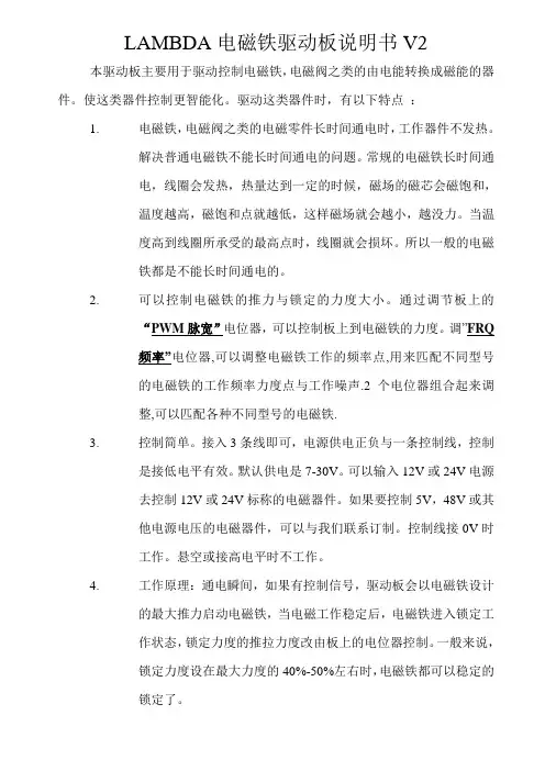
LAMBDA电磁铁驱动板说明书V2 本驱动板主要用于驱动控制电磁铁,电磁阀之类的由电能转换成磁能的器件。
使这类器件控制更智能化。
驱动这类器件时,有以下特点:1.电磁铁,电磁阀之类的电磁零件长时间通电时,工作器件不发热。
解决普通电磁铁不能长时间通电的问题。
常规的电磁铁长时间通电,线圈会发热,热量达到一定的时候,磁场的磁芯会磁饱和,温度越高,磁饱和点就越低,这样磁场就会越小,越没力。
当温度高到线圈所承受的最高点时,线圈就会损坏。
所以一般的电磁铁都是不能长时间通电的。
2.可以控制电磁铁的推力与锁定的力度大小。
通过调节板上的“PWM脉宽”电位器,可以控制板上到电磁铁的力度。
调”FRQ频率”电位器,可以调整电磁铁工作的频率点,用来匹配不同型号的电磁铁的工作频率力度点与工作噪声.2个电位器组合起来调整,可以匹配各种不同型号的电磁铁.3.控制简单。
接入3条线即可,电源供电正负与一条控制线,控制是接低电平有效。
默认供电是7-30V。
可以输入12V或24V电源去控制12V或24V标称的电磁器件。
如果要控制5V,48V或其他电源电压的电磁器件,可以与我们联系订制。
控制线接0V时工作。
悬空或接高电平时不工作。
4.工作原理:通电瞬间,如果有控制信号,驱动板会以电磁铁设计的最大推力启动电磁铁,当电磁工作稳定后,电磁铁进入锁定工作状态,锁定力度的推拉力度改由板上的电位器控制。
一般来说,锁定力度设在最大力度的40%-50%左右时,电磁铁都可以稳定的锁定了。
5.产品的V2版本增加了预留了OCP 过流保护,OTP 过温度保护功能,OCP过流保护是用来预防负载短路保护用的,可以设置电位器调节,过电流保护点.一般来说直接用默认设置即可,不需要调节.关于OTP 过温度保护功能,这个要配合温度电阻NTC10K 型号来使用.边上的2个白色插头是用来插10K NTC 热敏电阻的,这个热敏电阻可以固定到电磁铁上或其它用电的地方,只要这个探测到温度高到设定点,电磁铁就会关闭,该功能是选配的,默认发货是没有的.如果需要,请与客服联系. 产品展示:备注:下图为V1的老款产品,接口控制一样的,老款产品已经停产,新版的产品功能更加强大,性能更加稳定.新款的产品比来款的尺寸宽度要大一倍,长度一样的都是72MM.输出负调节锁定力设正跳针,基本不用调。

Eaton 168805Eaton Moeller® series MSC-DEA DOL starter, 380 V 400 V 415 V: 0.37 kW, 100 kA, Ir: 1 - 4 A, Connection to SmartWire-DT: yes, 24 V DC, DC Voltage, Screw terminalsGeneral specificationsEaton Moeller® series MSC-DEA DOL starter168805128 mm242 mm 45 mm 1.1 kgVDE 0660 IEC/EN 60947-4-1MSC-DEA-4-M17(24VDC)Product NameCatalog Number Product Length/Depth Product Height Product Width Product Weight Certifications Model CodeShort-circuit releaseTemperature compensated overload protection AdjustableScrew terminalsIn conjunction with PKE-SWD-32 SmartWire DT PKE module Yes2700 (Class 10) AC-4 cycle operation, Main conducting paths 500 (Class 5) AC-4 cycle operation, Main conducting paths 900 (Class 15) AC-4 cycle operation, Main conducting paths 1000 (Class 20) AC-4 cycle operation, Main conducting paths For all combinations with an SWD activation, you need not adhere to the minimum current flow times and minimum cut-out periods.Note: Going below the minimum current flow time can cause overheating of the load (motor).≤ 500 ms, main conducting paths, AC-4 cycle operationIP00NEMA OtherDirect starterDIN rail11 A4 AFitted with: Functions ClassConnectionConnection to SmartWire-DTCoordination typeCurrent flow times - minCut-out periods - minDegree of protectionModelMounting methodNumber of auxiliary contacts (normally closed contacts) Number of auxiliary contacts (normally open contacts) Overload release current setting - minOverload release current setting - maxIII3Other bus systems6000 V ACAlso motors with efficiency class IE3 Starter with electronic trip unitDC -25 °C55 °C4 A4 A4 A0.75 kW3.6 kW2.2 kW230 - 415 V AC50 A 100000 A 186 A 0.86 W 0 V0 V0 V0 V24 VOvervoltage categoryPollution degreeProtocolRated impulse withstand voltage (Uimp) Suitable forTypeVoltage type Ambient operating temperature - minAmbient operating temperature - maxRated operational current (Ie)Rated operational current (Ie) at AC-3, 380 V, 400 V, 415 V Rated operational current (Ie) at AC-3, 500 VRated operational power at AC-3, 220/230 V, 50 HzRated operational power at AC-3, 380/400 V, 50 HzRated operational power at AC-3, 500 V, 50 HzRated operational voltageRated conditional short-circuit current (Iq), 500 VRated conditional short-circuit current (Iq), type 2, 380 V, 400 V, 415 VShort-circuit release (Irm) - max Power consumption (sealing) at DCRated control supply voltage (Us) at AC, 50 Hz - min Rated control supply voltage (Us) at AC, 50 Hz - max Rated control supply voltage (Us) at AC, 60 Hz - min Rated control supply voltage (Us) at AC, 60 Hz - max Rated control supply voltage (Us) at DC - minRated control supply voltage (Us) at DC - max24 VEquipment heat dissipation, current-dependent Pvid1.5 WHeat dissipation capacity Pdiss0 WHeat dissipation per pole, current-dependent Pvid0.5 WRated operational current for specified heat dissipation (In)4 AStatic heat dissipation, non-current-dependent Pvs0.86 W10.2.2 Corrosion resistanceMeets the product standard's requirements.10.2.3.1 Verification of thermal stability of enclosuresMeets the product standard's requirements.10.2.3.2 Verification of resistance of insulating materials tonormal heatMeets the product standard's requirements.10.2.3.3 Resist. of insul. mat. to abnormal heat/fire by internalelect. effectsMeets the product standard's requirements.10.2.4 Resistance to ultra-violet (UV) radiationMeets the product standard's requirements.10.2.5 LiftingDoes not apply, since the entire switchgear needs to beevaluated.10.2.6 Mechanical impactDoes not apply, since the entire switchgear needs to beevaluated.10.2.7 InscriptionsMeets the product standard's requirements.10.3 Degree of protection of assembliesDoes not apply, since the entire switchgear needs to beevaluated.10.4 Clearances and creepage distancesMeets the product standard's requirements.10.5 Protection against electric shockDoes not apply, since the entire switchgear needs to beEaton Corporation plc Eaton House30 Pembroke Road Dublin 4, Ireland © 2023 Eaton. Wszelkie prawa zastrze żone.Eaton is a registered trademark.All other trademarks areproperty of their respectiveowners./socialmediaevaluated.Does not apply, since the entire switchgear needs to be evaluated.Is the panel builder's responsibility.Is the panel builder's responsibility.Is the panel builder's responsibility.Is the panel builder's responsibility.Is the panel builder's responsibility.The panel builder is responsible for the temperature rise calculation. Eaton will provide heat dissipation data for the devices.Is the panel builder's responsibility. The specifications for the switchgear must be observed.Is the panel builder's responsibility. The specifications for the switchgear must be observed.The device meets the requirements, provided the information in the instruction leaflet (IL) is observed.Simple, flexible and safe! Distribution system for motor-starter combinations DA-DC-00004109.pdf DA-DC-00004245.pdf eaton-manual-motor-starters-dol-starter-msc-d-dimensions.epseaton-manual-motor-starters-mounting-msc-d-dol-starter-3d-drawing.eps eaton-manual-motor-starters-dol-starter-msc-d-3d-drawing-002.eps DA-CE-ETN.MSC-DEA-4-M17(24VDC)IL03402010Z DA-CS-msc_de_bg2DA-CD-msc_de_bg2eaton-manual-motor-starters-msc-d-dol-starter-wiring-diagram.eps 10.6 Incorporation of switching devices and components 10.7 Internal electrical circuits and connections 10.8 Connections for external conductors 10.9.2 Power-frequency electric strength 10.9.3 Impulse withstand voltage 10.9.4 Testing of enclosures made of insulating material 10.10 Temperature rise10.11 Short-circuit rating10.12 Electromagnetic compatibility10.13 Mechanical functionBroszuryCertyfikatyDWGeCAD modelInstrukcje monta żu mCAD model Schematy po łączeń。
Pressinformation Liebherr opens new logistics centre at Oberopfingen, Germany∙Spare parts supplies for the Earthmoving Equipment division will be managed froma new central location, and other construction machinery divisions are set to follow. ∙Modern technology guarantees reliable supplies for Liebherr customers.∙Ideal connections to transport infrastructure and major Liebherr production facilities.Kirchdorf an der Iller (Germany), 19 June 2015 –Around 1,000 guests attended the opening ceremony of the Liebherr Group's new logistics centre on 19 June 2015 at Oberopfingen, Germany. From the district of Kirchdorf an der Iller, the family-run company will in the future supply customers around the world with spare parts for earthmoving machines.The logistics centre is the new central hub from which Liebherr customers around the world will be supplied with spare parts for wheeled and crawler excavators, wheel loaders, crawler tractors and other earthmoving machines. Until 2013, the management of spare parts supplies was more decentralised. In view of the growing product range and increasingly complex material flows, Liebherr decided to centralise its system, initially organising it from smaller, existing warehouses. In mid-2013, the company finally began to build the new, larger and more modern logistics centre.“Our customer now get their spare parts faster,” explains Martin Barth, managing director of the operating company Liebherr-Logistics GmbH. “This important step guarantees that we will remain competitive in the future.” Around 1,000 guests at the opening ceremony –including the Liebherr family –were given an insight into the technology, proportions and processes. In his address, Dr. Heiko Schmid, district chief executive of the Biberach district, stressed the importance of the Liebherr Group for the region and welcomed the decision to strengthen existing commitments with new logistics centre.Fully automated material flow and maximum supply reliabilityThe new central warehouse has an area of 47,000 m² – about the size of six football pitches – space for about 100,000 different spare parts for the Earthmoving Equipment division. Parts are taken into and out of stock in the automatic warehouse areas - which can be up to 36 m high - by energy-efficient operating machines. The responsible persons at Liebherr-Logistics GmbH employ extremely short throughput times: “Our modern warehouse technology and order picking systems make it possible to ship 1,600 individual orders to many European countries – almost all of them on the day the order is received,” explains Martin Barth. Redundant IT systems, the ability to conduct preventative maintenance work during ongoing operations and modern fire prevention measures guarantee maximum supply reliability.Strategically important location, best transportation connections and future potentialThe location at Oberopfingen was chosen deliberately. Not only is the site directly next to the A7 autobahn, it is also in the immediate neighbourhood of the major production site for Liebherr earthmoving machines at Kirchdorf an der Iller. Other plants from the construction machinery and components divisions in France, Austria and Switzerland are also not far away. “We consi dered, analysed and evaluated various locations for the warehouse,” Martin Barth continues. “In the end, Oberopfingen was the favourite.” In the final expansion phase in a few years time, the site should grow to a total of 360,000 m², or more than 50 football pitches, and hall space will be created to secure the logistics processes for the decades ahead. In the long term, the Liebherr Group is planning to merge the spare parts logistics of other construction machinery divisions in Oberopfingen.Captionsliebherr-logistics-centre-1-300dpi.jpgThe new Liebherr logistics centre at Oberopfingen near Kirchdorf an der Illerliebherr-logistics-centre-2-300dpi.jpgMartin Barth, managing director of Liebherr-Logistics GmbH (right), and logistics manager Kilian Ribheggeliebherr-logistics-centre-3-300dpi.jpgManual warehouse area and shipping at the new Liebherr logistics centre at Oberopfingenliebherr-logistics-centre-4-300dpi.jpgSpare parts are automatically moved on roller conveyors.Contact personKristian KüppersCorporate CommunicationPhone: +49 7351 41-2708E-mail:******************************Published byLiebherr-International Deutschland GmbHBiberach / Riss, Germany。
推拉电磁铁的行程
推拉电磁铁的行程
一、推拉电磁铁分类:
从产品结构上分,分为框架推拉电磁铁,圆管推拉电磁铁。
框架推拉电磁铁主要是外壳由U形或C形,O形的导磁铁板冲压或加工而成,页圆管推拉电磁铁,则是由管形导磁铁材料加工成的外壳。
不管是哪种推拉电磁铁,从原理来讲,都是一样,而且其体积大小和行程力量的关系也都相近。
二、推拉电磁铁行程:
行程:前面有讲到过,行程是指:电磁铁通电,可动滑杆从起点运动到终点的距离,我们称之为行程。
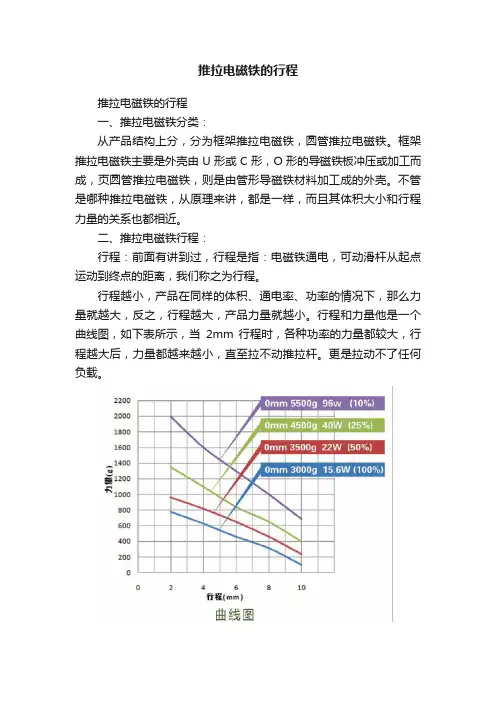
行程越小,产品在同样的体积、通电率、功率的情况下,那么力量就越大,反之,行程越大,产品力量就越小。
行程和力量他是一个曲线图,如下表所示,当2mm 行程时,各种功率的力量都较大,行程越大后,力量都越来越小,直至拉不动推拉杆。
更是拉动不了任何负载。
三、行程最大和行程最小:
现有市场中,行程最小的推拉电磁铁0.5mm,
行程最大的推拉电磁铁,那这个数就没有准了,其实再大都可定制,只是代价问题,我司做过最大行程为500mm。
为定制产品。
四、行程大小和体积的关系,一般其况下,我司自凭经验认为,一般行程大小在电磁
铁主体长度的30%以内,如主体长40mm的电磁铁,行程一般不好超过13mm,超过就没力量了。
以上为做电磁铁十五年的经验之谈,没有一定的科学依据,只是供大家型参考及同行探讨。
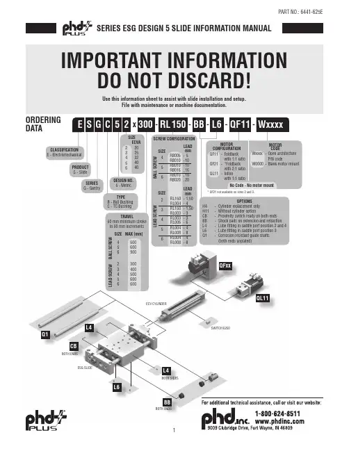
No Code -No motor mountRL 300x -WxxxxQF 511150--SIZE 20253250 mm minimum stroke in 50 mm increments TRAVEL DESIGN NO.5 - MetricSCREW CONFIGURA B A L L S C R E WTIONSIZE 456mm------L E A D S C R E WB A L L SC R E WL E A D S C R E WSIZE 234LEADLEAD mm1.5041.50336RL150 -RL004 -RL150 -RL003 -RL003 -RL006 -564848RL004 -RL008 -RL004 -RL008 -E S PRODUCT S - SlideSERIES G - GantryCLASSIFICATION E - ElectromechanicalG C 2BB TYPE B - Ball Bushing C - TC Bushing 234404056MAX [mm]500600600SIZE 44003300500600900256456-L6-MOTOR CONFIGURATION QF11-Foldbackwith 1:1 ratioQF21-*Foldbackwith 2:1 ratioQL11-Inlinewith 1:1 ratioMOTOR CODEWxxxx -Open architectureP/N codeW0000-Blank motor mountECVA * QF21 not available on sizes 2 and 3.RB005 RB010 RB010 RB016 RB010 RB020 51010161020OPTIONS H4-Cylinder replacement only H11-Without cylinder option CB -Proximity switch ready on both ends BB -Shock pads on extension and retraction L4-Lube fitting in saddle port position 2 and 4L6-Lube fitting in saddle port position 3Q1-Corrosion resistant guide shafts (both ends unplated)BOTH ENDSBOTH ENDSBBQFxxQL11Q1CBL6BOTH SIDESL4L4ORDERING DATAUse this information sheet to assist with slide installation and setup. File with maintenance or machine documentation.IMPORTANT INFORMATIONDO NOT DISCARD!SERIES ESG DESIGN 5 SLIDE INFORMATION MANUALSPECIFICATIONSBALL SCREW SERIES ESG REPEATABILITY1±0.010 mm [±0.0004 in]MAXIMUM BACKLASH 20.18 mm [0.007 in]RATED LIFERefer to Life vs. Thrust Chart FULL TRAVEL TOLERANCE 7+3.5/-0.0 mm [+0.138/-0.000 in]DUTY CYCLE100%OPERATING TEMPERATURE 4 - 65°C [40 - 150°F]LUBRICATION INTERVAL 3Horizontal: 2500 km [100 million in], Vertical: 1500 km [60 million in]SPECIFICATIONSSIZE 456M E C H A N I C SMAXIMUM TRAVELmm [in]500 [19.69]600 [23.62]900 [35.43]DRIVE MECHANISM Ball ScrewSCREW DIAMETERmm 121616SCREW CONFIGURATION -RB005-RB010-RB010-RB016-RB010-RB016SCREW LEADmm/rev 51010161016GUIDE SHAFT DIAMETER mm162025GUIDE SHAFT BEARING TYPE Ball BushingS P E E D 4MAXIMUM SPEED mm/sec [in/sec]500 [19.6]1000 [39.3]1000 [39.3]1600 [63.0]1000 [39.3]1600 [63.0]MAXIMUM RPMrev/min 6000MAXIMUMACCELERATION -QL11mm/sec 2[in/sec 2]19.6 [772]-QFx1mm/sec 2 [in/sec 2]9.8 [386]T H R U S T 4MAXIMUM THRUST N [lbf]1360 [306]680 [153]2430 [546]1520 [342]2430 [546]1520 [342]NOMINAL THRUST 5N [lbf]400 [90]330 [74]1270 [285]975 [219]1270 [285]975 [219]T O R Q U E PERMISSIBLE DRIVE TORQUE 6-QL11Nm [in-lb] 1.2 [10.62] 4.3 [38.06] 4.3 [38.06]-QFx1Nm [in-lb]0.84 [7.43] 3 [26.55] 3 [26.55]NO-LOAD TORQUENm [in-lb]0.15 [1.33]0.40 [3.54]0.60 [5.31]W E I G H TTOTAL @ ZERO STROKE (W OT )kg [lb] 6.21 [13.7]8.56 [18.87]11.19 [24.67]TOTAL LENGTH ADDER (W LT )kg/mm [lb/in]0.010 [0.57]0.132 [0.74]0.0169 [0.92]MOVING @ ZERO STROKE (W OM )kg [lb] 2.45 [5.41] 3.84 [8.47] 4.89 [10.67]MOVING LENGTH ADDER (W LM )kg/mm [lb/in]0.0006 [0.038]0.0010 [0.058]0.0010 [0.058]I N E R T I AACTUATOR @ ZERO STROKE (J O )kg-m 2 [lb-in 2] 3.00 x 10⁻⁶[0.010] 1.50 x 10⁻⁵ [0.051] 1.50 x 10⁻⁵ [0.051]LENGTH ADDER (J L )kg-m 2/mm [lb-in 2/in]9.85 x 10-9 [0.0009] 2.90 x 10⁻⁸ [0.0025]2.90 x 10⁻⁸ [0.0025]MOVING WEIGHT ADDER (J M )kg-m 2/kg [lb-in 2/lb] 6.21 x 10-72.48 x 10-6 2.48 x 10⁻⁶ 6.36 x 10⁻⁶ 2.48 x 10⁻⁶ 6.36 x 10⁻⁶[9.63 x 10⁻⁴][3.85 x 10⁻³][3.85 x 10⁻³][9.86 x 10⁻³][3.85 x 10⁻³][9.86 x 10⁻³]MOTORCONFIGURATION (J Q )-QF11kg-m 2 [lb-in 2] 1.40 x 10⁻⁵ [0.048] 4.71 x 10⁻⁵ [0.161]4.71 x 10⁻⁵ [0.161]-QF21 2.75 x 10⁻⁵ [0.094]8.28 x 10⁻⁵ [0.283]8.28 x 10⁻⁵ [0.283]-QL113.14 x 10-6 [0.011] 6.11 x 10⁻⁶ [0.021]6.11 x 10⁻⁶ [0.021]NOTES:1) UNIDIRECTIONAL2) AXIAL FREE PLAY WHEN DRIVE SHAFT LOCKED3) REFER TO OPERATING INSTRUCTIONS FOR RE-LUBRICATION DETAILS 4) REFER TO PERFORMANCE CHARTS IN CATALOG 5) 2500 km [100 MILLION in] LIFE6) CORRESPONDS TO MAXIMUM THRUST7) FOR HOMING AND INCREASED APPLICATION FLEXIBILITY, INCLUDE EXTRA TRAVEL WHEN NECESSARY 8) ALL DIMENSIONS ARE FOR REFERENCE ONLY UNLESS SPECIFICALLY TOLERANCED. REFER TO ONLINE SIZING SOFTWARE FOR ACTUAL VALUES.SPECIFICATIONSLEAD SCREW SERIES ESG REPEATABILITY 1±0.5 mm [±0.020 in] (Typical)MAXIMUM BACKLASH 20.20 mm [0.008 in]RATED LIFERefer to Online SizingFULL TRAVEL TOLERANCE +3.5/-0.0 mm [+0.138/-0.000 in]MAXIMUM DUTY CYCLE 35%OPERATING TEMPERATURE 4 - 65°C [40 - 150°F]LUBRICATION INTERVAL 3Horizontal: 500 km [20 million in], Vertical: 250 km [10 million in]SPECIFICATIONSSIZE23456M E C H A N I C SMAXIMUM TRAVEL mm [in]300 [11.811]400 [15.70]500 [19.69]600 [23.62]600 [23.62]SCREW DIAMETER mm810121616SCREW CONFIGURATION -RL150-RL004-RL150-RL003-RL003-RL006-RL004-RL008-RL004-RL008SCREW LEADmm/rev 1.541.53364848GUIDE SHAFT DIAMETER mm10 [0.394]12 [0.472]16 [0.630]20 [0.787]25 [0.984]GUIDE SHAFT BEARING TYPE Composite Bushing S P E E D 4MAXIMUM SPEED mm/sec [in/sec]30 [1.2]80 [3.15]30 [1.20]60 [2.40]60 [2.40]120 [4.80]80 [3.15]160 [6.30]80 [3.15]160 [6.30]MAXIMUM RPMrev/min1200MAXIMUM ACCELERATION m/sec 2[in/sec 2]0.3 [11.81]1.0 [39.37]0.3 [11.81] 1.0 [39.37]0.3 [11.81] 1.0 [39.37]0.5 [19.69] 1.0 [39.37]0.5 [19.69] 1.0 [39.37]T H R U S T 4MAXIMUM THRUST N [lbf]300 [67.5]150 [33.7]500 [112]250 [56]800 [180]400 [90]1600 [360]800 [180]1600 [360]800 [180]T O R Q U EPERMISSIBLE DRIVE TORQUE 5-QL11Nm [in-lb]0.5 [4.42]0.7 [6.20] 1.2 [10.62] 4.3 [38.06] 4.3 [38.06]-QFx1Nm [in-lb]0.84 [7.43] 3 [26.55] 3 [26.55]NO-LOAD TORQUENm [in-lb]0.09 [0.80]0.12 [1.00]0.15 [1.33]0.40 [3.54]0.60 [5.31]W E I G H TTOTAL @ ZERO STROKE (W OT )kg [lb] 2.57 [5.66] 3.37 [7.42] 6.13 [13.54]8.45 [18.63]11.08 [24.43]TOTAL LENGTH ADDER (W LT )kg/mm [lb/in]0.003 [0.14]0.004 [0.21]0.010 [0.57]0.0132 [0.74]0.017 [0.92]MOVING @ ZERO STROKE (W OM )kg [lb] 1.07 [2.35] 1.50 [3.31] 2.38 [5.25] 3.73 [8.23] 4.735 [10.43]MOVING LENGTH ADDER (W LM )kg/mm [lb/in]0.0004 [0.021]0.0007 [0.038]0.0007 [0.038]0.0010 [0.058]0.0010 [0.058]I N E R T I AACTUATOR @ ZERO STROKE (J O )kg-m 2[lb-in 2]1.66 x 10⁻⁶[0.006]2.09 x 10⁻⁶[0.007]3.00 x 10⁻⁶[0.010]1.50 x 10⁻⁵[0.051]1.50 x 10⁻⁵ [0.051]LENGTH ADDER (J L ) kg-m 2/mm [lb-in 2/in] 1.59 x 10⁻⁹ [0.00014]4.94 x 10⁻⁹ [0.00043]9.85 x 10⁻⁹ [0.0009] 2.90 x 10⁻⁸ [0.0025] 2.90 x 10⁻⁸ [0.0025]MOVING WEIGHT ADDER (J M )kg-m 2/kg [lb-in 2/lb] 3.8 x 10-81.01 x 10-7 3.8 x 10-87.6 x 10-87.6 x 10⁻⁸ 1.52 x 10⁻⁷ 1.01 x 10-72.03 x 10-7 1.01 x 10⁻⁷ 2.03 x 10⁻⁷[5.89 x 10⁻⁵][1.57 x 10⁻⁴][5.89 x 10⁻⁵][1.18 x 10⁻⁴][1.18 x 10⁻⁴][2.36 x 10⁻⁴][1.57 x 10⁻⁴][3.14 x 10⁻⁴][1.57 x 10⁻⁴][3.14 x 10⁻⁴]MOTORCONFIGURATION (J Q )-QF11kg-m 2 [lb-in 2]2.69 x 10⁻⁵ [0.092] 2.69 x 10⁻⁵ [0.092] 1.40 x 10⁻⁵ [0.048] 4.71 x 10⁻⁵ [0.161] 4.71 x 10⁻⁵ [0.161]-QF21––2.75 x 10⁻⁵ [0.094]8.28 x 10⁻⁵ [0.283]8.28 x 10⁻⁵ [0.283]-QL111.89 x 10-6 [0.006]1.89 x 10⁻⁶ [0.006]3.14 x 10⁻⁶ [0.011]6.11 x 10⁻⁶ [0.021]6.11 x 10⁻⁶ [0.021]NOTES:1) UNIDIRECTIONAL2) VALUES CORRESPOND TO INITIAL (AS SUPPLIED/NEW) CONDITION. DUE TO FRICTIONAL WEAR BACKLASH MAY INCREASE OVER TIME.3) REFER TO OPERATING INSTRUCTIONS FOR RE-LUBRICATION DETAILS 4) REFER TO PERFORMANCE CHARTS IN CATALOG 5) CORRESPONDS TO MAXIMUM THRUSTMOUNTING INFORMATION: SERIES ESG SLIDESSTART-UP PROCEDURE• The ESG Slide should be securely mounted before powering up the electric motor.• Care should be taken to provide adequate space for the slide tool plate to extend.• Make sure that the electric motor and the motor mount kit (inline or fold-back) are securely mounted to the cylinder and fastened with the recommended tightening torques.• The cylinder rod of the ECV is a non-rotating element. When tightening or loosening the threaded joint, use the flats on the rod end to prevent torque transmission into the rod.• DO NOT use the slide in shock or impact load applications (Example: End of travel impact against a fixed stop).• The slide comes with a self aligning rod coupler between the cylinder rod and saddle. This rod coupler prevents internal friction caused by misalignment, provides greater reliability by reducing component wear and simplifying alignment problems.• The maximum input torque and speed should not exceed the values specified in the engineering data on pages 2 and 3.• The slide is designed for use in a clean industrial environment and designed to prevent solid particles from entering the slide.• Do not use the slide in a wash-down environment. Please consult PHD if your application requires wash-down.• The ESG Slide is not field repairable.• After each lubrication interval, inspect shaft couplings, timing belt and screw assembly for excessive backlash. Replace coupling spider or timing belt as necessary.Re-lubricate nut and screw using recommended grease at the following intervalsScrew Type LubricantOrientationHorizontal Vertical -RBxxx (Ball Screw)Castrol Longtime PD2 (NLGI Class 2)100 M in [2500 km]60 M in [1500 km]-RLxxx (Lead Screw)NYE Rheolube 368 AX-120 M in [500 km]10 M in [250 km]PART NO.: 6441-625ESPACE BETWEEN PISTON AND NUTFIGURE CFigure A2RECOMMENDED GREASE: CASTROL LONGTIME PD 2 (NLGI CLASS2)1. Remove the SLOT COVER or LUBE PLUG from the cylinder (Figure A1).• ROTATING (ECVR) UNITS: Fully retract the cylinder and rotate rod clockwise until the LUBE PORT in the piston is accessible. This step may require disengagement of the motor brake or attached load.2. Using grease gun, pump the recommended grease into the LUBE PORT in the BALL NUT (Figure B). Be sure to lubricate the indicated LUBE PORT in the BALL NUT, not extraneous geometry in piston (Figure C).3. Pump the grease until it fully fills the piston assembly.4. Cycle the cylinder at low speeds or by hand keeping any contaminant from entering the tube, then repeat step 3.5. Reinstall the SLOT COVER or LUBE PLUG.RECOMMENDED GREASE: NYE RHEOLUBE 368 AX-11. Remove the SLOT COVER or the LUBE PLUG from the cylinder (Figure A1).• NON-ROTATING (ECVA) UNITS: Fully retract the cylinder and remove the CAP END FHCS in the anti-rotation key. (FIGURE A1)2. ROTATING (ECVR) UNITS: Fully retract the cylinder and rotate the rod clockwise until the LUBE PORT in piston is accessible. (FIGURE A2) Thisstep may require disengagement of the motor brake or attached load.3. Using grease gun, pump the recommended grease into LUBE PORT in the PISTON (Figure A2). Be sure to lubricate the indicated LUBE PORT inthe PISTON.4. Pump the grease until it fully fills the piston assembly.5. For Lead Screw units with 200 mm of travel or more, fully extend the cylinder and lube the screw as shown in (FIGURE B2).6. Cycle the cylinder at low speeds or by hand keeping any contaminant from entering the tube, then repeat step 3.7. Reinstall the SLOT COVER or LUBE PLUG.MAINTENANCE & OPTIONS: SERIES ESG SLIDESSHOCK PADS BOTH DIRECTIONSThis option provides urethane shock pads on retraction and extension for crash protection, eliminating metal-to-metal contact as the saddle reaches physical end of travel. This -BB option does not affect the overall slide length.CYLINDER REPLACEMENT ONLY (WITHOUT SLIDE)H11SLIDE REPLACEMENT ONLY (WITHOUT CYLINDER)500x -511010--4--This option provides complete cylinder replacement motormounting and is included/excluded based on ordering specifications. If motor mounting is desired, full unit description is required.This option provides the slide mechanism only without cylinder or motor mounting. Included with option -H11 is all the hardware required for mounting standard PHD Series ECV Cylinders or pneumatic standard VDMA/ISO cylinders to the slide. A self-aligning rod coupling is also provided, making it easy to attach the appropriate VDMA/ISO cylinder. (No extra rod extension required.)11--NOTES:1) LOCK SCREW TORQUE IS 30 in-lb [3.39 Nm].SIZE B C 2 5.5173 5.59439539639PART NO.: 6441-625EMOTOR CODEYour Motor, Your Way customizable motor mounting is generated by PHD’s extensive motor database at www.config.. The user may select their compatible motor of choice from the pre-populated motor database. In the event the chosen motor is not in the database, they may enter necessary motor features to generate the PHD motor code.The tailored motor mounting components are included with the specified driver and shipped in kit form.Extremely hard corrosion-resistant coating on the guide shafts for use in applications where moisture may corrode untreated hardened and ground shafts. End faces of the shafts remain uncoated. Consult PHD for fully coated shafts.LUBE FITTING IN SADDLE PORT POSITION 2 AND 4Lube fittings provide an easy efficient method for lubricating the bearings and shafts for extended life beyond the normal catalog specifications. Periodic lubrication (every 25 million inches of travel [635 km]) is recommended for applications where heat, dust, orother conditions will dry out the bearings and shafts. PHD suggests a lightweight oil.NOTE: *SEE CATALOG DIMENSIONSLUBE FITTING IN SADDLE PORT POSITION 3CORROSION RESISTANTGUIDE SHAFTSPROXIMITY SWITCH READY BOTH ENDSThis option provides targets in the slide saddle for use with 8 mm inductive proximity switches. The end plates of the slide come standard with provisions for mounting the 8 mm proximity switches on both ends. Proximity switches must be ordered separately.SIZEA B C D 220.53427.57.5314.528329414.52837.59514.528438614.528518ASSEMBLY INSTRUCTIONS(Please use Loctite 248 or equivalent on all fasteners)1.Mount the coupling hub half 5 on the ECV cylinder shaft. Dimensions in Figures D & E are factory suggestions and may not work in every combination. Ensure maximum coupling engagement on each shaft while retaining full spider engagement. Avoid axial loading either shaft.2.Mount the spider 7 to the coupling hub 5.(continued on next page)Figure D Figure E DESCRIPTIONQTY TORQUE in-lb [Nm]SIZE 2SIZE 3SIZE 4SIZE 5SIZE 61Coupling Housing 1----------2Motor Mounting Plate1----------3Brite Zinc Plate Metric Fasteners 426[2.9]26[2.9]50[5.5]50[5.5]50[5.5]4Brite Zinc Plate Metric Fasteners 426[2.9]26[2.9]100[11]100[11]100[11]5Coupling Hub 16[0.72]6[0.72]18[2]18[2]18[2]6Coupling Hub 16[0.72]6[0.72]18[2]18[2]18[2]7Coupling Spider 1----------8Hole Plug 2----------9Motor Screw4See note belowNOTE: The torque on these screws will depend on the screw sizes on your motor.Standard Assembly ESG Size Dimension L in [mm]20.118[3]30.118[3]40.197[5]50.295[7.5]60.295[7.5]Assembly with “F” Type Mount ESG Size Dimension M in [mm]20.197[5]30.197[5]40.276[7]50.374[9.5]60.374[9.5]INLINE MOTOR MOUNTING WITH 1:1 DRIVE RATIO3. Mount the other coupling hub 6 on the spider 7. Loosen the cap screw on coupling hub 6.4. Using the four cap screws 4, fasten the housing 1 to the cylinder. If an “F” type foot mounting bracket option is being used, mount thebracket between the cylinder and the housing 1 as shown in Figure E. Align the cap screw on coupling hub 6 with the hole in the housing 1.5. Mount the motor mounting plate 2 to the housing using the four fasteners 3, and tighten to the recommended torque.6. Insert the motor carefully through the motor mounting plate 2 such that the motor shaft enters the hole in the coupling hub 6. You may haveto apply some force to fully insert the motor shaft in the coupling hub.7. With the motor flush to the motor mounting plate, use the mounting screws 9 to fasten the motor to the mounting plate 2.8. To tighten the cap screw on coupling hub 6, align the head of the cap screw with the hole in the housing 1 as shown in Figure F. If you havelost alignment, realign by either pushing or pulling the cylinder rod or by rotating the motor shaft. Tighten to the recommended torque.9. Plug the two holes on the coupling housing using the plastic plugs 8.Figure F(continued on next page)FOLDBACK MOTOR MOUNTING WITH 1:1 DRIVE RATIO FOLDBACK MOTOR MOUNTING WITH 2:1 DRIVE RATIODESCRIPTIONQTY TORQUE in-lb [Nm]ECV20ECV25ECV32ECV40ECV501Motor Mounting Plate 1----------2Drive Cover1----------3Brite Zinc Metric Fasteners 460[7]60[7]60[7]100[11]100[11]4Brite Zinc DIN 7984 Metric Fastener 4100[11]100[11]100[11]100[11]230[26]5Metric Dowel Pin 2----------6Pulley 1----------7Pulley 1----------8Timing Belt1----------9Metric Socket Set Screw 1----15[1.5]27[3]27[3]10Metric Socket Set Screw 1----See note 1 below11Motor Screw 4----12Motor Adaptor Pulley 1See note 4-13Cylinder Adaptor Pulley144[5]44[5]-NOTE:1) The torque on these screws will depend on the screw sizes on your motor.2) The key shown with the cylinder side pulley will be factory fitted on the cylinder shaft.3) The key shown with the motor side pulley to be used from the customer’s motor.4) The torque on this adaptor will depend on the shaft size of the motor. Ø 5 mm shaft = 44 [5]Ø 6 mm to Ø 6.35 mm shaft = 70 [8] Ø 8 mm shaft = 130 [15]ASSEMBLY INSTRUCTIONSUse Loctite 248 or equivalent on all fasteners (excluding Pulley Adapters).Torque to recommended values.1. Attach Motor Mounting Plate 7 to actuator and secure with supplied Fasteners 4.2. Mount motor [not shown] to Motor plate using supplied Fasteners 11.3. Attach Pulleys 6 and 7 to motor and actuator shafts.SIZES 2 & 3a. Insert Pulley Adapter 12 into Pulley 7 and slide over motor shaft.b. Maintain clearance between Pulley 7 and Motor Mounting Plate 1 as shown in fig H .c. Torque Pulley Adapter 7 to recommended value. Ensure pulley is protected while torqueing.d. Place Timing Belt 8 around Pulley 6.e. Insert Pulley Adapter 13 into Pulley 6.f. Slide Pulley Adapter 13 on actuator shaft while also sliding Timing Belt 8 around Pulley 7 as shown in figure I . Maintain clearance between Pulley 6 and Motor Mounting Plate 1 as shown figure H .g. Torque Pulley Adapter 7 to recommended value.ESG Size Dimension N in [mm]20.041[1.0]30.053[1.3]40.067[1.7]50.047[1.2]60.047[1.2]ASSEMBLY INSTRUCTIONSSIZES 4 - 6a. Slide Pulley 7 over motor shaft while insuring proper placement of key in keyway or Set Screw(s) 10 over flat(s)on motor shaft.b. Maintain clearance between Pulley 7 and Motor Mounting Plate 1 as shown in fig H.c. Torque Set Screw(s) 10 to recommended value. There may be multiple Set Screws 10 in Pulley 7.d. Rotate the actuator shaft so the key faces Pulley 7.e. Place Timing Belt 8 around Pulley 6.f. Slide Pulley 6 over actuator shaft while also sliding Timing Belt 8 around Pulley 7 as shown in figure I. Ensure properplacement of key in keyway.g. H. The hub on Pulley 7 should contact theh.4. Verify Pulley 65. Assemble Dowel Pins6. Place Drive Cover 2NOTE: Drive Cover 2。
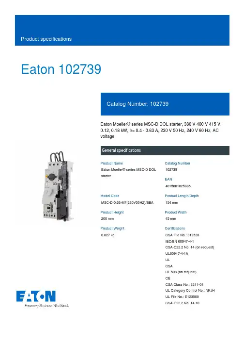
Eaton 102739Eaton Moeller® series MSC-D DOL starter, 380 V 400 V 415 V: 0.12, 0.18 kW, Ir= 0.4 - 0.63 A, 230 V 50 Hz, 240 V 60 Hz, AC voltageGeneral specificationsEaton Moeller® series MSC-D DOL starter1027394015081025886MSC-D-0,63-M7(230V50HZ)/BBA 154 mm 200 mm 45 mm 0.827 kgCSA File No.: 012528 IEC/EN 60947-4-1CSA-C22.2 No. 14 (on request) UL60947-4-1A UL CSAUL 508 (on request) CECSA Class No.: 3211-04 UL Category Control No.: NKJH UL File No.: E123500 CSA-C22.2 No. 14-10Product NameCatalog Number EANModel CodeProduct Length/Depth Product Height Product Width Product Weight CertificationsShort-circuit releaseTemperature compensated overload protection CLASS 10 AScrew terminalsNo2IP20NEMA OtherDirect starterMounting on Busbar 60 mm10.4 A0.63 AIII36000 V ACAlso motors with efficiency class IE3 Starter with Bi-Metal releaseACFitted with: Functions ClassConnectionConnection to SmartWire-DTCoordination typeDegree of protectionModelMounting methodNumber of auxiliary contacts (normally closed contacts) Number of auxiliary contacts (normally open contacts) Overload release current setting - minOverload release current setting - maxOvervoltage categoryPollution degreeRated impulse withstand voltage (Uimp)Suitable forTypeVoltage typeMax. 2000 m -25 °C55 °C 0.6 A0.63 A0.09 kW0.18 kW230 - 415 V AC15 A, 600 V AC, (UL/CSA)1 A, 250 V DC, (UL/CSA)P300, DC operated (UL/CSA) A600, AC operated (UL/CSA)50000 A 9.8 A 1.2 W, Dual-frequency coil in a cold state and 1.0 x Us, at 50 Hz 230 V230 V0 V0 V0 V0 VAltitudeAmbient operating temperature - min Ambient operating temperature - max Rated operational current (Ie)Rated operational current (Ie) at AC-3, 380 V, 400 V, 415 V Rated operational power at AC-3, 220/230 V, 50 HzRated operational power at AC-3, 380/400 V, 50 HzRated operational voltageSwitching capacity (auxiliary contacts, general use) Switching capacity (auxiliary contacts, pilot duty)Rated conditional short-circuit current (Iq), type 2, 380 V, 400 V, 415 VShort-circuit release (Irm) - max Power consumption, sealing, 50 HzRated control supply voltage (Us) at AC, 50 Hz - min Rated control supply voltage (Us) at AC, 50 Hz - max Rated control supply voltage (Us) at AC, 60 Hz - min Rated control supply voltage (Us) at AC, 60 Hz - max Rated control supply voltage (Us) at DC - minRated control supply voltage (Us) at DC - max5.7 W0 W1.9 W0.63 A1.4 WMeets the product standard's requirements.Meets the product standard's requirements.Meets the product standard's requirements.Meets the product standard's requirements.Meets the product standard's requirements.Does not apply, since the entire switchgear needs to be evaluated.Does not apply, since the entire switchgear needs to be evaluated.Meets the product standard's requirements.Does not apply, since the entire switchgear needs to be evaluated.Meets the product standard's requirements.Does not apply, since the entire switchgear needs to be evaluated.Motor Starters in System xStart - brochureSave time and space thanks to the new link module PKZM0-XDM32ME Simple, flexible and safe! Distribution system for motor-starter combinationsProduct Range Catalog Switching and protecting motorsDA-DC-00004910.pdfDA-DC-00004878.pdfeaton-manual-motor-starters-adapter-msc-d-dol-starter-dimensions.eps eaton-general-ie-ready-dilm-contactor-standards.epsDA-CE-ETN.MSC-D-0,63-M7(230V50HZ)_BBAIL03402015ZIL034014ZUIL034038ZUWIN-WIN with push-in technologyDA-CS-msc_d_bba_bg1DA-CD-msc_d_bba_bg1eaton-manual-motor-starters-device-msc-d-dol-starter-wiring-diagram.epsEquipment heat dissipation, current-dependent PvidHeat dissipation capacity PdissHeat dissipation per pole, current-dependent PvidRated operational current for specified heat dissipation (In) Static heat dissipation, non-current-dependent Pvs10.2.2 Corrosion resistance10.2.3.1 Verification of thermal stability of enclosures10.2.3.2 Verification of resistance of insulating materials to normal heat10.2.3.3 Resist. of insul. mat. to abnormal heat/fire by internal elect. effects10.2.4 Resistance to ultra-violet (UV) radiation10.2.5 Lifting10.2.6 Mechanical impact10.2.7 Inscriptions10.3 Degree of protection of assemblies10.4 Clearances and creepage distances10.5 Protection against electric shock10.6 Incorporation of switching devices and components BrochuresCatalogsDeclarations of conformity DrawingseCAD modelInstallation instructionsInstallation videosmCAD modelWiring diagramsEaton Corporation plc Eaton House30 Pembroke Road Dublin 4, Ireland © 2023 Eaton. All Rights Reserved. Eaton is a registered trademark.All other trademarks areproperty of their respectiveowners./socialmediaDoes not apply, since the entire switchgear needs to be evaluated.Is the panel builder's responsibility.Is the panel builder's responsibility.Is the panel builder's responsibility.Is the panel builder's responsibility.Is the panel builder's responsibility.The panel builder is responsible for the temperature rise calculation. Eaton will provide heat dissipation data for the devices.Is the panel builder's responsibility. The specifications for the switchgear must be observed.Is the panel builder's responsibility. The specifications for the switchgear must be observed.The device meets the requirements, provided the information in the instruction leaflet (IL) is observed.10.7 Internal electrical circuits and connections 10.8 Connections for external conductors 10.9.2 Power-frequency electric strength 10.9.3 Impulse withstand voltage 10.9.4 Testing of enclosures made of insulating material 10.10 Temperature rise10.11 Short-circuit rating10.12 Electromagnetic compatibility10.13 Mechanical function。


DIN EN 61508VALVES213213213V24153V-24153VSymbolValve model *1)Port sizeFunctionActuation/ReturnOperating pressure (bar)Flow (l/min)Test certificateIEC 61508 *2)9713535*G 1/43/2Solenoid/Spring 2.5 ... 81300x 9713545* 1/4 NPT 3/2Solenoid/Spring 2.5 (81300x)9713555* G 1/23/2Solenoid/Spring 2.5 ... 826009713565*1/2 NPT 3/2Solenoid/Spring 2.5 ... 826009710535* G 1/45/2Solenoid/Spring 2.5 ... 81300x 9710545* 1/4 NPT 5/2Solenoid/Spring 2.5 (81300x)9710555* G 1/25/2Solenoid/Spring 2.5 ... 826009710565*1/2 NPT 5/2Solenoid/Spring 2.5 ... 826009711535* G 1/45/2Solenoid/Solenoid 2.5 ... 813009711545* 1/4 NPT 5/2Solenoid/Solenoid 2.5 ... 813009712535* G 1/45/3Solenoid/Solenoid, APB 2.5 ... 89509712545*1/4 NPT5/3Solenoid/Solenoid, APB2.5 (8)950SymbolValve model *1)Port sizeFunctionActuation/ReturnOperating pressure (bar)Flow (l/min)Testcertificate IEC 61508 *2)9713735*G 1/43/2Solenoid/Spring 2.5 ... 81300x 9713745* 1/4 NPT 3/2Solenoid/Spring 2.5 (81300x)9713755* G 1/23/2Solenoid/Spring 2.5 ... 826009713765*1/2 NPT 3/2Solenoid/Spring 2.5 ... 826009710735* G 1/45/2Solenoid/Spring 2.5 ... 81300x 9710745* 1/4 NPT 5/2Solenoid/Spring 2.5 (81300x)9710755* G 1/25/2Solenoid/Spring 2.5 ... 826009710765*1/2 NPT 5/2Solenoid/Spring 2.5 ... 826009711735* G 1/45/2Solenoid/Solenoid 2.5 ... 813009711745*1/4 NPT5/2Solenoid/Solenoid2.5 (8)1300*2) S ince May 2008, Date code A8192*3) F or operation in plants according to IEC 61511/61508 -40 ... +40°C see test certificate (on request)Housing: Aluminum anodized: SNBR -40...+65C *3)Housing: Stainless steel: SNBR -40...+65C *3)213213213V24153V-24153V 42513V-53A-EMH 42513*1) Order example: To order a series 97105 Inline valve, aluminum, G ¼” port with a 24 Vdc, IP65, DIN Form A coil, Model Number: 9713535076302400.Valve model code 9713535 + Coil code 076302400 = Model Number: 971353576302400.To order the valve only, replace the * after the Valve model code from the table with 9 zero’s, i.e. 9713535000000000.*1) Order example: To order a series 97105 Inline valve, stainless steel, G ¼” port with a 24 Vdc, IP65, DIN Form A coil, Model Number: 9713735076302400.Valve model code 9713735 + Coil code 076302400 = Model Number: 9713735076302400.To order the valve only, replace the * after the Valve model code from the table with 9 zero’s, i.e. 9713735000000000.0570275000000000VALVES2.170.221.655.79~7.951.2211.263.392.281.261.4225134322.91AA1.261.850.080.141.343122.174.942.42923.740.141.341.26 1.650.06~7.031.421.422.300.980.22231AA2321.181.421.341.202.092.170.221.183.230.941.590.140.061~ 6.46~ 4.2931AA0.062345131.100.942.760.0411.420.222.170.941.181.615.08~7.242.480.872AA0.871.26Valves2 External pilot pressure connection G1/8, 1/8 NPT3 Working port G1/4, G1/2 or 1/4 NPT, 1/2 NPT 9Position of gasket internal pilot air10 Position of gasket external pilot airA - A9101234VALVES2 External pilot pressure connection G1/8, 1/8 NPT 3Working port G1/4, G1/2 or 1/4 NPT, 1/2 NPT 9Position of gasket internal pilot air10 Position of gasket external pilot airA - A 910B - B109A - A910 B - B10951141231.264.374.765.20~9.533.392.760.940.040.870.470.941.472.171.180.220.4723AABB0.8755.084.090.76110.040.945.91~10.240.470.941.425,541232.171.1823AABB0.470.870.871.2656VALVES1.601.061.341.691.932.110.671.693.41M16 x 1.51.100.4712.154.212.541.651.061.602510± 0,2Solenoid operators 1 Connector 4 x 90° rotateable 2 Ø 13 (with spacer tube) 3 M20 x 1.5 or 1/2 - 14 NPT 2.322.780.792.091.632.201.691.14 4.802341.592.483.311.321.691.020.081/2 - 14 NPT21.611.303.253.500.772.502.872.154.212.543.601.65M 20 x 1.51.061.600.4± 0.0082~3567178VALVESManual overrideModel: 0553886 (without detent)Model: 0553887 (with detent)14M 10 x 0,5~1114M 10 x 0,5~11Circuit diagrams AB C ø D ModelM20 x 1.5936 5 to 8220588819000000000M20 x 1.56,527.59 to 13220589385000000000M20 x 1.5143910 to 142405888510000000001/2-14 NPT 15587.5 to 11.9240588925000000000M20 x 1.514397 to 12240589395000000000M20 x 1.5103410 to 14240589387000000000CABDCable glandCABD0588925 onlyTT(Dimensions in mm)(Dimensions in mm)1457102021。
电磁铁选型说明:
一、选用电磁铁前需要的参数
1、吊车的规格?例:10+10T
2、吊什么物料?例:吊方坯
3、被吊物料的规格尺寸,起吊量? 例:吊运方坯:150*150*12000mm,
吊运6根,常温。
4、控制柜选用:普通型,停电保磁型,调磁保磁型?
5、需不需要逆变电源?抱闸为直流时,可不需要。
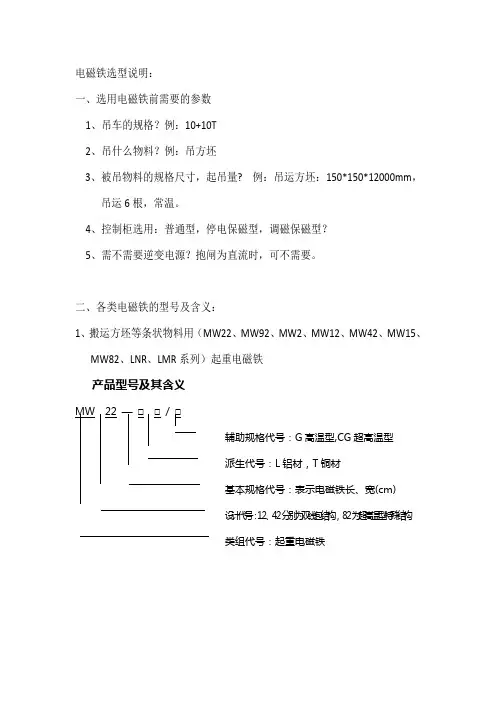
二、各类电磁铁的型号及含义:
1、搬运方坯等条状物料用(MW2
2、MW92、MW2、MW12、MW42、MW15、
MW82、LNR、LMR系列)起重电磁铁
产品型号及其含义
辅助规格代号:G高温型,CG超高温型
派生代号:L铝材,T铜材
基本规格代号:表示电磁铁长、宽(cm)
设计代号:12、42分别为双线包结构,82为超高温型特殊结构
类组代号:起重电磁铁
产品型号及含义
工作频率
辅助规格代号:“QS”表示潜水型
“1”表示常温型
“2”表示高温型
派生代号:“L”表示铝材,“T”表示铜材
基本规格代号:表示电磁铁直径(cm)
设计代号:5为圆形结构
61为椭圆结构
类组代号:起重电磁铁
辅助规格代号,“G”表示高温型
派生代号
基本规格代号,表示电磁铁起重能力(t)
设计代号
类组代号,起重电磁铁
注:MW1系列起重电磁铁散料型产品使用说明书同MW5系列。
产品型号及含义
表示铝材,T表示铜材
除铁器外极的外径(cm)
为圆形结构、84为矩形结构
起重电磁铁。
Dimensions: [mm]sectional drawing A-AScale - 3:17447462022744746202274474620227447462022T e m p e r a t u r eT T T 7447462022Further informationComponent Libraries:Altium_WE-TI (22d)Downloads_CADENCE_WE-TI (22a)CadStar_WE-TI (19b)Eagle_WE-TI (19c)Download_IGS_WE-TI_Typ_XSPSpice_WE-TI (23a)Download_STP_WE-TI-5075Spectre_WE-TI (23a)Design Kits:■Design Kit WE-TI Radial Leaded Wire InductorFree Sample Order:Order free samples of this article directly here!Tutorials:■Single Coil Inductors (PDF)REDEXPERT:Calculate losses for 7447462022 in REDEXPERTWürth Elektronik eiSos GmbH & Co. KGEMC & Inductive SolutionsMax-Eyth-Str. 174638 WaldenburgGermanyCHECKED REVISION DATE (YYYY-MM-DD)GENERAL TOLERANCE PROJECTIONMETHODTRi004.0002023-12-14DIN ISO 2768-1mDESCRIPTIONWE-TI Radial Leaded Wire WoundInductor ORDER CODE7447462022SIZE/TYPE BUSINESS UNIT STATUS PAGED RA FTCautions and Warnings:The following conditions apply to all goods within the product series of WE-TI of Würth Elektronik eiSos GmbH & Co. KG:General:•This electronic component was designed and manufactured for use in general electronic equipment.•Würth Elektronik must be asked for written approval (following the PPAP procedure) before incorporating the components into any equipment in fields such as military, aerospace, aviation, nuclear control, submarine, transportation (automotive control, train control, ship control), transportation signal, disaster prevention, medical, public information network, etc. where higher safety and reliability are especially required and/or if there is the possibility of direct damage or human injury.•Electronic components that will be used in safety-critical or high-reliability applications, should be pre-evaluated by the customer. •The component is designed and manufactured to be used within the datasheet specified values. If the usage and operation conditions specified in the datasheet are not met, the wire insulation may be damaged or dissolved.•Do not drop or impact the components, the component may be damaged.•Würth Elektronik products are qualified according to international standards, which are listed in each product reliability report. Würth Elektronik does not warrant any customer qualified product characteristics beyond Würth Elektroniks’ specifications, for its validity and sustainability over time.•The customer is responsible for the functionality of their own products. All technical specifications for standard products also apply to customer specific products.Product specific:Soldering:•The solder profile must comply with the technical product specifications. All other profiles will void the warranty.•All other soldering methods are at the customers’ own risk.Cleaning and Washing:•Washing agents used during the production to clean the customer application might damage or change the characteristics of the wire insulation, marking or plating. Washing agents may have a negative effect on the long-term functionality of the product. Potting:•If the product is potted in the costumer application, the potting material might shrink or expand during and after hardening. Shrinking could lead to an incomplete seal, allowing contaminants into the core. Expansion could damage the components. We recommend a manual inspection after potting to avoid these effects. Storage Conditions:• A storage of Würth Elektronik products for longer than 12 months is not recommended. Within other effects, the terminals may suffer degradation, resulting in bad solderability. Therefore, all products shall be used within the period of 12 months based on the day of shipment.•Do not expose the components to direct sunlight.•The storage conditions in the original packaging are defined according to DIN EN 61760-2.•The storage conditions stated in the original packaging apply to the storage time and not to the transportation time of the components. Packaging:•The packaging specifications apply only to purchase orders comprising whole packaging units. If the ordered quantity exceeds or is lower than the specified packaging unit, packaging in accordance with the packaging specifications cannot be ensured. Handling:•Violation of the technical product specifications such as exceeding the nominal rated current will void the warranty.•Applying currents with audio-frequency signals might result in audible noise due to the magnetostrictive material properties. •Due to heavy weight of the components, strong forces and high accelerations might have the effect to damage the electrical connection or to harm the circuit board and will void the warranty.•Please be aware that products provided in bulk packaging may get bent and might lead to derivations from the mechanical manufacturing tolerances mentioned in our datasheet, which is not considered to be a material defect.•The temperature rise of the component must be taken into consideration. The operating temperature is comprised of ambient temperature and temperature rise of the component.The operating temperature of the component shall not exceed the maximum temperature specified.These cautions and warnings comply with the state of the scientific and technical knowledge and are believed to be accurate and reliable.However, no responsibility is assumed for inaccuracies or incompleteness.Würth Elektronik eiSos GmbH & Co. KGEMC & Inductive SolutionsMax-Eyth-Str. 174638 WaldenburgGermanyCHECKED REVISION DATE (YYYY-MM-DD)GENERAL TOLERANCE PROJECTIONMETHODTRi004.0002023-12-14DIN ISO 2768-1mDESCRIPTIONWE-TI Radial Leaded Wire WoundInductor ORDER CODE7447462022SIZE/TYPE BUSINESS UNIT STATUS PAGE D RA FTImportant NotesThe following conditions apply to all goods within the product range of Würth Elektronik eiSos GmbH & Co. KG:1. General Customer ResponsibilitySome goods within the product range of Würth Elektronik eiSos GmbH & Co. KG contain statements regarding general suitability for certain application areas. These statements about suitability are based on our knowledge and experience of typical requirements concerning the areas, serve as general guidance and cannot be estimated as binding statements about the suitability for a customer application. The responsibility for the applicability and use in a particular customer design is always solely within the authority of the customer. Due to this fact it is up to the customer to evaluate, where appropriate to investigate and decide whether the device with the specific product characteristics described in the product specification is valid and suitable for the respective customer application or not.2. Customer Responsibility related to Specific, in particular Safety-Relevant ApplicationsIt has to be clearly pointed out that the possibility of a malfunction of electronic components or failure before the end of the usual lifetime cannot be completely eliminated in the current state of the art, even if the products are operated within the range of the specifications.In certain customer applications requiring a very high level of safety and especially in customer applications in which the malfunction or failure of an electronic component could endanger human life or health it must be ensured by most advanced technological aid of suitable design of the customer application that no injury or damage is caused to third parties in the event of malfunction or failure of an electronic component. Therefore, customer is cautioned to verify that data sheets are current before placing orders. The current data sheets can be downloaded at .3. Best Care and AttentionAny product-specific notes, cautions and warnings must be strictly observed. Any disregard will result in the loss of warranty.4. Customer Support for Product SpecificationsSome products within the product range may contain substances which are subject to restrictions in certain jurisdictions in order to serve specific technical requirements. Necessary information is available on request. In this case the field sales engineer or the internal sales person in charge should be contacted who will be happy to support in this matter.5. Product R&DDue to constant product improvement product specifications may change from time to time. As a standard reporting procedure of the Product Change Notification (PCN) according to the JEDEC-Standard inform about minor and major changes. In case of further queries regarding the PCN, the field sales engineer or the internal sales person in charge should be contacted. The basic responsibility of the customer as per Section 1 and 2 remains unaffected.6. Product Life CycleDue to technical progress and economical evaluation we also reserve the right to discontinue production and delivery of products. As a standard reporting procedure of the Product Termination Notification (PTN) according to the JEDEC-Standard we will inform at an early stage about inevitable product discontinuance. According to this we cannot guarantee that all products within our product range will always be available. Therefore it needs to be verified with the field sales engineer or the internal sales person in charge about the current product availability expectancy before or when the product for application design-in disposal is considered. The approach named above does not apply in the case of individual agreements deviating from the foregoing for customer-specific products.7. Property RightsAll the rights for contractual products produced by Würth Elektronik eiSos GmbH & Co. KG on the basis of ideas, development contracts as well as models or templates that are subject to copyright, patent or commercial protection supplied to the customer will remain with Würth Elektronik eiSos GmbH & Co. KG. Würth Elektronik eiSos GmbH & Co. KG does not warrant or represent that any license, either expressed or implied, is granted under any patent right, copyright, mask work right, or other intellectual property right relating to any combination, application, or process in which Würth Elektronik eiSos GmbH & Co. KG components or services are used.8. General Terms and ConditionsUnless otherwise agreed in individual contracts, all orders are subject to the current version of the “General Terms and Conditions of Würth Elektronik eiSos Group”, last version available at .Würth Elektronik eiSos GmbH & Co. KGEMC & Inductive SolutionsMax-Eyth-Str. 174638 WaldenburgGermanyCHECKED REVISION DATE (YYYY-MM-DD)GENERAL TOLERANCE PROJECTIONMETHODTRi004.0002023-12-14DIN ISO 2768-1mDESCRIPTIONWE-TI Radial Leaded Wire WoundInductor ORDER CODE7447462022SIZE/TYPE BUSINESS UNIT STATUS PAGE D RA FT。
Instruction ManualElectric Actuator / High Rigidity Slider Type Series LEJThe intended use of this Electrical Actuator is to convert an electrical input signal into mechanical motion.1 Safety InstructionsThese safety instructions are intended to prevent hazardous situations and/or equipment damage. These instructions indicate the level of potential hazard with the labels of “Caution,” “Warning” or “Danger.” They are all important notes for safety and must be followed in addition to International Standards (ISO/IEC) *1), and other safety regulations. *1)ISO 4414: Pneumatic fluid power - General rules relating to systems. ISO 4413: Hydraulic fluid power - General rules relating to systems.IEC 60204-1: Safety of machinery - Electrical equipment of machines. (Part 1: General requirements)ISO 10218-1: Manipulating industrial robots -Safety. etc.∙ Refer to product catalogue, Operation Manual and Handling Precautions for SMC Products for additional information. ∙ Keep this manual in a safe place for future reference.CautionCaution indicates a hazard with a low level of risk which, if not avoided, could result in minor or moderate injury.WarningWarning indicates a hazard with a medium level of riskwhich, if not avoided, could result in death or serious injury.DangerDanger indicates a hazard with a high level of risk which, ifnot avoided, will result in death or serious injury.Warning∙ This is a Class A product and it must not be used in residential premises.∙ Always ensure compliance with relevant safety laws and standards. All work must be carried out in a safe manner by a qualified person in compliance with applicable national regulations.2 SpecificationsLEJS40 / 63 series – Ball screw drive Note8) Note9) Note10)ModelLEJS40LEJS63 A c t u a t o r s p e c i f i c a t i o nStroke [mm] Note1) 200,300,400,500,600, 700,800,900,1000,1200 300,400,500,600,700,800,900,1000,1200,1500 Work load [kg] Note2)Horizontal 15 30 55 30 45 85 Vertical 3 5 10 6 10 20 Speed [mm/s] Note3)S t r o k e r a n g e0 to 500 1800 1200 600 1800 1200 600 501 to 600 1580 1050 520 1800 1200 600 601 to 700 1170 780 390 1800 1200 600 701 to 800 910 600 300 1390 930 460 801 to 900 720 480 240 1110 740 370 901 to 1000 580 390 190 900 600 300 1001 to 1100 480 320 160 750 500 250 1101 to 1200 410 270 130 630 420 210 1201 to 1300 - - - 540 360 180 1301 to 1400 - - - 470 310 150 1401 to 1500- - -410 270 1302 Specifications - continuedModel LEJS40 LEJS63A c t u a t o r s p e c i f i c a t i o nMaximum acceleration / deceleration [mm/s 2] 20,000 (refer to catalogue for limit according to work load and duty rate)Positionrepeatability [mm] Basic type ±0.02 Highprecision type±0.01 Lost motion[mm] Note4) Basic type 0.1 or lessHigh precision type0.05 or lessLead [mm] 24 16 8 30 20 10 Impact / Vibrationresistance [m/s 2] Note5) 50 / 20Drive method Ball screw Guide typeLinear guideAcceptable external resistance [N]20Operating temperature range [℃]5 to 40Operating humidity [%RH] 90 or less (no condensation)Regenerative optionMay be required by speed and work load.(refer to catalogue).E l e c t r i c a lMotor output [W] / size [mm] 100 / □40200 / □60Type of MotorAC servo motorL o c kLock Type Note6) No excitation operating type Holding force [N]LEJS *(S/T)* / LEJS *V * 67 / 67101 / 101 203 / 202 220 / 108 330 / 162 660 / 324 Power consumption [W] at 20℃ Note7)LEJS *(S/T)* / LEJS *V * 6.3 / 5.57.9 / 6Rated voltage [VDC]24 +0 / -10%LEJS63–M series – Ball screw drive Note8) Note9) Note10)ModelLEJS63*-*MA c t u a t o r s p e c i f i c a t i o nStroke [mm]Note1)790,890,990,1190,1490,1790 Work load[kg] Note2) Horizontal 30 45 85 Vertical6 10 20 Speed [mm/s] 1800 1200 600 Maximum acceleration / deceleration [mm/s 2]20,000 (refer to catalogue for limit accordingto work load and duty rate.)Positionrepeatability [mm] Basic type ±0.02High precision type±0.01 Lostmotion [mm] Note4) Basic type 0.1 or less High precision type 0.05 or lessLead [mm]3020 10Impact / Vibration resistance [m/s 2] Note5) 50 / 20 Drive method Ball screw Guide typeLinear guideAcceptable external resistance [N]20 Operating temperature range [℃]5 to 40Operating humidity [%RH] 90 or less (no condensation)Regenerative optionMay be required by speed and work load.(refer to catalogue).E l e c t r i c a lMotor output [W] / size [mm] 200 / □60Type of MotorAC servo motor L o c kLock Type Note6)No excitation operating type Holding force [N]LEJS *(S/T)* / LEJS *V * 220 / 108330 / 162 660 / 324Power consumption [W] at 20℃ Note7)LEJS *(S/T)* / LEJS *V * 7.9 / 6 Rated voltage [VDC]24 +0 / -10%2 Specifications - continuedLEJS100 series – Ball screw drive Note8) Note9) Note10)ModelLEJS100A c t u a t o r s p e c i f i c a t i o nStroke [mm] Note1)300,400,500,600,700,800,900,1000,1200,1500,2000,2500 Horizontalwork load [kg] 3000 (mm/s 2) 60 150 400 5000 (mm/s 2) 43 93 150 9800 (mm/s 2)22 36 - Verticalwork load [kg] 3000 (mm/s 2) 14 29 80 5000 (mm/s 2) 12 29 30 9800 (mm/s 2)8 9 - Speed[mm/s]S t r o k e r a n g e0 to 800 2300 1250 500 801 to 900 1900 950 380 901 to 1000 1600 800 320 1001 to 1100 1400 700 280 1101 to 1200 1200 600 240 1201 to 13001000 500 200 1301 to 1500900 450 180 1501 to 1600 800 400 160 1601 to 1700 700 350 140 1701 to 1800 600 300 120 1801 to 2000 500 250 100 2001 to 2300 400 200 80 2301 to 2500300 150 60Maximum acceleration / deceleration [mm/s 2]9,800 Position repeatability [mm] ±0.01Lost motion [mm] Note4) 0.05 or lessLead [mm]50 25 10Impact / Vibration resistance [m/s 2] Note5) 50 / 20Drive method Ball screw Guide typeLinear guide Operating temperature [℃] 5 to 40Operating humidity [%RH]90 or less (no condensation) Regenerative optionMay be required by speed and work load.(refer to catalogue).E l e c t r i c a lMotor output [W] / size [mm] 750 / □80Type of Motor AC servo motorL o c kLock TypeNote6)No excitation operating type Holding force [N] 240480 1220Power consumption [W] at 20℃ Note7)10 Rated voltage [VDC]24 0 / -10%Note1) Strokes other than the above are produced as a special order.Note2) Details are shown in “Speed-Work load graph (indication)” of catalogue. Note3) The allowable speed will be affected by the stroke length.Note4) A reference value for correcting an error in reciprocal operation.Note5) Impact resistance: No malfunction occurred when the actuator was tested with a droptester. In both axial and perpendicular direction to the lead screw (the test was performed with the actuator in the initial state).Vibration resistance: No malfunction occurred in a test ranging between 45 to 2000 Hz,when the actuator was tested in both an axial and perpendicular direction to the lead screw. (The test was performed with the actuator in the initial state.)Note6) Only applies to actuators supplied with lock.Note7) For the actuator with lock, please add the power consumption for the lock. Note8) Sensor magnet position is located at the centre of the table. Note9) Do not allow collisions at either end of the table travel range.In addition, when running the positioning operation, do not set within 2 mm of either end. Note10) Consult with SMC for the manufacture of intermediate strokes.(Manufacturable stroke range LEJS40/200 up to 1200mm, LEJS63/300 up to 1500mm, LEJS63*-*M/790 up to 1790mm, LEJS100/300 up to 2500mm).WeightModelLEJS40Stroke [mm] 200 300 400 500 600 700 800 900 1000 1200 Weight (kg) 5.6 6.47.17.98.7 9.4 10.2 11.0 11.7 13.3Lock weight(kg)0.2 (S2) / 0.3 (S6) / 0.2 (T6)Model LEJS63Stroke [mm] 300 400 500 600 700 800 900 1000 1200 1500 Weight (kg) 11.4 12.7 13.9 15.2 16.4 17.7 18.9 20.1 22.6 26.4 Lock weight(kg)0.4 (S3) / 0.7 (S7) / 0.4 (T7)2 Specifications - continuedModel LEJS63*-*M Stroke [mm] 790 890 990 1190 14901790 Weight (kg) 19.420.721.9 24.429.933.7Lock weight(kg)0.4 (S3) / 0.7 (S7) / 0.4 (T7)Model LEJS100Stroke [mm] 300 400 500 600 700 800 900 1000 1200 1500 2000 2500 Weight (kg) 22.5 24.6 26.7 28.8 30.9 33.0 35.1 37.1 41.3 47.6 58.1 68.5 Lock weight(kg)1.0LEJB series - Belt drive Note7) Note8) Note9)ModelLEJB40LEJB63A c t u a t o r s p e c i f i c a t i o nStroke [mm]Note1)200,300,400,500, 600,700,800,900, 1000,1200,1500,2000 300,400,500,600, 700,800,900,1000, 1200,1500,2000,3000Work load [kg]Horizontal20 (10 for stroke above1000 mm)30 Speed [mm/s] Note2)20003000Maximum acceleration /deceleration [mm/s 2] 20,000 (refer to catalogue for limit according towork load and duty rate)Position repeatability [mm] ±0.04 Lost motion [mm] Note3)0.1 or lessLead [mm]2742Impact / Vibration resistance [m/s 2] Note4) 50 / 20 Drive method Belt drive Guide type Linear guideAcceptable external resistance [N]20 Operating temperature [℃] 5 to 40Operating humidity [%RH] 90 or less (no condensation) Regenerative optionMay be required by speed and work load.(refer to catalogue).ModelLEJB40 LEJB63 E l e c t r i c a lMotor output [W] /size [mm] 100 / □40200 / □60Type of MotorAC servo motor L o c kLock Type Note5) No excitation operating type Holding force [N]LEJB *(S/T)* / LEJB *V * 60 / 59 189 /77 Power consumption [W] at 20℃ Note6)LEJB *(S/T)*/ LEJB *V * 6.3 / 5.57. 9 / 6Rated voltage [VDC]24 +0 / -10%Note1) Strokes other than the above are produced as a special order.Note2) Details are shown in “Speed-Work load graph (indication)” of catalogue. Note3) A reference value for correcting an error in reciprocal operation.Note4) Impact resistance: No malfunction occurred when the actuator was tested with a droptester. In both axial and perpendicular direction to the lead screw (the test was performed with the actuator in the initial state).Vibration resistance: No malfunction occurred in a test ranging between 45 to 2000 Hz,when the actuator was tested in both an axial and perpendicular direction to the lead screw. (The test was performed with the actuator in the initial state.)Note5) Only applies to actuators supplied with lock.Note6) For the actuator with lock, please add the power consumption for the lock. Note7) Sensor magnet position is located at the centre of the table. Note8) Do not allow collisions at either end of the table travel range.In addition, when running the positioning operation, do not set within 2 mm of either end. Note9) Consult with SMC for the manufacture of intermediate strokes.(Manufacturable stroke range LEJB40/200 up to 2000mm, LEJB63/300 up to 3000mm)WeightModel LEJB40Stroke [mm] 200 300 400 500 600 700 800 900 1000 1200 1500 2000 Weight (kg) 5.7 6.4 7.1 7.7 8.4 9.1 9.8 10.5 11.2 12.6 14.7 18.1Lock weight(kg) 0.2 (S2) / 0.3 (S6) / 0.2 (T6)ModelLEJB63Stroke [mm] 300 400 500 600 700 800 900 1000 1200 1500 2000 3000 Weight (kg) 11.5 12.7 13.8 15.0 16.2 17.4 18.6 19.7 22.1 25.7 31.6 43.4Lock weight(kg) 0.4 (S3) / 0.7 (S7) / 0.4 (T7)ORIGINAL INSTRUCTIONSRefer to Declaration of Conformity for relevant Directives3 Installation3.1 InstallationWarning∙Do not install the product unless the safety instructions have been read and understood.∙Do not use the product in excess of its allowable specification as listed in Section 2.∙When installing, inspecting or performing maintenance on the product, be sure to turn off the power supplies. Then, lock it so it cannot be tampered with while work is happening.∙Keep the flatness of the mounting surface to 0.1 mm maximum. Insufficient flatness of a work piece or actuator mounting surface can cause play in the guide and increased sliding resistance. In the case of overhang mounting (including cantilever), use a support plate or support guide to avoid deflection of the actuator body.∙When mounting the actuator, use all mounting holes.If all mounting holes are not used, this will not maintain the specified performance. e.g. the amount of displacement of the table will increase.∙When mounting the actuator, use screws with adequate length and tighten them with adequate torque.Tightening the screws with a torque higher than recommended may cause malfunction, whilst tightening with a torque lower than recommended can cause displacement of the mounting position, or in extreme conditions the actuator could become detached from its mounting position.Note1) When A is M thread, L is thread depth.∙In order to prevent the work piece fixing screws from damaging the table, use screws at least 0.5 mm shorter than the maximum thread depth.Longer screws can hit the body and cause operation failure.∙When mounting the actuator using the body mounting reference plane, use a positioning pin.Set the height of the pin to be 5 mm or more because of R chamfering. (recommended height: 6 mm). 3 Installation - continued3.2 EnvironmentWarning∙Do not use in an environment where corrosive gases, chemicals, saltwater or steam are present.∙Do not use in an explosive atmosphere.∙Do not expose to direct sunlight. Use a suitable protective cover.∙Do not install in a location subject to vibration or impact in excess ofthe product’s specifications.∙Do not mount in a location exposed to radiant heat that would resultin temperatures in excess of the product’s specificat ions.∙Prevent foreign particles from entering the product.3.3 MountingWarning∙Observe the required tightening torque for screws.Unless stated otherwise, tighten the screws to the recommendedtorque for mounting the product.∙Do not make any alterations to the product.Alterations made to this product may lead to a loss of durability anddamage to the product, which can lead to injury and damage to otherequipment and machinery.∙When an external guide is used, connect the moving parts of theproduct and the load in such a way that there is no interference atany point within the stroke.Do not scratch or dent the sliding parts of the table or mounting faceetc., by striking or holding them with other objects. The componentsare manufactured to precise tolerances, so that even a slightdeformation may cause faulty operation or seizure.∙Do not use the product until it has been verified that the equipmentcan be operated correctly.After mounting or repair, connect the power supply to the product andperform appropriate functional inspections to check it is mountedcorrectly.∙Do not use the product until it has been verified that the equipmentcan be operated correctly.After mounting or repair, connect the power supply to the product andperform appropriate functional inspections to check it is mountedcorrectly.∙Maintenance spaceAllow sufficient space for maintenance and inspection.3.4 LubricationCaution∙SMC products have been lubricated for life at manufacture, and donot require lubrication in service.∙If a lubricant is used in the system, refer to catalogue for details.∙The recommended grease is lithium grade No.2SMC grease packs are listed below.Applied Region Grease Pack Number Weight [g]Ball screwGuideDust seal bandGR-S-010 10GR-S-020 203.5 WiringWarning∙Adjustment, mounting or wiring changes should not be carried outbefore disconnecting the power supply to the product.Electric shock, malfunction and damage can result.∙Do not disassemble the cables.∙Use only specified cables.Use only specified cables otherwise there may be risk of fire anddamage.∙Do not connect or disconnect the wires, cables and connectors whenthe power is turned on.Caution∙Wire the connector correctly and securely.Check the connector for polarity and do not apply any voltage to theterminals other than those specified in the Operation Manual.3 Installation - continued∙Take appropriate measures against noise.Noise in a signal line may cause malfunction. As a countermeasureseparate the high voltage and low voltage cables, and shorten thewiring lengths, etc.∙Do not route input/output wires and cables together with power orhigh voltage cables.The product can malfunction due to noise interference and surgevoltage from power and high voltage cables close to the signal line.Route the wires of the product separately from power or high voltagecables.∙Take care that actuator movement does not catch cables.∙Operate with all wires and cables secured.∙Avoid bending cables at sharp angles where they enter the product.∙Avoid twisting, folding, rotating or applying an external force to thecable.Risk of electric shock, wire breakage, contact failure and loss ofcontrol of the product can result.∙Select “Robotic cables”in applications where cables are movingrepeatedly (encoder/ motor/ lock).Refer to the relevant operation manual for the bending life of thecable.∙Confirm correct insulation.Poor insulation of wires, cables, connectors, terminals etc. can causeinterference with other circuits. Also there is the possibility thatexcessive voltage or current may be applied to the product causingdamage.∙R efer to the auto switch references in “Best Pneumatics“ when anauto switch is to be usedLECSA (Pulse input / Positioning) driver3 Installation - continued3.6 Operating precautions∙Do not touch the motor whilst it is in operation. The surfacetemperature can increase to approximately 80°C. Energising alonecan also increase the temperature of the product. Thesetemperatures can cause burns.∙If the product is overheating, smoking or has caught fire, immediatelyshut the power supply off.∙If the product emits abnormal noise or vibrations, the product shouldbe immediately stopped and inspected as it may be mountedincorrectly, otherwise it can seriously damage the product.∙Do not touch rotating parts of the motor or moving parts of theactuator while in operation.4 How to Order∙For standard products, refer to the catalogue for the how to orderinformation.∙For special products, which include a suffix of “-X*”, “-DC*” or “-DK*”,then please refer to the customer drawing of that specific product.5 Outline Dimensions (mm)∙For standard products, refer to the catalogue for outline dimensions.∙For special products, which include a suffix of “-X*”, “-DC*” or “-DK*”,then please refer to the customer drawing of that specific product.6 Maintenance6.1 General MaintenanceCaution∙Not following proper maintenance procedures could cause theproduct to malfunction and lead to equipment damage.∙If handled improperly, compressed air can be dangerous.∙Maintenance of pneumatic systems should be performed only byqualified personnel.∙Before performing maintenance, turn off the power supply and besure to cut off the supply pressure. Confirm that the air is released toatmosphere.∙After installation and maintenance, apply operating pressure andpower to the equipment and perform appropriate functional andleakage tests to make sure the equipment is installed correctly.∙If any electrical connections are disturbed during maintenance,ensure they are reconnected correctly and safety checks are carriedout as required to ensure continued compliance with applicablenational regulations.∙Do not make any modification to the product.∙Do not disassemble the product, unless required by installation ormaintenance instructions.∙I ncorrect handling can cause an injury, damage or malfunction of theequipment and machinery, so ensure that the procedure for the taskis followed.∙Always allow sufficient space around the product to complete anymaintenance and inspection.Model Screw size Maximum tighteningtorque (Nm)A (mm) L (mm)Note1)LEJ*40 M5 3.0 φ5.5 36.5 LEJ*63 M6 5.2 φ6.8 49.5 LEJS100 M8 x 1.25 12.5 M8 16Model Screw size Maximum tighteningtorque (Nm)L (Maximum threaddepth) mmLEJ*40 M6 x 1 5.2 10 LEJ*63 M8 x 1.25 12.5 12 LEJS100 M8 x 1.25 12.5 16DriverMotor cableEncoder cableElectric actuator24VDCLock cableHostcontrolleretc.I/O connectorLECSB / LECSB-T (Pulse input) driverLECSC / LECSC-T (CC-Link) driverLECSS / LECSS-T (SSCNET) driverLECYM / LECYU (MECHATROLINK) driverDriverMotor cableEncoder cableElectric actuatorHostcontrolleretc.I/O connector24VDCActuator mounting Work piece mountingMounting reference planeDriverMotor cableEncoder cableElectric actuator24VDC Hostcontrolleretc.I/O connectorLock cable6 Maintenance - continued6.2 Periodical Maintenance∙Maintenance should be performed according to the table below:AppearanceCheckBelt Check Inspection before daily operation ✓Inspection every six months* ✓✓Inspection every 1,000km* ✓✓Inspection every 5 million cycles* ✓✓*whichever of these occurs first. ∙Following any maintenance, always perform a system check. Do not use the product if any error occurs, as safety cannot be assured if caused by any un-intentional malfunction.6.3 Appearance Check∙The following items should be visually monitored and ensure that the cylinder remains in good condition and there are no concerns flagged;・Loose Screws,・Abnormal level of dust or dirt,・Visual flaws/faults,・Check the cable connections,・Abnormal noises or vibrations,6.4 Belt Check∙If one of the 6 conditions below are seen, do not continue operating the cylinder, contact SMC immediately.・Tooth shaped canvas is worn out.Canvas fibre becomes “fuzzy”, rubber is removed, and the fibre gains a white colour. The lines of fibre become very unclear.・Peeling off or wearing of the side of the belt.The corner of the belt becomes round and frayed, with threadsbeginning to stick out.・Belt is partially cut.Belt is partially cut. Foreign matter could be caught in the teeth and cause flaws.・Vertical line of belt teeth.Flaw which is made when the belt runs on the flange.・Rubber back of the belt is softened and sticky.・Crack on the back of the belt.7 Limitations of Use7.1 Limited warranty and Disclaimer/Compliance Requirements∙Refer to Handling Precautions for SMC Products.8 Product disposalThis product should not be disposed of as municipal waste. Check your local regulations and guidelines to dispose of this product correctly, in order to reduce the impact on human health and the environment. 9 ContactsRefer to or www.smc.eu for contacts.URL : http// (Global) http// (Europe) 'SMC Corporation, Akihabara UDX15F, 4-14-1, Sotokanda, Chiyoda-ku, Tokyo 101 0021Specifications are subject to change without prior notice from the manufacturer. © 2020 SMC Corporation All Rights Reserved.Template DKP50047-F-085I。
Eaton 192766Eaton Moeller® series MSC-DMEA DOL starter, 380 V 400 V 415V: 1.5 kW, Ir: 1 - 4 A, Connection to SmartWire-DT: yes, 24 V DC,DCGeneral specificationsEaton Moeller® series MSC-DMEA DOLstarter1927664015081935109149.5 mm206 mm45 mm0.998 kgVDE 0660IEC/EN 60947-4-1MSC-DMEA-4-M17(24VDC)Product Name Catalog NumberEANProduct Length/Depth Product Height Product Width Product Weight Certifications Model CodeShort-circuit releaseTemperature compensated overload protection AdjustableScrew terminalsYesIn conjunction with PKE-SWD-32 SmartWire DT PKE module700 (Class 10) AC-4 cycle operation, Main conducting paths 900 (Class 15) AC-4 cycle operation, Main conducting paths 1000 (Class 20) AC-4 cycle operation, Main conducting paths For all combinations with an SWD activation, you need not adhere to the minimum current flow times and minimum cut-out periods.500 (Class 5) AC-4 cycle operation, Main conducting paths Note: Going below the minimum current flow time can cause overheating of the load (motor).≤ 500 ms, main conducting paths, AC-4 cycle operationIP20NEMA OtherDirect starterDIN rail11 A4 AIIIFitted with: Functions ClassConnectionConnection to SmartWire-DTCurrent flow times - minCut-out periods - minDegree of protectionModelMounting methodNumber of auxiliary contacts (normally closed contacts) Number of auxiliary contacts (normally open contacts) Overload release current setting - minOverload release current setting - maxOvervoltage category3Other bus systems6000 V ACAlso motors with efficiency class IE3 Starter with electronic trip unitDC Max. 2000 m -25 °C55 °C4 A4 A4 A0.75 kW3.6 kW2.2 kW230 - 690 V AC100000 A 186 A 0 V 0 V 0 V 0 V 24 VPollution degreeProtocolRated impulse withstand voltage (Uimp) Suitable forTypeVoltage type AltitudeAmbient operating temperature - minAmbient operating temperature - maxRated operational current (Ie)Rated operational current (Ie) at AC-3, 380 V, 400 V, 415 V Rated operational current (Ie) at AC-3, 500 VRated operational power at AC-3, 220/230 V, 50 HzRated operational power at AC-3, 380/400 V, 50 HzRated operational power at AC-3, 500 V, 50 HzRated operational voltageRated conditional short-circuit current (Iq), type 2, 380 V, 400 V, 415 VShort-circuit release (Irm) - max Rated control supply voltage (Us) at AC, 50 Hz - min Rated control supply voltage (Us) at AC, 50 Hz - max Rated control supply voltage (Us) at AC, 60 Hz - min Rated control supply voltage (Us) at AC, 60 Hz - max Rated control supply voltage (Us) at DC - minRated control supply voltage (Us) at DC - max24 V10.2.2 Corrosion resistanceMeets the product standard's requirements.10.2.3.1 Verification of thermal stability of enclosuresMeets the product standard's requirements.10.2.3.2 Verification of resistance of insulating materials tonormal heatMeets the product standard's requirements.10.2.3.3 Resist. of insul. mat. to abnormal heat/fire by internalelect. effectsMeets the product standard's requirements.10.2.4 Resistance to ultra-violet (UV) radiationMeets the product standard's requirements.10.2.5 LiftingDoes not apply, since the entire switchgear needs to beevaluated.10.2.6 Mechanical impactDoes not apply, since the entire switchgear needs to beevaluated.10.2.7 InscriptionsMeets the product standard's requirements.10.3 Degree of protection of assembliesDoes not apply, since the entire switchgear needs to beevaluated.10.4 Clearances and creepage distancesMeets the product standard's requirements.10.5 Protection against electric shockDoes not apply, since the entire switchgear needs to beevaluated.10.6 Incorporation of switching devices and componentsDoes not apply, since the entire switchgear needs to beevaluated.10.7 Internal electrical circuits and connectionsIs the panel builder's responsibility.10.8 Connections for external conductorsIs the panel builder's responsibility.10.9.2 Power-frequency electric strengthIs the panel builder's responsibility.Eaton Corporation plc Eaton House30 Pembroke Road Dublin 4, Ireland © 2023 Eaton. All rights reserved. Eaton is a registered trademark.All other trademarks areproperty of their respective owners./socialmediaIs the panel builder's responsibility.Is the panel builder's responsibility.The panel builder is responsible for the temperature rise calculation. Eaton will provide heat dissipation data for the devices.Is the panel builder's responsibility. The specifications for the switchgear must be observed.Is the panel builder's responsibility. The specifications for the switchgear must be observed.The device meets the requirements, provided the information in the instruction leaflet (IL) is observed.Simple, flexible and safe! Distribution system for motor-starter combinationsMotor Starters in System xStart - brochureSave time and space thanks to the new link module PKZM0-XDM32ME Product Range Catalog Switching and protecting motors eaton-manual-motor-starters-msc-d-dol-starter-dimensions-004.eps eaton-general-ie-ready-dilm-contactor-standards.epseaton-manual-motor-starters-msc-d-dol-starter-3d-drawing-005.eps DA-CE-ETN.MSC-DMEA-4-M17(24VDC)IL034054ZU WIN-WIN with push-in technology msc_dme_bg2.stp msc_dme_bg2.dwg eaton-manual-motor-starters-msc-d-dol-starter-wiring-diagram.eps10.9.3 Impulse withstand voltage 10.9.4 Testing of enclosures made of insulating material 10.10 Temperature rise10.11 Short-circuit rating10.12 Electromagnetic compatibility10.13 Mechanical functionBrochuresCataloguesDrawingseCAD modelInstallation instructions Installation videosmCAD model Wiring diagrams。
Eaton 192751Eaton Moeller® series MSC-DM DOL starter, 380 V 400 V 415 V: 11 kW, Ir= 20 - 25 A, 24 V DC, DCGeneral specificationsEaton Moeller® series MSC-DM DOL starter19275197.5 mm197 mm 45 mm 0.85 kgVDE 0660 IEC/EN 60947-4-1MSC-DM-25-M25(24VDC)Product NameCatalog Number Product Length/Depth Product Height Product Width Product Weight Certifications Model CodeShort-circuit releaseTemperature compensated overload protection CLASS 10 AScrew terminalsNoIP20NEMA OtherDirect starterDIN rail120 A25 AIII36000 V ACAlso motors with efficiency class IE3 Starter with Bi-Metal releaseDCFitted with: Functions ClassConnectionConnection to SmartWire-DTDegree of protectionModelMounting methodNumber of auxiliary contacts (normally closed contacts) Number of auxiliary contacts (normally open contacts) Overload release current setting - minOverload release current setting - maxOvervoltage categoryPollution degreeRated impulse withstand voltage (Uimp)Suitable forTypeVoltage typeMax. 2000 m -25 °C55 °C 21.7 A25 A5.5 kW11 kW230 - 415 V AC50000 A 388 A 0.5 W 0 V0 V0 V0 V 24 V 24 VMeets the product standard's requirements. Meets the product standard's requirements.Simple, flexible and safe! Distribution system for motor-starter combinationsDA-DC-00004911.pdfDA-DC-00004879.pdfAltitudeAmbient operating temperature - min Ambient operating temperature - max Rated operational current (Ie)Rated operational current (Ie) at AC-3, 380 V, 400 V, 415 V Rated operational power at AC-3, 220/230 V, 50 HzRated operational power at AC-3, 380/400 V, 50 HzRated operational voltageRated conditional short-circuit current (Iq), type 2, 380 V, 400 V, 415 VShort-circuit release (Irm) - max Power consumption (sealing) at DCRated control supply voltage (Us) at AC, 50 Hz - min Rated control supply voltage (Us) at AC, 50 Hz - max Rated control supply voltage (Us) at AC, 60 Hz - min Rated control supply voltage (Us) at AC, 60 Hz - max Rated control supply voltage (Us) at DC - minRated control supply voltage (Us) at DC - max10.2.2 Corrosion resistance10.2.3.1 Verification of thermal stability of enclosures10.2.3.2 Verification of resistance of insulating materials to normal heat BrosjyrerDeclarations of conformityMeets the product standard's requirements.Meets the product standard's requirements.Meets the product standard's requirements.Does not apply, since the entire switchgear needs to be evaluated.Does not apply, since the entire switchgear needs to be evaluated.Meets the product standard's requirements.Does not apply, since the entire switchgear needs to be evaluated.Meets the product standard's requirements.Does not apply, since the entire switchgear needs to be evaluated.Does not apply, since the entire switchgear needs to be evaluated.Is the panel builder's responsibility.Is the panel builder's responsibility.Is the panel builder's responsibility.Is the panel builder's responsibility.Is the panel builder's responsibility.The panel builder is responsible for the temperature rise calculation. Eaton will provide heat dissipation data for the devices.DA-CE-ETN.MSC-DM-25-M25(24VDC)IL034054ZUeaton-manual-motor-starters-device-msc-d-dol-starter-wiring-diagram.epsmsc_dm_bg2.stpmsc_dm_bg2.dwgeaton-manual-motor-starters-msc-d-dol-starter-dimensions-003.eps eaton-manual-motor-starters-msc-d-dol-starter-3d-drawing-004.eps eaton-manual-motor-starters-mounting-msc-d-dol-starter-3d-drawing.eps10.2.3.3 Resist. of insul. mat. to abnormal heat/fire by internal elect. effects10.2.4 Resistance to ultra-violet (UV) radiation10.2.5 Lifting10.2.6 Mechanical impact10.2.7 Inscriptions10.3 Degree of protection of assemblies10.4 Clearances and creepage distances10.5 Protection against electric shock10.6 Incorporation of switching devices and components10.7 Internal electrical circuits and connections10.8 Connections for external conductors10.9.2 Power-frequency electric strength10.9.3 Impulse withstand voltage10.9.4 Testing of enclosures made of insulating material10.10 Temperature rise eCAD model Installeringsinstruksjoner KoblingsskjemamCAD model TegningerEaton Corporation plc Eaton House30 Pembroke Road Dublin 4, Ireland © 2023 Eaton. Med enerett.Eaton is a registered trademark.All other trademarks are property of their respectiveowners./socialmediaIs the panel builder's responsibility. The specifications for the switchgear must be observed.Is the panel builder's responsibility. The specifications for the switchgear must be observed.The device meets the requirements, provided the information in the instruction leaflet (IL) is observed.10.11 Short-circuit rating10.12 Electromagnetic compatibility10.13 Mechanical function。