10G-SFP光模块在超高清LED显示控制系统的应用
- 格式:pdf
- 大小:320.84 KB
- 文档页数:8

视频SFP光模块全解在小型光纤网络建设中,SFP光模块起着至关重要的作用。
市场上有不同种类的SFP光模块,例如1000BASE-SX SFP,1000BASE-LX / LH SFP,1000BASE-T铜SFP。
除此之外,还有一种主要用于视频传输的SFP光模块,如下图。
视频SFP光模块基础介绍视频SFP光模块也被称为数字视频光模块或SDI(串行数字接口的缩写)视频光模块,是一种小型可热插拔的光模块,与光缆一起搭配使用。
为什么需要使用视频SFP光模块?因为随着大容量高清和超高清(UHD)数字视频广播的快速发展,网络传输需要一种具备高性能且能传输视频图像的光模块。
视频SFP光模块可用在SDI设备(或SDI接口)上,传输SDI视频病理信号,有效确保视频传输的质量。
视频SFP光模块的类型视频SFP光模块可根据不同层面划分为不同类型。
根据传输速率的不同可分为3G-SDI SFP,6G-SDI SFP,12G-SDI SFP;根据是否合乎规范标准分为MSA视频SFP光模块和非MSA视频SFP光模块;根据工作波长的不同分为普通SFP视频光模块和CWDM SFP视频光模块;根据传输距离的不同分为短距视频SFP光模块、中距视频SFP 光模块和长距视频SFP光模块。
如何使用视频SFP光模块由于视频SFP光模块既能完成光信号到数字信号的转换,也能完成数字信号到光信号的转换,因此它们通常被用于高清摄像机或监视器系统以及广播视频传输中。
下面以3G-SDI SFP为例将使用指南。
高清摄像头或监控器系统中使用的视频SFP模块通常,高清摄像机或监视器系统中有多个高清终端设备,因此我们可以将一个高清视频矩阵用作一端,该矩阵提供多个视频SFP端口,另一端提供多个HD-SDI设备。
将3G-SDI光模块分别插入设备,然后通过光纤将两端的SDI SFP光模块连接起来。
布线图如下图所示。
用于广播视频传输应用的视频SFP光模块由于广播视频传输应用需要高密度布线,因此通常会使用带有高密度视频SFP端口的HD-SDI设备。

10g 光模块标准光模块是光纤通信系统中的关键部件,它的主要功能是将电信号转换为光信号,或将光信号转换为电信号。
10G光模块是光模块的一种,其传输速率为10Gbps,是目前数据中心、云计算、大数据等领域广泛应用的光模块类型。
10G光模块的标准主要包括以下几个方面:1. 接口标准:10G光模块的接口标准主要有SFP+、QSFP28和CFP4等。
其中,SFP+是最常见的一种,它的体积较小,适用于大多数设备。
QSFP28和CFP4则适用于需要更高带宽的设备。
2. 传输距离:10G光模块的传输距离主要取决于光纤的类型。
对于单模光纤,10G光模块的最长传输距离可以达到40公里。
对于多模光纤,10G光模块的最长传输距离可以达到550米。
3. 波长标准:10G光模块的波长标准主要有850nm和1310nm两种。
其中,850nm波长的10G光模块适用于短距离传输,而1310nm波长的10G光模块适用于长距离传输。
4. 功耗标准:10G光模块的功耗标准主要由IEEE 802.3ba 定义。
该标准规定了10G光模块的最大功耗为7.5W,这是为了满足数据中心节能减排的需求。
5. 温度标准:10G光模块的工作温度范围通常为-40℃到85℃。
这是为了保证在各种恶劣环境下,10G光模块都能正常工作。
6. 尺寸标准:10G光模块的尺寸标准主要由JEDEC定义。
例如,SFP+的尺寸为7mm x 5mm,而QSFP28的尺寸为28mm x 28mm。
7. 性能标准:10G光模块的性能标准主要由ITU-T G.959.1定义。
该标准规定了10G光模块的最小和最大插入损耗、最小和最大回波损耗等参数。
以上就是10G光模块的主要标准。
在选择和使用10G光模块时,需要根据实际需求和应用环境,选择合适的接口标准、传输距离、波长标准、功耗标准、温度标准、尺寸标准和性能标准。
同时,还需要注意定期对10G光模块进行维护和检查,以确保其正常运行。
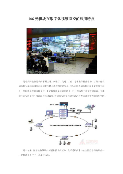
10G光模块在数字化视频监控的应用特点随着安防监控需求的不断上升,在银行、交通、工业、零售业等行业市场,以数字化视频监控为基础的网络化视频监控技术将获得长足发展。
作为中国视频监控市场未来发展方向之一的网络化视频监控系统,未来将继续保持强劲增长,行业整体处于高速发展阶段。
光模块作为安防监控不可或缺的重要设置,将随着安防监控运用需求的发展具有更大的市场空间。
近十年来,随着安防领域的拓展和技术的延伸,光纤通讯技术与安全防范学科的结晶——光模块也走过了十多年的历程。
光模块在安全防范领域中的应用从最初的调制技术到数字化、集成化、网络化、智能化、个性化,已逐渐成为安全防范领域信息传输不可或缺的部分。
光端机以光导纤维为传输平台,其拥有在有线传输领域中无可比拟的几大大优势:1、光纤传输频带宽,容量大,可达到太赫级;2、传输损耗低,可达到百公里无中继传输;3、不是电导体,不受电磁干扰,安全保密性能极好;4、光纤资源丰富,属非金属资源,稍作预留则可节省相当多的重复建设费用。
1920×1080超高清视频监控传输专用单纤10G SFP+光模块国内光模块的研发与生产不断地引入新技术、新理念,紧跟安防行业发展的潮流,其安全性、功能性、实用性、稳定性得到了长足的发展。
如今市场上推出的视频监控光传输多业务平台,在诸多国家重点安全防范工程建设中的成功运用,说明光模块已成为安全防范工程中传输部分的关键环节。
10G光模块在视频监控应用中的主要特点是:1、信息接口丰富,同时在一芯光纤上双向传输多路视频、音频、异步数据、模拟量、开关量、E1、以太网、电话等信号,成为主要的信息枢纽;2、主频千兆光传输,实现非压缩实时同步传输,高逼真,低误码,保证信息的及时、完整、准确;3、工业级设计,全表面贴装技术,安全性能高;4、透明协议传输,即插即用的电路设计,有很好的兼容性和扩展性;5、信号指示灯状态直接反映设备运状况,使用方便;6、有自愈环保护功能和故障告警显示功能,便于维护;7、有很强的人机交互性,可编程控制,便于管理和升级;8、个性化设计:军用保护色外观、防水封装、安装尺寸订做等。

基于SFP光模块控制系统的设计和实现王妮;侯韶华【摘要】设计、实现了一种完成光模块自适应功能的系统,且能够对SFP光模块一系列工作状态参数进行实时监测.此系统简化了对光模块的监控维护工作,并能简单快速地对光模块的内部存储单元进行读写,以满足其自适应功能的要求.【期刊名称】《光通信技术》【年(卷),期】2010(000)009【总页数】3页(P36-38)【关键词】SFP光模块;Ⅰ2C总线;自适应;实时监测;仿真【作者】王妮;侯韶华【作者单位】南京邮电大学,南京,210003;南京邮电大学,南京,210003【正文语种】中文【中图分类】TP210 引言在光通信产品中,光模块占有重要的地位。
随着技术的发展以及系统需求的变化,光模块也在不断的更新换代。
SFP(Small Form Pluggable)光模块体积比GBIC模块减少一半,可以在相同的面板上配置多出一倍以上的端口数量[1]。
另外,SFP 光模块还可以支持热拔插等功能,所以在现在的光通信产品中,SFP光模块越来越得到青睐,已经得到普遍使用。
同时,在现有的各种网络中所需要的光收发一体模块种类越来越多,要求也越来越高。
为了满足系统不断增长的需求,光模块正不断向标准化、小型化、智能化发展。
智能SFP模块,即采用数字诊断功能的SFP光模块,是各厂商技术升级换代的标志性产品。
它可以实现网络管理单元实时监测收发模块的温度、供电电压、激光偏置电流,以及发射和接收光功率。
这些参量的测量,可以帮助管理单元找出光纤链路中发生故障的位置,简化传输系统的维护工作,提高系统的可靠性[2]。
为此,本文设计了一种光模块自适应功能系统。
1 智能SFP光模块及存储单元基本原理1.1 光模块内部结构设计图1给出了SFP光模块的结构图。
RD、TD是数字信号的输入输出端口;LOS TXFAULT信号为出错报警信号;TXDIS为输出端口的控制信号。
图1 SFP光模块内部结构图光模块内部的EEPROM会存储光模块的基本信息,包括光模块的生产厂家,接口类型,序列号;还会存储光模块的各种参数,包括报警和警告门限;激光发射器的光功率、偏置电流、电源电压和温度的检测信息等都会通过A/D转换芯片转换为数字信息,也存储到EEPROM中[3],如图2所示。

10Gbs XFP光收发模块的设计与实现的开题报告一、选题背景随着现代通信技术的飞速发展,网络传输速率越来越高,数据中心、企业和运营商需要更快的传输速率来满足其不断增长的带宽需求。
因此,10Gbps通信标准越来越受到关注和采用。
在10Gbps网络中,光收发模块是至关重要的工具,它能够将电信号转换成光信号,并且将光信号转换成电信号,从而实现数据的传输。
XFP光收发模块是一种重要的光收发器,其具有体积小、传输速率快、灵活性强等优点,已经被广泛应用于数据中心和企业网络。
二、选题目的本文的目的是设计和实现一个10Gbps的XFP光收发模块,以满足目前市场对于高速光收发模块的需求。
具体的目标如下:1.了解XFP光收发器的基本原理和相关技术。
2.设计、制作并测试XFP光收发模块的电路原理图和PCB设计。
3.对设计的XFP光收发模块进行性能测试和可靠性测试,评估其性能和可靠性。
三、研究内容1. XFP光收发器的技术研究与分析:对XFP光收发器的基本原理、技术规范和标准、电气接口等进行详细分析和研究。
2. XFP光收发模块的电路设计:基于XFP光收发器的技术规范和标准,设计一个10Gbps的XFP光收发模块,采用高速数字解调器和模数转换器、低噪声放大器和多重检测电路等电路设计。
3. PCB设计和制作:在电路布局和原理图的基础上,设计和制作XFP光收发模块的PCB。
4. 性能测试和可靠性评估:对设计的XFP光收发模块进行性能测试和可靠性评估,包括传输距离、传输速率、信噪比等测试。
四、预期成果本文的预期成果如下:1.了解XFP光收发器的基本原理和基础知识。
2.熟悉XFP光收发器的技术规范和标准。
3.设计一个10Gbps的XFP光收发模块。
4.完成XFP光收发模块的PCB设计和制作。
5.对设计的XFP光收发模块进行性能测试和可靠性评估。
五、研究方法1. 理论研究法:查阅相关文献,学习和了解XFP光收发器的基本原理和技术规范和标准等。

User GuideTN-10GSFP-xxxSFP Transceiver Modules•Hot-Pluggable SFP Optical Transceiver•Digital Diagnostic Function•Class 1 Laser International Safety Standard IEC-60825 Compliant•Compatible with Small Form Factor Pluggable Multi-Sourcing Agreement (MSA)Contents Introduction (1)Description (1)Specifications (2)Optical Specifications (2)Application: Fiber Connections with SFPs (2)SFP Unpacking (3)SFP Installation (3)Installing an SFP Module (3)Fiber Cable Physical Characteristics (4)Connecting Fiber Cables (4)Removing an SFP Module (5)Diagnostic Monitoring Interface (DMI) (6)DDMI (Digital Diagnostics Monitoring Interface) (7)Contact Us (8)For More Information (8)Compliance Information (8)Record of Revisions (9)IntroductionThe Transition Networks TN-10GSFP-xxx-TMs series small form factorpluggable (SFP) transceiver modules are designed to install in any SFP slot,and connect multimodeor single mode fiber-optic cable to the network throughthe SFP connector. The TN-10GSFP-xxx-TMs are designed for bi-directional,serial-optical data communications up to 10.5 Gbps.DescriptionAll of Transition’s SFPs and XFPs are compliant with the Multi-Sourcing Agreement (MSA) ensuring interoperability with all other MSA compliant networking devices.MSA Compliant 10G SFP+TN-10GSFP-SR: Compliant with IEEE 802.3ae 10GBASE-SR/SW. Link Length up to 300 m with OM3 multi-mode fiber; 82 m with OM2 multi-mode fiber; 33 m with OM1 multimode fiber.TN-10GSFP-LRx: Compliant with IEEE 802.3ae 10GBASE-LR/LW. Maximum Link Length of 70 KM.TN-10GSFP-LRxM: TN-10GSFP-LR1M (10km), TN-10GSFP-LR4M (40km), TN-10GSFP-LR8M (80Km), TN-10GSFP-LR8M-Cxx (multiple CWDM wavelengths - 47, 49, 51, 53, 55, 57, 59, 61). Compliant with IEEE802.3ae and IEEE802.3z.TN-10GSFP-LRxM-Dxx: TN-10GSFP-LR4M-D21 thru TN-10GSFP-LR4M-D60 and TN-10GSFP-LR8M-D21 thru TN-10GSFP-LR8M-D60: Compliant with IEEE802.3ae and IEEE802.3z. Channels 21-60 supported (e.g., TN-10GSFP-L4RM-D47 (40km) and TN-10GSFP-LR8M-D49 (80km)).SpecificationsThe TN-10GSFP-xxx was designed to meet these standards and specifications:Transition Networks' SFP modules fully comply with Multi-Sourcing Agreement (MSA). This compliance allows our SFP modules to be used in other MSA compliant SFP platforms without any problems.Optical SpecificationsThe Optical Spec for all Transition Networks’ SFPs are listed and maintained in a separate document at https:///sfp.pdf.Application: Fiber Connections with SFPsSFPs are used with Gigabit Ethernet Switches and Routers, Fibre Channel Switch Infrastructure, xDSL applications, Metro Edge Switching, etc.SFP UnpackingBefore you start installing the TN-10GSFP-xxx, verify that thepackage contains the following items:o One TN-10GSFP-xxxo Two protective foam pieceso One Documentation PostcardPlease notify your sales representative immediately if any of theabove items are missing or damaged. Save the packaging forpossible future use.SFP InstallationCautions•The SFP tranceiver module is keyed to only be installed one way. However, if forced the wrong way, damage may occur. •Avoid getting dust or other contaminants into the fiber bore of the SFP transceiver module, as this will cause the optics to not operate properly. • Be sure to clean the optic surfacees of the optical fiber before you plug them back in to the opticalbores of another SFP transceiver module. See the Fiber Optic Association, Inc. Cleaning Fiber Optic Connections page on the FOA website for more information.Installing an SFP Module1. Attach an ESD-preventive wrist strap to your wrist and to the ESD ground connector or a bare metalsurface on your chassis.2. Remove the SFP transceiver module from its protective packaging. Note: Do not remove the opticalbore dust plugs until directed to do so in a later procedure.3. Check the slot orientation. Note that for some devices (e.g., S4224) some slots are “upside down”compared to other slots.4. Position the SFP device at the desired installation slot, with the label facing correctly.5. Carefully slide the SFP device into the slot, aligning it with the internal installation guides. Triangleindicates bottomof SFP cageSFP Module Label side topof SFP moduleBaleClasp SwitchFully Inserted SFPSwitch6. Ensure that the SFP device is firmly seated against the internal mating connector. To verify that theSFP is seated and latched properly:a. Grasp the SFP by the sides and try to remove it without releasing the latch.b. If the SFP can not be removed, it is installed and seated properly. If the SFP can be removed,reinsert it and press harder with your thumb; repeat if necessary until it is latched securely into the socket.7. Connect the fiber cable to the fiber port connector of the SFP device. Make sure the SFP releaselatch is in the up (closed) position when you insert the cable connector into the SFP.8. Remove the dust plug from the connector. Save the dust plug for future use.9. Attach an appropriate cable into the SFP module port.10. Attach the other end of the cable into the other device.11. Observe the status LED(s). See the related manual for details.Fiber Cable Physical CharacteristicsThe fiber cable physical characteristics must meet or exceed IEEE 802.3ae specifications:•Single mode fiber (recommended): 9 μm•Multimode fiber (recommended): 62.5/125 μm•Multimode fiber (optional): 100/140, 85/140, 50/125 μmWarning: Visible and invisible laser radiation when open. DO NOT stare into laser beam or view directly with optical instruments. Failure to observe this warning could result in damage to your eyes or blindness. Connecting Fiber CablesTo install the fiber cable, do the following:1. Locate the appropriate fiber cable.2. Install the cable as shown below.Removing an SFP ModuleCaution: Be careful when removing the SFP or SFP+ from a device. Some SFP transceiver module temperatures may exceed 160°F (70°C) and be too hot to touch with bare hands. Note: • Do not remove and replace the SFP modules more often than necessary; excessive SFP removing and replacing can shorten the SFPs useful life.1. Attach an ESD-preventive wrist strap to your wrist and to the ESD ground connector or a bare metalsurface on your chassis.2. For future reattachment of fiber-optic cables, note which connector plug is send (TX) and which isreceive (RX).3. Remove the SFP transceiver module:a. SFP with an actuator button latch: gently press the actuator button on the front of the SFPtransceiver module until it clicks and the latch mechanism releases the SFP transceiver module from the socket connector. Grasp the actuator button between your thumb and index finger, and carefully pull the SFP transceiver module straight out of the module slot.b. SFP with a bail clasp latch: pull the latch out and down to eject the SFP transceiver module fromthe socket connector. If the bail clasp latch is obstructed and you cannot use your index finger to open it, use a small, flat-blade screwdriver or other long, narrow instrument to open the bail clasp latch. Grasp the SFP transceiver module between your thumb and index finger, and carefully remove it from the socket.4. Replace the Dust Plug.5. Place the removed SFP/SFP+ transceiver module in an antistatic bag or other protective package.Diagnostic Monitoring Interface (DMI)The following DMI port screen and explanation table contains brief definitions of the DMI support offered on some (SFP Transceiver Modules. For further information, see the help option on the CPSMM-xxx, SNMP agent, or Transition Networks Focal Point or ION System GUI. Note: This feature is not availableon all devices and may vary between products.DMI Parameter DescriptionDMI Rx Power Measured receive optical power in microwatts and in decibels relative to 1mW. DMI Rx PowerAlarmAlarm status of measured receive optical power.DMI Temp Internally measured temperature of transceiver in degrees Celsius and degrees Farenheit.DMI Temp Alarm Alarm status for internally measured temperature of the transceiver. DMI Bias Current Measured transmit bias current in microamperes.DMI Bias Alarm Alarm status for measured transmit bias current for the interface.DMI Tx Power Measured transmit power in microwatts and in decibels relative to 1mW. DMI Tx Power Alarm Alarm status of measured transmit power.Rx Power Intrusion Threshold Tells the converter to stop passing traffic when the receive power drops below the new threshold. This feature is sometimes referred to as 'Intrusion Detection,' since tapping into a fiber to intercept traffic leads to a reduction in receive power. This value can be entered in microwatts or in decibels relative to 1mW.TN-SFP distances, TX power, RX power, and link budgets can be found on Transition Netwoks’ website, document “SFP/XFP Fiber and Copper Connectors.” See https:///sfp.pdf.The fiber optic transmitters on this device meet Class I Laser safety requirements per IEC-825/CDRH standards and comply with 21 CFR1040.10 and 21CFR1040.11.WARNING: Visible and invisible laser radiation when open. Do not stare into the beam or view the beam directly with optical instruments. Failure to observe this warning could result in an eye injury or blindness. IMPORTANT: Copper based media ports such as Twisted Pair (TP) Ethernet, USB, RS232, RS422,RS485, DS1, DS3, Video Coax, etc., are intended to be connected to intra-building (inside plant) link segments that are not subject to lightening transients or power faults. Copper-based media ports such as Twisted Pair (TP) Ethernet, USB, RS232, RS422, RS485, DS1, DS3, Video Coax, etc., are NOT to be connected to inter-building (outside plant) link segments that are subject to lightening transients or power faults.DDMI (Digital Diagnostics Monitoring Interface)DDMI (Digital Diagnostics Monitoring Interface) provides enhanced digital DMI for optical transceivers which allows real time access to device operating parameters.The following DMI port screen and explanation table contains brief definitions of the DDMI support offered on some Small Form Factor Pluggable (SFP) Transceiver Modules. For further information, see the help option or User Guide for the S3290, S4140, S4212, and S4224. Note: This feature is not available on all devices and functionality may vary between products.The Transceiver Information and DDMI Information sections are described below. DDMI ParameterDescription DMIRx Power (uW) Intrusion Threshold; a level for Rx Power on the Fiber port. If the DMI read value falls below the preset value, an intrusion is detected, and a trap is generated. The default is 0 uW. The range is 0 - 65,535 uW. PortThe device’s port number. VendorThe SFP vendor’s name (e.g., Transition ). Part NumberThe SFP vendor Part number provided by the SFP vendor (TN-10GSFP-SR ). Serial NumberThe SFP Vendor Serial number provided by the SFP vendor (e.g., 8672105). RevisionThe SFP vendor Revision level for part number provided by the SFP vendor. Data CodeThe vendor's manufacturing date code (e.g ., 2011-08-09). TranseiverThe Transceiver compatibility (e.g., 1000BASE_SX or 10G ). CurrentThe current value of temperature, voltage, TX bias, TX power, and RX power. High Alarm ThresholdThe high alarm threshold value of temperature, voltage, TX bias, TX power, and RX power. High Warn ThresholdThe high warn threshold value of temperature, voltage, TX bias, TX power, and RX power. Low Warn ThresholdThe low warn threshold value of temperature, voltage, TX bias, TX power, and RX power. Low Alarm Threshold The low alarm threshold value of temperature, voltage, TX bias, TX power,and RX power.Contact UsTechnical Support: Technical support is available 24-hours a dayUS and Canada: 1-800-260-1312International: 00-1-952-941-7600Main Officetel: +1.952.941.7600 | toll free: 1.800.526.9267 | fax: 952.941.2322******************** | ************************** | ******************************AddressTransition Networks10900 Red Circle DriveMinnetonka, MN 55343, U.S.A.Web: https://For More InformationTechnical information in this document is subject to change without notice. For more information see the TN SFP Line Card or the SFP/XFP Landing page.Compliance InformationClass 1 Laser ComplianceThis product has been tested and found to comply with the limits for Class 1 laser for IEC60825,EN60825, and 21CFR1040 specifications.Translated Safety WarningsWarning Class 1 laser product. Advarsel Laserprodukt av klasse 1. Waarschuwing Klasse-1 laser produkt. Aviso Produto laser de classe 1.Varoitus Luokan 1 lasertuote. ¡Advertencia! Producto láser Clase I.Attention Produit laser de classe 1 Varning! Laserprodukt av klass 1.Warnung Laserprodukt der Klasse 1. Aviso Produto a laser de classe 1.Avvertenza Prodotto laser di Classe 1. Advarsel Klasse 1 laserprodukt.FCC RegulationsThis equipment has been tested and found to comply with the limits for a Class A digital device, pursuant to Part 15 of the FCC rules. These limits are designed to provide reasonable protection against harmful interference when the equipment is operated in a commercial environment. This equipment generates, uses and can radiate radio frequency energy and, if not installed and used in accordance with the instruction manual, may cause harmful interference to radio communications.Operation of this equipment in a residential area is likely to cause harmful interference, in which case the user will be required to correct the interference at the user's own expense.Canadian RegulationsThis digital apparatus does not exceed the Class A limits for radio noise for digital apparatus set out on the radio interference regulations of the Canadian Department of Communications.Le présent appareil numérique n'émet pas de bruits radioélectriques dépassant les limites applicables aux appareils numériques de la Class A prescrites dans le Règlement sur le brouillage radioélectrique édicté par le ministère des Communications du Canada.European RegulationsWarningThis is a Class A product. In a domestic environment this product may cause radio interference in which case the user may be required to take adequate measures.Achtung !Dieses ist ein Gerät der Funkstörgrenzwertklasse A. In Wohnbereichen können bei Betrieb dieses Gerätes Rundfunkstörungen auftreten. In diesem Fäll is der Benutzer für Gegenmaßnahmen verantwortlich.Attention !Ceci est un produit de Classe A. Dans un environment domestique, ce produit risque de créer des interférences radioélectriques, il appartiendra alors à l'utilsateur de prende les measures spécifiques appropriées.In accordance with European Union Directive 2002/96/EC of the European Parliament and of the Council of 27January 2003, Transition Networks will accept post usage returns of this product for proper disposal.The contact information for this activity can be found in the 'Contact Us' portion of this document.Der Anschluss dieses Gerätes an ein öffentlickes Telekommunikationsnetz in den EGMitgliedstaatenverstösst gegen die jeweligen einzelstaatlichen Gesetze zur Anwendung der Richtlinie 91/263/EWG zur Angleichung der Rechtsvorschriften der Mitgliedstaaten über Telekommunikationsendeinrichtungen einschliesslich der gegenseitigen Anerkennung ihrer Konformität.Record of RevisionsRev Date NotesA 9/30/13 Initial release.B 7/24/15 Add TN-10GSFP-xxT and update contact information and format.C 8/28/17 Add TN-10GSFP-LRxM information.D 3/7/18 Add TN-10GSFP-LRxM-Dxx (TN-10GSFP-LR4M-D21 thru TN-10GSFP-LR4M-D60 and TN-10GSFP-LR8M-D21 thru TN-10GSFP-LR8M-D60).TrademarksAll trademarks and registered trademarks are the property of their respective owners.Copyright restrictions© 2003-2018 Transition Networks.All rights reserved. No part of this work may be reproduced or used in any form or by any means - graphic, electronic or mechanical - without written permission from Transition Networks.。
可实现超高清LED显示屏的光纤控制系统本文介绍了几种可实现4K2K显示需求的超高清LED显示屏的10Gbps光纤控制系统设计方案,其中XAUI分离式10Gbps单路光纤通讯方案性价比最高。
目前在市场上,夏普、东芝、三星、LG等公司相继推出了4K2K超高清电视或裸眼3D电视(物理分辨率3840×2160),夏普的“ICC-4K”技术、东芝的“超解像”技术均可将当前的1080p信号倍线到3840×2160,4K2K规格无论是水平方向还是在垂直方向,都是现有主流全高清显示设备1920×1080p分辨率的2倍,总像素数量达到了800万以上,是全高清的4倍。
而在LED全彩显示领域,因具有无限拼接特点,超过4K2K的LED显示屏和3D LED显示屏早已问世。
不过当前市场主流LED显示屏控制系统主要为近距离DVI输入双口千兆网模式和远距离2~3.125Gbps光纤通讯模式,8位色阶输入时单板支持的最大分辨率仅能达到1280×1024(60Hz,无压缩),若要支持超高分辨率显示,必须采用多卡或多控制器系统,并搭配昂贵的视频分割放大器才能实现,但支持的源信号输入依然是1280×1024。
显然,当前的LED显示屏控制系统已滞后于视频和通信技术的发展,满足不了市场和用户的更高需求。
为此,我们在研制前一代2~3.125Gbps LED显示屏光纤控制器的基础上,采用成熟的万兆网通讯技术和器件,设计了一种支持HDMI 1.4a音视频输入的超高清LED显示屏10Gbps 光纤控制系统,大幅度提升了传统LED显示屏控制器的带宽、功能和性价比。
总体设计方案图1所示为超高清LED显示屏10Gbps光纤控制系统整体逻辑设计,分为发送和接收两部分,其中发送部分包括HDMI输入口、DVI输入口、USB接口、ADV7619、CP2102、FPGA、DDR、Flash、PCIe插口、外设和光纤通讯,接收部分包括光纤通讯(与发送部分完全相同)、FPGA、10~12路千兆网PHY输出矩阵、DDR、Flash、外设、音频输出和多功能接口。
一.技术背景光纤通信由于其大容量、高速率、受电磁干扰的影响小等优点,从其一出现便受到了人们的青睐。
目前,高速率的光纤传输技术已广泛应用于各个主干网络中。
以太网无源光网络(EPON)由于其低成本的可分时为用户提供高性能的接入也而成为相关运营商的首选方案,为人们在信息的世界中遨游,提供了必要条件。
如今,视频聊天,电话会议,网络互动游戏,数字点播,高清电视等越来越多的视频业务和交互式业务开始走进了千家万户。
然而伴随着多业务的发展,人们对网络带宽的需求也提出了新的需求。
目前用于光纤到户(FTTx)的EPON接入系统,所提供的带宽已经影响了终端用户的上网需求及体验,不能很好的满足人们对视频信号更清晰以及其他传输数据更快速的要求。
随着1Gbps光纤到户技术在接入网中部署速度的加快,电信运营商和相关产业链已开始寻求可满足下一代光网络应用的新技术。
10G-EPON技术(即为被提议的IEEE标准802.3av)是满足更高带宽要求的一种新技术选择。
10G-EPON把光纤接入网络下行带宽提高了10倍(达10Gbps),且与目前1G EPON方案的网络协议和拓扑结构兼容。
IEEE 802.3av标准的制定从2006年开始,经过近三年的不断完善,目前10G-EPON的标准已趋于完备,主要的技术内容及细节已经确立,该标准计划于2009年9月正式颁布。
二.10G-EPON 对光模块的要求10G-EPON在标准定义上,充分考虑了与1G EPON的网络共存,并按照上、下行速率的带宽,定义了两类模式,即:非对称和对称模式。
所谓对称模式,是指在网络中使用单模光纤,上、下行传输的都是10G速率数据的工作模式;非对称模式是指在网络中使用单模光纤,下行传输10G数据,上行传输1G数据的工作模式。
IEEE802.3av草案中,对两类光模块的传输速率和使用波长进行了定义,如下表所示:表1 IEEE802.3av草案中定义的光模块使用的波长和传输速率三.10G-EPON光模块技术的研发和实现经过多年的研发和技术突破,海信宽带多媒体技术有限公司在2007年底推出了10G非对称EPON光模块,并于2008年相继推出了10G对称EPON ONU和OLT光模块。
10Gb XFP光模块的电路板设计技术分类:通信 | 2003-09-12作者:Lawrence Williams,Steve Rousselle,Bryan Boots;Ansoft 公司形状紧凑、可以热插拔和数据不可知的XFP模块,不仅可以实现10Gbps的传输速率,而且其造型新颖,形状因素灵活多变,便于安装。
XFP MSA(10Gb小形状因数可插拔多源协议)组织定义了用于数据通信和电信的10Gbps 串行收发器,该组织由数据通信行业和电信行业中处于领先地位的网络公司、系统公司、光模块公司、半导体公司以及连接器公司组成(参考文献1)。
于2001年创办该组织的成员公司有Broadcom公司、Brocade公司、Emulex公司、Finisar公司、JDS Uniphase 公司、Maxim Integrated Products公司、ONI Systems公司、ICS公司(住友电气的一家公司)、Tyco Electronics公司和Velio公司。
目前,已经有60多家专门从事光学、集成电路 (IC) 和系统实施的公司做为捐助者和采纳者加入了XFP MSA。
XFP模块是一种可热插拔的、占电路板面积很小的、串行-串行光收发器,可以支持SONET OC-192、10 Gbps 以太网、10 Gbps 光纤通道和G.709链路。
典型的XFP模块应用部件包括XFP模块、主板装配罩和散热器(图1)。
模块尺寸为78×18.4×8.5 mm。
图1 典型主板上的XFP模块应用部件包括装配罩和散热器。
图2 XFP应用部件的端到端电气通道包括一块收发器电路板、一个可插拔连接器、一块主板和一个BGA封装。
XFP器件之所以很小,乃是因为 XFP 器件的大多数电子信号处理都在主板上而不是在模块内部进行。
早期的产品形状,例如Xenpak和用于电信业的300引脚XBI模块,分别需要XAUI (10 Gb 附属单元接口)收发器和复用器/去复用器器件,从而增大了尺寸,提高了复杂性和功耗要求。
光模块分类及应用场景一、光模块分类光模块是一种能够将电信号转化为光信号并传输的设备。
根据其不同的应用场景和功能需求,光模块可分为多个不同的类型。
1.1 传输速率分类根据光模块的传输速率,可以将其分为以下几类:•低速模块:传输速率小于10Gbps,常见的有1G、2.5G、4G和8G等。
•中速模块:传输速率在10Gbps到40Gbps之间,常见的有10G、25G和40G 等。
•高速模块:传输速率在40Gbps以上,常见的有100G、200G和400G等。
1.2 光模块封装分类根据光模块的封装形式,可以将其分为以下几类:•SFP模块:全称是Small Form-factor Pluggable模块,是一种小型的光模块封装。
常见的有SFP、SFP+和SFP28等。
•QSFP模块:全称是Quad Small Form-factor Pluggable模块,是一种四通道的小型光模块封装。
常见的有QSFP、QSFP+和QSFP28等。
•CFP模块:全称是C Form-factor Pluggable模块,是一种用于高速传输的大型光模块封装。
常见的有CFP和CFP2等。
•CXP模块:全称是C form-factor Pluggable Express模块,是一种用于超高速传输的大型光模块封装。
1.3 应用领域分类根据光模块的应用领域,可以将其分为以下几类:•数据中心:随着云计算和大数据时代的到来,数据中心对传输速率和容量要求越来越高。
常见的光模块有40Gbps、100Gbps甚至400Gbps及以上的模块。
这些模块通常采用高速率和密集封装的形式,以满足数据中心高带宽需求。
•广域网:在广域网领域,光模块通常需要具备较长的传输距离和稳定性。
常见的光模块有1.25Gbps、10Gbps和100Gbps等。
这些模块通常采用较大的封装形式,以满足远距离传输的需求。
•无线通信:在无线通信领域,光模块通常用于光纤和无线设备之间的数据传输。
10G SFP光模块在超高清LED显示控制系统的应用目前在市场上,夏普、东芝、三星、LG等公司相继推出了4K2K超高清电视或裸眼3D 电视(物理分辨率3840×2160),夏普的“ICC-4K”技术、东芝的“超解像”技术均可将当前的1080p信号倍线到3840×2160,4K2K规格无论是水平方向还是在垂直方向,都是现有主流全高清显示设备1920×1080p分辨率的2倍,总像素数量达到了800万以上,是全高清的4倍。
而在LED全彩显示领域,因具有无限拼接特点,超过4K2K的LED显示屏和3D LED显示屏早已问世。
不过当前市场主流LED显示屏控制系统主要为近距离DVI输入双口千兆网模式和远距离2~3.125Gbps光纤通讯模式,8位色阶输入时单板支持的最大分辨率仅能达到1280×1024(60Hz,无压缩),若要支持超高分辨率显示,必须采用多卡或多控制器系统,并搭配昂贵的视频分割放大器才能实现,但支持的源信号输入依然是1280×1024。
显然,当前的LED显示屏控制系统已滞后于视频和通信技术的发展,满足不了市场和用户的更高需求。
为此,我们在研制前一代2~3.125Gbps LED显示屏光纤控制器的基础上,采用成熟的万兆网通讯技术和器件,设计了一种支持HDMI 1.4a音视频输入的超高清LED显示屏10Gbps光纤控制系统,大幅度提升了传统LED显示屏控制器的带宽、功能和性价比。
总体设计方案图1:超高清LED显示屏10G光纤控制系统整体逻辑设计图1所示为超高清LED显示屏10Gbps光纤控制系统整体逻辑设计,分为发送和接收两部分,其中发送部分包括HDMI输入口、DVI输入口、USB接口、ADV7619、CP2102、FPGA、DDR、Flash、PCIe插口、外设和光纤通讯,接收部分包括光纤通讯(与发送部分完全相同)、FPGA、10~12路千兆网PHY输出矩阵、DDR、Flash、外设、音频输出和多功能接口。
1. 音视频输入音视频输入解码芯片采用AMD公司的HDMI/DVI双输入ADV7619代替传统单视频DVI 芯片,支持HDMI 1.4a 36位色深1920×1080p高清电视、4k×2k超高清和3D电影视频播放,支持HBR和DSD S/PDIF多种数字音频格式。
2. 光纤通信10Gbps光纤通讯设计是超高分辨率LED显示屏单卡控制系统的关键环节,其构建和成本控制基于10G以太网技术,尤其是10G以太网物理接口的发展。
10G以太网标准IEEE 802.3ae定义了在光纤上传输10G以太网的标准,传输距离从300m到80km。
其中IEEE 802.3ae根据光纤类型、传输距离等进一步细分为7种类型。
实际上目前建立在Cisco光学标准10GBASE-ZR上,可传80km的1,550nm冷却型电吸收调制激光器(Cooled EML)也已问世。
在这些七种接口类型中,10GBASE-LX4使用了粗波分复用(CWDM)技术,把12.5Gbps数据流分成4路3.125Gbps数据流在光纤中传播,由于采用了8B/10B编码,因此有效数据流量是10Gbps。
这种接口类型的优点是应用场合比较灵活,既可以使用多模光纤,应用于传输距离短对价格敏感的场合,也可以使用单模光纤,支持较长传输距离的应用。
10GBASE-SR、10GBASE-LR和10GBASE-ER的物理编码子层(PCS)使用了效率较高的64B/66B编码,在线路上传输的速率是10.3 Gbps。
其中,10GBASE-SR使用850nm的激光器,在多模光纤上的传输距离是300m;10GBASE-LR和10GBASE-ER分别使用1,310nm和1,550nm 的激光器,在单模光纤上的传输距离分别是10km和40km,适用于城域范围内的传输,是目前的主流应用。
10GBASE-SW、10GBASE-LW和10GBASE-EW是应用于广域网的接口类型,其传输速率和OC-192 SDH(同步数字体系)相同,物理层使用了64B/66B的编码,通过WIS把以太网帧封装到SDH的帧结构中去,并做了速率匹配,以便实现和SDH的无缝连接。
采用不同的万兆网络通讯器件构建超高分辨率LED显示屏10Gbps光纤控制系统,有以下几种方案,分述如下。
XAUI分离式10Gbps单路光纤通讯方案:现在应用比较广泛的10G光模块有以下几种:300PIN、XENPAK、XPAK、X2、XFP和SFP+。
其中300PIN属于第一代模块,主要应用于SDH,把电接口改成10G以太网16位接口(XSBI)后也可应用于10G以太网;XENPAK是针对10G以太网推出的第一代光模块,所需信号多,体积较大,价位也较高;XPAK和X2是XENPAK光模块的直接改进版,体积缩小了40%;XFP(遵从XFP MSA/INF-8077i协议),采用可达9.95~11.09Gbps高速串行电接口XFI,是一种外形紧凑、类似于千兆以太网SFP的小型化可拔插光模块,由于内含CDR,需要30位信号和161.25MHz的高频时钟输入,故价格也不便宜,不利于10Gbps网络的推广;最新出现的SFP+(遵从IEEE 802.3ae、SFF-8431、SFF-8432协议)是在已成熟的1~4Gbps SFP光纤模块基础上推出的万兆光模块,因信号减少到20位,单电源供电,采用9.5328~11.10Gbps高速串行电接口SFI,并将信号调制功能、MAC、串行/解串器、时钟和数据恢复(CDR),以及电子色散补偿(EDC)功能全部移到主板卡,凭借其小型化低成本等优势满足了设备对光模块高密度的需求,目前已经取代XFP成为10G市场的主流。
10Gbps SFP+光纤模块国内生产商较多,包括华为、中兴、思科、H3C、北电、网件、3COM、安捷伦、飞通、国扬通讯、易飞扬、吉讯科技、乘光网络、贝岭科技等。
例如国扬通讯可传300M的850nm VCSEL多模GPP-85192-SRC、可传2KM的1,310nm DFB单模GPP-31192-02C、可传10KM的GPP-31192-LRC/LRT SFP+光纤模块等,一般都满足:1. 光接口符合IEEE 802.3ae 10GBASE-LR;2. 电气接口符合SFF-8431;3. 低功耗,热插拔;4. PIN光电探测器;5. 全金属外壳,卓越的EMI性能;6. 高级固件允许客户系统加密,信息储存于收发器中;7. 低成本高效益的SFP+解决方案,有利于更高端口密度和更大带宽设计;8. 适用10.3125Gbps 10GBASE-SR及其它光学链接。
图2:(a)单路10G光纤通讯逻辑设计,(b)单路集成式10G方案,(c)4×3.125G多路光纤通讯方案,(d)2×6.25G双路光纤通讯方案。
目前国内多模300M SFP+万兆光模块价位在850元可买到,单模2KM SFP+万兆光模块价位在1,250元左右,单模10KM SFP+万兆光模块价位在1,500元左右,超过10KM则需采用其它类型的万兆光模块如冷却型万兆光模块,价格就比较昂贵了。
SFP+模块电气接口符合SFI电气规范,收发器的差分输入输出阻抗是100欧姆,PECL/CML电平,内部交流耦合。
模块提供差异终端匹配,减少了共模转换对信号质量的影响。
SFI高速串行总线在改进的FR4板材上布线长度超过200mm,在标准FR4板材上布线长度超过150mm,易于和FPGA匹配。
从性价比和设计的简易性考虑,采用10Gbps SFP+模式作本设计最为适宜。
单路10Gbps光纤通讯逻辑设计如图2(a)所示。
SFP+光纤模块要求万兆网PHY具有SFI高速串行接口,这类万兆网PHY品种较多,例如Vitesse的VSC8486、PHYNetLogic的AEL1010(具有13x13mm,144针,1毫米球间距PBGA 超小型封装)。
VSC8486是一个局域网/广域网XAUI或XGMII收发器,3Gbps XAUI数据转换成10Gbps 的XFI/SFI串行数据流,还配备了一个额外的全速率数据口,可以用于旁路监测或通道监控应用。
VSC8486提供特殊的10Gbps混合信号数据性能输出功能,可编程预加重,以延长铜连接。
VSC8486高速串行I/O支持由IEEE 802.3ae和T11 10 GFC定义的9.9Gbps、10.3Gbps 和10.5Gbps速率,并完全符合Bellcore GR253定义的SONET抖动规范。
VSC8486设备中有四个主要的数据处理模块:XGXS、PCS、WIS和PMA。
10GbE以太网的扩展子层(XGXS)接收运行在3.125Gbps的8B/10B数据,解码后发送到物理编码子层(PCS)。
该XGXS具有处理通道间超过60bit间格的抗扭曲能力。
PCS根据IEEE 802.3ae第49条规定64B/66B算法,对来自XGXS的10Gbps数据进行编码。
PCS是一个可选的运行在64B/66B速率的扩展模式(E-PCS),这种扩展模式使用一个替代的框架算法,增加了前向纠错FEC,提供约2.5dB的网络电气增益。
PCS适用于局域网模式,但不适用于WAN模式。
PCS输出数据到广域网接口子层WIS(绕过局域网模式)。
按IEEE 802.3ae第50条描述规定,WIS可对来自PCS的9.953Gbps数据和SONET STS-192C帧数据进行选择。
此外,WIS模块包含扩展SONET和SDH的处理能力,允许系统充分利用有价值的性能监测数据。
最后,数据传递到物理介质连接模块PMA,PMA将内部多路并行总线数据转化为10Gbps的数据流。
10Gbps到XAUI数据通道的执行操作和上述描述相反,其路径上的显著特点是拥有一个SONET兼容LOS监测器和一个完全兼容XFI/SFI规格(包括强制的眼图要求)的10Gbps接收器。
SFI集成式10Gbps单路光纤通讯方案:单路10Gbps光纤通讯模式还有一种造价较高的全FPGA设计模式,外挂的10GbE PHY已嵌入FPGA内部,利用FPGA的SFI高速串行总线,直接和SFP+模块接口,逻辑设计见图2(b),其详述见下文FPGA信息处理。
4×3.125Gbps多路光纤通讯方案:4×3.125Gbps多路光纤通讯方案是一种低成本、可灵活在3.125、6.25、9.75、12.5Gbps带宽中选择应用的单卡拼接方案,图2(c)为逻辑设计。
从图可看出,它不需要外挂较昂贵的10Gbps串行器/解串器(SerDes),利用FPGA内嵌的4个3.125Gbps SerDes直接和4个4.25Gbps SFP光纤模块接口。