最新伦茨9400中文使用手册
- 格式:ppt
- 大小:4.35 MB
- 文档页数:59


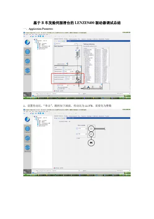
基于B车发舱伺服滑台的LENZE9400驱动器调试总结一、Application Parmeters1、设置传动比,“单击”,跳转如下画面。
传动比为11.378,需要化为整数2、设置电机基本参数,“单击”跳转如下画面1)、根据电机类型,选择电机类型。
此处选择伺服异步电机 2)、“单击”,设置电机参数,画面如下:123选择“From Driver ”,会自动获取电机基本参数 3) 、设置外围编码器的参数.“单击”,画面如下3.1)、编码器类型:此处选X8(绝对值编码器) 3.2)也选择绝对值编码213、根据齿轮大小,传动比。
设置相关参数。
“单击”,画面跳转如下1)、Feed constant: 传动轮转动一圈所走得距离。
本项目为527.1mm;根据齿轮数和齿间距可得出该值。
2)、Reference velocity: 计算所得的线速度。
可以设计的极限速度比较。
二者应该一样。
3)、Unit:选择单位mm4)、Motor reference speed :电机额定转速。
二、FB editor1 2 31、输入(控制字1W,定位模式速度值1W,速度模式速度值1W,目标位2W,定位模式加速度1W)以及一些常量1)、控制字。
PLC将控制字以整字的形式发给驱动器是,发的值是一一对应的,如发L#08,驱动器收到的就是L#08。
但是如果PLC将控制字以位的形式发给驱动器,则需要注意将高8位和低8位相反。
例如控制字PLC地址为QW40,则Q40.0对应驱动器bBit8,Q40.7对应bBit15;而Q41.0对应bBit0,Q41.7对应bBit7。
bBit0:SwitchOn 驱动器没有反馈Ready信号,则需要一直发此信号。
bBit1:预留bBit2:QSP 快停。
PLC发此信号,电机快速停止bBit3:速度模式正转bBit4:速度模式反转bBit5:预留bBit6:预留bBit7:故障复位(故障清楚)bBit8:预留 bBit9:预留 bBit10:预留bBit11:定位模式使能 ,走定位模式,必须发信号bBit12:定位模式启动 ,启动定位模式,在bBit11为真的前提下,电机开始运动。

9400 AWY Rel 2.1 Installation GuideHISTORICALEdition Date Comments Name01REFERENCE DOCUMENTS1 9400 AWY 2.1 Installation ManualTABLE OF CONTENTS1PURPOSE OF THIS DOCUMENT (5)2GLOSSARY (5)3PREPARATION FOR INDOOR INSTALLATION (6)3.1I NSTALLATION IN 42U L ABORACK (6)3.1.1Assemble the laborack (6)3.1.2Mount the laborack to the floor (6)3.1.3Ground the laborack (7)3.1.4Install the TRU into the rack (7)3.1.5Connect the TRU to the rectifier (8)3.1.6Ground the TRU (8)4INDOOR INSTALLATION (9)4.1G ENERAL PART (9)4.1.1Insert the flash card in the main IDU (9)4.1.2Mount the IDU into the rack (9)4.1.3Ground the IDU (11)4.1.4Connect the IDU power supply to the TRU (12)4.21+0 CONFIGURATION WITHOUT THE PATCH PANEL (13)4.2.1Connect the tributaries cables to the IDU (13)4.2.2Prepare the tributaries cables and connect them to the DDF (13)4.2.3Connect the housekeeping alarm cable (15)4.2.4Connect the NMS access cable (16)4.31+1 CONFIGURATION WITH PATCH PANEL (17)4.3.1Interconnect main and spare IDU together (17)4.3.2Assemble and install the patch panel (18)4.3.3Connect cables between the IDU and the patch panel (20)4.3.4Prepare the tributaries cables and connect them to the DDF (20)4.3.5Connect the housekeeping alarm cable (22)4.3.6Connect the NMS access cable (23)4.3.7Connect the User Service Channels cable (25)4.3.8Install the 3U DDF (26)5OUTDOOR INSTALLATION (27)5.1H OW TO COUPLE THE TRANSCEIVER (A-BOX) AND THE BRANCHING (D-BOX) BOXES IS CASE OF 7/8 G HZ ODU (27)5.2O UTDOOR INSTALLATION WITH INTEGRATED ANTENNA (28)5.2.1Mount the antenna on the pole mounting (28)5.2.2Outdoor system mounting : 1+0 case (28)5.2.3Outdoor system mounting : 1+1 HSB case (29)5.3O UTDOOR INSTALLATION WITH NON INTEGRATED ANTENNA (31)5.3.1Install the antenna on the structure (31)5.3.2Install the pole mounting on the sctructure (32)5.3.3Outdoor system mounting : 1+0 case (33)5.3.4Outdoor system mounting : 1+1 HSB case (35)6IDU-ODU CABLE INSTALLATION (38)6.1I NSTALL THE CABLE IN THE CABLE TRAY (38)6.2I NSTALL THE CABLE IN THE FEED THRU PLATE (39)6.3M OUNT THE N CONNECTORS ON THE CABLE (40)6.4C ONNECT THE CABLE TO THE IDU (41)6.5C ONNECT THE CABLE TO THE ODU (41)6.6G ROUND THE CABLE (43)7ANNEXES (45)7.1T OOLS DESCRIPTION (45)7.2T ELEPHONE HANDSET INSTALLATION (45)7.3H OW TO CHANGE THE POLARIZATION (46)7.3.113-38 GHz coupler (46)7.3.27/8 GHz coupler (47)7.3.3Integrated antenna (48)1 PURPOSE OF THIS DOCUMENTThis document is a complement to the installation manual and does not replace it. The main objective of this document is to facilitate the 9400 AWY installation procedure by tackling each step one by one, with the maximum visual help.The reader must have a good understanding of the microwave installation and a first experience in this field. 2 GLOSSARYDDF Digital Distributor FrameGND GroundIDU Indoor UnitNMS Network Management SystemODU Outdoor UnitRx ReceptionTRU Top Rack UnitTx Emission3 PREPARATION FOR INDOOR INSTALLATION 3.1 Installation in 42U Laborack3.1.1Assemble the laborack3.1.2 Mount the laborack to the floor3.1.3 Ground the laborack3.1.4 Install the TRU into the rackINSTALL THE TRU ONTOP OF THE RACKFix this cable to the groundof the room3.1.5 Connect the TRU to the rectifier4 INDOOR INSTALLATION4.1 Common part4.1.1 Insert the flash card in the main IDUMINIMUM DISTANCES BETWEEN SYSTEMS INSTALLED IN THE RACK FOR 1+0 SYSTEM4.1.3 Ground the IDU4.1.4 Connect the IDU power supply to the TRUCable labeling:In case of 1+1 configurationPOSITIVENEGATIVEGROUNDYellow/green cableBlue cableBrown cable4.2 1+0 configuration without the patch panel 4.2.1 Connect the tributaries cables to the IDUCable reference: 3CC52117AAAACable labeling:Mating cable wire pairs:P1P2 P3P4P5P6P7 P8whitebluewhite orange white greenWhitebrownWhitegreyyellowblueyellow orange Yellowgreen4.2.2.2 Tx 9 to 16Cable labeling:Mating cable wire pairs:P9P10P11P12 P13P14P15P16yellow brown Yellow GreyVioletBlueViolet Orange VioletGreenVioletBrownVioletGreyBlackblue4.2.2.3 Rx 1 to 8Cable labeling:Mating cable wire pairs:P1P2 P3P4P5P6P7P8whitebluewhite orange white greenWhitebrownWhitegreyyellowblueyellow orange YellowgreenCable labeling:Mating cable wire pairs:P9 P10 P11 P12 P13 P14 P15 P16 yellow brown Yellow Grey Violet Blue Violet Orange Violet Green Violet Brown Violet Grey Black blue4.2.3 Connect the housekeeping alarm cableCable reference: 3CC52115AAAACable labeling:Mating cable wire pairs:P6P5P14P15P21P7P8P16P22HK_O1COMA_1HK_O2HK_O3A_2COM_GNDHk_O4A_3COM_GNDHK_I1HK_I2HK_I4COM_GNDHK_I3HK_I5HK_I6redbluewhitegreyblackbrownblackgreyWhite/blueblueredorangeredgreenyellowblueWhite/blueorange4.2.4 Connect the NMS access cableCable reference: 3CC52115AAAA Cable labeling:Mating cable wire pairs:PAIR 5 : white/greyPAIR 6 : red/blueNMS G703 P17 P10 P11 P18 P2 P3V11_64K_DATA TX + V11_64K_DATA TX - V11_64K_DATA RX + V11_64K_DATA RX - V11_64K_CLOCK_CK+ V11_64K_CLOCK_CK- V11_64K_CLOCK_TCK+ V11_64K_CLOCK_TCK- G703_64K_TX+ G703_64K_TX- G703_64K_RX+ G703_64K_RX-Yellow orange red grey black blue yellow green white orange white green 4.3 1+1 configuration with patch panel4.3.1 Interconnect main and spare IDU together4.3.2 Assemble and install the patch panel4.3.3 Connect cables between the IDU and the patch panel4.3.4 Prepare the tributaries cables and connect them to the DDF Cable reference: 3DB06371AAAAThe number correspond to thepair numberPair 1 to 8 ↔ Tx 1 to Tx 8Pair 9 to 16 ↔ Rx 1 to Rx 8Each pair are pink/blueDon’t bend to muchthese cables4.3.4.1 Tx 1 to 8Cable labeling:Mating cable wire pairs:P1P2P3P4P5P6P7P8pink blue pink blue pink blue pink blue pink blue pink blue pink blue pink blue4.3.4.2 Rx 1 to 8Cable labeling:Mating cable wire pairs:P9P10P11P12P13P14P15P16pink blue pink blue pink blue pink blue pink blue pink blue pink blue pink blue4.3.5 Connect the housekeeping alarm cableCable reference: 3DB05594AAAAHOUSEKEEPING ALARMCable labeling:Mating cable wire pairs:P1 P2 P3 P4 P5 P6 P7 P8 A_2 COM A_3 GND HK_O1 A_1 HK_O3 HK_O4 HK_I1 HK_I2 HK_I3 HK_I4 HK_I5 HK_I6 HK_O2blue white purple turquoiseorange white purpleturquoisegreen white purpleturquoisebrown white purpleturquoise4.3.6 Connect the NMS access cableCable reference: 3DB05922AAAA (L=1,6m) or 3DB05923AAAA (L=6,4m)Cable labeling:4.3.7 Connect the User Service Channels cableCable reference: 3DB05994AAAACable labeling:Extra Service Channel4.3.8 Install the 3U DDF75 Ω DDF support120 Ω DDF support5 OUTDOOR INSTALLATION5.1 How to couple the transceiver (A-box) and the branching (D-box)boxes is case of 7/8 Ghz ODU(A) BRANCHING box label information(B) (HIGH FREQ) and (C) (LOW FREQ) RF interfaces on BRANCHING box(D) (TX) and (E) (RX) RF interfaces on TRANSCEIVER box5.2 Outdoor installation with integrated antenna 5.2.1 Mount the antenna on the pole mounting5.2.2.2 Ground the system5.2.3Outdoor system mounting: 1+1 HSB case5.2.3.1Mount the coupler on the pole mounting5.2.3.2 Mount the main and spare ODU on the coupler13 to 38 GHzMain ODUSpare ODU7/8 GHz5.2.3.3 Ground the system5.3 Outdoor installation with non integrated antenna5.3.1 Install the antenna on the structureSee antenna installation instructionsConnect the grounding cable from the coupler to the nearestgrounding plate5.3.2 Install the pole mounting on the structure5.3.3 Outdoor system mounting: 1+0 case5.3.3.1 Mount the ODU on the pole mountingNose adaptaterSilicone grease 7/8 GHz13 to 38 GHz5.3.3.2 Ground the systemConnect to the nearest groundingplate5.3.4 Outdoor system mounting: 1+1 HSB case 5.3.4.1Mount the coupler on the pole mounting7/8 GHz13 to 38 GHz5.3.4.2 Mount the main and spare ODU on the coupler5.3.4.3 Ground the system6 IDU-ODU CABLE INSTALLATION6.1 Install the cable in the cable trayTightenthetie raps in cross form6.2 Install the cable in the feed thru plate6.3 Mount the N connectors on the cableN connector with clamping nut TYPE 1AB095530021: 08-250-173 (IFM 422).STEP BY STEP PROCEDUREDESCRIPTIONS SKETCH 1-Strip the cable2- Put the clamping nut on the cable3- fold back the 10mm of braid on the jacket4- strip foil and dielectric5-Crimp the central contact (against the dielectric) on theinner conducteur. Crimping tool M22520/5-01 equippedwith normalized crimping inserts M22520/5-08.6-Mount the coupling part between the foil and the braidof the cable7-Flange the braid to the front of connector, then with acutting tool, cut the braid surplus close to the connector8-Mount the clamping nut and the coupling part by holdingthe body. Press with end wrenches the clamping nut.Note: coupling torque from 15Nm to 35 Nm maximum6.4 Connect the cable to the IDUThe tightening torque of the N connector is 3 Newton/mMain cableSpare cableIDU-ODU cableCable labeling:Connector waterproofing:Surround the connector with the auto amalgamate tape from up to downSurround the connector with the adhesive tape from up to downPut tie raps on the up and the down of the connector6.6 Ground the cableUse the Blue label spacinggrounding kit connection to7 ANNEXES7.1 Tools description7.2 Telephone handset installationconnector to the7.3 How to change the polarization7.3.1 13-38 GHz couplerThe axial adaptation between H polarization to V polarization (and vice versa) is a mechanical/electrical adjustment. Every mechanical “STEP” is 30° adjustment.1st Step: Rotate 30° the internal circle2nd Step: Rotate 60° the external circle7.3.2 7/8 GHz couplerVertical Polarization to Horizontal PolarizationThe point of reference is on the position V (vertical Polarization) to change the polarization needs to perform the following operations:1. Unscrew the three screws2. Turn the thin twist and to make to coincide the position H to the point of reference "Á."3. Screw the screwsHorizontal Polarization to Vertical PolarizationThe point of reference is on the position H (horizontal Polarization) to change the polarization needs to perform the following operations:1. Unscrew the three screws2. Turn the thin twist and to make to coincide the position V to the point of reference "A"3. Screw the screws7.3.3 Integrated antennaEND OF DOCUMENT。