伦茨lenze+SMD操作手册
- 格式:pdf
- 大小:3.76 MB
- 文档页数:24
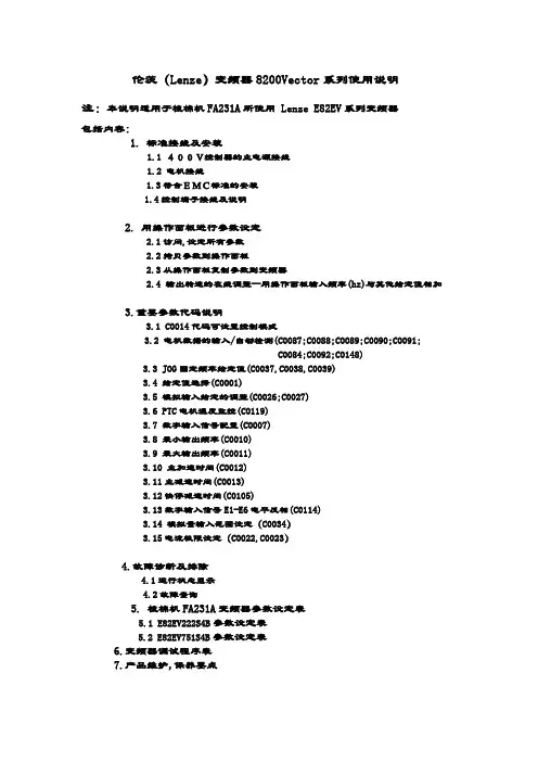
伦茨(Lenze)变频器8200Vector系列使用说明注:本说明适用于梳棉机FA231A所使用 Lenze E82EV系列变频器包括内容:1.标准接线及安装1.1 400V控制器的主电源接线1.2 电机接线1.3符合EMC标准的安装1.4控制端子接线及说明2. 用操作面板进行参数设定2.1访问,设定所有参数2.2拷贝参数到操作面板2.3从操作面板复制参数到变频器2.4 输出转速的在线调整--用操作面板输入频率(hz)与其他给定值相加3.重要参数代码说明3.1 C0014代码可设置控制模式3.2 电机数据的输入/自动检测(C0087;C0088;C0089;C0090;C0091;C0084;C0092;C0148)3.3 JOG固定频率给定值(C0037,C0038,C0039)3.4 给定值选择(C0001)3.5 模拟输入给定的调整(C0026;C0027)3.6 PTC电机温度监控(C0119)3.7 数字输入信号配置(C0007)3.8 最小输出频率(C0010)3.9 最大输出频率(C0011)3.10 主加速时间(C0012)3.11主减速时间(C0013)3.12快停减速时间(C0105)3.13数字输入信号E1-E6电平反相(C0114)3.14 模拟量输入范围设定(C0034)3.15电流极限设定(C0022,C0023)4.故障诊断及排除4.1运行状态显示4.2故障查询5. 梳棉机FA231A变频器参数设定表5.1 E82EV222S4B参数设定表5.2 E82EV751S4B参数设定表6.变频器调试程序表7.产品维护,保养要点1.标准接线及安装1.1 400V控制器的主电源接线1.2 电机接线见上图注:BR1,BR2外部制动电阻T1,T21.3符合EMC标准的安装使用低寄生电容电缆。
每单位长度电容值:●芯/芯≤75pF/m●芯/屏蔽层≤150pF/mEMC电缆密封垫按铭牌进行电机接线使用表面导电的安装板以尽可能大的导电表面将电缆屏蔽层连到PE上。
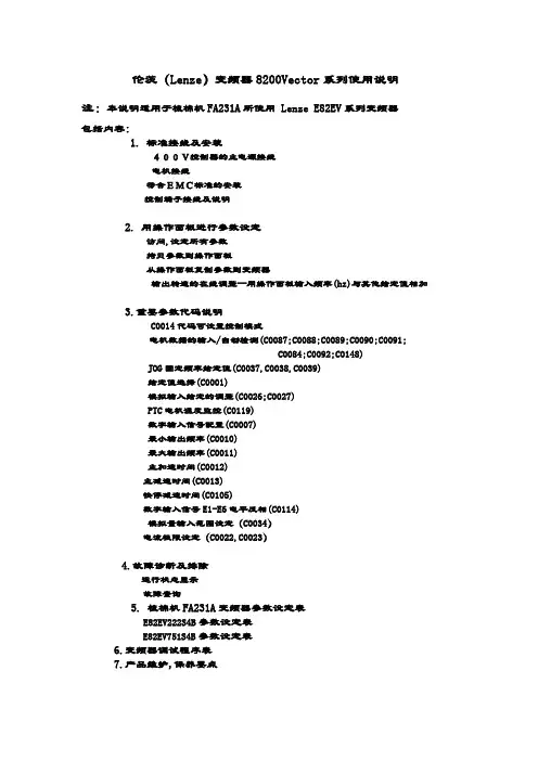
伦茨(Lenze)变频器8200Vector系列使用说明注:本说明适用于梳棉机FA231A所使用 Lenze E82EV系列变频器包括内容:1.标准接线及安装400V控制器的主电源接线电机接线符合EMC标准的安装控制端子接线及说明2. 用操作面板进行参数设定访问,设定所有参数拷贝参数到操作面板从操作面板复制参数到变频器输出转速的在线调整--用操作面板输入频率(hz)与其他给定值相加3.重要参数代码说明C0014代码可设置控制模式电机数据的输入/自动检测(C0087;C0088;C0089;C0090;C0091;C0084;C0092;C0148)JOG固定频率给定值(C0037,C0038,C0039)给定值选择(C0001)模拟输入给定的调整(C0026;C0027)PTC电机温度监控(C0119)数字输入信号配置(C0007)最小输出频率(C0010)最大输出频率(C0011)主加速时间(C0012)主减速时间(C0013)快停减速时间(C0105)数字输入信号E1-E6电平反相(C0114)模拟量输入范围设定(C0034)电流极限设定(C0022,C0023)4.故障诊断及排除运行状态显示故障查询5. 梳棉机FA231A变频器参数设定表E82EV222S4B参数设定表E82EV751S4B参数设定表6.变频器调试程序表7.产品维护,保养要点1.标准接线及安装400V控制器的主电源接线电机接线见上图注:BR1,BR2外部制动电阻T1,T2电机温度监控PTC热敏电阻或热继电器符合EMC标准的安装注:将控制线及电源线与电机电缆分开使用低寄生电容电缆。
每单位长度电容值:●芯/芯≤75pF/m●芯/屏蔽层≤150pF/mEMC电缆密封垫按铭牌进行电机接线使用表面导电的安装板以尽可能大的导电表面将电缆屏蔽层连到PE上。
使用Lenze提供的固定支架。
控制端子接线及说明注:●插上端子排前,先接好线!●仅可在控制器禁止时插拔端子排!●不用的端子排也应插上,以保护连接部件。


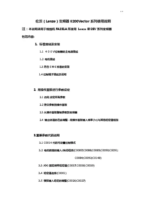
伦茨(Lenze)变频器8200Vector系列使用说明注:本说明适用于梳棉机FA231A所使用Lenze E82EV系列变频器包括内容:1.标准接线及安装1.1 400V控制器的主电源接线1.2 电机接线1.3符合EMC标准的安装1.4控制端子接线及说明2. 用操作面板进行参数设定2.1访问,设定所有参数2.2拷贝参数到操作面板2.3从操作面板复制参数到变频器2.4 输出转速的在线调整--用操作面板输入频率(hz)与其他给定值相加3.重要参数代码说明3.1 C0014代码可设置控制模式3.2 电机数据的输入/自动检测(C0087;C0088;C0089;C0090;C0091;C0084;C0092;C0148)3.3 JOG固定频率给定值(C0037,C0038,C0039)3.4 给定值选择(C0001)3.5 模拟输入给定的调整(C0026;C0027)3.6 PTC电机温度监控(C0119)3.7 数字输入信号配置(C0007)3.8 最小输出频率(C0010)3.9 最大输出频率(C0011)3.10 主加速时间(C0012)3.11主减速时间(C0013)3.12快停减速时间(C0105)3.13数字输入信号E1-E6电平反相(C0114)3.14 模拟量输入范围设定(C0034)3.15电流极限设定(C0022,C0023)4.故障诊断及排除4.1运行状态显示4.2故障查询5. 梳棉机FA231A变频器参数设定表5.1 E82EV222S4B参数设定表5.2 E82EV751S4B参数设定表6.变频器调试程序表7.产品维护,保养要点1.标准接线及安装1.1 400V控制器的主电源接线1.2 电机接线见上图注:BR1,BR2外部制动电阻T1,T2电机温度监控PTC热敏电阻或热继电器1.3符合EMC标准的安装注:将控制线及电源线与电机电缆分开使用低寄生电容电缆。
每单位长度电容值:●芯/芯≤75pF/m●芯/屏蔽层≤150pF/mEMC电缆密封垫按铭牌进行电机接线使用表面导电的安装板以尽可能大的导电表面将电缆屏蔽层连到PE上。
Getting Started with SMD &Modbus RTU CommunicationsOverviewModbus is an internationally accepted asynchronous serial protocol designed for commercial and industrial automation. Modbus RTU is an RS485 based master/slave system that can operate over a selected range of baud rates. It was Developed by Modicon for PLC communications, but today is also commonly used for basic parameter control on drives.All L variant SMD drives have an integrated RS485 serial communication port and can fully support communication from a Modbus RTU master device, such as a PC, HMI or PLC.Example part number of an L variant SMD drive:-ESMD371L2YXAScopeThis document is intended to provide a helpful getting started guide for configuring the Modbus RTU master to correctly communicate with a SMD drive and is aimed to accompany the “SMD Modbus RTU Operations Manual”.It is assumed that the user has familiarised themselves with how to navigate through the drive parameters using the keypad. Refer to the drive user manual for details. Methods for configuring master devices can differ greatly between manufacturers, therefore details for configuring a specific network master are NOT provided herein. However, a very basic generic guide is provided.Serial Port ParametersFor devices that communicate on a Modbus serial network using the RTU (Remote Terminal Unit) mode, it is possible to configure the master and slave serial ports in several different ways. In order for communication to work correctly all devices on the network must be configured the same, i.e.• Baud rate• Start bits• Data size• Parity• Stop bitsDrive ConfigurationSet the following drive parameters:-• C01 - Control Source: Must be set to a value of 8 to 11 (see the drive Operating Instructions for full details).• c25 - Baud Rate: This parameter actually configures more than just the drive baud rat, it also configures all of the serial parameters as described above. (see the drive Operating Instructions for full details).• n22 and n23 - Serial Fault and time out: see the drive Operating Instructions for full details).Modbus frame structureThe message structure for a Modbus message is as follows:-Address: • Size = 1 byte • Valid slave nodes addresses are in the range of 0 – 247 decimal, however,address 0 is reserved for use as a broadcast address. • The individual slave devices are assigned addresses in the range of 1 – 247,each slave node on the network must have an individual address, if two of more nodes have duplicate addresses this may prevent the network from functioning correctly. • A master addresses a slave by placing the slave address in the address field ofthe message. When the slave returns its response, it places its own address in the response address field to let the master know which slave is responding. Function Code • Size = 1 byte • The function code indicates what kind of action to perform. • The function code (depending upon the function) is normally followed by a datafield that contains request and response parameters. • The SMD supports function codes:-• 3 - Read Holding Registers* • 4 - Read Input Registers • 6 - Preset Single Register • 16 - Preset Multiple Registers** - Note: In general the SMD is limited in that it will only support Read and Write access to one register at a time. See the SMD Modbus Control Operation Manual section 2 for details and exceptions. Data • Master frame size = 4 bytes• 2 bytes for register number • 2 bytes for either number of register to read, or data to be written • Slave frame size = 3 or 4 bytes• 3 bytes for read response; data size in byte followed by the actual data(there is an exception to this which is detailed in the “SMD Modbus RTU Operations Manual”). • 4 bytes for a write response; which is a repeat of the original master datathat was written.Error Check • The Error checking field is the result of a "Cyclical Redundancy Checking" (CRC)calculation that is performed on the message contents. • For full details on how to calculate the CRC please refer to the official ModbusRTU specification.Modbus Registers• The “SMD Modbus Control Operation Manual” provides a complete list of many of which have a direct relationship to actual drive parameters.•For every drive parameter there is a corresponding Modbus register. However, in addition to these there also several additional registers that are only accessible through Modbus. All of these registers are detailed in the “SMD Modbus Control Operation Manual”.•To help clarify the statement in “SMD Modbus Control Operation Manual” section “2C”: Due to the way in which most Modbus masters typically access slave registers it may be necessary to add “1” to the SMD register number to ensure access to the correct register because the master automatically deducts “1” from the register number, e.g.C37 - Fixed setpoint1 is listed as register address 74 (for SMD PV507). To correctly access this address, the master actually needs to use register 40075, thereafter the master automatically deducts “1” during its message frame construction and will therefore really access drive register 40074. •Some Modbus Master devices have the option to use zero base addressing; de-selecting this will simply everything as all registers will then have the correct off-set, i.e. 1 to 1 register addressing.Drive Security• For read access no security has to be set as read only access is always granted (while C01 = 8 - 11).•Assuming that the drive password has not been activated, (see C94), writing a value of “0” to drive register 48 (40048) will unlock both drive control and parameter access.•If a password has been configured, then writing the password number to drive register 48 will again unlock access to both areas.Writing only “0” to drive register 48 after a password has been configured will then only unlock access to the drive control registers.• Parameter access can be unlocked independently by writing “0” to drive register 49•To re-activate / re-secure access to these areas simply set BIT-1 of the drive control register 1.ExamplesExample 1 - Reading Fixed Setpoint 1 (C37 default value of 20)Modbus Master request frame transmissionModbus Slave response frame transmissionExample 2 - Writing to a value of 12.3Hz to Fixed Setpoint 1 (C37)Modbus Master request frame transmissionModbus Slave response frame transmissionExample 3 - unlock security, enable drive and control the motor speedThe following drive parameters are assumed to have been already set:- • C01 = 11 (default value is 0) • C09 = 1 as per default • C94 = 0 as per default • Close terminal 20 and 281. Unlocking security, set a value of 0 to drive register 48Modbus Master frame transmission2. Set BIT-8 of the Control Word to select “Serial Speed Reference” Modbus Master frame transmission3.Set BIT-3 of the Control Word to enable the drive, the drive display will change Modbus Master frame transmission4.Set a value of 250 to the serial speed reference register 40. The drive display will change to display the output frequency which will be 25.0Hz. Modbus Master frame transmission5.Set BIT-2 of the Control Word to disable the drive, the drive display will change to “Inh” for inhibitModbus Master frame transmission。

782031C N Lenze伦茨橾作手册Global Drive8200/8210系列变频器功率范围0.37…11KW怎样用这些操作指令…对特定的功能,可先参考表中的内容,然后根据索引可看到详细的操作说明为了查阅方便操作指南中用了不同的符号,并在重要的条款中做了加黑处理这个符号给出方便操作信息注意!尽可能避免损坏设备注意!操作时小心人身安全Lenze 1本技术说明用于带有以下名牌的设备8201 E.lx.lx 8203 E.lx.lx 8211 E.Ox.lx 8213 E.Ox.lx 8202 E.lx.lx 8204 E.lx.lx 82l2 E.Ox.lx 82l4 E.0x.lx82l5 E.Ox.lx 82l7 E.Ox.lx 82ll E.lx.2x 82l3 E.lx.2x 82l5 E.lx.2x 82l7 E.lx.2x 82O2E.lx.lx.YOO282l6 E.Ox.lx82l8 E.Ox.lx82l2 E.lx.2x82l4 E.lx.2x82l6 E.lx.2x82l8 E.lx.2x82O2 E.2x.lx.YOO2 装配深度减少的改型变频器类型IP2O封装硬件版本号和索引号软件版本和索引号改型编辑:O3.ll.l994 打印日期 O5.l2.l994 改变软件版本号2x 13.02.199507.08.19952 Lenze目录设计和安装8200/8210系列的特点 (6)1.变频器的数据 (7)1.1通用数据 (7)1.2与型号有关的数据 (8)1.3制造商声明 (9)1.3.1直接应用 (9)2.尺寸和安装 (10)2.1安装 (10)2.2外型尺寸 (11)3.01 (14)3.18200系列变频器的主电路连接 (14)3.28210系列的主电路连接 (15)3.3控制接线 (16)3.4控制输入和输出 (17)3.5并联直流母线运行 (18)3.5.1多台变频器的并联 (18)3.5.2直流电压供电 (18)3.6射频干扰的抑制和屏蔽 (19)4.23 (21)4.1操作面板8201BB (21)4.2操作面板的引出端子的8272BB (22)4.3设定电位器 (23)4.4制动斩波器 (23)4.5主电抗器 (25)4.6熔断器 (26)4.7抑制射频干扰滤波器 (27)4.8电机滤波器 (28)4.9电机电压滤波器 (29)4.10附件 (30)编程:1.开关初始化 (31)2 (32)3.显示 (34)3.1运行状态显示 (34)3.2操作面板8201BB (34)3.3显示值 (36)3.4启动显示 (36)4.基本控制操作 (37)4.1操作编程结构 (37)Lenze 34.2参数代码的设定和改变 (37)4.3操作模式 (40)4.4参数集 (40)5.8200变频器的编程 (41)5.1基本设定 (41)5.1.1最小输出频率f mn (41)5.1.2最大频率设定f_ (41)5.1.3加、减速时间设定 (42)5.1.4V/f 额定频率 (42)5.1.5V/f特性和提升电压设定V_ (43)5.2给定值选择 (44)5.2.1模拟量给定值选择 (44)5.2.2通过LCD操作面板给定 (44)5.2.3寸动频率JOG (45)5.2.4模拟电机电位器 (45)5.3UVWXYZ (46)5.3.1控制器使能(RFR) (46)5.3.2改变旋转方向(CW/CCW) (46)5.3.3快速停止(QSP) (47)5.3.4DC 制动(DC INJ) (47)5.3.5改变参数集(PAR) (47)5.3.6跳闸设定(TRIP) (48)5.3.7端子配置一览 (48)5.3.8继电器输出 (49)5.3.9模拟量输出 (50)5.4扩展设置 (51)5.4.1起动选择/瞬间重起动电路 (51)5.4.2最大电流限制 (52)5.4.3I2.t 监视 (53)5.4.4滑差补偿 (53)5.4.5跳闸复位 (54)5.4.6运行时间表 (54)5.4.7软件版本和变频器型号 (54)5.58200系列代码表 (59)6.8210系列变频器编程 (59)6.1基本设置 (59)6.1.1最小输出频率f;^ (59)6.1.2最大输出频率fj/4 (60)6.1.3加速和减速时间 (61)6.1.4V/f额定频率t (62)6.1.5控制方式 (62)6.1.6提升电压V/i n设定 (62)6.2设定值选择 (62)6.2.1模拟量给定值选择 (63)6.2.2通过操作面板给定 (64)4Lenze6.2.3寸动频率(JOG) (64)6.2.4电机电位器 (64)6.3控制端子功能 (65)6.3.1控制器使能(RFR) (65)6.3.2改变旋转方向(CW/CCW) (66)6.3.3快停(QSP) (66)6.3.4直流制动(DC INJ) (66)6.3.5参数集(TRIP)改变 (67)6.3.6跳闸设定 (68)6.3.7端子配置一览 (69)6.3.8继电器输出 (70)6.3.9模拟量输出 (70)6.4扩展设定 (71)6.4.1起动选择/瞬间重起动 (72)6.4.)最大电流限制 (72)6.4.3电机数据输人 (73)6.4.4I2.t 监控 (73)6.4.5滑差补偿 (74)6.4.6斩波频率 (74)6.4.7跳闸复位 (74)6.4.8运行时间表 (74)6.4.9软件版本和变频器型号 (75)6.4.10运行速度显示 (75)6.58210系列代码表 (76)维护1.监视报警 (81)2.故障报警 (81)2.1主电路连接中错误指示 (81)2.2操作中的故障报警 (81)3.故障确定 (83)3.1电机不转 (83)3.2LED绿灯闪烁 (83)3.3LED红灯闪烁(每0.4秒) (83)3.4LED红灯闪烁(每秒) (83)3.5LED 不亮 (83)3.6电机运行不平稳 (83)3.7电机的电流过大 (84)Lenze 58200/8210系列的特点230V电压等级的8200系列包括4种型号的变频器。

782031C N Lenze伦茨橾作手册Global Drive8200/8210系列变频器功率范围0.37…11KW怎样用这些操作指令…对特定的功能,可先参考表中的内容,然后根据索引可看到详细的操作说明为了查阅方便操作指南中用了不同的符号,并在重要的条款中做了加黑处理这个符号给出方便操作信息注意!尽可能避免损坏设备注意!操作时小心人身安全Lenze 1本技术说明用于带有以下名牌的设备8201 E.lx.lx 8203 E.lx.lx 8211 E.Ox.lx 8213 E.Ox.lx 8202 E.lx.lx 8204 E.lx.lx 82l2 E.Ox.lx 82l4 E.0x.lx82l5 E.Ox.lx 82l7 E.Ox.lx 82ll E.lx.2x 82l3 E.lx.2x 82l5 E.lx.2x 82l7 E.lx.2x 82O2E.lx.lx.YOO282l6 E.Ox.lx82l8 E.Ox.lx82l2 E.lx.2x82l4 E.lx.2x82l6 E.lx.2x82l8 E.lx.2x82O2 E.2x.lx.YOO2 装配深度减少的改型变频器类型IP2O封装硬件版本号和索引号软件版本和索引号改型编辑:O3.ll.l994 打印日期 O5.l2.l994 改变软件版本号2x 13.02.199507.08.19952 Lenze目录设计和安装8200/8210系列的特点 (6)1.变频器的数据 (7)1.1通用数据 (7)1.2与型号有关的数据 (8)1.3制造商声明 (9)1.3.1直接应用 (9)2.尺寸和安装 (10)2.1安装 (10)2.2外型尺寸 (11)3.01 (14)3.18200系列变频器的主电路连接 (14)3.28210系列的主电路连接 (15)3.3控制接线 (16)3.4控制输入和输出 (17)3.5并联直流母线运行 (18)3.5.1多台变频器的并联 (18)3.5.2直流电压供电 (18)3.6射频干扰的抑制和屏蔽 (19)4.23 (21)4.1操作面板8201BB (21)4.2操作面板的引出端子的8272BB (22)4.3设定电位器 (23)4.4制动斩波器 (23)4.5主电抗器 (25)4.6熔断器 (26)4.7抑制射频干扰滤波器 (27)4.8电机滤波器 (28)4.9电机电压滤波器 (29)4.10附件 (30)编程:1.开关初始化 (31)2 (32)3.显示 (34)3.1运行状态显示 (34)3.2操作面板8201BB (34)3.3显示值 (36)3.4启动显示 (36)4.基本控制操作 (37)4.1操作编程结构 (37)Lenze 34.2参数代码的设定和改变 (37)4.3操作模式 (40)4.4参数集 (40)5.8200变频器的编程 (41)5.1基本设定 (41)5.1.1最小输出频率f mn (41)5.1.2最大频率设定f_ (41)5.1.3加、减速时间设定 (42)5.1.4V/f 额定频率 (42)5.1.5V/f特性和提升电压设定V_ (43)5.2给定值选择 (44)5.2.1模拟量给定值选择 (44)5.2.2通过LCD操作面板给定 (44)5.2.3寸动频率JOG (45)5.2.4模拟电机电位器 (45)5.3UVWXYZ (46)5.3.1控制器使能(RFR) (46)5.3.2改变旋转方向(CW/CCW) (46)5.3.3快速停止(QSP) (47)5.3.4DC 制动(DC INJ) (47)5.3.5改变参数集(PAR) (47)5.3.6跳闸设定(TRIP) (48)5.3.7端子配置一览 (48)5.3.8继电器输出 (49)5.3.9模拟量输出 (50)5.4扩展设置 (51)5.4.1起动选择/瞬间重起动电路 (51)5.4.2最大电流限制 (52)5.4.3I2.t 监视 (53)5.4.4滑差补偿 (53)5.4.5跳闸复位 (54)5.4.6运行时间表 (54)5.4.7软件版本和变频器型号 (54)5.58200系列代码表 (59)6.8210系列变频器编程 (59)6.1基本设置 (59)6.1.1最小输出频率f;^ (59)6.1.2最大输出频率fj/4 (60)6.1.3加速和减速时间 (61)6.1.4V/f额定频率t (62)6.1.5控制方式 (62)6.1.6提升电压V/i n设定 (62)6.2设定值选择 (62)6.2.1模拟量给定值选择 (63)6.2.2通过操作面板给定 (64)4Lenze6.2.3寸动频率(JOG) (64)6.2.4电机电位器 (64)6.3控制端子功能 (65)6.3.1控制器使能(RFR) (65)6.3.2改变旋转方向(CW/CCW) (66)6.3.3快停(QSP) (66)6.3.4直流制动(DC INJ) (66)6.3.5参数集(TRIP)改变 (67)6.3.6跳闸设定 (68)6.3.7端子配置一览 (69)6.3.8继电器输出 (70)6.3.9模拟量输出 (70)6.4扩展设定 (71)6.4.1起动选择/瞬间重起动 (72)6.4.)最大电流限制 (72)6.4.3电机数据输人 (73)6.4.4I2.t 监控 (73)6.4.5滑差补偿 (74)6.4.6斩波频率 (74)6.4.7跳闸复位 (74)6.4.8运行时间表 (74)6.4.9软件版本和变频器型号 (75)6.4.10运行速度显示 (75)6.58210系列代码表 (76)维护1.监视报警 (81)2.故障报警 (81)2.1主电路连接中错误指示 (81)2.2操作中的故障报警 (81)3.故障确定 (83)3.1电机不转 (83)3.2LED绿灯闪烁 (83)3.3LED红灯闪烁(每0.4秒) (83)3.4LED红灯闪烁(每秒) (83)3.5LED 不亮 (83)3.6电机运行不平稳 (83)3.7电机的电流过大 (84)Lenze 58200/8210系列的特点230V电压等级的8200系列包括4种型号的变频器。
伦茨制动暂波器说明书一、产品概述二、产品结构三、产品原理当电磁铁通电时,产生的磁力使制动摩擦片与制动盘结合,从而产生制动扭矩,使被控制的设备或传动系统停止或减速。
当电磁铁断电时,磁力消失,制动摩擦片与制动盘分离,设备或传动系统恢复正常运行。
四、产品特点1.结构简单:伦茨制动暂波器采用简单的结构设计,易于安装和维修。
2.操作方便:通过电源控制电磁铁的通断,实现设备的停止或减速。
3.性能稳定:制动盘和制动摩擦片采用优质材料,具有较高的耐磨性和稳定的性能。
4.扭矩可调:通过调节制动摩擦片的压力或电磁铁的电流,可以调整制动暂波器的制动扭矩。
五、产品使用注意事项1.在安装和使用伦茨制动暂波器时,应遵循相关的安全操作规程和使用说明。
2.避免超载:在使用过程中,应严格控制设备或传动系统的负载,避免超过制动暂波器的承载能力。
3.定期检查和维护:定期检查制动盘和制动摩擦片的磨损情况,并及时更换,以保证整个系统的性能。
4.避免过热:长时间连续使用制动暂波器可能会导致过热,需注意散热措施。
5.防止外界物质进入:保持制动盘和制动摩擦片的清洁,防止进入杂物对其运行造成干扰。
六、产品维护与保养1.定期检查电磁铁的连接线是否松动,若松动应及时固定或更换。
2.定期清洁制动盘和摩擦片表面,避免杂物进入及增加制动摩擦片的磨损。
3.定期检查和更换磨损较大的制动摩擦片,保证其制动性能。
七、常见故障及解决方法1.刹车效果差:检查制动盘和制动摩擦片是否磨损,如磨损严重,需要更换新的制动摩擦片。
2.制动盘过热:检查散热措施是否有效,如有必要,可增加散热器或更换具有更好散热性能的材料。
3.电磁铁无法正常工作:检查电源是否正常供电,电磁铁与控制装置的连接是否良好。
伦茨制动暂波器说明书第一部分:产品介绍伦茨制动暂波器是一种先进的制动装置,主要用于汽车、火车等运输工具的制动控制。
它采用了伦茨原理,通过调节电流和电磁力来实现制动效果,并能够在制动过程中产生暂波用于能量回收。
该装置具有制动力强、调节灵活、能量回收等优点,是现代交通工具中不可或缺的部件之一第二部分:工作原理伦茨制动暂波器主要由磁铁、线圈和电子控制板组成。
当驾驶员踩下制动踏板时,电信号通过电子控制板传输到线圈,激活磁铁。
磁铁的强磁场会产生电磁力,这种力会使制动器与制动盘之间产生摩擦,从而产生制动力。
同时,线圈会随着电流的变化产生暂波,并通过电子控制板将暂波回收到电池中以供以后使用。
第三部分:使用方法1.安装:将制动暂波器正确安装在交通工具上,确保线圈与制动盘紧密接触,以确保制动效果良好。
2.接线:根据产品说明书上的接线图,正确连接制动暂波器的电源和线圈接口。
3.调节:根据实际需要,通过调节电子控制板上的参数来实现制动力的调节。
调节时需注意不要将制动力调得过大,以免造成制动器和制动盘的磨损过快。
4.维护:定期检查制动暂波器的线路和电接触点是否正常。
如发现有损坏或松动的地方,及时进行修复或更换。
第四部分:注意事项1.请勿在人群密集的地方进行制动暂波器的测试和使用,以免造成伤害。
2.请确保制动暂波器的电源连接时正确的,以免损坏线圈和电子控制板。
4.请勿私自拆卸制动暂波器的内部零件,以免影响正常工作。
5.当不使用制动暂波器时,请将其关闭并断开电源。
第五部分:售后服务结束语伦茨制动暂波器是高效、安全的制动装置,它的使用不仅可以有效提升制动效果,还可以回收能量,减少能源消耗。
我们相信,在您正确使用和维护的情况下,伦茨制动暂波器将为您的交通工具带来更好的性能和舒适的驾驶体验。
感谢您选择伦茨制动暂波器,祝您驾驶愉快!。