吉普JEEP大切诺基安装博文BOWON泊车前后可视
- 格式:pdf
- 大小:631.30 KB
- 文档页数:7
INSTALLATION INSTRUCTIONSJeep Wrangler JK Quad-camera with DVR SystemSMTV-2421Items Included in the KitUnderhood power/video harnessWinch mount with attached camera2 Underhood power/video harness2 Front bumper mount with attached camera 2 Mounting bracket4 Allen screws for mounting bracket.1 Bottle of Z-tech3 Camera cut out templatesCameraChassis HarnessPower HarnessZip lock bag with 15 Wire Ties & 3 Push Nuts Camera Extension Bracket22--pin white connector w/ video RCA7” DVR Monitor4GB SD CardMonitor Power Harness Required Tools & SuppliesT15 & T20 Torx Bits7mm & 10mm SocketsPhillips Screwdriver3/8” Wrench or Socket DrivePlastic Trim Removal ToolSoldering Iron, Solder, & Heat Shrink Tubing (RECOMMENDED)Electrical Tape1 3/8 “ Hole SawPlease read so you do not V OIDthewarranty:If the camera harness is run through the center on the camera bracket, it will cut the camera harness. This will void the warranty on the camera.INSTALLATION INSTRUCTIONSInstall CameraStep 1: Loosen lug nuts to remove spare tire.Step 2: Slide Camera on studs placing harness endinside of tire carrier. D o not run harness through the camera bracket opening.Step 3:Adjust Camera head to fit your specific wheel. Bracket is shipped in factory wheel configuration.INSTALLATION INSTRUCTIONSAdjustment Bracket for Camera Clearance using Phillips Screwdriver and 3/8” Wrench or Socket DriveNote: Short Bracket has been designed for Factory offset wheels. Use the Long Bracket for wheels with larger offsets.Step 4: Remove spare tire and slide (3) supplied PushNuts on the studs.Step 5: Reinstall spare tire.Install Chassis HarnessStep 6: Insert connector from Camera connector through the rear gate vent behind tire carrier.Step 7: Using a plastic trim removal tool, removeinterior panels on inside of rear gate.Step 8: Pull harness through the rear gate openings. Step 9: Use supplied Wire Ties to secure Chassis Harness to existing harness.Step 10: Use supplied Wire Ties to secure ChassisHarness to existing harness.Step 11: Use supplied Wire Ties to secure Chassis Harness to fabric factory wire cover. CAUTION: Leave enough slack to allow gate to open fully.Step 12: Use a T20 Torx bit to remove subwoofer box.Step 13:Using a plastic trim removal tool, pry off rear seat belt closeout.Step 14:Using a plastic trim removal tool, remove rear access panel to expose 10mm bolt, and remove bolt.Step 15: Pull out subwoofer box slightly to gain accessto run Chassis Harness along existing harness Step 16:Pull back carpet and continue running Chassis Harness forward.NOTE: This camera has parklines or non parklines Grid line options: Default setting is to display grid lines. To remove the grid line display, connect the two green wires near the end of the camera harness.Green and white wires on the camera harness.Wench Camera InstructionsMounting camera ABOVE the fairlead:1.Remove the fairlead from your front winch assembly and/or bumper.2.Position the front camera bracket so that its mounting holes line up with the mounting holes on your fairlead. Withthe camera over the top of the fairlead.3.Before the bolts go back into the fairlead and camera mounting plate, apply Z-tech to the bolts holes and anywhereon the back or side if any adjustments get made. (Later in install instructions.)4.Reattach the fairlead and front camera bracket to your front winch assembly and/or bumper with the camera ontop of fairlead.5.Plug in the water proof camera connector into the power harness. Make sure the connector is going the proper wayand that it plugs in all the way.6.Route the harness away from any moving parts so the harness will not get cut. Enter the underhood area andsecure to the harness running along the driver’s side fender with zip ties.7.Route the camera harness into the vehicle's interior through the factory grommet in the firewall on the driver’s side.8.Route the harness to the location of where the display will be.9.Connect the RED wire to 12 accessory power. Make sure to use a Digital MultiMeter to test for power.10.Connect the BLACK wire to a good clean ground.11.Plug the RCA end to the video display.Mounting camera BELOW the fairlead:y camera face down on a bench or table with something to protect the camera face. Remove the (4) 3mm Allenbolts on the side of the camera mount.2.Pull the bracket off the mount and rotate 180º and insert the Allen bolts back in, do not tighten all the way untilinstalled and adjusted.3.On the inside on the camera mount, loosen the (2) 2.5mm Allen screws to turn the front camera 180º. (There is asticker inside the camera housing, on top of the camera. The sticker marks the top/up side of the camera.)4.Tighten the (2) Allen screws back tight. Apply Z-tech to the back of the camera where the Allen screws are and onthe insides on the camera housing.5.Remove the fairlead from your front winch assembly and/or bumper.6.Position the front camera bracket so that its mounting holes line up with the mounting holes on your fairlead withthe camera over the top of the fairlead.7.Before the bolts go back into the fairlead and camera mounting plate, apply Z-tech to the bolts holes and anywhereon the back or side if any adjustments get made. (Later in install instructions.)8.Reattach the fairlead and front camera bracket to your front winch assembly and/or bumper with the camera ontop of fairlead.9.Plug in the water proof camera connector into the power harness. Make sure the connector is going the proper wayand that it plugs in all the way.Route the harness away from any moving parts so the harness will not get cut. Enter the underhood area and secure to the harness running along the driver’s side fender with zip ties.10.Route the camera harness into the vehicle's interior through the factory grommet in the firewall on the driver’s side.11.Route the harness to the location of where the display will be.12.Power and ground connections will be made after the monitor is installedMounting Camera WITHOUT Fairlead1.Remove the camera from the fairlead bracket. Remove the 2 small allen bolts from the back of the camera. Thesmall rectangular plate will come out of the back of the bracket and the camera will come right out.2.Keep the small rectangular piece and two allen bolts3.Determine desired mounting location and follow same steps from Rockcrawler camera installation instructions.CAMERA ADJUSTMENT:1.To adjust the camera angle up and down, loosen the (4) 3mm Allen bolts on the side of the camera mount to thebracket.2.There is 40º of angle up and down.3.As the camera angle changes, check the display to see if is the correct viewing area.4.Adjust the angle up or down and retighten the (4) Allen bolts.Rock Crawler Camera InstallationDo not c ut any holes until you find a placement that fits your needs!! 1.Determine the best location for the camera to be mounted to the vehicle. I t is recommended that theharnesses for the cameras be run to the location where connections will be made to the display so that you can determine the best location for the cameras. Then follow the mounting instructions. e the template to see if there is clearance to mount the camera flat to the bumper. (Located on thelast page of these instructions.)3.Make the center hole and drill a 1⅜” hole to mount the camera.4.Apply Z-tech to the exposed metal that was just drilled. (It is advised to paint the bare metal where thehole was just drilled.)5.Insert the camera mount into the hole with the camera top-side up. (The top/up of the camera has awhite sticker on the camera inside the mount.)6.From the back side of the camera mount, attach the mounting bracket with the (2) 2.5mm Allen screws.Do not tighten the screws all the way until the view can be checked.7.Plug in the water proof camera connector into the power harness. Make sure the connector is going theproper way and that it plugs in all the way.8.Route the harness away from any moving parts so the harness will not get cut. Enter the underhood areaand secure to the harness running along the driver’s side fender with zip ties.9.Repeat mounting for the second camera. (One can be placed at each far end of the front bumper.)10.Route the camera harness into the vehicle's interior through the factory grommet in the firewall on thedriver’s side.11.Route the harness to the location of where the display will be.12.Connect the RED wires from cameras to 12v accessory power. Make sure to use a Digital MultiMeter totest for power.13.Connect the BLACK wires from cameras to a good clean ground.14.Plug the RCA end to the video display.15.Check the viewing area or the display. If it’s correct, then tighten the (2) 2.5mm Allen screws.16.Apply Z-tech inside the mount on the Allen screws and bracket.Monitor Mounting/Use InstructionsVehicle Wiring: W hen wiring the kit on some applications there might not be access to some of the trigger wires. (Left, Right turn signals, Reverse, etc.) When trigger wires are not available use toggle switch to trigger input. Trigger wires are only needed for auto switching inputs. Can Manual switch video inputs on monitor. Monitor Mounting: R emove the factory rear view mirror. Using the D-tab adaptor included in the kit, mount the monitor on the adaptor before mounting on the windshield. You will need to loosen the six screws, pictured below, in order to fit the square nuts in the mounting slot.SUTV Kit WiringRed ACC PowerBlack GroundTrigger 1 Video 1Trigger 2 Video 2Trigger 3 Video 3Trigger 4 Video 4REQUIRED VIDEO SETTING CHANGE:In order to properly use the supplied cameras, the system must be changed from PAL to NTSC. Follow these steps to make the change.1.Insert a 2032 sized battery into the included remote. (Not included in kit)2.Press the ENT key in the center to bring up the login menu3.Do not enter a password, and click OK4.Select Record Set, and press ENT5.Select PAL and change to NTSCINSTALLATION INSTRUCTIONS6.Select OK to confirm.7.Press EXIT to close menus.VIDEO PLAYER FIX: I f you are unable to view your .avi movie of the recording, please download this player. It will play the recordings no matter how long or short it is. h ttp:///vlc/SMTV-2421 Instructions Page 11 of 11KB。
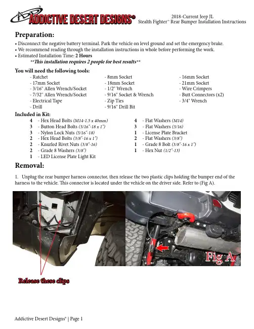
Preparation:• Disconnect the negative battery terminal. Park the vehicle on level ground and set the emergency brake.• We recommend reading through the installation instructions in whole before performing the work.• Estimated Installation Time: 2 Hours**This installation requires 2 people for best results**You will need the following tools: - Ratchet - 8mm Socket - 16mm Socket - 17mm Socket - 18mm Socket - 21mm Socket - 3/16" Allen Wrench/Socket - 1/2" Wrench - Wire Crimpers - 7/32" Allen Wrench/Socket - 9/16" Socket & Wrench - Butt Connectors (x2) - Electrical Tape - Zip Ties - 3/4" Wrench- Drill - 9/16" Drill Bit Included in Kit:4 - Hex Head Bolts (M14-1.5 x 40mm) 4 - Flat Washers (M14) 3 - Button Head Bolts (5/16"-18 x 1") 3 - Flat Washers (5/16) 3 - Nylon Lock Nuts (5/16"-18) 1 - License Plate Bracket 2 - Hex Head Bolts (3/8"-16 x 1") 2 - Flat Washers (3/8") 2 - Knurled Rivet Nuts (3/8"-16) 1 - Grade 8 Bolt (3/8"-16 x 1") 2 - Grade 8 Washers (3/8") 1 - Hex Nut (1/2"-13) 1 - LED License Plate Light Kit Removal:1. Unplug the rear bumper harness connector, then release the two plastic clips holding the bumper end of theharness to the vehicle. This connector is located under the vehicle on the driver side. Refer to (Fig A).Release these clipsFig A2. Remove your OEM spare tire.3. Using a 16mm Socket, remove the bottom two bumper bolts and the two trailer plug bracket bolts. Save these bolts for reuse. (Fig B)Fig B4. Using a 16mm Socket, remove the bumper side support bolts (2 per side) that are accessible from underneath the truck on the outer section of the bumper. (Fig C)Fig C5. Using a 17mm Socket, remove the bumper mounting nuts (2 per side) which are accessible from underneath the vehicle. Then, remove the OEM bumper. (Fig D)Fig D6. Using an 8mm Socket, remove the three (per side) inner fender liner bolts referenced in (Fig E). Then, re-move the lower inner fender liner pieces from the vehicle.Fig E7. Remove the two bolts that hold on each bumper side support bracket. Then, remove both brackets from the vehicle. (Fig F)Fig F8. Use an 18mm Socket to remove the driver side tow hook bolts (x4). Then, use a 21mm Socket to remove the passenger side bumper mounting bracket bolts (x2). Remove the tow hook and both bumper mounting brackets from the vehicle. (Fig G)Fig G9. IF YOU HAVE A METAL BUMPER, FOLLOW THIS STEP. IF NOT, SKIP TO STEP 10. Remove the parking sensors from the OEM rear bumper. Do this by first spreading the tabs on the inner mounting ring and releasing the sensor out the back side of the bumper. Then, spread the tabs on the outer mounting ring to release it from the inner mounting ring. Finally, press the tabs in on the inner mounting ring to push it out the front side of the bumper. (Fig H)Spread these tabs andrelease the parkingsensor from the rearSpread these tabsand release the outermounting ring fromthe rearFig H10. IF YOU HAVE A PLASTIC BUMPER, FOLLOW THIS STEP. IF NOT, SKIP TO STEP 11. Remove the parking sensors from the OEM Rear Bumper. Do this by first spreading the tabs on the mounting ring and releasing the sensor out the back side of the bumper. Then, take a putty knife, scraper, or something similar and work it between the sensor ring mounting plate and the rear bumper. Use the scraper to cut through the plas-tic welds holding that plate to the OEM bumper. Once the plastic welds have been broken, the plate will be free from the bumper. M ake sure to keep track of the order/orientation of the sensors on the OEM bumper as you will need to install them in the same order/orientation on your new bumper. (Fig I)Use a scraperto separatethe mountingplate fromthe bumperThis is whatit looks likeonce itsseparated Fig I11. Release the series of plastic clips holding the OEM Bumper Harness in the OEM Bumper. Then, remove the harness from the OEM Bumper. (Fig J)Fig JInstallation:12. If you have any lights to install on your new bumper, now is a good time to do so. Please follow the light manufacturer's installation guide for mounting/wiring information.13. Install the supplied license plate bracket. Do this by lining the mounting holes on the bracket up with the mounting holes on the bumper. Then, use the supplied 5/16" Bolts (x3), 5/16" Washers (x3), and 5/16" Lock Nuts (x3) to secure the bracket to the bumper. Install all bolts loosely, then go back and torque them to 13 foot pounds. (Fig K)Fig K14. IF YOUR PARKING SENSORS LOOK LIKE THE SENSORS IN STEP 9, FOLLOW THIS STEP. IF NOT, SKIP TO STEP 15. Install the OEM Parking Sensors on your new bumper by pressing the inner mounting ring in from the front until it clicks into place. Then, press the outer ring onto the inner ring from the backside. Final-ly, press the sensor into place from the back side. (Fig L)Fig L15. IF YOUR PARKING SENSORS LOOK LIKE THE SENSORS IN STEP 10, FOLLOW THIS STEP. IF NOT, SKIP TO STEP 17. Before installing the parking sensor mounting plates, you will have to trim both outer plates. Do this by setting them in place in their precut holes (push them in place from the back side keeping the same orientation as on the OEM bumper). Then, mark out where you will have to make your cuts. We cut them so that none of the mounting plate is visible from the front side of the bumper. Refer to (Fig M & Fig N)Before AfterFig M16. IF YOUR PARKING SENSORS LOOK LIKE THE SENSORS IN STEP 10, FOLLOW THIS STEP . IF NOT, SKIP TO STEP 17. Use a strong epoxy to glue the parking mounting plates to your new bumper. Do this by applying epoxy on the front face of the mounting plate. Then, push the sensor mounting ring through the precut hole in the bumper from the backside of the bumper, so that the front face of the mounting plate gets glued to the back side of the bumper. Once the glue has set, push the sensor into the back side of the mounting ring until it clicks into place. (Fig O)Before After Fig NFig O18. Mount your license plate to the license plate bracket using the supplied LED License Plate Lights as yourmounting bolts. Make sure the LED Lights are facing down at your license plate. (Fig Q)Fig Q17. Take the OEM bumper harness and plug it into the newly installed parking sensors. Make sure to leave the main plug of the harness on the driver side of the bumper. (Fig P)Fig P20. Cut the license plate light connector off the OEM Harness. Twist both Red Wires from the LED Lights together and butt connect them to the White/Blue Wire from the OEM Harness. Then, twist both Black Wires from the LED Lights together and butt connect them to the black wire from the OEM Harness. (Fig S)Fig S21. Re-cover the now exposed wiring with either electrical tape or wire loom and zip tie the OEM Bumper Har-ness how you would like it.19. Locate the license plate light connector on the OEM Bumper Harness. Remove the conduit far enough back to allow this connector to reach the ends of the LED License Plate Light wires. (Fig R)Fig R22. IF YOUR OEM BUMPER DID NOT HAVE THE BUMPER MOUNTING BOLTS REFERENCED IN STEP 3, FOLLOW STEPS 22 & 23. OTHERWISE, SKIP TO STEP 24. Find the holes on the bottom of the rear frame section. These holes are referenced in (Fig T) and are hexagon shaped. Take a 9/16" Drill Bit and drill them so they are circular.Fig T23. Find the supplied 3/8" Grade 8 Bolt (x1), 3/8" Grade 8 Washers (x2), and 1/2" Nut (x1). Assemble them as shown in (Fig U) to create a rivet nut installation tool. Once this tool has been assembled, place the supplied 3/8" Rivet Nuts in the newly drilled holes. Loosely thread the rivet nut installation tool into the rivet nuts. Then, while holding the 1/2" Nut steady, thread the rivet nut tool into the rivet nut until it gets tight. Once it is tight, back the tool out and the rivet nut will be set.Fig U24. Set your new bumper in place on the vehicle. Secure it to the vehicle using the supplied M14 Bolts (x4) and M14 Washers (x4). Do not reuse the stock bolts and leave these bolts loose for now. (Fig V)Fig V25. Use a 16mm Socket to install the lower bumper bolts that were set aside in Step 3. If your OEM bumper did not have those bolts, then install the supplied 3/8" Bolts (x2) and 3/8" Washers (x2) through these holes into your newly installed Rivet Nuts. (Fig W)Fig W26. Position the bumper so that it is straight in relation to the tailgate and is level when viewed from the side. Then, go back and tighten all mounting bolts to OEM torque specs.27. Plug in the connector from Step 1 and reinstall the plastic clips that hold it in place. 28. Set the trailer plug bracket in place, then reinstall the two trailer plug bracket bolts from Step 3. (Fig X)Fig XFor Additional Support or Technical Questions,Please Call 480-671-0820 or This product is protected by one or more U.S. patents/patents29. Stand back and enjoy your new Stealth Fighter™ Rear Bumper. 30. Check and re-tighten, if needed, all mounting bolts after 100 miles and periodically thereafter.。
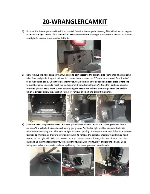
20-WRANGLERCAMKIT1)Remove the license plate and black trim bracket from the license plate housing. This will allow you to gainaccess to the light harness into the vehicle. Remove the license plate light from the bracket and install the new light lens/camera included with the kit.2)Now remove the floor panel in the trunk area to gain access to the driver’s side rear panel. The carpeting,false floor and plastic tray just pull out to remove. Now remove the 2 Torx head screws at floor level of the d river’s side panel. Once those are removed, you must detach the back side plastic piece where the top roll bar comes down to meet the plastic panel, this will simply pull off. Once that backside panel is removed you will see 1 more 10mm bolt holding the re st of the driver’s side rear panel to the vehicle which is directly below the seat belt retractor, remove this bolt and pull off the panel.3)Once the rear side panel has been removed, you will now have access to the rubber grommet in thecorner of the vehicle, this contains all wiring going down for the tail light and license plate bulb. We recommend removing the driver rear taillight for easier passing of the camera harness; it is also a suitable location to find reverse trigger power and ground. To remove the taillight, unscrew the 2 Phillips head screws on the right side. When removed, run your camera harness through the same hole as the plate bulb and up into the taillight cavity to access the reverse wire (white/gray) and ground (black). Once wiring connections are made continue up through the round grommet into the cab.4)Once through the grommet, run the harness to the front of the vehicle tucking it beneath the trim carpetand plastic panels towards the front. When at the front, remove the panel below the steering column by unclipping it. Once panel is removed, take out the 2 – 7mm bolts at each top corner of the opening. Now remove the rubber tray on top of the dash to remove 1 more bolt. Next move to the window controls which can be popped out to reveal the last bolt holding on the dash piece. Once all 4 bolts are removed, unclip the dash panel and set aside.5)With the dash panel removed, proceed to take out the factory radio by removing the 4 bolts securing it tothe dash. With the radio removed, simply plug in the harnessing that was included with the bypassmodule by t-harnessing it into the existing wiring. It is possible that the WHITE T-Harness connector may not be populated from the factory; this is not an issue so continue the install by plugging the male end into the radio. Please note: The back-up camera’s RCA will plug into the WHITE T-Harness RCA labeled “CAM IN” you will not use any RCA connections on the Gray T-Harness. Once the Gray and White T-Harnesses have been plugged in, plug the black Molex connector into the programming box. Witheverything plugged in turn on the vehicles ignition and let the radio completely boot up, if everything is connected properly simply put the vehicle in reverse and the camera image will appear.FINISHED。
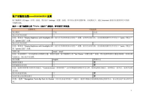
客户可编程功能——Uconnect8.4设置
按下触摸屏上的Apps(应用)按钮,然后按下Settings(设置)按钮,即可显示菜单设置屏幕。
在此模式下,通过Uconnect系统可以使用所有可用的
可编程功能。
显示——按下触摸屏上的“Display(显示)”按钮后,即可使用下列设置:
1
单位——按下触摸屏上的“Units(单位)”按钮后,即可使用下列设置:
语音——按下触摸屏上的“Voice(语音)”按钮后,即可使用下列设置:
时钟:按下触摸屏上的“Clock(时钟)”按钮后,即可使用一列设置:
2
安全和驾驶辅助:按下触摸屏上的“Satety/Driving Assistance(安全/驾驶辅助)”按钮后,即可使用下列设置:
3
制动:按下触摸屏上的“Brake(制动)”按钮后,即可使用下列设置:
车灯:按下触摸屏上的“Lights(灯光)”按钮后,即可使用下列设置:
自动舒适系统—如果配备,按下触摸屏上的“Auto-On Comfort Systems(自动开启舒适功能系统)”按钮后,即可使用下列设置:
4
车门和车锁:按下触摸屏上的的“Doors & Locks(车门和车锁)”按钮后,即可使用下列设置:
5。
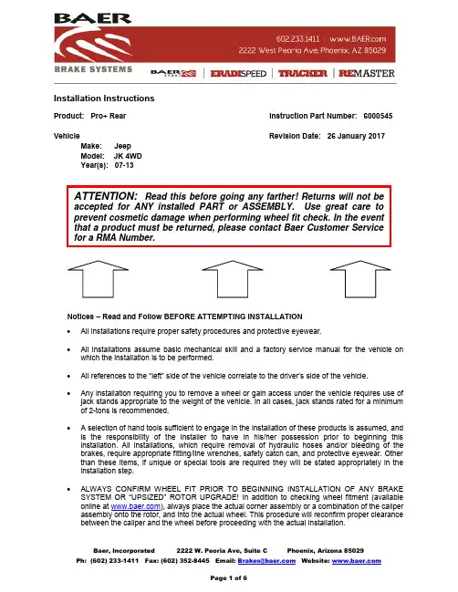
Installation InstructionsProduct: Pro+ Rear Instruction Part Number: 6000545 Vehicle Revision Date: 26 January 2017 Make: Jeep Model: JK 4WD Year(s): 07-13Notices – Read and Follow BEFORE ATTEMPTING INSTALLATION∙All installations require proper safety procedures and protective eyewear.∙ All installations assume basic mechanical skill and a factory service manual for the vehicle on which the installation is to be performed.∙ All references to the “left” side of the vehicle correlate to the driver’s side of the vehicle.∙Any installation requiring you to remove a wheel or gain access under the vehicle requires use of jack stands appropriate to the weight of the vehicle. In all cases, jack stands rated for a minimum of 2-tons is recommended.∙A selection of hand tools sufficient to engage in the installation of these products is assumed, and is the responsibility of the installer to have in his/her possession prior to beginning this installation. All installations, which require removal of hydraulic hoses and/or bleeding of the brakes, require appropriate fitting/line wrenches, safety catch can, and protective eyewear. Other than these items, if unique or special tools are required they will be stated appropriately in the installation step.∙ALWAYS CONFIRM WHEEL FIT PRIOR TO BEGINNING INSTALLATION OF ANY BRAKE SYSTEM OR “UPSIZED” ROTOR UPGRADE! In addition to checking wheel fitment (available online at ), always place the actual corner assembly or a combination of the caliper assembly onto the rotor, and into the actual wheel. This procedure will reconfirm proper clearance between the caliper and the wheel before proceeding with the actual installation.∙Returns will not be accepted for systems that have been partially or completely installed. Use extreme care when checking wheel fitment to prevent any cosmetic damage.∙When installing new Baer rotors, be sure to follow the direction of rotation indicated on the rotor hat area with either an arrow, or an “L” for left, or an “R” for right, or both. “L” or left always indicates the driver’s side of US spec vehicles. Images shown are “L” left rotors:∙ A proper professional wheel alignment is required for any system requiring replacement of the front spindles, or tie rod ends. Follow factory prescribed procedures and specifications unless otherwise indicated.∙At any point, stop the installation if anything is unclear, or the parts require force to install. Consult directly with Baer Technical Staff in such instances to confirm details. Please have these instructions, as well as the part number of the component (part numbers are machined into the brackets) that is proving difficult to install, as well as the make, model, and year (date of vehicle production is preferred) of your vehicle available when you call. Baer’s Technical Staff is available from 8:30a.m. - 5:00p.m. Mountain Standard Time (Arizona does not observe Daylight Savings Time) by phone: (602)-233-1411 Monday through Friday.INSTALLATION:1. Remove all the rear end axle/brake components, caliper, rotor, axle, bracket, brake shoe, etc.Thoroughly clean the face of the axle housing flange to ensure proper fitment of the new components. Save the OEM hardware and axle retainer plate as they will be reused. The OEM brake shoe bracket will not be reused, the Baer banksia plate assembly replaces that bracket.2. Install the Baer banksia plate assembly (Figure 1). The assembly comes with the Baerintermediate bracket attached to the inboard side of the plate. The bracket bolts are just snugged as they will need to be removed for shimming later in the install.Figure 1: Baer banksia assembly (drivers side)3. Install the axle and axle retainer plate using the OEM hardware. The banksia plate will be held inplace by the OEM axle retainer plate bolts. See Figures 2 and 3 for reference.Figure 2: Banksia, axle and axle retainer plateIntermediate BracketAxle Retainer PlateBanksiaFigure 3: Banksia, axle and axle retainer plate (inboard view)4. Install the correct side rotor onto the axle and secure with two or three lug nuts and washers toprevent scratching the rotor hat. With the pads removed install the caliper (bleed screw pointing upward) using the supplied M12-1.75 x 45mm socket head bolts. Snug the bolts for now asshimming will require removal. See Figures 4 and 5 for reference.Figure 4: Rotor and caliper installed (outboard view)Figure 5: Rotor and caliper installed (inboard view)5. Perform the Shimming Procedure which is located on the last page. When the procedure hasbeen completed continue with the Step 6.6. Install the brake hose to the caliper using the supplied banjo bolt and copper washer (one copperwasher on each side of the banjo fitting). Finger tighten the banjo bolt. Connect the hose to the hardline using one of the supplied fittings and install the hose lock.***IMPORTANT: Position the hose to avoid interference with the wheel and suspension components through the entire range of motion. Tighten fitting and banjo bolt to 15-20 ft∙lbs.7. Repeat the procedure for the other side.Refer to Bleeding and Pad Bedding & Rotor Seasoning Procedures contained on a separate sheet,or on For service components and replacement parts contact your Baer Brake Systems Tech Representative.Figure 6: Shim location。

铃木吉姆尼安装博文BOWON定制DVD导航与倒车可视系统铃木吉姆尼是由日本铃木公司生产的轻型越野车,英文名称为“JIMNY”。
她在越野爱好者族群中也享有很高的地位。
但是在中国大地上奔驰的吉姆尼,全部为进口车型。
这可爱的小车因为市场定位的原因,至今也没有国产。
下图为铃木吉姆尼安装博文BOWON定制DVD导航与倒车可视系统。
博文BOWON定制铃木吉姆尼DVD导航一体机
拆下原车主机,安装博文BOWON定制铃木吉姆尼DVD导航一体机。
博文BOWON定制铃木吉姆尼DVD导航一体机安装完毕,主菜单显示效果。
博文BOWON定制铃木吉姆尼DVD导航一体机安装完毕,使用凯立德导航地图。
博文BOWON通用BWTY-1106倒车摄像头
博文BOWON通用BWTY-1106倒车摄像头安装在牌照灯饰条上。
博文BOWON通用BWTY-1106倒车摄像头安装好的效果。
铃木吉姆尼安装博文BOWON倒车可视系统完毕,倒车影像显示效果。


Replacement Soft Top1997-2006 TJ WranglerPart #: RT10115T, RT10215T, RT10315, RT10335, RT10335T,RT10336, RT10337, RT10337T, & RT10435TKit Components:Replacement Top(2) Side Windows(1) Rear Window(2) Soft Upper Door Skins (If applicable)-Read all instructions carefully prior to starting installation.-We recommend installing this top in temperatures 70F (21C) and above. This will make installation easier and reduce the risk of damaging the top. Laying all of the pieces of the top in the sun is also suggested to ease installation.-Do not over-stress the zippers or straps. Failure to comply may damage the top or windows.1.Ensure that all parts are accounted for.2.Remove the old soft top, windows, and tailgate bar. The bow assembly will remain on the vehicle. Do not removethe factory door surrounds. Save any hardware removed as it will be reused to install replacement top.3.Unpack and separate the Replacement Top and Side and Rear Windows. Carefully place the windows aside for lateruse.4.Fold the bow assembly back into the down position.y the Replacement Top inside the Jeep with the inside facing up. The plastic strip sewn into the front of the topshould face the rear of the vehicle.6.Pull the plastic strip up to the header channel and line up the 14 holes in the header channel. Using the factoryscrews attach the top to the header channel.7.Fold the top around the header channel and attach the corners of the top to the header channel with the factoryscrews.8.Flip the Replacement Top over the back of the Jeep so the inside faces down.9.Fold the bow assembly into the up position.10.Snap the rear of the top to the rear bow. Attach the center of the top to the center bow using the hook and loopfasteners.11.On the inside of the vehicle, attach the soft top header channel latches to the windshield frame. Do not fully latchthe latches at this time.12.Install Side Windows by starting the zipper only a few inches. Tuck the front of the window into the channel on thedoor surround using the sewn in plastic strips.13.Tuck the sewn in plastic strips of the Replacement Top into the tub rails at each rear corner.14.Fully zip the Side Windows and tuck the sewn in plastic strips into the tub rail. Secure the hook and loop fastenersaround the zippers.15.Install the Rear Window by zipping it to the Replacement Top. Keep the last 8-12” of each side unzipped. Do nottuck the window into the tailgate bar retainers yet.16.Slide the tailgate bar (Sold Separately P/N TN27015) into the Rear Window with the weatherstrip facing out andslide it into the tailgate bar retainers.17.Tuck the plastic strips that are sewn into the sides of the Replacement Top into the top of the door surroundchannels.18.Fully zip the final 8-12” of the Rear Window. Tuck the plastic st rips on either side of the Rear Window into thetailgate bar retainers.19.Fully latch the header channel latches.20.If installing a Replacement Top w/ Soft Upper Door Skins refer to the Soft Upper Door Skin Installation Instructions.21.Make any adjustments necessary to ensure the top is centered and fits properly. Creases in the top fabric ofwindows will fade away once the top is installed.22.Small adjustments to the top may be necessary once the top warms up and any creases are smoothed out.While every attempt is made to ensure that the information contained in these instructions is correct, no liability can be accepted by the authors for loss, damage, or injury caused by any errors in, or omissions from the information given. All service should be performed by qualified mechanics. Crown Automotive Sales Co .,Inc.cannot be held responsible for any mechanical work performed. Standard and accepted safety precautions should be used in every procedure。
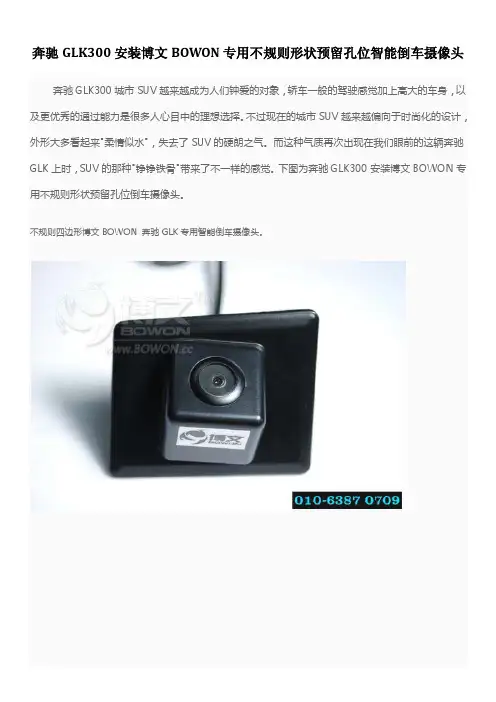
奔驰GLK300安装博文BOWON专用不规则形状预留孔位智能倒车摄像头奔驰GLK300城市SUV越来越成为人们钟爱的对象,轿车一般的驾驶感觉加上高大的车身,以及更优秀的通过能力是很多人心目中的理想选择。
不过现在的城市SUV越来越偏向于时尚化的设计,外形大多看起来"柔情似水",失去了SUV的硬朗之气。
而这种气质再次出现在我们眼前的这辆奔驰GLK上时,SUV的那种"铮铮铁骨"带来了不一样的感觉。
下图为奔驰GLK300安装博文BOWON专用不规则形状预留孔位倒车摄像头。
不规则四边形博文BOWON 奔驰GLK专用智能倒车摄像头。
不规则四边形博文BOWON 奔驰GLK专用倒车摄像头安装在原车预留孔位置。
不规则四边形博文BOWON 奔驰GLK专用智能倒车摄像头安装好的效果。
调整不规则四边形博文BOWON 奔驰GLK专用智能倒车摄像头。
奔驰GLK300安装博文BOWON专用不规则形状预留孔位智能倒车摄像头安装,倒车影像显示效果。

车架与保险杠目录页码保险杠概述 (1)原理 (1)前缓冲器拆卸 (1)安装 (1)前饰板拆卸 (1)安装 (1)后缓冲器拆卸 (2)安装 (2)后饰板拆卸 (2)安装 (4)车架概述 (4)技术规范 (4)页码前滑动保护板拆卸 (7)安装 (7)前拖车钩拆卸 (7)安装 (7)燃油箱滑动保护板概述 (7)后拖车钩拆卸 (7)安装 (7)拖车挂接装置拆卸 (8)安装 (8)分动器滑动保护板拆卸 (8)安装 (8)保险杠概述大切诺基的保险杠由固定在整体式车身车架横梁上的缓冲器和前后饰板组成。
某些大切诺基车型还装有紧固在整体式车身的前横梁上的拖车钩支架。
原理保险杠用来吸收小的冲击并且保护外部金属板件。
前缓冲器拆卸(1)拆下前饰板(参见第13章“车架与保险杠/保险杠/前饰板——拆卸”)。
(2)拆下将缓冲器连到饰板的紧固件。
(3)将缓冲器与饰板分离。
安装(1)将缓冲器放置在饰板上 。
(2)安装将缓冲器固定在饰板上的紧固件。
(3)安装前饰板(参见第13章“车架与保险杠/保险杠/前饰板——安装”)。
前饰板拆卸(1)升起并支撑汽车。
(2)转动前车轮以便能接近铆钉,并拆下饰板固定在车轮衬垫上的塑料铆钉。
(3)拆下将饰板固定在翼子板上的螺栓(图1)。
(4)拆下将前饰板固定在散热器下横梁挡泥板处的塑料按销(图2)。
(5)如果装有雾灯,将其插接器拔下。
(6)拆下将前罩/散热栅格固定在散热器上横梁的螺钉(图3)。
(7)向前滑动饰板使其脱离汽车。
安装(1)将饰板平滑地安装到汽车上并将其与前翼子板底部的凸缘啮合。
(2)安装将前罩/散热栅格固定在散热器上横梁的螺钉(图3)。
(3)安装将饰板固定在翼子板上的螺栓(图1)。
(4)如果装有雾灯,将其插接器连上。
(5)安装将饰板固定在车轮衬垫上的塑料铆钉。
图3 前饰板1.螺钉 2.饰板 图1 前饰板1.车身 2.饰板后缓冲器拆卸(1)拆下后饰板(参见第13章“车架与保险杠/保险杠/后饰板——拆卸”)。
奇骏倒车雷达安装方法
1. 首先,确定您所购买的奇骏倒车雷达套装中是否包含了所有安装所需的零件和工具。
2. 确定安装位置:在车辆后保险杠内侧找到合适的位置,通常是在车辆中央位置的下方。
使用工具,如螺丝刀和锤子,清理并准备好安装位置。
3. 安装传感器:将倒车雷达传感器安装到所选位置上。
使用提供的螺丝将传感器固定到车辆后保险杠内侧。
4. 连接电缆:根据说明书中的指引,连接传感器的电缆到电源和控制模块中。
按照说明书上的指引确保所有电缆都连接到正确的位置。
5. 安装显示屏:一般来说,奇骏倒车雷达套装会包含一个显示屏。
根据说明书中的指引,安装显示屏到车内的适当位置上,例如安装在仪表板或挡风玻璃上。
6. 连接电源:连接显示屏的电缆到控制模块上。
确保电源线连接到适当的电源引线上。
7. 连接控制模块:根据说明书中的指引,连接控制模块到电源和传感器上。
8. 测试:完成所有安装步骤后,进行测试以确保倒车雷达系统正常工作。
驾驶
车辆,进行倒车测试,观察显示屏上的距离指示和警报声。
9. 完成安装:在测试通过后,使用工具将所有零件和线路固定好,确保安装牢固和整洁。
如有不确定的步骤或问题,建议请找到专业的车辆安装技师进行安装。
Step 1: (Read instructions prior to installation) Secure vehicle on jack stands (refer to your own er’s manual for specified jack stand positions.Step 2: Disconnect the battery located under the front passenger seat.Step 3: Remove the fuse box and mounting tray.Step 4: Remove the air inlet tube from the air box.Step 5: Remove the lower under tray.Step 6: Remove the right and left chassis support brackets.Step 7: Remove the OE exhaust system.Step 8: Unplug the O2 sensors (mark the O2 sensor connectors so they are reinstalled in the cor rect position.Step 9: Unbolt the driver’s side and passenger side Catalytic Converter pipes from the manifolds and remove.Step 10: Remove the drive shaft.Step 11: Unplug the O2 sensors on the right and left exhaust manifolds.Step 12: Remove the nut on the dip stick tube, you do not have to remove the dip stick from the oil pan.Step 13: Remove the (x8) bolts on the right side exhaust manifold and remove the manifold and gasket.Step 14: Remove the (x8) bolts on the left side exhaust manifold and remove the manifold and gas ket.Step 15: Install the O2 extension leads provided in the hardware kit, the left rear O2 uses the 15” O2 extension lead all others use the 9” extension leads. The left rear O2 extension lead can be routed underneath the heat shield by removing the nut on the heat shield lower the heat shield and route the extension lead underneath this will keep the wires away from the driveshaft.Step 16: Install the passenger side header gasket provided onto the cyl head using the 8mm bolts provided only on the bottom bolt holes. (thread in just enough to hold the gasket in place this will allow for an easier installation of the header.CAUTION: Allow time for your vehicle to cool down prior to installation. When working on or under your vehicle proceed with caution. Exhaust systemsreach high temperatures and may cause serious burns. Wear protective safety equipment; eye goggles and gloves to ensure a safe installation. aFe recommends professional installation on our products.06-86140Updated: June 2015Page 1 of 2Parts Included:• 3" SS Band Clamp (x2)• Gasket Manifold (x2)• 02 Extension Leads 9” (x3)• 02 Extension Leads 15” (x1)• Hex, flange bolt 8mm (x15) • Spacer, Header Bolt (x1) • Zip Ties (x4)• Heat Shield 6" x 12" (x2)Step 17: Install the passenger side aFe power header using the supplied 8mm bolts. Use the original header bolt and supplied spacer on the dip stick header bolt and original nut. Tighten to manufactures torque speci fications.Step 18: Install the driver’s side header gasket provided onto the cyl head using the 8mm bolts provided only on the bottom bolt holes. (thread in just enough to hold the gasket in place this will allow for an easier insta lation of the header.Step 19: Install the driver’s side aFe power header using the supplied 8mm bolts. Tighten to manufactures torque specifications.Step 20: Support the transmission and remove the cross member.Step 21: Reinstall the driveshaft and reinstall the cross member.Step 22: Install the supplied band clamp onto the passenger side aFe power Catalytic Converter pipe and install onto the header, do not tighten clamp.Step 23: Install the supplied band clamp onto the driver’s side aFe power Catalytic Converter pipe and install onto the header, do not tighten clamp.Step 24: Remove the O2 sensors from the OE manifolds and Catalytic Converter pipes and reinstall them on the aFe power Catalytic Converter extension pipes.Step 25: Plug in O2 sensors and fasten extension leads out of the way using the cable ties provided in the hard ware kit.Step 26: Reinstall the Right and Left chassis support brackets.Step 27: Reinstall the OE exhaust system.Step 28: Tighten the right and left band clamps on the aFe power Catalytic Converter pipes.Step 29: Install the heat shield adhesive supplied in the kit to the right and left OE heat shields behind the catalytic converters. (See Figure A.)Step 30: Reinstall the air inlet tube on the air box.Step 31: Reinstall the fuse box and mounting tray.Step 32: Reinstall the lower under tray.Step 32: Reconnect the battery.Step 34: Your installation is now complete. It is recommended to re-tighten all exhaust components after 50-100 miles.CAUTION: Allow time for your vehicle to cool down prior to installation. When working on or under your vehicle proceed with caution. Exhaust systems reach high temperatures and may cause serious burns. Wear protective safety equipment; eye goggles and gloves to ensure a safe installation. aFe recommends professional installation on our products.06-86140Updated:June 2015Page 2 of 2Parts Included:• 3" SS Band Clamp (x2)• Gasket Manifold (x2)• 02 Extension Leads 9” (x3)• 02 Extension Leads 15” (x1)• Hex, flange bolt 8mm (x15) • Spacer, Header Bolt (x1) • Zip Ties (x4)• Heat Shield 6” x 12” (x2)(Figure A.)Heat Shield。
®Quadratec ®QRC Rocker Guards & Side ArmorInstallation Manual for 4 Door ’07-Current JK Wrangler Vehicles#12004.3201 & #12004.3211TO REDUCE RISK OF SERIOUS INJURY OR PROPERTY DAMAGE:READ ALL SAFETY MESSAGES AND UNDERSTAND ALL INSTRUC-TIONS AND PROCEDURE NOTICES BEFORE ATTEMPTING TO INSTALL OR USE THIS PRODUCT. FOLLOW ALL INSTRUCTIONS AND WARNINGS WITH PRODUCT & VEHICLE OWNERS MANUAL.THIS PRODUCT IS INTENDED TO REDUCE RISK OF OFF-ROAD BODY PANEL DAMAGE AND ASSIST IN ENTRY/EXIT FROM VEHICLE. YOUR TUBE STEP IS NOT INTENDED TO INCREASE OCCUPANT PROTECTION OR REDUCE VEHICLE DAMAGE IN EVENT OF ACCIDENT.PROPERLY TORQUE AND RECHECK FASTENERS AND SECURITY OF STEP TREAD AFTER 250 MILES AND FREQUENTLY THERE-AFTER. INSPECT AND DO NOT USE AS A STEP IF DAMAGED. DO NOT USE ROCKER GUARDS AS A WINCH/SELF-RECOVERY ATTACHMENT POINT.CHECK STATE AND LOCAL HIGHWAY SAFETY LAWS REGARDING PERMITTED ON-ROAD EQUIPMENT.Rocker GuardsRocker Guards Side Armor with StepSide Armor with Step12004.320112004.3211®Before You Begin Installation:Congratulations on your purchase of the Quadratec QRC Rocker Guards for your Jeep ®Wrangler.When unpacking, check to make sure all parts are included and not damaged due to shipping. If any part is missing or broken, please call Customer Service at 800-745-6037 as soon as possible.Due to the length and bulk of theseguards, we strongly suggest you get the help of a friend for steps that involve lifting, locating or holding the side steps during installation.Thank you again for your purchase and let’s start the installation process.As you unpack your rocker guards, be careful not to scratch the finish with a knife or razor. We suggest placing the unpacked guards back into the original box so it does not get scratched before the installa-tion begins. It is highly recommended that a second person assist with the installation of these rocker guards.A hazardous situation which, if not avoided, could result in death or serious injury. You CAN be KILLED or SERIOUSLY HURT if you don’t follow instructions.A hazardous situation which, if not avoided, could result in minor or moderate injury. You CAN be moderately HURT and also may suffer property damage if you don’t follow instructions.Careful attention is required to this instruction or operation but does generally not relate to personal injury. Damage to your Quadratec ®product or other property may result if you don’t follow instructions.These custom fit guards have been designed for long life and great looks.With proper care, they are designed to provide years of use.Please see page 7 in this instruction booklet for all suggested care for your Quadratec Rocker Guards.Product Care and Maintenance:A Few Words About Product Safety: Your Rocker Guards are designed to enhance the utility and enjoyment of your off road capable vehicle. Before installation, please take a moment to review the following safety informationand installation instructions. Important safety information is generally preceded by one of three signal words indicating the relative risk of injury. The signal words mean:®Installation Hardware:You can identify the left and right hand pieces by locating the Quadratec oval logo. The logo should be at the front of the part.You must remove factory installed “Rock Rails”, side steps or running boards before installation of your new rocker guards.These instructions are shared for the Quadratec side steps andQuadratec rock rails for JK. The installation instructions are the same for both. Pictures may not show the part you purchased but the in-stallation will be the same.PARTS LIST:Driver (Left)Rocker GuardQTY 1Passenger (Right)Rocker Guard QTY 1Nut Plates:A) 10mm nut plate QTY 6Hex Bolts:B) 10 x 35 mm bolts QTY 6 C) 8 X 35 mm boltsQTY 6Button Head Bolts:D) 6 X 25mm button head bolts QTY 12Nylon Lock Nuts:E) 6mm nylock nutQTY 12Flat Washers:F) 10mm flat washer QTY 6G) 8mm flat washer QTY 6H) 6mm flat washer QTY 24Lock Washers:I) 10mm lock washer QTY 6J) 8mm lock washer QTY 6Supplied Tools:K) 4mm Hex KeyQTY 1EC A B DF G JH I K®Install the 6mm button head boltsthrough the pinch weld and the mount-ing bracket with a washer on both sides and secure with 6mm nylock nut using the provided 4mm hex wrench and a 10mm socket. (Figure 3)Do not fully tighten at this time. Repeat on the 5 remaining holes. (Figure 4)Locate the 6 holes along the factory pinch weld of your vehicle as show in picture. (Figure 1)Starting at the front of the vehicle position the mounting tabs of the rock rails behind the pinch weld and align the holes with the factory pinch weld holes as shown. (Figure 2)Step 1:Step 3:Figure 1Figure 2Figure 3Figure 4Step 2:Step 4:On Newer model JK’s locate the 2 vertical threaded holes behind the pinch welds. Align the holes in the brackets with these holes. (Figure 5) Install the 8mm hex bolts, lock washers, and washers and snug with a 13mm socket. Repeat on the two remaining holes. (Figure 6)Figure 5Figure 6 Figure 7Figure 8Older JKs do not have a threaded insert. The supplied 10mm nut plate will have to be installed through the adjacent hole in the body.You may have to hold the plate in posi-tion using a finger. (Figure 7) Once the plate is installed secure with 10mm bolt, lock washer, and washer. Snug with a 16mm socket. (Figure 8) Now fully tighten the pinch weld bolts and then the vertical mounting bolts. Repeat steps on the opposite side.Step 5:Step 6:Step 7:Installation is complete.®®Completed Installation:Rocker GuardsSide Armor with StepYour Rocker Guards have been designed and manufactured to provide years of use. However, like any product, general maintenance is required to keep it looking new.Because the guards are located on the underside of the vehicle, they are subject to potential rock chips and other debris potentially causing portions of the paint to chip off. For touch ups, we recommend using a textured black spray paint sprayed on a piece of cardboard and cotton swab to gently fill in these chips. This will prevent any rust from forming.Product Care and Maintenance:Rocker GuardsSide Armor with Step®Quadratec® Exclusive Three Year Limited WarrantyYour Quadratec®branded accessories are covered by the following Limited Warranty provided exclusively by Quadratec, Inc., 1028 Saunders Lane, West Chester PA 19380.This Limited Warranty is the only warranty made in connection with your purchase. Quadratec neither assumes nor authorizes any vendor, retailer or other person or entity to as-sume for it any other obligation or liability in connection with this product or Limited War-ranty. This Limited Warranty does not apply and is not cumulative to any accessory or part distributed by Quadratec for which the Manu-facturer provides a separate written warranty. What is Covered: Subject to the terms, exclu-sions and limitations herein and with respect only to Quadratec branded accessories first sold in the United States, Quadratec warrants to the initial retail purchaser only that your Quadratec accessory shall be free of defects in material and workmanship: for a period of three (3) years from date of retail purchase. This Limited Warranty is not assignable and shall terminate upon sale of the vehicle upon which the Quadratec accessory is installed or other transfer third persons.All other warranties are hereby disclaimed, ex-cept to the extent prohibited by applicable law in which case any implied warranty of mer-chantability or fitness for a particular purpose on this product is limited to 3 year from date of initial retail sale. Quadratec reserves the rights to: (a.) require invoice or other proof your ac-cessory is within the terms of this Limited Warranty as a condition of warranty service and, (b.) make future revisions to this product and Limited Warranty without prior notice or obligation to upgrade your product.What is Not Covered:Your Quadratec Limited Warranty does not cover products or parts Quadratec determines to have been damaged by or subjected to:(a.) installation damage, alteration, modifica-tion, combination with other parts, failure to maintain or improper repair or service, (b.) nor-mal wear & tear, cosmetic damage or damage from moisture or water immersion, (c.) Acts of God, accidents, misuse, negligence, inadequate mounting or impact with vehicle(s), obstaclesor other aspects of the environment, (d.) theft, vandalism or other intentional damage. Remedy Limited to Repair/Replacement:The exclusive remedy provided hereunder shall, upon Quadratec inspection and at Q uadratec’s option, be either repair or replacement of prod-uct or parts (new or refurbished) covered under this Limited Warranty.Customers requesting warranty consideration should first contact Quadratec to obtain a RGA number(610-701-3336). All labor, removal, shipping and installation costs are customer’s responsibility.Other Limitations - Exclusion of Damages -Your Rights Under State Law:In consideration of the purchase price paid, nei-ther Quadratec nor any independent Quadratec distributor/licensee are responsible for any time loss, rental costs, or for any incidental, conse-quential, punitive or other damages you may have or incur in connection with any part or product purchased. Your exclusive remedy hereunder for covered parts is repair/replace-ment as described above.This Limited Warranty gives you specific rights. You may also have other rights that vary from state to state. For example, some states do not allow limitations of how long an implied war-ranty lasts and /or do not allow the exclusionor limitation of incidental or consequential damages, so the limitations and exclusions herein may not apply to you.©Quadratec, Inc. 2013. All Rights Reserved.3.29.13 L TR VersionPart #12999.3059®。
3651 N Highway 89 • Chino Valley, AZ 86323(928) 636-7080 • JEEP WRANGLER, RUBICON,UNLIMITEDROCK DOOR KITINSTALLATION INSTRUCTIONS 1980-1986 CJ 1987-1995 YJ KIT# 880011997-2006 TJ KIT# 880002007 JK KIT# 88002WARNINGBefore you install this kit, read and understand all instructions, warnings, cautions, and notes in this instruction sheet and in the vehicle owner’s manual.CAUTIONProper installation of this kit requires knowledge of the factory recommended procedures for removal and installation of original equipment components. We rec-ommend that the factory shop manual and any special tools needed to service your vehicle be on hand during the installation. Installation of this kit without proper knowledge of the factory recommended procedures may affect the performance of these components and the safety of the vehicle. We strongly recommend that a certified mechanic familiar with the installation of sim-ilar components install this kit.WARNINGAlways wear eye protection when operating power tools.WARNINGBefore you install this kit, block the vehicle tires to pre-vent the vehicle from rolling.Before Starting Installation1.Carefully read all warnings and instructions com-pletely before beginning.NOTEKit parts are prefaced by the word kit and appear in boldprint.2.Verify all parts have been received in this kit bychecking the parts list at the end of this document.3.Only install this kit on the vehicle for which it isspecified. If anytime during the installation you encounter something different from what is outlined in the instructions, call technical support at (928)636-7080.4.Park vehicle on a clean, dry, flat, level surface andblock tires so vehicle cannot roll in either direction.Inside Cab1.Open glove box and remove interior door lightswitch fuse from fuse panel.Prepare to Install Rock Doors1.Driver doora.Remove two nuts from two O.E. door hinges.NOTEIf parts are missing from kit, please be prepared to pro-vide the following information:1. Name of purchase location2. Bar Code on side of box3. Date above bar code4. Date inside box cover5. Inspector # from inside box cover NOTEThe location of the interior door light switch fuse may vary; check the owner's manual.O.E. HingesNutsO.E. Doorb.Open door and remove door restraint strap frompin and vehicle.c.JK Models: Unplug wire harness to each door.d.With door open, lift up and remove O.E. doorfrom two hinges and vehicle.e.Repeat above substeps for passenger side door.Install Rock Doors1.Driver doora.CJ, YJ, TJ Models: Install kit hinge onto kitdoor (driver) with kit bolt (3/8”-16 x 1”), kit washer (3/8” SAE) and kit nut (3/8”-16 flange).Snug, but DO NOT TIGHTEN.PinRestraint StrapDoorKit Hinge Kit Bolt(3/8”-16 x 1”),KitWasher (3/8” SAE),Kit Nut (3/8”-16 Flange)Kit Door(Driver)b.JK Models: Install two kit hinges onto kit door(driver) with four kit bolts (5/16 x 1” button head). Snug, but DO NOT TIGHTEN.c.Install kit cap onto kit door (driver).d.Install kit plug onto kit door (driver).NOTECJ, YJ, TJ models require one kit cap per door and JK models require two kit caps per door Kit HingeKit Bolt (5/16” x 1” button head)Kit Door (Driver)Kit PlugKit Cap CJ, YJ, TJ ModelsJK ModelsKit Pluge.Install kit door (driver) onto two O.E. hinges withtwo kit bolts and four kit washers (nylon).f.Install two kit washers and two kit nuts onto two kit bolts . DO NOT OVERTIGHTEN.g.Adjust kit door (driver) and TIGHTEN kit bolts .NOTECJ, YJ, TJ models: kit bolts (3/8”-16 x 3-3/4”) and kit washers (3/8” nylon)JK Models: kit bolts (7/16”-14 x 3-3/4”) and kit wash-ers (7/16” nylon)NOTECJ, YJ, TJ models: kit washers (3/8” nylon) and kit nuts (3/8”-16 Nylock) onto kit bolts (3/8”-16 x 3-3/4”).JK Models: kit washers (7/16” nylon) and kit nuts (7/16”-14 Nylock) onto kit bolts(7/16”-14 x 3-3/4”).Kit Bolt (3/8”-16 x 3-3/4”)Kit Washers (3/8” Nylon)Kit Door (Driver)Kit Washers (3/8” Nylon)Kit Bolt (3/8”-16 x3-3/4”)Kit Bolt (3/8”-16 x 3-3/4”)Kit Washer (3/8” Nylon),Kit Nut (3/8”-16Nylock)CJ, YJ Models:h.Temporarily install kit latch (driver) onto kit door(driver) with three kit bolts (1/4”-20 x 1”). DO NOT TIGHTEN.i.Position center of kit latch (driver) with door catch on body. Space kit latch accordingly with kit washers (1/4” SAE).Kit Door (Driver)Kit Latch (Driver)Kit Bolts(1/4”-20 x 1”),Kit Washers (1/4” SAE)Kit Latch (Driver)Kit Bolts(1/4”-20 x 1”),Kit Washers (1/4”SAE)YJ Models:Kit Washers (1/4” SAE)Catchj.Install kit latch (driver) onto kit door (driver) with three kit bolts (1/4”-20 x 1”), three kit washers (1/4” SAE) and any additional kit washers (1/4”SAE) to set kitlatch to catch.k.Adjust kit latch (driver), TIGHTEN kit bolts (1/4”-20 x 1”) and test kit door (driver). Readjust kit latch (driver) as necessary to obtain proper latch with catch.TJ Models:l.Install kit latch (driver) onto kit door (driver) with two kit bolts (1/4”-20 x 1”) and two kit washers (1/4” SAE). DO NOT TIGHTEN.m.Adjust kit latch (driver), TIGHTEN kit bolts (1/4”-20 x 1”) and test kit door (driver). Readjust kit latch (driver) as necessary to obtain proper latch with catch.Kit Door (Driver)Kit Bolts(1/4”-20 x 1”),Kit Washers (1/4”SAE)Kit Latch (Driver)CatchKit Door (Driver)Kit Latch (Driver)Kit Bolts(1/4”-20 x 1”),Kit Washers (1/4” SAE)JK Models:n.Install kit latch (driver) onto kit door (driver) withtwo kit bolts (1/4”-20 x 1”), two kit spacers , and two kit washers (1/4” SAE). DO NOT TIGHTEN.o.Adjust kit latch (driver), TIGHTEN kit bolts (1/4”-20 x 1”) and test kit door (driver). Readjust kit latch (driver) as necessary to obtain proper latch with catch.All Models:p.Open and close kit door (driver) ensuring properkit latch (driver) operation.NOTEKit latches have two stages. The first stage will result in kit doors not seated completely against kit plug .The second stage will properly seat the kit doors against the body. Adjust kit latches and kit hinges if the second stage is not attainable.Two Kit Spac-ersKit Latch (Driver)Kit Bolts(1/4”-20 x 1”),Kit Washers (1/4” SAE)q.Install kit weatherstrip onto kit door (driver).Cut kit weatherstrip if necessary for proper fit-ment.r.Installkit pad (long) onto upper bar of kit door (driver).s.Install kit pad (short) onto lower bar of kit door(driver).Kit Door (Driver)KitWeatherstripCJ, YJ Model TJ ModelKitWeatherstripKit Pad (Long)KitDoor (Driver)Kit Pad (Short)t.Install kit pad (cover, driver) onto kit pads .Adjust as necessary.u.Repeat above substeps for passenger door.After Completing InstallationMiscellaneous1.Check all fasteners to ensure they are tight.2.Ensure all wires, hoses, cables, etc. are properlyconnected and there is ample slack.WARNINGThis product is for Off-Road use only. It is NOT intended as a safety restraint device. Always make sure all occupants are wearing seat belts at all times.NOTEAll warranty information, instruction sheets, and other documents regarding the installation of this product must be retained by the vehicle owner. Information contained in the instructions and on the warranty card will be required for any warranty claims. The vehicle owner needs to understand the modifications made to the vehicle and how they affect vehicle handling and performance. Failure to provide the customer with this information can result in damage to the vehicle and severe personal injury.Kit Pad (Cover,Driver)Kit Door (Driver)Kit Parts ListQty.Description1Door (driver)1Door (passenger)1Label (logo)2Label (warning)1Pad (cover, driver)1Pad (cover, passenger)2Pad (long)2Pad (short)1ZH25 (Hardware bag, 88000) 4Bolt (1/4”-20 x 1”)2Bolt (3/8”-16 x 1”)4Bolt (3/8”-16 x 3-3/4”)2Cap2Hinge1Latch (driver)1Latch (passenger)2Nut (3/8”-16 flange)4Nut (3/8”-16 Nylock)2Plug4Washer (1/4” SAE)12Washer (3/8” nylon)2Washer (3/8” SAE)2Weatherstrip1ZH26 (Hardware bag, 88001) 6Bolt (1/4”-20 x 1”)2Bolt (3/8”-16 x 1”)4Bolt (3/8”-16 x 3-3/4”)2Cap2Hinge1Latch (driver)1Latch (passenger)2Nut (3/8”-16 flange)4Nut (3/8”-16 Nylock)2Plug24Washer (1/4” SAE)12Washer (3/8” nylon)2Washer (3/8” SAE)2Weatherstrip1ZH28 (Hardware bag, 88002) 4Bolt (1/4”-20 x 1”)8Bolt (5/16” x 1” button head)4Bolt (7/16”-14 x 3-3/4”)2Cap (urethane)4Hinge1Latch (driver)1Latch (passenger)2Nut (7/16”-14 Nylock)4Plug (plastic)4Sleeve4Washer (1/4” SAE)8Washer (7/16” nylon)2Weatherstrip Copyright 09/06Performance Automotive Group 。
&nbsWwW.Dongding.ccp;奔驰C级是族谱中销量最大的车型,也是奔驰所有车系中车型最全的一种!新款C级轿车配备了主动安全系统、智能化照明系统、预防性安全系统、乘客安全防护系统、救援工具等,使得它舒适、精制、实用、安全性一流。
下图为老款奔驰C200安装博文BOWON导航DVD倒车后视系统。
06年奔驰C200。
奔驰C级四门轿车博文BOWON专用DVD导航拆下原车主机安装,老款C200博文BOWON专用导航DVD一体机。
奔驰C200博文BOWON专用导航DVD安装完毕,开机界面效果。
奔驰C200博文BOWON专用导航DVD安装完毕,使用凯立德导航地图。
奔驰C200博文BOWON专用导航DVD安装完毕,DVD播放效果。
奔驰C200博文BOWON专用导航DVD安装完毕,蓝牙电话界面。
老款C200改装博文BOWON专用倒车摄像头老款C200改装博文BOWON专用倒车摄像头替换原车牌照灯片安装。
老款C200改装博文BOWON专用倒车摄像头安装好的效果。
老款奔驰C200安装博文BOWON后视系统完毕,倒车影像显示效果。
详细了解进入奔驰原车屏升级专题:/zhuanti/benz/相关阅读:老款奔驰C200小屏换大屏安装导航DVD博文BOWON轨迹倒车可视系统(最新作业) 奔驰C180换大屏安装导航DVD博文BOWON智能倒车可视系统(最新作业)奔驰CLK280安装博文BOWON专用DVD导航与倒车后视(最新作业)奔驰GLK安装博文BOWON专用倒车后视(最新作业)奔驰ML300原车屏安装博文BOWON智能倒车可视系统(最新作业)奔驰C200原车屏安装博文BOWON专用智能倒车后视系统(最新作业)奔驰C200原车屏安装博文BOWON智能倒车后视系统(最新作业)奔驰E200原车屏安装导航博文BOWON倒车可视系统(最新作业)奔驰GLK换大屏安装导航DVD博文BOWON倒车可视系统(最新作业)奔驰老款S500安装博文BOWON专用DVD导航倒车后视(最新作业)奔驰C200原车屏安装导航博文BOWON智能倒车可视系统(最新作业)奔驰S350原车屏安装博文BOWON倒车后视系统(最新作业)奔驰13款GLK换大屏实现导航蓝牙DVD博文BOWON倒车后视系统奔驰S500原车屏安装触摸导航博文BOWON倒车可视系统奔驰新C180换大屏安装导航DVD博文BOWON倒车可视系统(最新作业)奔驰GLK小屏换大屏升级DVD导航博文BOWON倒车影像奔驰C180原车屏安装博文BOWON智能倒车后视系统(最新作业)奔驰E260L安装博文BOWON倒车后视系统(最新作业)奔驰GLK原车屏升级博文BOWON倒车摄像头()。
吉普JEEP大切诺基安装博文BOWON泊车前后可视“大切诺基”的动力系统沿用了“切诺基”的4.0升190马力直六发动机,不久又增加了5.2升V8发动机,功率为220马力。
这是在SUV中第一个配备V8引擎的车型,它的拖拽重量可以达到6500磅(2951kg),非常适合拖带野营车,使大切诺基在同类车型竞争中有明显优势。
下图为吉普JEEP大切诺基安装博文BOWON泊车前后可视。
博文BOWON4.3寸通用型双屏倒车后视镜显示器
博文BOWON4.3寸通用型双屏倒车后视镜显示器卡在原车内视镜上。
博文BOWON4.3寸通用型双屏倒车后视镜显示器安装好的效果。
博文BOWON通用前视摄像头1658QS
吉普JEEP大切诺基安装博文BOWON通用前视摄像头1658QS的安装位置,隐蔽美观。
吉普JEEP大切诺基安装博文BOWON通用前视摄像头1658QS安装好的效果。
吉普JEEP大切诺基安装博文BOWON泊车前视完毕,泊车前视显示效果。
博文BOWON BWTY-1703通用倒车摄像头。
拆下JEEP大切诺基原车牌照灯饰条,用专用开孔器打孔安装博文BOWON 1703通用倒车摄像头。
博文BOWON BWTY-1703通用倒车摄像头安装好的效果,隐蔽美观居中。
吉普JEEP大切诺基安装博文BOWON泊车后视完毕,倒车影像显示效果。
通过开关来控制泊车前视影像。
吉普JEEP大切诺基安装博文BOWON泊车前后可视完毕,泊车前后影像同时显示效果。