2MW双馈异步风力发电机
- 格式:doc
- 大小:2.12 MB
- 文档页数:7
双馈异步风力发电机机组变流器基本运行原理一、引言近年来,随着环保意识的提高和可再生能源的重要性日益凸显,风力发电作为一种清洁、可再生的能源形式,受到了广泛的关注和推广。
而风力发电机组作为风力发电系统的核心部件,其稳定性和效率对整个系统的运行影响重大。
双馈异步风力发电机机组变流器作为风力发电机组的关键部件之一,其基本运行原理对整个系统的性能具有重要影响,因此有必要对其进行全面了解和分析。
二、双馈异步风力发电机机组概述双馈异步风力发电机机组是一种常见的风力发电机组类型,其主要由风轮、叶片、主轴、发电机、变流器等组成。
风轮转动驱动主轴旋转,主轴通过传动系统带动发电机工作,发电机将机械能转化为电能输出给电网。
其中变流器起着将发电机输出的交流电转换为直流电,通过逆变器将直流电再转换为交流电,并使得风力发电机组能够与电网实现同步运行的重要作用。
三、双馈异步风力发电机机组变流器基本结构双馈异步风力发电机机组变流器主要由变流器电路、控制系统和通信系统等组成。
其中变流器电路包括整流部分和逆变部分,控制系统负责对变流器进行控制和监测,通信系统用于与上层监控系统进行数据交互。
双馈异步风力发电机机组变流器通常采用IGBT(绝缘栅双极型晶体管)等功率器件,以实现对电流和电压的精确控制。
四、双馈异步风力发电机机组变流器工作原理1.变流器整流部分:发电机输出的交流电首先被变流器整流部分进行整流,将交流电转换为直流电。
这个过程包括整流桥、滤波电路等部分,其主要目的是将交流电转换为基本平稳的直流电,以便后续逆变器的工作。
2.变流器逆变部分:经过整流的直流电被逆变器逆变部分转换为交流电,通过逆变器的PWM控制,将直流电转化为符合电网要求的交流电,并具有同步电网的频率和相位。
逆变部分通过对功率器件的开关控制,将直流电转换为交流电输出到电网。
3.控制系统:变流器的控制系统通过对PWM控制信号的生成和对功率器件的开关控制,实现对变流器的电流和电压的精确控制,使得风力发电机组与电网实现有效的功率传递和稳定的运行。
风力发电机组双馈异步发电机国标(最新版)目录1.风力发电机组概述2.双馈异步发电机的定义及工作原理3.国标对双馈异步发电机的规定4.双馈异步发电机在风力发电中的优势5.双馈异步发电机的国内外现状6.双馈异步发电机的发展趋势正文一、风力发电机组概述风力发电机组是一种可再生能源设备,通过将风能转化为电能,为我国提供清洁的能源来源。
风力发电机组主要由风轮、传动系统、发电机等部分组成。
其中,发电机是风力发电机组的核心部件,其作用是将风轮产生的机械能转化为电能。
二、双馈异步发电机的定义及工作原理双馈异步发电机是一种绕线型电机,其主要由定子和转子两大基础结构组成。
双馈异步发电机的特点是电网负责提供定子绕组所需电压,而转子绕组所需能量则来自于变频器。
通过将定子和转子连接到电网上,实现能量的转化。
三、国标对双馈异步发电机的规定我国国家标准《风力发电机组,双馈异步发电机 (第 1 部分):技术条件》(gb/t,23479.1-2009) 对双馈异步发电机的技术条件进行了详细规定。
该标准由全国风力机械标准化技术委员会归口,永济新时速电机电器有限责任公司、湘潭电机股份有限公司、清华大学、沈阳工业大学等单位参与起草。
四、双馈异步发电机在风力发电中的优势双馈异步发电机在风力发电中具有以下优势:1.提高发电效率:双馈异步发电机通过变频器调整电机的转速和电压,使其始终处于最佳工作状态,从而提高发电效率。
2.降低成本:双馈异步发电机结构简单,且采用增速齿轮箱,使得电机体积小、重量轻,易于安装和维护,从而降低成本。
3.提高系统可靠性:双馈异步发电机采用全功率变频器,具有较强的过载和过流保护能力,可提高整个风力发电系统的可靠性。
五、双馈异步发电机的国内外现状目前,双馈异步发电机在国内外的发展已经取得了长足的进步,广泛应用于风力发电等领域。
然而,一些核心技术仍需进一步完善,以提高发电效率和降低成本。
六、双馈异步发电机的发展趋势随着技术的不断进步和市场需求的不断增长,双馈异步发电机在风力发电领域的应用将更加广泛。
2mw双馈双馈感应风力发电机参数
2MW双馈感应风力发电机参数主要包括额定输出功率、额定电压、转子开路电压、功率因数、额定频率、绝缘等级、防护等级、额定转速、定子接线方式、转子接线方式、转速范围、质量、工作制、安装方式、旋转方向、效率等。
以SKYF2100/4型号的2MW双馈异步发电机为例,其额定输出功率为2100kW,定子额定电压为690V,转子开路电压约1894V,功率因数可在(ind)~~(cap)之间调节,额定频率为50Hz,绝缘等级为H级,防护等级为IP54,额定转速为1780r/min,定子接线方式为Y,转子接线方式也为Y,转速范围在900r/min~2000r/min之间,质量≤。
该电机的安装方式是IM 1001(B3),旋转方向从轴伸端看为时针CW,效率为%,并网点的电压波形畸变率<4%。
此外,此电机是空空冷双馈风力发电机,配套于2MW变速型双馈风力发电机组。
电机采用H级绝缘系统、真空压力浸漆,绝缘系统可承受较高的尖峰电压;转子采用高速动平衡技术,可承受突发故障引起的超速运转;采用以特殊通风叶片为主体的低阻风道,有效提高冷却系统效率;通过模态仿真优化与实验验证相结合,实现电机低温升、低噪音、低振动。
如需了解更多参数详情,可以访问生产厂家的官方网站,查看详细的规格说明或技术规格书。

双馈异步风力发电机(DFIG)是一种常用于大型风力发电系统中的发电机。
它采用了双馈结构,即转子上的差动输出。
下面是双馈异步风力发电机的工作原理:
1. 变速风轮:风力通过变速风轮传递给风力发电机。
2. 风力发电机转子:发电机的转子由固定的定子和可旋转的转子组成。
转子上有三个绕组:主绕组、辅助绕组和外部绕组。
3. 风力传动:风力使得转子转动,转子上的主绕组感应出交变电磁力,产生主磁场。
4. 变频器控制:通过变频器,将固定频率的电网电压和频率转换为可调节的电压和频率。
5. 辅助转子绕组:辅助绕组连接到变频器,通过变频器提供的电压和频率来控制转子的电流。
6. 双馈结构:辅助转子绕组的电流经过转子上的差动输出到外部绕组,形成双馈结构。
外部绕组与电网相连。
7. 发电转换:转子上的双馈结构使得发电机能够将风能转化为电能,
并输出到电网中。
通过双馈异步风力发电机的工作原理,可以实现对风能的高效转换和可调节的发电功率输出。
同时,利用双馈结构,可以提高发电机对风速变化的适应性和控制性能,从而提高整个风力发电系统的效率和稳定性。
双馈异步发电机原理双馈异步发电机(Double Fed Induction Generator,DFIG)是一种常用于风力发电系统的电机。
它具有一定的功率调节能力和较高的发电效率,在现代能源领域得到广泛应用。
本文将就双馈异步发电机的原理进行介绍。
一、简介双馈异步发电机由固定部分(定子)和旋转部分(转子)组成。
定子绕组中通以三相对称电流,形成旋转磁场,而转子通过刚性转子轴与风力发电机的转动相连。
定子与转子的耦合通过定子绕组和转子绕组之间传递电流来实现。
这就是为什么它被称为“双馈”发电机的原因。
二、工作原理当双馈异步发电机以风力发电机的转动速度运转时,风轮带动发电机旋转,同时将机械能转化为电能。
定子的电压通过电网和电池汇流条供电。
为了实现双馈异步发电机的控制,定子绕组由逆变器供电,逆变器通过电网进行功率调节,并使双馈异步发电机保持在最佳工作状态。
三、主要特点1. 调节能力:双馈异步发电机的电压和频率可以通过逆变器调节,从而实现对功率输出的精确控制。
这使得它在风能系统中成为一种理想的发电机。
2. 高效性能:相比传统发电机,双馈异步发电机在输送能量时能够减小电流的损耗,提高发电效率。
3. 提高动态响应:双馈异步发电机可以通过逆变器的调节来提高其动态响应能力,使其能够更快速地适应变化的风速和负载。
4. 减少对电网的影响:双馈异步发电机可以通过逆变器来控制发电功率,减少对电网的负荷影响,提高电网的稳定性和可靠性。
四、应用领域双馈异步发电机在风力发电系统中得到广泛应用。
其调节能力和高效性能使其成为风能转换系统的核心组件。
同时,双馈异步发电机也可以应用于其他领域,如水力发电、轨道交通以及工业领域等。
总结双馈异步发电机具有调节能力强、高效、动态响应快以及对电网影响小等特点,为风力发电系统带来了巨大的发展潜力。
随着能源需求的不断增长,双馈异步发电机将继续在可再生能源领域发挥重要作用,为我们提供更清洁、可持续的发电解决方案。

双馈异步风力发电机工作原理
双馈异步风力发电机是一种常用于大型风力发电机组的变频风力发电机。
它的工作原理基于异步电动机的双馈结构。
该发电机由主发电机和辅助发电机组成。
主发电机采用三相异步电动机构造,由高速轴驱动。
辅助发电机由低速轴驱动。
两个发电机之间通过转子传动部件(通常为液力变矩器)相连接。
当风向风速改变时,风力发电机组需要迅速跟踪变化,并同时提供稳定的输出电力。
双馈异步风力发电机通过调节主发电机电流和辅助发电机电流的相位和幅值来实现这一目标。
当风速低于额定风速时,辅助发电机通过其低速轴产生电势,然后通过转子传动部件和主发电机的电动势连接到电网。
主发电机旋转并与电网同步运行,将产生的电能通过转子传动部件传递给辅助发电机,然后送回电网。
当风速大于额定风速时,主发电机无法提供足够的电能,此时辅助发电机扮演更重要的角色。
主发电机和辅助发电机之间的转子传动部件通过传递转矩将未被主发电机转化为电能的机械能传递给辅助发电机,然后再通过辅助发电机将其转化为电能并送回电网。
通过调节主发电机和辅助发电机之间的相位和幅值,双馈异步风力发电机可以实现对电能输出的灵活控制,提高风力发电机组的响应速度和效率。
肠道传染病防治知识试题1、什么是感染性腹泻?由病原微生物及其产物或寄生虫引起的、以腹泻为主要临床特征的一组肠道传染病。
2、霍乱的潜伏期是多少天?泄吐期的临床表现有哪些?霍乱的潜伏期:一般为1 ~ 3天,短者3~6小时,长者7天。
霍乱的泻吐期:先泻后吐,无腹痛无里急后重,大便初为稀便,后为水样便,常见为黄水样、清水样,少数为米泔样或洗肉水样,无粪臭味,每日数次至十数次甚至更多。
少数病人有呕吐。
一般无发热,少数有低热。
持续数小时至1~2天。
3、霍乱治疗原则是什么?以静脉或口服补充液体及电解质为主;以抗菌药物及抑制肠道分泌药物为辅;强制性严格隔离。
液体疗法的原则:早期快速足量;先盐后糖;先快后慢;纠酸补钙;及时补钾。
4、中毒性菌痢的治疗?病原治疗——氟喹诺酮及三代头孢静滴。
休克型——抗休克。
(1)扩容纠酸;(2)血管活性药物;(3)保护重要脏器;(4)短期应用激素。
脑型:(1)脱水;(2)防治呼吸衰竭。
5、感染性腹泻的诊断原则是什么?依据患者的流行病学、临床表现及实验室检查结果进行综合判断,确诊必须有病原学的证据。
6、什么是手足口病?手足口病是由肠道病毒(以柯萨奇A组16型(CoxA16)、肠道病毒71型(EV71)多见)引起的急性传染病,多发生于学龄前儿童,尤以3岁以下年龄组发病率最高。
病人和隐性感染者均为传染源,主要通过消化道、呼吸道和密切接触等途径传播。
7、手足口病的临床诊断病例?(1)、.在流行季节发病,常见于学龄前儿童,婴幼儿多见。
(2).发热伴手、足、口、臀部皮疹,部分病例可无发热。
极少数重症病例皮疹不典型,临床诊断困难,需结合病原学或血清学检查做出诊断。
无皮疹病例,临床不宜诊断为手足口病。
8、手足口病的确诊病例?临床诊断病例具有下列之一者即可确诊。
(1).肠道病毒(CoxA16 、EV71等)特异性核酸检测阳性。
(2).分离出肠道病毒,并鉴定为CoxA16、EV71或其他可引起手足口病的肠道病毒。
2MW风力双馈异步电动机的研究设计摘要:一个设计为一个2 MW风力发电机的商业,验证了两种连接方式为标准双馈异步机可延长低速下范围到80%滑动没有增加的额定功率电子变换器。
这远远超出了正常的30%的下限。
较低的速度连接被称作异步发电机模式和机器操作与短路定子绕组和所有的功率流在转子回路。
有两个回路逆变器控制系统方案设计和调整为每一个模式。
本文的目的是当前仿真结果,说明了该控制器的动态性能均为双馈异步发电机的连接方法为2 MW风力涡轮机。
一个简单的分析了双转子电压为连接方法包括作为这个演示的优势的时候,需要考虑设计等先进控制策略。
关键词:双馈电机、异步发电机、风力发电机1、介绍兴趣是持续风力涡轮机,尤其是那些拥有一个额定功率的许多兆瓦这个流行主要由既环保,也可用的化石燃料。
立法鼓励减少碳足迹的所谓的地方,所以目前正在感兴趣的可再生能源。
风力涡轮机仍然被看作是一种建立完善的技术,已形成从定速风力涡轮机,现在流行的调速技术基于双馈异步发电机(DFIGs)。
风力是一DFIG变速与转子变频器控制使转子电压相位和大小调整以保持最佳扭矩和必要的定子功率因数文[1]~[3]。
DFIG技术是目前发达,是常用的风力涡轮机。
定子的DFIG是直接连接到网格与电力电子转子变换器之间,用以转子绕组的网格。
这个变量速度范围是成正比的评级的转子等通过变频器调速范围±30%[4、5、6、7]转子转换器只需要的DFIG总量的30%的力量而使全面控制完整的发电机输出功率。
这可能导致显著的成本节省了转子转换器[4]。
滑动环连接,但必须保持转子绕组,性能安全可靠。
电源发电机速度特性,如图1所示为2 MWwind汽轮机。
对于一个商业发电机速度随风速,然而这种关系是为某一特定地点。
作为风速,并因此机速度快、输出功率下降了的风力发电机减少直至关闭时提取风是比损失的发电机和液力变矩器。
操作模式已经提出,风力机制造商宣称延伸速度范围以便在较低的速度力量提取的风是比损失在系统等系统能保持联系。
2MW风力双馈异步电动机的研究设计摘要对一个2 MW商业风力发电机的设计,验证了以两种连接方式为标准的双馈异步电机,它能使其低速范围向下延伸到80%,在电子变换器额定功率没有增加的情况下下滑。
这远远超出了正常的30%的下限。
较低的速度连接被称作异步发电机模式而机器的操作是在短路定子绕组转动和所有的功率流在转子回路中的情况下进行的。
有两个回路逆变器控制系统方案已经被设计完毕并且在各自的模式中已调整性能。
本文的目的是演示仿真结果,说明该控制器的动态性能均为 2 MW异步风力发电涡轮机的连接方法。
当设计这样的先进的控制策略时,一个简单的对转子和对双馈连接模式电压的分析在演示时应作为一个优势部分被考虑进去。
关键词:双馈电机、异步发电机、风力发电设备列出的重要标志vrdq 直交和正交转子电压irdq 直交和正交转子电流λsdq 直交和正交定子磁链Ps 定子有功功率Qs 定子无功功率pfs 定子功率因数Te 转矩p 微分算子Lm 电抗引入Rr 转子电阻Lr 转子电抗引入σ总漏电感ωsf 频率‘s’定子简称‘r’转子简称‘*’参考值1、介绍对风力涡轮机的兴趣还在持续,尤其是那些拥有一个额定功率为许多兆瓦的。
这个之所以流行主要是既环保,也有可用的化石燃料。
所谓的立法鼓励减少碳足迹的地方,所以目前正在感兴趣的可再生能源。
风力涡轮机仍然被看作是一种建立完善的技术,已形成从定速风力涡轮机,现在流行的调速技术基于双馈异步发电机(DFIGs)。
一个双馈异步风力涡轮发电机的速度的变化与被控制的转子变频器的速度变化一致,使转子电压相位和大小得以调整以保持最佳扭矩和必要的定子功率因数。
双馈异步发电机是目前技术发达,常用的风力涡轮机。
一个双馈异步发电机的定子直接连接到有一个电力电子的转子变换器的高压电网上,该变换器在转子的转动和高压电网之间得到应用。
这个变量速度范围与转子转换器的速率是成正比的因此其调速范围被限制在±30%。
三一电气2MW风机三一电气2MW风机1、说明三一电气2MW风机机组主要结构。
答:(1)风轮:包括叶片、轮毂、导流罩、变桨机构(2)机舱级塔筒:机舱底架、机舱罩、塔筒(3)传动系统:主轴、齿轮箱、联轴器、高速轴制动(4)发电系统:发电机、变流器(5)偏航系统:偏航回转支承、偏航驱动装置、偏航刹车(6)风机控制系统:主控制器、变桨控制器(7)润滑系统:齿轮箱润滑、发电机润滑、外置自动润滑系统(8)液压系统:液压站、油路、控制单元2、三一电气变桨机构说明答:(1)变桨机构的作用是调整桨距角、对叶片进行定位反馈,确保3个叶片同时运转。
此外变桨机构可以在风机失灵时时叶片迅速顺桨,避免机组出现超载,起到安全保护作用。
(2)每个叶片都有一个独立变桨机构。
变桨机构由变桨控制器、变桨电机、变桨减速机和轴承组成。
3、三一电气的齿轮箱结构是?如何工作?答:三一电气 2.0MW齿轮箱采用两级传动:第一级为行星齿传动、第二级为圆柱斜齿轮传动齿轮箱内部太阳轮采用浮动结构,补偿了齿轮传动的误差。
高速轴制动器:当风速小于1m/s时对齿轮箱进行机械制动减震装置:减震装置连接在齿轮箱与机舱底部连接处,可以补偿增速箱安装时轴向和径向的装配误差,同时降低由增速箱传动至前机舱底架上的震动,防止和减少了机舱内部震动和噪音。
保证齿轮箱平稳工作油加热装置与循环冷却方式:保证齿轮箱油温正常。
自动循环润滑泵:使用加压飞溅润滑,对齿轮箱进行润滑。
测量装置:由高速轴1个,由池一个温度传感器组成。
4、说明高速轴制动器原理答:(1)高速轴制动器安装在齿轮箱高速轴上,由对称布置的两台制动器和一个刹车盘组成。
高速轴制动器主要作用是锁定转子,工作动力由液压站提供。
(2)高速轴制动器的工作原理为:液压油进入液压缸,推动活塞向制动盘方向移动,两个摩擦片各自压紧制动盘的一侧,产生夹紧制动力。
5、发电系统的组成和并网电压条件是?答:发电系统由发电机和变流器组成,发电机为双馈异步发电机,配备转子励磁变流器组成风机并网正常运行在电网电压波动(±10%)范围内,当电网电压低于正常电压90%时,机组通过变流装置控制低电压穿越进行保护。
2MW双馈风力机转动惯量1. 简介2MW双馈风力机是一种常见的大型风力发电机组,具有较高的风能利用率和稳定的发电性能。
而双馈风力机的转动惯量则是其运行稳定性和发电效率的重要参数之一。
2. 转动惯量的概念转动惯量是物体绕轴旋转时所具有的惯性特性,是描述物体惯性大小的物理量。
对于双馈风力机来说,转动惯量则是描述其转子绕垂直轴旋转时所具有的惯性大小。
3. 2MW双馈风力机的构成2MW双馈风力机主要由塔架、机舱、叶轮和发电机等部分组成。
其中,叶轮和发电机是影响转动惯量的重要组成部分。
4. 叶轮对转动惯量的影响叶轮是风力机的关键部件,其质量和转动惯量直接影响风力机的稳定性和转动性能。
对于2MW双馈风力机来说,叶轮的设计和材质是影响其转动惯量的重要因素之一。
5. 发电机对转动惯量的影响作为双馈风力机的核心部件,发电机的转动惯量也会直接影响整个发电系统的稳定性和运行性能。
2MW双馈风力机所采用的发电机设计和技术将会对其转动惯量产生重要影响。
6. 转动惯量的计算方法计算2MW双馈风力机的转动惯量需要考虑叶轮、发电机和其他组成部分的质量和几何结构等因素,可以通过数学公式和计算软件进行精确的计算和分析。
7. 优化转动惯量的方法为了提高2MW双馈风力机的转动惯量,可以采取优化叶轮设计、改进发电机技术和选用轻量化材料等措施。
通过优化风力机的结构和材料,可以有效提高其转动惯量,并进一步提高其发电效率和运行稳定性。
8. 转动惯量与风力机性能的关系2MW双馈风力机的转动惯量直接影响其响应风力的能力和转速的稳定性,进而影响整个风能转化和发电系统的性能。
合理设计和优化转动惯量可以提高风力机的发电效率,降低运行成本,同时也为风电产业的发展提供了重要支持。
2MW双馈风力机的转动惯量是其运行稳定性和发电性能的重要指标之一,其计算方法和影响因素需要充分考虑,优化转动惯量将有助于提高风力机的发电效率和经济性,为风能利用和风电产业的发展提供有力支持。
双馈异步风力发电机(西莫讲堂)主讲人:Edinburgh关键词:双馈异步风力发电机会议摘要:1. 引言:风力发电机组主要包括变频器,控制器,齿轮箱(视机型而定),发电机,主轴承,叶片等等部件,在这些部件中发电机目前国产化程度最高,它的价格约占机组的10%左右。
发电机主要包括2种机型:永磁同步发电机和异步发电机。
永磁同步发电机低速运行时,不需要庞大的齿轮箱,但是机组体积和重量都很大,1.5MW的永磁直驱发电机机舱会达到5米,整个重量达80吨。
同时,永磁直驱发电机的单价较贵,技术复杂,制造困难,但是这种机型的优点是少了个齿轮箱,也就少了个故障点。
异步发电机是由风机拖动齿轮箱,再带动异步发电机运行,因为叶片速度很低,齿轮箱可以变速100倍,以让风机在1500RPM下运行,目前流行的是双馈异步发电机,主要有1.25MW,1.5MW,2MW三种机型,异步发电机的机组单价低,1KW大概需6000元左右,而且技术成熟,国产化高。
2.双馈异步发电机的原理:所谓双馈,可以理解为定子、转子同时可以发出电能,发电机原理理论上说只要有动力带动电动机,在电动机的定子侧就能直接发出电能。
现代变速双馈风力发电机的工作原理就是通过叶轮将风能转变为机械转矩(即风轮转动惯量),通过主轴传动链,经过齿轮箱增速到异步发电机的转速后,通过励磁变流器励磁而将发电机的定子电能并入电网。
如果超过发电机同步转速,转子也处于发电状态,通过变流器向电网馈电。
双馈发电机正是由叶片通过齿轮箱变速,带动电机高速旋转,同时转子接变频器,通过变频器PWM 控制以达到定子侧输出相对完美正弦波,同时在额定转速下,转子侧也能同时发出电流,以达到最大利用风能效果。
通俗的讲,就是要变频器控制转子电流,反馈到定子上面,保证定子发出相对完美的正弦无谐波电能,同时在额定转速下,转子也能发出功率出来。
有个大致感觉是1.5MW发电机的定子发电量大概1200KW,转子大约300KW,转子侧发出的功率要在30%以下,总之越少越好这样可以让变频器功率小点。
双馈异步风力发电机机组变流器基本运行原理一、引言随着清洁能源的发展和利用,风力发电已成为重要的可再生能源之一。
而在风力发电中,双馈异步风力发电机机组变流器被广泛应用。
本文将从双馈异步风力发电机机组基本结构和原理出发,详细介绍其变流器的基本运行原理,以期帮助读者对该技术有更深入的了解。
二、双馈异步风力发电机机组基本结构和原理1.双馈异步风力发电机机组的基本结构双馈异步风力发电机机组由风机、机械变速器、发电机和变流器组成,其中变流器是关键的部件。
双馈异步发电机的名称中“双馈”指的是发电机转子上的两套电枢绕组,一套用于外接到电网上的变流器,另一套用于发电机自身的转子饱和控制。
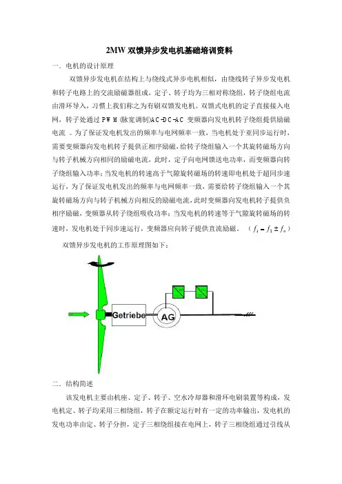
这种结构使得发电机对风速的变化更具有稳定性和高效性,适应了风能资源的变化。
2.双馈异步风力发电机机组的工作原理双馈异步风力发电机机组的工作原理是利用风机收集风能,并通过机械变速器将风机转子的旋转速度调整为适合发电机组的旋转速度,然后将发电机的输出交流电经过变流器转换为直流电,再通过变流器将直流电转换为符合电网要求的交流电。
在这一过程中,变流器起到了关键作用。
三、双馈异步风力发电机机组变流器基本运行原理1.变流器的功能双馈异步风力发电机机组的变流器是连接风力发电机和电网的关键设备,其主要功能是将发电机输出的交流电转换为符合电网要求的交流电。
在风能转换为电能的过程中扮演了至关重要的角色。
2.变流器的基本构造双馈异步风力发电机机组的变流器包含整流器、中间直流环节和逆变器三部分。
整流器主要将发电机输出的交流电转换为直流电,中间直流环节用于存储和平稳直流电的波动,逆变器则将直流电转换为符合电网要求的交流电。
3.变流器的工作原理变流器通过控制发电机输出的交流电的频率和电压,将其转换为符合电网要求的交流电。
变流器运用了现代电力电子技术,能够实现对发电机输出电流的精确调节,并且保证输出交流电的质量和稳定性。
在变流器的运行过程中,控制系统起到了关键的作用,通过对变流器工作状态的监测和控制,保证了发电机组的安全可靠运行。
国家科学技术进步奖推荐项目一一、项目名称2MW双馈式风电机组关键技术与规模化应用二、推荐单位意见该项目在形成了具有自主知识产权的双馈风电机组正向设计理论与技术体系、风电机组系统匹配与优化技术、高能量密度风电技术、风电自适应增功技术与抗恶劣环境风电技术等取得了一系列创新性风电整机设计方法与技术研究成果,打破了国外技术封锁,研制了高质量的2MW双馈式风电机组,并在提高产品竞争力,扩大风电应用市场取得突破。
项目开发的具有自主知识产权的2MW双馈式陆上风电机组涵盖三个风区、常/低温、内陆/沿海/高原等4大系列31种规格型号。
产品通过了国内外权威机构的测试认证,H93、H102机型风轮直径当时国内最大,H111、H120机型风轮直径当时国际最大,对风电加长叶片的发展作出了贡献。
项目申请专利95项(其中发明10项、PCT专利4项),授权39项;软件著作权8项;制定标准76项(国家标准3项)。
产品在国内华北、西北、西南等7大区域89座风电场安装运行2401台,并出口美国、巴基斯坦,在新疆、内蒙古、云南等区域发电小时数排名前茅。
近3年销售收入188.6亿元,利润5.1亿元。
2015年2MW风电机组新增装机量世界第十,市场份额逐年大幅提高。
项目相关内容获2015年度重庆市科技进步一等奖,2013年获得中船重工科技进步二三等奖各1项,2011年获中船重工科技进步一等奖1项,2009年获联合国蓝天奖。
目标产品获重庆市名牌产品和科技部优秀新产品称号,应用该产品的工程曾获中国电力工程优质奖。
推荐该项目为国家科学技术进步奖二等奖。
三、项目简介风力发电机是实现风能捕获、传递和转换的复杂高耸机电一体化系统,其运行工况复杂、连续工作20年、环境条件极端恶劣,涉及多学科交叉领域、技术难度极大。
在重庆市重大专项等项目支持下,在风电机组总体技术领域取得重大突破,极大的提高了风电机组的设计安全性、运行稳定性与可靠性,之后围绕开发具有市场竞争力的产品、扩大风电市场展开研发。
Design Study of Doubly-Fed Induction Generators for a 2MW Wind TurbineABSTRACTA design study for a 2 MW commercial wind turbine is presented to illustrate two connection methods for a standard doubly-fed induction machine which can extend the low speed range down to 80% ,slipping without an increase in the rating of the power electronic converter. This far exceeds the normal 30% lower limit. The low speed connection is known as induction generator mode and the machine is operated with a short circuited stator winding and with all power flow being through the rotor circuit. A two loop cascaded PI control scheme has been designed and tuned for each mode. The purpose of this paper is to present simulation results which illustrate the dynamic performance of the controller for both doubly-fed induction generator connection methods for a 2 MW wind turbine. A simple analysis of the rotor and the voltage for the doubly-fed connection method is included as this demonstrates the dominant components that need to be considered when designing such advanced control strategies.Keywords: Doubly-fed, Induction generator, Wind turbineLIST OF IMPORTANT SYMBOLSvrdq Direct and quadrature rotor voltageirdq Direct and quadrature rotor currentλsdq Direct and quadrature stator flux linkagePs Stator real powerQs Stator reactive powerpfs Stator power factorTe Torquep Differential operatorLm Magnetising reactanceRr Rotor resistanceLr Rotor reactanceσ Total leakage inductanceωsf Slip frequency‘s’ Stator referred‘r’ Rotor referred‘*’ Reference value1. INTRODUCTIONThere is continuing interest in wind turbines, especially those with a rated power of many megawatts.This popularity is largely driven by both environmental concerns and also the availability of fossil fuels. Legislation to encourage the reduction of the so called carbon footprint is currently in place and so interest in renewables is currently high. Wind turbines are still viewed as a well established technology that has developed from fixed speed wind turbines to the now popular variable speed technology based on doubly-fed induction generators (DFIGs). ADFIG wind turbine is variable speed with the rotor converter being controlled so that the rotor voltage phase and magnitude is adjusted to maintain the optimum torque and the necessary stator power factor . DFIG technology is currently well developed and is commonly used in wind turbines. The stator of a DFIG is directly connected to the grid with a power electronic rotor converter utilised between the rotor winding and the grid. The variable speed range is proportional to the rating of the rotor converter and so by limiting the speed range to ±30%the rotor converter need only be rated for 30% of the total DFIG power whilst enabling full control over the full generator output power. This can result in significant cost savings for the rotor converter . The slip ring connection to the rotor winding however must be maintained for reliable performance.The power – generator speed characteristic shown in figure 1 is a fora commercial 2MW wind turbine.The generator speed varies with wind speed,however this relation is set for a specific location. As wind speed, and therefore machine speed, falls the power output of the generator reduces until the wind turbine is switched off when the power extracted from the wind is less than the losses of the generator and converter. An operating mode has been proposed by a wind turbine manufacturer that is claimed to extend the speed range so that at lower speed the power extracted from the wind is greater than the losses in the system and so the system can remain connected. This proposed that the standard doubly-fed (DF) connection is used over the normal DF speed range and the so-called induction generator (IG) mode is used to extend the low speed operation. Previous work has illustrated that IG mode enables the DFIG to operate down to 80% slip . This change in operation is achieved by disconnecting the stator from the grid in DF mode and then short circuiting the stator to enable IG operation. All of thegenerator power flows through the rotor converter in IG mode. The IG curve is identical to the DF curve for ±30% slip. The estimated IG power extracted from the wind at low speeds is obtained by extrapolating the curve for the DF mode.The reference torque required by both controllers (DF and IG mode) can easily be derived from this curve. The torque – speed data can then be stored in a look-up table so the reference torque is automatically varied with speed.The capability of modern DF wind turbines to vary the reactive power absorbed or generated ,allows a wind turbine to participate in the reactive power balance of the grid.The objective of this paper is to investigate the controller performance of DF and IG mode for a 2MW, 690V, 4-pole DFIG using machine parameters provided by the manufacturer. This is further research building on a previous paper which demonstrated the steady-state performance of the two modes of operation, DF and IG mode . The authors discussed the steady-state efficiency for both connections. The steady-state performance work illustrated that there were benefits to operating the machine in one connection method as opposed to the other.This paper examines the controllability (i.e. transient performance) of the 2 MW wind turbine. Results of the full dynamic controller (current regulation, decoupling equations and vector control) in both DF mode and IG mode are shown. A detailed analysis of thecomponents that form the rotor voltage over the full operating,range in DFIG mode is presented ,as this enables the dominant control components to be identified. This is particularly important when designing advanced control schemes as an overview over the full operating range can be identified. Simulation models, which have been validated against a 7.5kW laboratory rig are applied to a realistic 2 MW wind turbine to enable conclusions to be made regarding the proposed use of IG mode in a real wind turbine2. CONNECTION METHODSThe grid side inverter (GSI) is controlled to maintain a fixed dc link voltage with a given power factor at the grid . The rotor side inverter (RSI) is controlled so the maximum energy is extracted from the kinetic energy of the wind whilst enabling the stator power factor to be controlled within the limits of the grid requirements though unity power factor is often desirable.The GSI is controlled as in DF mode. The objective of the RSI is to control the stator flux linkage while extracting the maximum power from the kinetic wind energy.3. CONTROLLER PERFORMANCEA closed loop controller for both DF mode and IG mode has been discussed in prior work but only for a 7.5 kW laboratory test rig. The dynamics of a 2 MW system are somewhat different and are investigated in this paper. The performance of the dynamic controller for both DF and IG mode are shown in this section for a 2 MW wind turbine.3.1. DFIG Mode (T and Q Control)The reference values for the controller in DF mode are torque (see figure 1) and stator reactive power to enable the grid code requirement to be achieved. Two speedsare investigated in this section to enable the performance of the controller to be shown both above and below the 20% of rated power limit from the grid code requirements.A nominal generated power of 320 kW is achieved at 1150 rpm (less than 20% of rated power) and a nominal power of 125 KW is achieved at 1550 rpm (greater than 20% of the rated power). The reference and actual torque, Te, and stator reactive power, Qs, are shown for both speeds in figure 5.The value of reference torque, Te*, for both speeds is the specific nominal torque for a given speed calculated from figure 1; 2672 Nm for 1150 rpm and 7701 Nm for 1550 rpm. A step of 200 Nm is applied at both speeds to illustrate the dynamic response to a step change in torque. The value of reference stator reactive power, Qs*, at 1150 rpm is varied between the limits specified by the grid code requirements; initially 5% of the generated power with a step at t=3.5s to +5% of the generated power. At 1550 rpm the stator power factor, pfs*, is initially 0.95 leading with a step change at t=3s to unity pfs and a final step at t=4s to a 0.95 lagging pfs. The vector control loops are tuned for a time constant of 0.1s and 0.9s for the Te and the Qs loops respectively. The vector control is designed to have a slower bandwidth than the current regulation.The actual rotor current direct, irds, and quadrature, irqs, components corresponding to figure 5 are shown in figure6. The effect of the step change in Te* is appa rent on the irqs (the superscript ‘s’ indicates that the variable is referred to the stator) as expected. The irqs* component at 1550 rpm contains small transient responses at t=3s and t=4s that are due to the step changes in the Qs value. The step change in Qs*, shown in figure 5, causes a fast change in irds*, figure 6, as there is initially an error between the reference and actual Qs as the control takes a short while to respond. The current regulation is tuned to ensure that the bandwidth prevents the controller responding to such transients while still achieving a suitable speed of response.The equation based tuning used to design the controller gives similar values of proportional and integral gains for the current regulation direct and quadrature loops to those used by Holdsworth et al.3.2. IG Mode (T and Flux Control)The reference values for the controller in IG mode are stator flux linkage and torque. Two conditions are investigated for the 2 MW generator in IG mode, start-up and torque step responses, at 400 rpm (minimum IG mode speed ) and 1420 rpm (generated power at this speed corresponds to the upper power rating of rotor converter, 600 kW).The steady-state Te is the nominal value for the speed of operation, 320 Nm for 400 rpm and 4081 Nm for 1420 rpm derived from figure 1. A start-up sequence is required to establish the rated λsr in the machine, for a given speed, by means of a ramp, before the machine can generate power.Once the controller reference λsr has been established in the machine, the Te* is increased by means of a controlled ramp to the nominal value for a given speed and then a step response of 50 Nm step at 400 rpm and 200 Nm at 1420 rpm is applied. The controller regulates the machine to track Te* as expected.The vector control loops determine the reference rotor current values that are shown in figure 8. The ird component initially increases rapidly to establish the λsr and is approximately 3 times the nominal steady-state value for a given load point. The current is within the rated limit at all times. The initial ird can be significantly reduced if a slower response of λsr is implemented.The irq component is regulated by the torque loop to enable the desired power to be generated. Initially there is a slight error due to the high ird which affects the quadrature loop by the cross coupling terms. Once nominal λsr is established in the machine the direct and quadrature loops are decoupled. Again a Te step causes a transient spike in irq* though the control is tuned to be slower than this change in reference value.4. CONTRIBUTION OF ROTOR VOLTAGE COMPONENTSThe performance of both DF and IG mode has been illustrated in the previous section. Both controllers are based on an inner current loop and an outer control loop for torque and stator reactive power in the DF case and torque and stator flux linkage in the IG case. Decoupling equations were then added to the PI controller outputs to reduce the effect of cross coupling between the loops. The final part of this work studies the contribution of the steady state components of rotor voltage, given in full in eqns for a 2 MW machine to assess the importance of decoupling equations at various speeds. The rotor voltage, vrs, rotor current,irs, and the non-differential components of vrs given by eqns are investigated for the full DF speed range (1000 to 1950 rpm) with the nominal torque determined from figure 1, and a stator power factor, pfs, range of 0.9 lagging to 0.9 leading. Only the pfs is considered as the GSI is assumed to maintain unity pf at the rotor converter connection to the grid independent of the RSI.5. CONCLUSIONSThis paper has investigated the controller response for the DF and IG mode connections for a 2 MW DFIG wind turbine. The machine parameters for the 2 MW machine were provided, for a commercially available WRIM used in wind turbines,by the manufacturer. The 2 MW machine parameters used in this work are not simply a linear scaling of prior work on a 7.5 kW machine and so the characteristics are not identical between the two machines.Two areas of analysis have been investigated with respect to the 2 MW DFIG. Existing simulation models have been used to evaluate the controllability and steady-state and transient behaviour of a 2 MW DFIG in DF and IG mode.The outcome shows that IG mode is a controllable mode of operation which will extend the low speed operation as rotor voltage decreases (as speed reduces) and so the voltage limit of the IGBTs will be respected as the current and power limits of the machine and converter. The composition of the rotor voltage was investigated in DF mode for the 2 MW DFIG. This showed how the importance of the decoupling equations on the performance of the DFIG varied with speed. ACKNOWLEDGEMENTSThe authors are grateful to and the for their support.REFERENCES1. Pena R, Clare J and Asher GM. The Application Of Doubly Fed Induction Generator to Variable-Speed Wind-Energy Generation. May 1996;2. Kelber C and Schumacher W. Control of Doubly-Fed Induction Machines as an Adjustable Speed Motor/Generator.3. Ran L, Bumby JR and Tavner PJ. Use of Turbine Inertia for Power Smoothing of Wind Turbines with a DFIG.. March 20044. Müller S, Deicke M and De Doncker RW. Doubly fed induction generator systems for wind turbines. .5. Hansen AD, Iov F, Blaaberg F and Hansen LH. Review of Contemporary Wind Turbine Concepts and their Market Penetration. Wind Engineering 2004;6. Chengwu L and Fengxiang W and Yong T. Design and Implementation of A Doubly- Fed Wind Power Control System. International Conference on Power System Technology: PowerCon 2002;。