BF系列伸缩器使用说明书
- 格式:docx
- 大小:30.49 KB
- 文档页数:5
双法兰传力伸缩节的使用方法双法兰传力伸缩节是一种用于管道连接的装置,其主要作用是连接两个法兰之间的管道,并在管道输送过程中承受由于压力和热胀冷缩引起的应力位移。
在使用双法兰传力伸缩节前,需要考虑以下几个因素:1. 接口前处理在安装双法兰传力伸缩节之前,需要安装法兰并将凸缘连接好,法兰的大小和型号需要与管道相符合。
在连接法兰时,需确认法兰的连接面平整,无任何杂物和污垢。
2. 安装传力伸缩节将传力伸缩节放到法兰上,调整传力伸缩节的长度合适,一端与一个法兰连接起来,确保两端的螺栓和螺母松散。
将另一端的法兰对齐管道,再紧密螺紧螺栓和螺母。
3. 注意事项在安装双法兰传力伸缩节时,需要注意以下几点:(1)确认安装的方向正确,避免造成设备损坏或者意外事故的发生;(2)管道需在没有任何应力的情况下运输和安装,避免对传力伸缩节造成不必要的压力;(3)在使用过程中,如果出现管壳破裂的问题,应该立即停止使用,检查问题后再继续使用。
4. 保养维护在使用双法兰传力伸缩节时,需要定期进行检查和维护。
检查时需要关注法兰和管道的连接状态,确认连接是否紧密,并检查传力伸缩节的长度是否与使用时一致。
另外,应该对管道进行清洁和维护,防止因管道中的腐蚀、污垢等影响传力伸缩节的使用寿命。
5. 结束使用当传力伸缩节出现损坏、老化或达到使用寿命时,需要及时更换。
更换时需要先停止管道输送,拆除传力伸缩节并清理管道,更换新的传力伸缩节,并按照上述步骤进行安装和维护。
总之,双法兰传力伸缩节是一种重要的管道连接装置,使用时需要注意安装方向、安装位置和安装维护等问题,并且需要建立正常的保养和维护制度,以保证传力伸缩节的正常使用寿命。
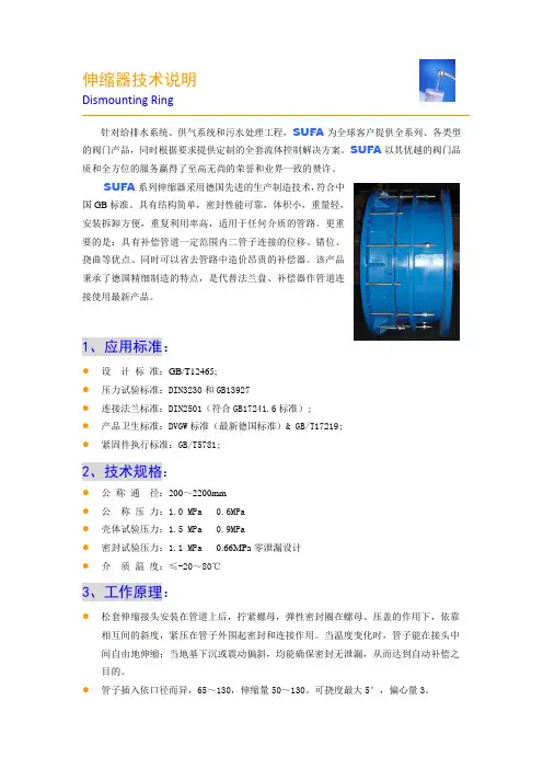
伸缩器技术说明Dismounting Ring针对给排水系统、供气系统和污水处理工程,SUFA为全球客户提供全系列、各类型的阀门产品,同时根据要求提供定制的全套流体控制解决方案。
SUFA以其优越的阀门品质和全方位的服务赢得了至高无尚的荣誉和业界一致的赞许。
SUFA系列伸缩器采用德国先进的生产制造技术,符合中国GB标准。
具有结构简单,密封性能可靠,体积小,重量轻,安装拆卸方便,重复利用率高,适用于任何介质的管路。
更重要的是:具有补偿管道一定范围内二管子连接的位移、错位、挠曲等优点、同时可以省去管路中造价昂贵的补偿器。
该产品秉承了德国精细制造的特点,是代替法兰盘、补偿器作管道连接使用最新产品。
1、应用标准:●设计标准:GB/T12465;●压力试验标准:DIN3230和GB13927●连接法兰标准:DIN2501(符合GB17241.6标准);●产品卫生标准:DVGW标准(最新德国标准)& GB/T17219;●紧固件执行标准:GB/T5781;2、技术规格:●公称通径:200~2200mm●公称压力:1.0 MPa 0.6MPa●壳体试验压力:1.5 MPa 0.9MPa●密封试验压力:1.1 MPa0.66MPa零泄漏设计●介质温度:≤-20~80℃3、工作原理:●松套伸缩接头安装在管道上后,拧紧螺母,弹性密封圈在螺母、压盖的作用下,依靠相互间的斜度,紧压在管子外围起密封和连接作用。
当温度变化时,管子能在接头中间自由地伸缩;当地基下沉或震动偏斜,均能确保密封无泄漏,从而达到自动补偿之目的。
●管子插入依口径而异,65~130,伸缩量50~130。
可挠度最大5°,偏心量3。
●主要用于闸阀、蝶阀、止回阀、球阀、截止阀等各种阀门及各种设备与管子的连接。
介质水、油、气等。
4、材质选用:●本体及压盖采用整体浇铸式结构,树酯砂铸造。
材质球墨铸铁GGG50,符合DIN1693要求,强度大于500MPa,延伸率大于10。
HALLIBURTON伸缩节技术规程一、伸缩节结构:它由上接头、伸缩外筒、剪切套、滑动芯轴、芯轴密封支撑(12个)、V型圈(6个)、密封挤压环、止退销(4+4)、剪切销(5个)和变扣短节组成。
二、拆卸保养步骤:1、将伸缩节外筒中部夹在虎钳上,用内六方扳手分别将外筒上下端的各4只止退螺钉卸下。
再用平口螺丝刀从剪切套上卸下6只剪切销钉。
2、被钳打在外筒上部的凹槽处,将上接头卸掉取下。
清洗并擦干净,更换密封圈,均匀涂好密封脂。
3、被钳打在芯轴下部,将变扣短节从芯轴卸掉取下。
4、被钳打在外筒下部的凹槽处,将剪切套卸掉(注意打管钳的位置应避开销钉孔),从芯轴下部取下,5、用手将变扣短节从芯轴下部拧上,再用木块垫在芯轴下端,用榔头向上敲击,使芯轴密封套滑出外筒,拧掉变扣短节,将芯轴从外筒上部取出。
6、被钳打在芯轴中部,将密封挤压环卸下,更换两组V型密封圈和密封支撑(唇部相向)。
上紧密封压环,用锉刀将上下管钳打过部位的毛刺挫平,并用干净棉纱将整个芯轴外表面擦干净,均匀涂好密封脂。
7、用软棉布清洗伸缩节外筒的内表面,并竖直放置,将其筒内的清洗油控出。
(注意:切勿用硬物通洗内表面,以防滑伤其密封面)8、拆卸完毕。
三、组装步骤:1、将伸缩节外筒中部夹在虎钳上,从其上部将密封芯轴插入,当芯轴密封套进入外筒时,用铜棒从上部敲击芯轴,使芯轴下端滑出外筒到相应位置。
2、将剪切套公扣处均匀涂好润滑脂,并从芯轴下部套入,与外筒下部母扣连接(注意打管钳的位置应避开销钉孔),丝扣上满后将4只止退螺钉从外筒螺钉孔分别上紧。
3、将剪切套销钉孔与密封芯轴销钉孔对正,从剪切套外部分别将6只剪切销钉上紧固定(注意:密封芯轴的剪切销钉孔有上中下3个位置,分别适应不同井况的要求。
现场可根据实际需要进行调整,工房保养时应将销钉锁定在下部位置)。
4、被钳打在密封芯轴下部,清洗并检查FOX公母扣及密封部分是否完好,擦干净后均匀涂好润滑脂,将变扣短节按规定扭距上紧。
VSSJ‐C2F‐6C型双法兰连接传力伸缩接头使用说明书铁岭市求精阀门厂二○一三年四月目 录1.主要用途2.结构特点3.执行标准4.工作原理、主要结构、外形及连接尺寸5.主要零部件材料6.保管、安装及使用7.注意事项8.通讯方式1.主要用途伸缩节是管线连接的常用且必须的附件。
本系列伸缩节主要用于介质温度≤80℃的输水管路上,安装在阀门或者其它设备的一侧,用于方便阀门或设备的拆卸和维修。
2.结构特点2.1法兰连接,结构简单,调整灵活,安装方便;2.2对于上下游管道的错位、偏角有一定的补偿作用;2.3伸缩量可根据用户的要求灵活设计,节省安装空间,降低设备成本;2.4各个零部件采用不同的材料配置即可产生多种组合,适应不同用户要求。
3.性能规范双 法 兰 伸 缩 节 性 能 规 范公称压力 0.25 0.6 1.0 1.6 2.5 4.0 MPa试验压力 强度 0.375 0.90 1.50 2.40 3.75 6.00温度常温 密封 0.300 0.75 1.25 2.00 3.00 5.00 常温工作压力(MPa)P80.250 0.60 1.00 1.60 2.50 4.00 ≤80℃ 适用介质 水、海水、油品适用温度 ≤80℃4.执行标准4.1设计制造按照GB/T 12465‐2000标准;4.2法兰连接按照GB/T 9113.1‐2000标准;4.3压力试验按照GB/T 13927‐2008标准。
5.主要结构、工作原理、外形及连接尺寸5.1主要结构:本伸缩节由法兰管、密封圈、法兰压盖、贯通螺柱、螺母、伸缩管、压盖螺柱、压盖螺母等组成。
如图1.5.2工作原理:本伸缩节一般安装在阀门(或其它设备)的上游侧。
即伸缩节的上游为管道法兰,下游为阀门。
本伸缩节的贯通螺柱分别深过管道配对法兰和阀门配对法兰的背面,通过螺母,实现上下游管道和阀门设备的对接。
需要拆卸阀门时,先把贯通螺柱无方头端(法兰管一侧)的配对法兰背后的螺母松开,再将伸缩管一侧的螺母向法兰管方向松开,然后固定贯通螺柱的方头,旋转伸缩管配对法兰背面的螺母,使法兰管端向伸缩管端移动。
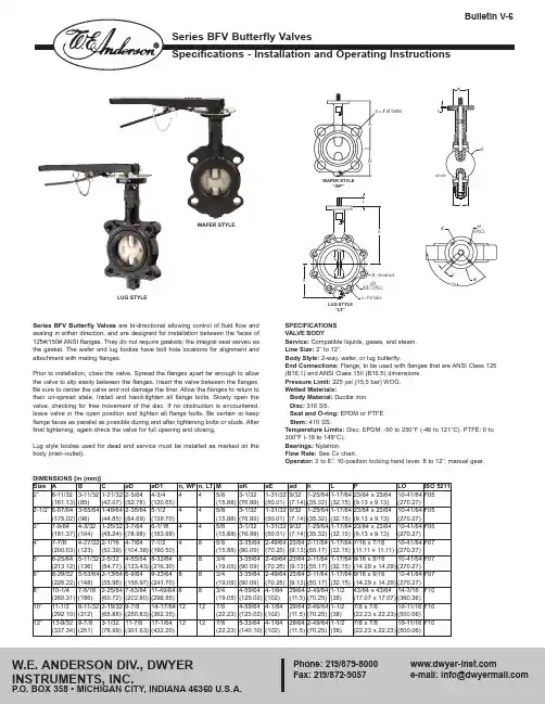
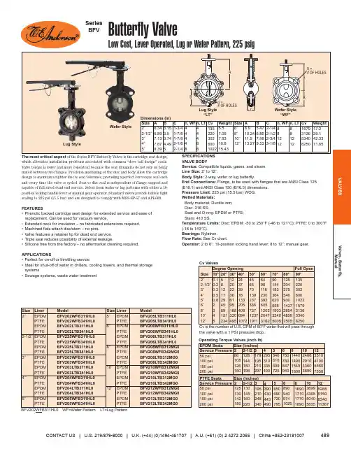
SPECIFICATIONS VALVE BODYService: Compatible liquids, gases, and steam.Line Size: 2˝ to 12˝.Body Style: 2-way, wafer, or lug butterfly.End Connections: Flange, to be used with flanges that are ANSI Class 125(B16.1) and ANSI Class 150 (B16.5) dimensions.Pressure Limit: 225 psi (15.5 bar) WOG.Wetted Materials:Body Material: Ductile iron.Disc: 316 SS.Seat and O-ring: EPDM or PTFE.Stem: 410 SS.Temperature Limits: Disc: EPDM: -50 to 250°F (-46 to 121°C). PTFE: 0 to 300°F (-18 to 149°C).Bearings: Nylatron.Flow Rate: See Cv chart.Operator: 2 to 6˝: 10-position locking hand lever. 8 to 12˝: manual gear.Series BFV Butterfly Valves are bi-directional allowing control of fluid flow and sealing in either direction, and are designed for installation between the faces of 125#/150# ANSI flanges. They do not require gaskets; the integral seat serves as the gasket. The wafer and lug bodies have bolt hole locations for alignment and attachment with mating flanges.Prior to installation, close the valve. Spread the flanges apart far enough to allow the valve to slip easily between the flanges. Insert the valve between the flanges.Be sure to center the valve and not damage the liner. Allow the flanges to return to their un-spread state. Install and hand-tighten all flange bolts. Slowly open the valve, checking for free movement of the disc. If no obstruction is encountered,leave valve in the open position and tighten all flange bolts. Be certain to keep flange faces as parallel as possible during and after tightening bolts or studs. After final tightening, again check the valve for full opening and closing.Lug style bodies used for dead end service must be installed as marked on the body (inlet–outlet).Size 2˝2-1/2˝3˝4˝5˝6˝8˝10˝12˝A6-11/32(161.13)6-57/64(175.02)7-9/64(181.37)7-7/8(200.03)8-25/64(213.12)8-29/32(226.22)10-1/4(260.31)11-1/2(292.10)13-9/32(337.34)B 3-11/32(85)3-55/64(98)4-3/32(104)4-27/32(123)5-11/32(136)5-53/64(148)7-5/16(186)8-11/32(212)9-7/8(251)C 1-21/32(42.07)1-49/64(44.85)1-25/32(45.24)2-1/16(52.39)2-5/32(54.77)2-13/64(55.96)2-25/64(60.72)2-19/32(65.88)3-1/32(76.99)øD 2-5/64(52.78)2-35/64(64.69)3-7/64(78.98)4-7/64(104.38)4-55/64(123.43)6-9/64(155.97)7-63/64(202.80)9-7/8(250.83)11-7/8(301.63)øD14-3/4(120.65)5-1/2(139.70)6-1/16(153.99)7-1/2(190.50)8-33/64(216.30)9-33/64(241.70)11-49/64(298.85)14-17/64(362.35)17-1/64(432.20)n, WF 44448881212DIMENSIONS [in (mm)]WAFER STYLELUG STYLELUG STYLE“LT”M 5/8(15.88)5/8(15.88)5/8(15.88)5/8(15.88)3/4(19.05)3/4(19.05)3/4(19.05)7/8(22.23)7/8(22.23)øK 3-1/32(76.99)3-1/32(76.99)3-1/32(76.99)3-35/64(90.09)3-35/64(90.09)3-35/64(90.09)4-59/64(125.02)4-59/64(125.02)5-33/64(140.10)øE1-31/32(50.01)1-31/32(50.01)1-31/32(50.01)2-49/64(70.25)2-49/64(70.25)2-49/64(70.25)4-1/64(102)4-1/64(102)4-1/64(102)ød9/32(7.14)9/32(7.14)9/32(7.14)23/64(9.13)23/64(9.13)23/64(9.13)29/64(11.5)29/64(11.5)29/64(11.5)h 1-25/64(35.32)1-25/64(35.32)1-25/64(35.32)2-11/64(55.17)2-11/64(55.17)2-11/64(55.17)2-49/64(70.25)2-49/64(70.25)2-49/64(70.25)L1-17/64(32.15)1-17/64(32.15)1-17/64(32.15)1-17/64(32.15)1-17/64(32.15)1-17/64(32.15)1-1/2(38)1-1/2(38)1-1/2(38)P23/64 x 23/64(9.13 x 9.13)23/64 x 23/64(9.13 x 9.13)23/64 x 23/64(9.13 x 9.13)7/16 x 7/16(11.11 x 11.11)9/16 x 9/16(14.29 x 14.29)9/16 x 9/16(14.29 x 14.29)43/64 x 43/64(17.07 x 17.07)7/8 x 7/8(22.23 x 22.23)7/8 x 7/8(22.23 x 22.23)LO 10-41/64(270.27)10-41/64(270.27)10-41/64(270.27)10-41/64(270.27)10-41/64(270.27)10-41/64(270.27)14-3/16(360.36)19-11/16(500.06)19-11/16(500.06)ISO 5211F05F05F05F07F07F07F10F10F10n, LT 44488881212122-1/27/8-9UNC51-3/43/4-10UNC VALVE DISASSEMBLY1.After removal of valve from the piping system, open the valve fully;2.Remove the handle or actuator;3.Remove the stem retaining pins;4.Pull out the upper stem;5.Pull out the bottom stem;6.Remove the disc from the liner. Do not damage the disc edge;7.Remove the liner;8.If the valve has bushings and o-rings, remove by tapping with blunt instrument;9.Inspect all components for wear and replace as required.VALVE ASSEMBLY1.Clean all reusable parts;2.If valve has bushings and o-rings, tap them carefully;3.Apply a lubricant or soapy solution compatible with elastomers to facilitateassembly;4.Insert liner into body by pressing it into the body evenly;5.Insert disc in open position into liner. Make certain broached end of disc is atthe upper stem end of the body;6.Coat the upper stem with a general purpose lubricant & install into body;7.Install bottom stem;8.Install retaining pins to both stems;9.Install the operator;10.Check assembly by opening & closing the valve several times;11.Follow installation instructions for reinstalling the valve in the piping system.MAINTENANCENo regular maintenance or lubrication is required.WARRANTYThe Series BFV Butterfly Valve is warranted from defects in materials and workmanship for (1) year from the date of purchase. In the unlikely event the valve should fail, the unit can be returned to the factory for warranty repair if the warranty period has not expired. Contact our customer service department for an RGA number and to set up the return.EPDM SeatsService Pressure 50 psi 100 psi 150 psi 200 psi PTFE SeatsService Pressure 50 psi 100 psi 150 psi 200 psiSize (inches)Size (inches)2861081261502-1/212614415019831791952102974295310335400554061069972567507808479408144014901549180010246629103360389012351041005560755821251301421802-1/213014516022031952102483404390430443490565069072079568909409741020816901710177018901036994365504058351252656150834011367DEGREE OPENINGSize 2˝2-1/2˝3˝4˝5˝6˝8˝10˝12˝10°0.10.20.30.50.8234520°58121729458915123430°12202236619518832049540°24373978133205408694107250°4565701392373667271237191160°649811623039260512022047316270°90144183364620958190332405005FULL OPEN 90°1352203026001022157931365340825080°1252042755469301437285448597505Cv is the number of U.S. GPM of 60°F water that will pass through the valve with a 1 PSI pressure drop.Cv VALUESBREAK TORQUES IN INCH-POUNDSFIGURE 1Size LO 2˝10-41/64(270.27)2-1/2˝10-41/64(270.27)3˝10-41/64(270.27)4˝10-41/64(270.27)5˝10-41/64(270.27)6˝10-41/64(270.27)Size 8˝-10˝12˝A2-61/64(75)3-13/64(81.36)B2-31/64(63.10)3-5/32(80.17)Ø11-13/16(300.04)11-13/16(300.04)g12-49/64(70.25)2-49/64(70.25)h11/8(3.18)1/8(3.18)C3-63/64(101.20)4-21/32(118.27)E2-61/64(75)3-13/64(81.36)F9-27/32(250.03)8-15/16(227.01)G3-25/64(86.12)3-9/32(83.34)DIM B D Valve Size (inches)21-1/25/8-11UNC 2-1/21-1/25/8-11UNC 31-1/25/8-11UNC 41-3/45/8-11UNC 623/4-10UNC823/4-10UNC 102-1/47/8-9UNC LUG RECOMMENDED FLANGE BOLT LENGTHS (Fig. 1)HAND LEVER DIMENSIONS [in (mm)]MANUAL GEAR DIMENSIONS [in (mm)]©Copyright 2014 Dwyer Instruments, Inc.Printed in U.S.A. 9/14FR# RV-440860-50 Rev. 2。

BF型防坠器使用维护说明书一、简介1.用途:防坠器是竖井罐笼的一种重要安全装置。
在提升过程中,由于某种原因,提升钢丝绳断绳或连接装置断裂,它能自动抓住制动绳,使罐笼平稳停住,不致坠入井底,从而保证人员的安全和提升设备不致损坏。
2.主要技术特征3.防坠器的构造及其作用:该防坠器在结构上主要由安装在罐笼上的抓捕器、井架上的缓冲器、井底水窝内的拉紧装置以及制动绳、缓冲绳和连接此二绳的连接器组成(见图一)。
(1)抓捕器抓捕器的主要作用是当提升钢丝绳断绳时,它能自动动作,并安全可靠地抓住制动绳,使断绳后的罐笼停住在制动绳上。
如图2所示。
(2)钢丝绳螺旋缓冲器该缓冲器是利用缓冲绳通过缓冲器时的弯曲变形阻力和摩擦阻力所作的功来抵消下坠罐笼的动能。
其主要作用是断绳时,抓捕器抓住制动绳后,使下坠的罐笼能在规定的减速度范围内滑行一段距离,然后平稳的停住,以确保乘罐人员的身体健康。
如图3所示。
缓冲器布置参数尺寸如图6所示。
(3)制动绳、缓冲绳连接器连接器是制动绳与缓冲绳接头处的连接装置,能把制动绳所承受的外力传递给缓冲器。
如图4所示。
拉紧装置是将制动绳固定在固定梁上,通过紧度限制器的制动螺栓,使其有一定的张力。
如图5所示。
拉紧装置布置参数尺寸如图7所示。
图1 防坠器布置图图2 BF型抓捕器图3 缓冲器1-螺杆;2-小轴;3-滑块;4-外壳;5-密封;6-缓冲钢丝绳;7-螺母;8-夹紧螺栓;9-壁板;图4 单绳连接器1-半连接器;2-连接螺母;3-杯形体;4-锥形体;5-麻屑;6-特殊合金;7-制动钢绳;8-缓冲钢绳。
BF 型缓冲器安装参数表序 号 代 号 名称单位型 号111112 122 152 321 1 A 两制动绳中心距 mm 1116 1394 1116 1290 1556 2 B 缓冲器底座横向 mm 230 230 230 230 230 图5 拉紧装置紧度限制器:1-绳卡;2-角钢;3-制动螺栓; 拉 紧 箍:4-固定梁;5-压板;6-拉紧螺母;7-拉紧螺栓;8-制动绳。

双法兰限位伸缩接头-
技术说明
1、B2F(VSSJA-2)型双法兰松套限位伸缩接头(外型图)
2、本厂生产的伸缩接头的工作压力为1.0MPa,设计制作均符合GB/T12465--2007。
标准。
出厂均有严格的检验手段,能满足各种运行工况在水泵校验等状况下不会产生纵向位移。
法兰符合GB/T9115-2000标准。
3、产品特点:
(1)本次合同生产伸缩接头:本体,短管、螺柱、采用Q235,;密封圈采用丁晴橡胶;压盖、螺母等均采用Q235材质。
(2)由于同一类型的全部伸缩接头均为本厂生产,毛坯统一订货,同一型号伸缩接头的零部件,易损件均能互换。
伸缩接头醒目处均注明闸门型号、口径、工作压力。
4、主要产品结构尺寸表:
限位伸缩接头主要由松套伸缩接头和限位短管等构件组成。
它能防止管道因超量位移导致补偿接头的泄漏或损坏。
主要用于在允许位移范围内吸收轴向位移和承受压力推力的管道松套连接。
1—本体 2—密封圈 3—压盘 4—限位螺杆 5—螺母 6—限位短管 7—螺柱
双法兰松套限位伸缩接头
尺寸连接表
公称通径管子外径外形尺寸
伸缩量
法兰连接尺寸Dw L L1
0.6MPa 1.0MPa
D D1 n-d。
D D1 n-d。
65 76
340 105 50
160 130 4-¢14 185 145 4-¢18 80 89 190 150 4-¢18 200 160 8-¢18。
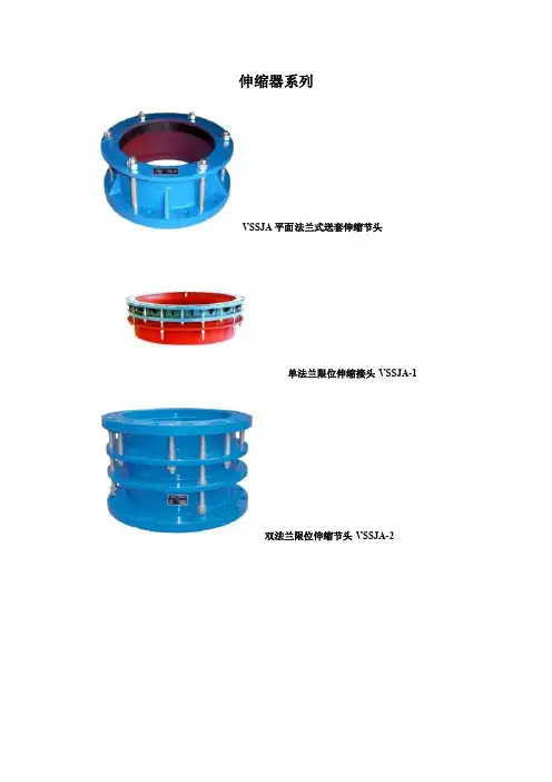
伸缩器系列VSSJA平面法兰式送套伸缩节头单法兰限位伸缩接头VSSJA-1双法兰限位伸缩节头VSSJA-2VSSJAF双法兰传力伸缩接头VSSJAFG单法兰传力伸缩接头SSJB压盖式伸缩接头波纹补偿器SQ4G双盘伸缩器GJQ橡胶伸缩器型号编制说明工作原理及用途松套伸缩接头安装在管道上以后,拧紧螺母,弹性密封圈在螺母、压盖的压力下,依靠相互间的斜度,紧压在管子外围起密封和链接作用。
当温度变化时,管子能在接头中间自由地伸缩,当地基下沉,船舶振动偏斜,它均能确保密封无渗漏,从而达到自动补偿的目的。
VSSJA系列VSSJA平面法兰式送套伸缩节头VSSJA结构图单法兰限位伸缩接头VSSJA-1VSSJA-1结构图双法兰限位伸缩节头VSSJA-2VSSJA-2结构图用途VSSJA型可广泛与蝶阀、闸阀、止回阀、截止阀等配套使用,可降低工程费用能有效解决阀门装卸困难。
主要用于管道与阀门链接,带有限位螺栓,可防止管道在外部作用力及热胀冷缩引起的内部作用较大时,拉脱伸缩接头,造成不必要的管道泄漏事故。
主要部件表主要结构尺寸传力伸缩接头作用及用途该接头能把因自然条件或工作条件造成的管道轴向推力和拉应力,通过螺栓从管道的这一端传递到整个管道,使应力分撒,避免造成管道设备的损坏。
VSSJAFG单法兰传力伸缩接头VSSJAFG结构图VSSJAF双法兰传力伸缩接头VSSJAF结构图主要部件表双盘伸缩器产品性能及用途该伸缩接头采用国标制造,重量轻,补偿量大,结构简单新一代伸缩器,它能有效的补偿管道因热胀冷缩造成的管道位移和折扣。
并能和各种阀门配套使用,使阀门装卸更便捷,使管线运行更安全、可靠,也可根据需要增加限位或防拉脱螺栓。
双盘伸缩器SQ4GSQ4G结构图主要部件表主要结构尺寸橡胶伸缩器GJQ型可曲绕橡胶接头又叫减震器、软接头等。
该产品是金属管道的柔性联接器,由内胶层、棉纶帘子布增强、外胶层复合的橡胶球体和松套金属法兰组成。
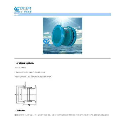
伸缩器一、产品[伸缩器 ]的详细资料:产品名称:伸缩器产品特点:法兰式管道伸缩器,管道伸缩器,伸缩器伸缩器的详细资料:法兰式管道伸缩器,管道伸缩器,伸缩器二、用途及特点:TSX管道伸缩器(又名伸缩节),在一定范围内可轴向伸缩,也能在一定的角度范围内克服管道对接不同轴而产生的偏移,本产品用于管道不需要温度补偿,只作拆卸阀门用,配装限位螺栓可以限位。
三、采用标准:法兰连接尺寸:GB/T9113.1-2000; GB/T9115.1-2000; JB78压力试验:GB/T13927-1992; JB/T9092-1999四、主要技术参数:公称通径0.6MPa 1.0MPa 1.6MPa 2.5MPa 公称压力0.9MPa 1.5MPa 2.4MPa 3.75MPa 试验压力Ps(MPa) 0.66MPa 1.1MPa 1.76MPa 2.75MPa 适用温度-29~125℃特殊适用介质淡水、海水、污水及轻质油品等五、主要零件的材质:零件名称材料器体铸铁、铸钢、不锈钢器管铸铁、铸钢、不锈钢密封丁晴橡胶、氯丁橡胶、乙丙橡胶、硅橡胶、氟橡胶六、伸缩器SX-6/10 连接尺寸:连接尺寸(标准值) 结构长度 (标准值) 公称通径0.6MPa 1.0MPa最长最短毫米英寸 D D1 D2 Z-Фd D D1 D2 Z-Фd80 3 190 150 124 4-18 200 160 132 8-18 252 202100 4 210 170 144 4-18 220 180 156 8-18 252 202 125 5 240 200 174 8-18 250 210 184 8-18 269 202 150 6 265 225 199 8-18 285 240 211 8-22 261 202 200 8 320 280 254 8-18 340 295 266 8-22 306 246 250 10 375 335 309 12-18 395 350 319 12-22 311 251 300 12 440 395 363 12-22 445 400 370 12-22 313 253 350 14 490 445 413 12-22 505 460 429 16-22 327 267 400 16 540 495 463 16-22 565 515 480 16-26 341 271 450 18 595 550 518 16-22 615 565 530 20-26 341 271 500 20 645 600 568 20-22 670 620 582 20-26 351 281 600 24 755 705 667 20-26 780 725 682 20-30 380 310700 28 860 810 772 24-26 895 840 794 24-30 420 350 800 32 975 920 878 24-30 1015 950 901 24-33 462 387 900 36 1075 1020 978 24-30 1115 1050 1001 28-33 478 403 1000 40 1175 1120 1078 28-30 1230 1160 1112 28-36 500 425 1200 48 1405 1340 1295 32-33 1455 1380 1328 32-39 464 374 1400 56 1630 1560 1510 36-36 1675 1590 1530 36-42 479 389七、伸缩器TSX-6/25 连接尺寸:连接尺寸(标准值) 结构长度 (标准值) 公称通径0.6MPa 1.0MPa最长最短毫米英寸 D D1 D2 Z-Фd D D1 D2 Z-Фd80 3 200 160 132 8-18 200 160 132 8-18 252 202100 4 220 180 156 8-18 235 190 156 8-22 252 202 125 5 250 210 184 8-18 270 220 184 8-26 259 202 150 6 285 240 211 8-22 300 250 211 8-26 261 202 200 8 340 295 266 12-22 360 310 274 12-26 306 246 250 10 405 355 319 12-26 425 370 330 12-30 311 251 300 12 460 410 370 12-26 485 430 387 16-30 313 253 350 14 520 470 429 16-26 555 490 448 16-33 327 267 400 16 580 525 480 16-30 620 550 503 16-36 341 271 450 18 640 585 548 20-30 670 600 548 20-36 341 271 500 20 715 650 609 20-33 730 660 609 20-36 351 281 600 24 840 770 720 20-36 845 770 720 30-39 380 310 700 28 910 840 794 24-36 960 875 820 24-42 420 350 800 32 1025 950 901 24-39 1085 990 928 24-48 462 387 900 36 1125 1050 1001 28-39 1185 1090 1028 28-48 478 403 1000 40 1255 1170 1112 28-42 1320 1210 1140 28-56 500 425 1200 48 1485 1390 1328 32-48 1530 1420 1350 32-56 464 374 1400 56 1685 1590 1530 36-48 1755 1640 1560 36-62 479 389订货须知:一、①伸缩器产品名称与型号②伸缩器口径③伸缩器是否带附件二、若已经由设计单位选定公司的伸缩器型号,请按伸缩器型号三、当使用的场合非常重要或环境比较复杂时,请您尽量提供设计图纸和详细参数,相关产品:电动伸缩蝶阀电动二通球阀气动对夹蝶阀气动法兰式伸缩蝶阀气动对夹式硬密封蝶阀其它阀系列价格供用户或设计院工程项目做预算管夹阀价格表口径手动电动DN50 450 1350 DN65 690 1575 DN80 1020 3375 DN100 1500 4050 DN125 1950 4500 DN150 **** **** DN200 4350 8400 DN250 7050 9750 DN300 12450 17700 DN350 21450 71700 DN400 29250 35400电动二通阀价格名称型号通径价格三速温控开关液晶显示温控开关大中小电动二通阀(风机管盘)VA70101.6mpa≤180℃DN15 87 37.5 78 75 72DN20 87 37.5 78 75 72DN25 127.5 37.5 78 75 72 HYDF1.6mpa≤120℃DN15 97.5 34.5 78 75 72DN20 97.5 34.5 78 75 72DN25 127.5 34.5 78 75 72 名称通径价格电动二通阀配套驱动器,传感器,变压器,温度控制器DN25 600 DN32 630 DN40 675 DN50 720 DN65 1125 DN80 1575 DN100 1725 DN125 2100 DN150 23400 DN200 3450 DN250 5250 DN300 7800 DN350 9750 DN400 12900产品名称通径DN工作压力(mpa)1.6(Z)2.5(c)Y416XY110X 减压稳压阀25/110 225 270 32/110 285 345 40/110 315 382.5 50/110 345 42050 585 70565 630 75080 757.5 900 100 915 1095 125 1470 1770 150 1800 21750JM744X气动,液动快开排泥阀80 825 990 100 900 1080 125 1575 1890 150 **** **** 200 1950 2340 250 3150 3780 300 4650 5580产品名称公称通径工作压(mpa)1.0/1.6CARX 复合式排气阀DN20DN25DN32DN40 507 DN50 507 DN65 591 DN80 637.5 DN100 675 DN125 862.5 DN150 1125 DN200 2250产品名称公称通径工作(mpa)1.0/1.6排气阀DN40 216 DN50 216 DN65 262.5 DN80 300 DN100 328.5 DN125 337.5 DN150 394.5 DN200 694.5 DN250 1125 DN300 1500 DN350底阀价格底阀H42F-6P口径4Ni 8Ni 普料DN15DN20DN25DN32DN40 172.5 217.5 135 DN50 240 277.5 150 DN65 315 382.5 210 DN80 457.5 517.5 277.5 DN100 525 570 307.5 DN125 720 900 540 DN150 **** ****.5 757.5 DN200 1650 2182.5 1140 DN250 2400 2775 1650 DN300 3450 3975 2625型号口径单位单价(元)双门底阀DN40 只255 DN50 只300 DN80 只495电动二通阀价格名称型号通径价格三速温控开关液晶显示温控开关大中小电动二通阀(风机管盘)VA70101.6mpa≤180℃DN15 87 37.5 78 75 72DN20 87 37.5 78 75 72DN25 127.5 37.5 78 75 72 HYDF1.6mpa≤120℃DN15 97.5 34.5 78 75 72DN20 97.5 34.5 78 75 72DN25 127.5 34.5 78 75 72名称通径价格电动二通阀配套驱动器,传感器,DN25 600 DN32 630 DN40 675变压器,温度控制器DN50 720 DN65 1125 DN80 1575 DN100 1725 DN125 2100 DN150 23400 DN200 3450 DN250 5250 DN300 7800 DN350 9750 DN400 12900呼吸阀阻火器价格型号呼吸阀GFQ-2 阻火呼吸阀ZFQ-1 呼吸阀QZF-89 口径铸钢不锈钢铸钢不锈钢铸钢不锈钢DN25 187.5 450 255 502.5 //DN32 262.5 585 315 675 //DN40 277.5 660 330 705 //DN50 315 727.5 360 795 765 1905 DN65 397.5 922.5 465 1125 1005 2505 DN80 465 1170 555 1327.5 1080 2760 DN100 585 1417.5 705 1590 1215 3120 DN125 727.5 2100 915 2280 2085 4485 DN150 952.5 2415 1125 2670 2715 5880 DN200 1425 3367.5 1635 3795 3135 8625 DN250 1897.5 4560 2250 5355 4485 11115 DN300 3360 6555 3825 7905 5700 15015型号管道阴火器GYW-1 管道阻火器GZW-1 阻火器ZGB-1 口径铸钢不锈钢铸钢不锈钢铸钢不锈钢DN25 210 420 240 555 210 420 DN32 285 675 315 900 255 570 DN40 315 765 345 1005 270 600 DN50 360 870 390 1170 315 690 DN65 420 1125 465 1635 345 840 DN80 555 1380 600 1815 450 1035 DN100 660 1635 720 2250 555 1305 DN125 810 2325 1005 3795 660 1980DN150 **** **** 1350 4830 915 2325 DN200 1635 4320 1980 6645 1290 3150 DN250 2325 5865 2670 9495 1635 4395阻火透气帽公称通径铝合金铸钢不锈钢单价(元)单价(元)DN40 105 150 420 DN50 105 195 450 DN80 210 375 780 DN100 345 450 990 DN150 825 810 1635 DN200 1020 1065 2595型号公称通径铸钢不锈钢单价(元)单价(元)网型阻火器HGS一07DN25 382.5 570 DN40 630 1050 DN50 697.5 1125 DN65 900 1695 DN80 1035 1905 DN100 1417.5 2505 DN150 **** **** DN200 4050 7245 DN250 4275 10530 DN300 6007.5 13455管道砾石阻火器口径DN25 DN50 0N65 DN80 DN100 DN150 铸钢375 600 690 780 1080 1635流量计价格名称通径价格LDE智能型电磁流量计DN15 3300 DN20 3300 DN25 3300 DN32 3450 DN40 3450DN50 3450DN65 3450DN80 3450DN100 3600DN125 3750DN150 4050DN200 4800DN250 5700DN300 7200DN350 7800DN400 9300DN500 10800DN600 13500DN700 16500DN800 21750DN900 24750DN1000 28500DN1200 36000 名称通径价格涡街流量计DN25 3450 DN32 3525 DN40 3600 DN50 3750 DN65 3900 DN80 4275 DN100 4500 DN125 5250 DN150 6300 DN200 8250 DN250 9750 DN300 11700水处理器价格多功能微电子DN20 1125 DN25 1125水处理器DN32 1200DN40 1200DN50 1200DN65 1275DN80 1350DN100 1500DN125 1650DN150 1875DN200 2400DN250 3000DN300 3600DN350 4200DN400 5700DN450 6750DN500 8400DN600 9000DN700 12750DN800 16500DN900 21000DN1000 24750 名称通径价格内磁水处理器DN25 1500 DN32 1650 DN40 1725 DN50 1950DN6522502550 DN80 2550 DN100 3000 DN125 3750 DN150 4350 DN200 5700 DN250 7350 DN300 8700 DN400 11250 DN500 14250DN600 18000橡胶接头价格KXT(JGD)可曲挠 橡胶接头 规格单球单球翻边 单球翻边双球变径球l.OMPa 1.6MPa 2.5MPa l.OMPa 1.6MPa 1.OMPa 规格型号1.OMPaDN25 61.5 61.5 118.5 DN32 99 99 165 65×50 313.5 DN40 108 108 174 111 80×65 394.5 DN50 115.5 115.5 214.5 120 165 100×65 435 DN65 151.5 151.5 280.5 162 202.5 100×80 472.5DN80 169.5 169.5 313.5 175.5250.5 100×125 571.5 DN100 198 198 346.5 208.5292.5 100×150 708 DN125 300 300 561 334.5 442.5 125×150 708DN150 351 351 750 417 457.5 538.5 200×100 1170 DN200 487.5 544.5 1125 624 690 703.5 200x125 1170 DN250 646.5 792 1560 867 952.5 1056 200x150 1170 DN300 888 1015.5 2205 1224 1350 1287 250×125 1497 DN350 1023 1270.5 2352 1306.5 1440 2118 250×150 1497 DN400 1339.5 1639.5 3255 1809 1995 2178 250×200 1497 DN450 1617 2178 4200 22885.5 2565 0 300X200 1665 DN500 1815 2722.5 5460 3033 3337.5 4290 300×250 1665 DN600 2392.5 8070 4483.5 4935 6154.5 350X200 1873.5KXT(JGD) 可曲挠橡胶接头规格单球单球翻边 单球翻边双球变径球l.OMPa 1.6MPa 2.5MPa l.OMPa 1.6MPa 1.OMPa规格型号1.OMPa DN700 3157.59892.5 5494.5 6045 7590 350*300 1873.5 DN800 429012022.5 6679.57350 8745 400*300 2068.5 DN900 53137986 8790 0 400*350 2236.5 DN1000 6135 9438 10380 12243 1200*800 32670DN1100 8250 0 备注 以上产品橡胶为天然胶, 法兰锻钢。
法兰伸缩节连接安装说明-概述说明以及解释1.引言1.1 概述概述部分的内容可以包括以下信息:法兰伸缩节连接是一种常见的管道连接方式,它适用于各种工业领域。
该连接方式可以在管道系统中起到连接、缓冲和补偿的作用,能够有效地应对管道系统因温度变化、震动或沉降等因素引起的管道变形。
本文将详细介绍法兰伸缩节连接的安装步骤,以帮助读者对该连接方式进行正确的安装和使用。
在介绍安装步骤之前,我们将先对法兰伸缩节连接的结构和原理进行简要的介绍,以便读者更好地理解其工作原理。
同时,文章还将介绍安装前的准备工作,如准备所需材料和工具,并提供适当的安全注意事项,以确保安全施工。
在安装步骤部分,文章将一步步指导读者进行法兰伸缩节连接的安装过程,包括连接法兰、安装伸缩节和紧固螺栓等。
每个步骤都将配上详细的图文说明,以便读者更直观地了解实际操作过程。
最后,在结论部分,我们将对本文进行总结,并提出一些建议,帮助读者在实际使用中更好地利用法兰伸缩节连接,并避免一些常见的安装错误。
通过本文的阅读,读者将能够全面了解法兰伸缩节连接的安装过程,并能够在实际工程中正确应用该连接方式,以确保管道系统的安全和稳定性。
1.2 文章结构文章结构部分是对整篇文章进行简要介绍和概括的部分,它旨在让读者了解文章的组成和内容安排。
下面是文章结构部分的内容:2. 文章结构本文分为引言、正文和结论三部分。
引言部分包括概述、文章结构和目的。
在概述中,将介绍法兰伸缩节连接的背景和重要性。
文章结构部分即当前所在部分,它将简要介绍整篇文章的目录结构,以便读者更好地理解全文的内容安排。
目的部分将明确阐述本文的目标和意义。
正文部分将详细介绍法兰伸缩节连接的安装过程。
首先,在安装前准备部分,将介绍安装所需的工具、材料以及必要的安全措施。
接着,将依次介绍法兰伸缩节连接的具体安装步骤,包括安装前的准备工作、法兰连接的安装、伸缩节的安装和最后的连接确认。
每个步骤都将详细说明操作方法,并配以图文说明,以确保读者能够清晰地理解每个步骤的操作流程。
READ AND SAVE THESE INSTRUCTIONSImportant Safety InstructionsCAUTION: The equipment covered by these instructions should be installed and serviced only by competent personnel utilizing proper safety practices and procedures. These instructions are written for such personnel and are not intended as a substitute for adequate training and experience in safe procedures for this type of equipment.Warning: Disconnect the power at service panel before beginning this installation. Caution: To reduce the risk of fire and to properly exhaust air, be sure to duct air outside. Do not vent exhaust air into spaces within walls or ceilings, or into attics, crawl spaces, or garages. Acceptable for use over tub or shower when installed in a GFCI protected branch circuit. Warning: To reduce the risk of fire or electric shock, do not use this fan with any solid-state speed control device.Warning: To reduce the risk of fire or electric shock or injury to persons, observe the following: a)Use this unit only in the manner intended by the manufacturer. If you have any questions,please contact the manufacturer.b)Before servicing or cleaning unit, switch power to off at service panel and lock the servicedisconnecting means to prevent power from being switched on accidentally. When the service disconnecting means cannot be locked, securely fasten a prominent warning device, such as a tag, to the service panel.c)Do not install this fan in a ceiling thermally insulated to a value greater than R-40d)Installation work and electrical wiring must be done by qualified, competent, trainedperson(s) in accordance with all applicable codes and standards using proper safety practices, including fire-related construction.e)Sufficient air is needed for proper combustion and exhausting of gases through the flue(chimney) of fuel burning equipment to prevent back drafting. Follow the heating equipment manufacturer’s guideline and safety standards such as those published by the National Fire Protection Agency (NFPA) and the American Society for Heating, Refrigeration, and Air Conditioning Engineers (ASHRAE), and the local code authorities.f)When cutting or drilling into a wall or ceiling, ALWAYS identify hidden electrical wiringand other hidden utilities in advance, to avoid damage.g)Ducted fans must always be vented to the outdoors.Caution: For general ventilating use only. Do not use to exhaust hazardous or explosive materials and vapors.Warning: Do not use in kitchens.h)NEVER place a switch where it can be reached from the tub or shower.To ensure the best air and sound performance, it is recommended that the length of ducting and the number of elbows be kept to a minimum, and that insulated hard ducting be used. Larger duct sizes will reduce noise and airflow restriction.Before beginning this installation remove the fan’sblower housing (which includes the motor, blade,bracket and venturi) assembly by removing the screwwhich secures the venturi housing to the fan housing(Fig. 1). Place this assembly and the grill in the cartonuntil needed so they do not get damaged.Using the Hanging Brackets(refer to Fig. 2)1.Insert the hanging brackets in the slots providedin the housing.2.Remove the electrical cover (which holds the fan’sreceptacle) and place it somewhere handy. Selectthe most convenient electrical knockout and removeit, then locate the fan housing between the joistsso that the bottom of the fan housing is even withthe planned finished ceiling.e screws or nails (not provided) to secure the hanger bars to the ceiling joists. Mounting the Housing: Existing Construction1. Determine the desired location for the fan.2. Drill a small hole through the ceiling at the chosen location and stick the end of a coathanger through the hole into the attic to help locate the spot in the attic.Rev. A 4-04Fig. 23.Check the chosen area from above to be certain that the wiring can be installed and that the installation will not interfere with any existing wiring. Remove the electrical compartment cover (which holds the fan’s receptacle) and place it somewhere handy.Select the most convenient electrical knockout and remove it.4.From above, position the housing between ceiling joists, and use the housing as a template to mark the required cut out in the ceiling.5.After cutting out the required area, install the housing using the hanging brackets as described above.DuctingNote: All ducting must comply with local and national building codes.1.Connect the ducting to the fan's duct collar. Secure in place using duct tape or screw clamp. Always duct the fan to the outside through a wall or roof cap. To ensure maximum air delivery, keep the length of duct and number of elbows to a minimum.Electrical WiringWARNING: POWER MUST BE PROVEN DISCONNECTED BEFORE STARTING INSTALLATION,INSPECTION OR MAINTENANCE! FAILURE TO DO SO MAY CAUSE SERIOUS INJURY , DEATH AND/OR PROPERTY DAMAGE.Caution: Make sure power is switched off at service panel before beginning this installation.Note: All wiring must comply with local and national codes. You must ground this unit.1.Run wiring from an approved wall switch carrying the appropriate rating. One neutral (white), one ground (green or bare copper), and one hot (black lead connected to the switch).Secure the electrical wires to the housing with an approved electrical connector. Make sure you leave enough wiring in the box to make the connection to the fan's receptacle.2.Where you have access inside the fan’s junction box, connect the white wire from the house to the white wire of the fan’s receptacle. Connect the black wire from the fan switch to the black wire of the fan’s receptacle (use approved electrical connectors).Connect the ground wire to the green ground screw in the fan’s junction box. Replace the fan’s wire compartment cover.Completing the Installation1.After you have installed the housing in the ceiling,run ducting from the unit to the outside and have made the necessary electrical connections you can reinstall the venturi and blower in the fan housing (Fig. 3). Plug the fan’s blower assembly into the fan’s receptacle and secure the blower housing with the screw removed earlier. Rotate the blowerwheel by hand to ensure it revolves freely.2.To install the grill, squeeze the two ends of each spring fastener together and insert each into the slots on the venturi. Push the grill up to the ceiling.Rev A. 4-04WarrantyWHAT IS COVERED?Full One Year Parts Warranty from date of original proof of purchase. We will provide, free of charge, a replacement part that fails due to manufacturing defect in material or workmanship,when installed and used as directed in the User’s Guide.This warranty is extended to the original purchaser for products purchased for ordinary home use.Some states and provinces do not allow the exclusion or limitation of incidental or consequential damages and some states do not allow limitations on how long an implied warranty lasts,so these exclusions or limitations may not apply to you. This warranty gives you specific legal rights and you may have other rights which vary from state to state and province to province.Read your User’s Guide. If you have any questions about operating the product, please contact your dealer.WHAT IS NOT COVERED?•Installation services or service trips to your home to teach you how to use the product.•Labor costs or the cost of replacement components as part of routine maintenance.•Failure or defects in product arising from Improper installationIf you have an installation problem, contact your dealer or installer. You are responsible for providing adequate electrical, exhausting and other connecting facilities. See the Installation Instructions provided with this product for electrical, exhaust and connection details.•Replacement of house fuses or resetting of circuit breakers.•Failure of the product if it is used for something other than the intended purpose of manufacturer or used commercially.•Damage to the product caused by accident, fire, floods, acts of customer , or acts of God.This warranty contains the sole and exclusive warranty of GE for claims based on defects in these products. Upon the expiration of the warranty period, all such liability shall terminate.There are no other warranties, whether written, oral, implied or statutory. NO IMPLIED STATUTORY WARRANTY OF MERCHANTABILITY OR FITNESS FOR PARTICULAR PURPOSE SHALL APPLY.IN NO EVENT SHALL GE BE LIABLE FOR ANY SPECIAL, CONSEQUENTIAL, INDIRECT, OR INCIDENTAL DAMAGES, SUCH AS, BUT NOT LIMITED TO, LOSS OF PROFIT OR REVENUES, LOSS OF USE OF THE PRODUCTS OR ANY ASSOCIATED EQUIPMENT, DAMAGE TO ASSOCIATED EQUIPMENT, OR COST OF SUBSTITUTE PRODUCTS.IN NO EVENT, SHALL GE’S LIABILITY TO BUYER FROM THE SALE OF THESE PRODUCTS EXCEED THE PRICE OF THE DEFECTIVE PRODUCT SOLD AND ANY SUCH LIABILITY SHALL TERMINATE UPON THE EXPIRATION OF THE WARRANTY PERIOD.。
限位式伸缩器的正确调整方法和故障解决方法限位式伸缩器的正确调整方法和故障解决方法限位式伸缩器调温一般多用于再热汽调温,是将需要调温的受热面放置在两个平行烟道中的一个烟道内,并在烟道中加装调风挡板门,用改变挡板的开度来增减该烟道的阻力,以改变烟气在两个烟道中的分配比例,从而改变烟气在两个烟道中的放热量,达到调节汽温的目的。
我们主要是选用限位式伸缩器自身具备结构简单,操作方便的特点。
但调温延迟会比较大。
限位式伸缩器调温的挡板开度一般在0一40%的范围内比较。
为防止挡板变形,应将挡板放置在烟气温度低于500℃的区域内。
在这里,限位式伸缩器的选材也需要特别注意一下,您根据烟气温度建议选用适合您的这种环境的限位式伸缩器,碳钢材质一般耐温300度以下,高于此温度,建议您选用不锈钢限位式伸缩器。
限位式伸缩器的调温幅度一般在30℃左右。
调温原理(以DG670/140-4例):前后烟道截面和烟气流量是在额定负荷下按一定比例设计的,此时过热蒸汽仍需一定的喷水量减温。
当负荷降低时,对流特性很强的再热器吸热减弱,为保持再热汽温仍达到额定,则关小过热器侧挡板,同时开大再热器侧挡板,使再热器侧烟气流量比例增加,从而提高再热蒸汽温度。
而由此影响过热器蒸汽温度的降低,则由减少减温水量来控制,一般情况下,能保持70%~100%额定负荷的过热蒸汽和再热蒸汽温度在规定范围内。
挡板调节性能一般在0~40%范围内显著,对汽温的反应有一定的滞后性。
可以预防介质出现倒流的情况,预防止泵和电动机出现反转的现象,限位式伸缩器是利用水力控制的原理,采用与减压型倒流防止器完全不同的控制方式,既可确保以空气隔断形式存在的等级的隔断,又可地降低水头损失,在流速V=2.5m/s时,水头损失h=2~3m;外形尺寸较小,可以水平或垂直安装,基本上达到了理想倒流防止器的要求。
球墨铸铁伸缩器安装方法
球墨铸铁伸缩器安装方法
球墨铸铁伸缩器是一种用于管道连接的装置,可用于调节管道长度、吸收管道变形和振动等。
安装球墨铸铁伸缩器需要注意以下几点:
1. 检查球墨铸铁伸缩器的尺寸、型号和材质是否符合要求,查看
伸缩器的各个部分是否完好无损。
2. 在安装前需要查看伸缩器的使用范围和使用条件,以便选择适
合的型号和安装位置。
3. 在管道安装前需要清洗干净,以免污物对伸缩器产生影响。
同
时需要切割管道,将伸缩器与管道相连接。
4. 安装时应注意伸缩器的长度和位置,确保伸缩器不会受到过大
的压力和拉力,使其能够正常工作。
5. 在安装过程中,球墨铸铁伸缩器需要使用弹性密封环,其作用
是保证管道口的严密性,并防止泄漏。
6. 确认球墨铸铁伸缩器已经按照要求安装完成后,需要对其进行
检查,观察伸缩器是否正常工作,有无泄漏和松动现象等。
总之,安装球墨铸铁伸缩器是一个复杂的操作,需要在安装前认
真准备,并遵循正确的安装程序。
只有这样才能保障伸缩器的正常工作,减少管道维护和修复的成本,使其用于管道连接更加安全可靠。
B3F4155B3F-3102B3F-1002B3F-1025B3F-1150 B3F-3105B3F-3150B3F-60221B3FTactile SwitchThrough-hole-mounting Switches in a Wide Range of Models:6 × 6 mm, 12×12 mm, Side-operated Models, Gold-plated Contacts, and Radial Tape•Extended mechanical/electrical durability: 10x 106 operations for 12x 12 mm type and 1x 10⁶ operations for the 6 x 6 mm type •Taped radial type, vertical type and high force types are available.•Gold plated models available for increasedcontact reliability, resistance to corrosive gas and insulation failure prevention for ion migration in harsh environments •B32-series Key Tops mount to models with projected plungers.■List of Models6× 6 mm ModelsRoHS CompliantTypeContact materialPlungerHeightOperating force (OF)Plunger color Bags Without ground terminal Minimum packing unit With groundterminalMinimumpacking unitStandard: B3F-1000 SeriesSilver plated4.3 mm 0.98 N {100 gf}lvory B3F-1000100 pcsB3F-1100100 pcs1.47 N {150 gf}Yellow B3F-1002B3F-11022.55 N {260 gf}Orange B3F-1005B3F-11054.9 N {500 gf}RedB3F-1006---5.0 mm 0.98 N {100 gf}Black B3F-1020B3F-11201.47 N {150 gf}Gray B3F-1022B3F-11222.55 N {260 gf}Pink B3F-1025B3F-11254.9 N {500 gf}BlueB3F-1026---5.0 mm(7.5-mm pitch)0.98 N {100 gf}Black ---B3F-11107.0 mm 0.98 N {100 gf}Black B3F-1060---1.47 N {150 gf}Yellow B3F-1062---9.5 mm0.98 N {100 gf}Black B3F-1070---1.47 N {150 gf}Yellow B3F-1072---2.55 N {260 gf}OrangeB3F-1075---7.3 mm 0.98 N {100 gf}lvory B3F-1050B3F-11501.47 N {150 gf}Yellow B3F-1052B3F-11522.55 N {260 gf}Orange B3F-1055B3F-11554.9 N {500 gf}RedB3F-1056---Flat typeProjected type2Note:Bulk Packaged, 100 Switches per bag. Order in multiples of the package quantity.12 × 12 mm ModelsNote:Bulk Packaged, 100 switches per bag. Order in multiples of the package quantity.6 × 6 mm Radial Models (Taping Specifications)Note:The switches are tape packaged in units of 1,000 per package. Order in multiples of the package size. Switches are not sold individually.Side-operated: B3F-3000 SeriesSilver plated3.15 mm 0.98 N {100 gf}lvory ---100 pcsB3F-3100100 pcs1.47 N {150 gf}Yellow ---B3F-31022.55 N {260 gf}Orange---B3F-31053.85 mm 0.98 N {100 gf}Black ---B3F-31201.47 N {150 gf}Gray ---B3F-31222.55 N {260 gf}Pink---B3F-31256.15 mm0.98 N {100 gf}lvory ---B3F-31501.47 N {150 gf}Yellow ---B3F-31522.55 N {260 gf}Orange---B3F-3155High-reliability gold-plated: B3F-1000-G SeriesGoldplated 4.3 mm 1.76 N {180 gf}YellowB3F-1002-G B3F-1102-G 5.0 mm Gray B3F-1022-G B3F-1122-G 7.0 mm Yellow B3F-1062-G (see note)---9.5 mmYellow B3F-1072-G (see note)---Side-operated with highly reliablegold-plated: B3F-3000-G Series7.3 mmYellowB3F-1052-G---3.85 mm Gray ---B3F-3122-G (see note)TypeContact material Plunger (or LED color)HeightOperating force (OF)Plunger color Bags Without ground terminal Minimum packing unit With groundterminalMinimumpacking unitStandard:B3F-4000 SeriesSilver platedFlat type4.3 mm 1.27 N {130 gf}lvory B3F-4000100 pcsB3F-4100100 pcs 2.55 N {260 gf}Yellow B3F-4005B3F-4105Projected type 7.3 mm 1.27 N {130 gf}lvory B3F-4050B3F-41502.55 N {260 gf}Yellow B3F-4055B3F-4155Long durability:B3F-5000 Se-riesSilver plated Flat type4.3 mm1.27 N {130 gf}BlueB3F-5000B3F-5100Projected type 7.3 mm BlueB3F-5050B3F-5150High reliability gold-plated:B3F-5001 Series Gold plated Flat type4.3 mm1.27 N {130 gf}BlueB3F-5001B3F-5101Projected type 7.3 mmBlueB3F-5051B3F-5151TypeContact material PlungerHeightOperating force (OF)Plunger color Taped Radial Without ground terminal Minimum packing unit With groundterminalMinimumpacking unitTaped Radial:B3F-6000 SeriesSilver platedFlat type 4.3 mm 0.98 N {100 gf}lvory B3F-60001,000 pcsB3F-61001,000 pcs 1.47 N {150 gf}Yellow B3F-6002B3F-61025.0 mm0.98 N {100 gf}Black B3F-6020B3F-61201.47 N {150 gf}Gray B3F-6022B3F-6122Projected type7.3 mm0.98 N {100 gf}lvory B3F-6050B3F-61501.47 N {150 gf}YellowB3F-6052B3F-6152TypeContact material PlungerHeightOperating force (OF)Plunger color Bags Without ground terminal Minimum packing unit With groundterminalMinimum packing unitFlat typeProjected type Flat typeProjected type Flat type3■Ratings/Characteristics■Operating Characteristics6 × 6 mm Models12 × 12 mm ModelsRating (resistive load)1 to 50 mA, 3 to 24 VDC (B3F-G: 100 μA to 50 mA, 3 to 24 VDC)Minimum applicable load (reference value)10 μA at 1 VDC (resistive load)Ambient operating temperature -25°C to +70°C at 60%RH max. (with no icing or condensation)Ambient operating humidity 35% to 85% (at +5 to +35°C)Contact formSPST-NO Contact resistance (initial value)100 m Ω max.Insulation resistance 100 M Ω min. (at 250VDC with insulation tester)Dielectric strength 500 VAC, 50/60 Hz for 1 min Bounce time 5 ms max.Vibration resistance Malfunction: 10 to 55 Hz, 1.5 mm double amplitude Shock resistance Destruction: 1,000 m/s 2 {approx. 100G} max.Malfunction: 100 m/s 2 {approx. 10G} max.DurabilityB3F-1000, B3F-3000, B3F-6000:1,000,000 operations min (OF: 0.98 N {100 gf}) (B3F-1070: 500,000 operations min)300,000 operations min (OF: 1.47 N {150 gf})100,000 operations min (OF: 2.55 N {260 gf})50,000 operations min (OF: 4.9 N {500 gf})B3F-4000:3,000,000 operations min (OF: 1.27 N {130 gf})1,000,000 operations min (OF: 2.55 N {260 gf})B3F-5000/5001:10,000,000 operations min.B3F-G:300,000 operations min.Weight6 × 6 mm models: approx. 0.25 g12 × 12 mm models (standard types): approx. 0.85 g Radial models: approx. 0.25 g Degree of protection IEC IP00WashingNot possibleB3F-1000, B3F-3000, B3F-6000B3F-GOperating force (OF)0.98 N 1.47 N 2.55 N 4.9 N 1.76 N ItemB3F-1@@0B3F-3@@0B3F-6@@0B3F-1@@2B3F-3@@2B3F-6@@2B3F-1@@5B3F-3@@5B3F-10@6B3F-1@@2-G B3F-3@@2-G Operating force (OF)0.98±0.29 N {100±30 gf} 1.47±0.49 N {150±50 gf} 2.55±0.69 N {260±70 gf} 4.9±1.47 N {500±150 gf} 1.76±0.49 N {180±50 gf}Releasing force (RF)0.2 N {20 gf} min.0.49 N {50 gf}min.0.49 N {50 gf}min.0.7 N {70 gf} min.0.49 N {50 gf}min.Pretravel (PT)0.25+0.2/–0.1 mm0.25+0.2/–0.1 mmB3F-4000, B3F-5000, B3F-5001Operating force (OF)1.27 N2.55 N ItemB3F-4@@0B3F-5@@0B3F-5@@1B3F-4@@5Operating force (OF) 1.27±0.49 N {130±50 gf} 2.55±0.69 N {260±70 gf}Releasing force (RF)0.29 N {30 gf} min.0.49 N {50 gf} min.Pretravel (PT)0.3+0.2/–0.1 mm4■Dimensions(Unit: mm)Note:The numbers used for terminals in the following graphics are indicated in the “Bottom View” diagram below. In this diagram, the Switch is rotated so that the terminals are on the right and left-hand sides, and the OMRON logo ap-pears the right way up. (Except Side-operated and Radial Models)6 × 6 mm ModelsNote:Unless otherwise specified, a tolerance of ±0.4 mm applies to all dimensions. No terminal numbers are indicated on the Switches.Terminal Arran Internal Connections (Top View)Terminal Arran Connections (Top View)Terminal Arran Connections (Top View)(with Ground Terminal, Pitch: 7.5 mm)PCB Processin (Reference Only) (Top View)(PCB thickness, t=1.6)3.5dia.0.70.74.13.5dia.0.70.70.3±0.23.5dia.4.13.4B3F-1050, B3F-1052B3F-1055, B3F-10563.5 dia.±0.24.1Note:Unless otherwise specified, a tolerance of ±0.4 mm applies to all dimensions. No terminal numbers are indicated on the Switches.5612 × 12 mm ModelsNote:Unless otherwise specified, a tolerance of ±0.4 mm applies to all dimensions.PCB Processin g Dimensions (Reference Only) (Top View)PCB Processin g Dimensions (Reference Only) (Top View)PCB Processin g Dimensions (Reference Only) (Top View)PCB Processin g Dimensions (Reference Only) (Top View)7Note:The numbers used for terminals in the following graphics are indicated in the “Bottom View” diagram below. In this diagram, the Switch is rotated so that the terminals are on the right and left-hand sides, and the OMRON logo appears the right way up.6 mm × 6 mm Radial Types (Taping Specifications): Sold in Units of 1,000 SwitchesNote:Unless otherwise specified, a tolerance of ±0.4 mm applies to all dimensions. No terminal numbers are indicated on the Switches.Note: The tape is randomb et w een s u rface A and s u rface B.Note: The tape is randomb et w een s u rface A and s u rface B.PCB Processin (Reference Only) (Top View)(PCB thickness, t=1.6)PCB Processin (Reference Only) (Top View)(PCB thickness, t=1.6)PCB Processin (Reference Only) (Top View)(PCB thickness, t=1.6)PCB Processin(Reference Only) (Top View)(PCB thickness, t=1.6)PCB Processin(Reference Only) (Top View)(PCB thickness, t=1.6)PCB ProcessinNote:Unless otherwise specified, a tolerance of ±0.4 mm applies to all dimensions. No terminal numbers are indicated on the Switches. 8■Key TopsB32-series Key Tops are available for projected plungers. Refer to the Datasheet of B32 for details.■PrecautionsBe sure to read the safety precautions common to all Tactile Switches for correct use.9B3F4155B3F-3102B3F-1002B3F-1025B3F-1150 B3F-3105B3F-3150B3F-6022。
B F系列伸缩器使用说
明书
文件编码(008-TTIG-UTITD-GKBTT-PUUTI-WYTUI-8256)
管道伸缩节
使用说明书
(VSSJA-2双法兰限位伸缩器)
目录
一、概述………………………………………………
二、用途及特点………………………………………
三、主要技术参数……………………………………
四、基本结构及工作原理……………………………
五、阀门的安装连接…………………………………
六、试验、运行、调试及维护………………………
七、故障分析及排除方法……………………………
一、概述:
该系列B2F型(又名VSSJA-2)管道伸缩节是我公司在吸收国内外先进技术的基础上研制开发的新型管路伸缩节,该系列伸缩节设计新颖合理、结构简单紧凑、密封性能好、装卸方便,伸缩限位牢固可靠,使用寿命长。
二、用途及特点:
本系列管路伸缩节,可广泛适用于石化、冶金、电站、给排水系统、煤气等系统上作管道附件连接,便于管道拆装维修。
其特点是:
1.该系列产品设计结构合理、简单紧凑、密封性能可靠,不受空间位置的影
响,可在管道上任意安装。
2.在原有管路松套式伸缩接头的基础上增设了伸缩限位机构,在最大伸缩量
处用螺母锁定,只要不卸掉螺母,伸缩管就不会拉脱。
3.该产品能够吸收允许范围内的管道轴向位移和承受管道内的压力形成的推
力。
三、主要技术参数:管路伸缩节主要技术参数、性能规范表
四、基本结构及工作原理:
1、基本结构:管路伸缩节由主体、压盘、伸缩管、密封圈、防脱机构、螺栓、
螺母等主要零部件组成。
主要零件材料:
2、该管路伸缩节的工作原理是:安装在管道上后,拧紧压盘螺栓,使压盘压
紧密封圈,从而使密封圈紧压在伸缩管的外围起密封作用。
安装时其限位螺栓应松开,出厂位置安装,即可实现一定的伸缩量。
五、管路伸缩节的安装连接:
1、产品在安装前首先进行以下工作:
①清洁伸缩节上附着的污物。
②核对工况与伸缩节的性能参数是否相符。
③检查伸缩节各部位紧固件是否有运输途中造成的松动或损坏。
2、安装连接管路伸缩节时,保证管道与伸缩节中心线同心,两侧法兰面
的平行度及与管道轴线的垂直度要保证;安装该伸缩器的两端管路必须固
定,安装牢固,同时并紧防脱螺栓限位端头的两个螺母,安装时按照出厂位置长度安装即可保证伸缩节一定的伸缩量,安装后调整上紧限位螺母,即可实现管路系统运行时一定的伸缩位移量。
六、试验、运行、调试及维护:
1、伸缩器与管道安装正确与否,直接影响产品的使用效果。
2、合理安装是将伸缩器法兰中心与管道法兰中心必须同轴,合理连接安
装。
为了保证管道使用介质环境,安装后管道内腔及密封面应清理干净。
3、可能由于运输途中的振动而致压盘处螺栓螺母的松动而造成伸缩管密封
处渗漏,只需旋紧压盘处螺母即可。
4、该产品长期存放,应放在阴凉、干燥、无腐蚀的库房内,并加以覆盖,其叠
起高度不应超。
5、该产品出厂长度为安装长度。
6、安装该伸缩器的两端管路必须固定,安装牢固后,将量限位螺栓上的螺母限
位。
7、该产品应安装在直线管路,不准安装在管路拐角处,必要时安装须对伸缩接
头设置有足够强度的支撑保护架。
7、该产品安装时须在法兰接触面之间加整体密封垫圈。
8、紧固连接法兰螺栓时,要对称交替进行,不准依次进行紧固。
七、可能发生的故障分析及排除方法:。