自脱离三相组合式过电压保护装置说明书(SHK-BOD)
- 格式:pdf
- 大小:14.16 MB
- 文档页数:6
BOD(保的)R自脱离过电压保护装置产品型号:SHK-BOD由于过电压能量过大、超期服役、产品质量等原因造成过电压保护器和避雷器的氧化锌阀片烧毁,并导致相间短路的事故时有发生。
由于对截面选择、电缆长度、线间距离处理不当,全密封结构过电压保护器的引线电缆没能有效发挥安全脱离的作用。
大量的事故致使对过电压保护器和氧化锌避雷器失去信息,一些用户拆除现有安装使用的过电压保护器,少数用户拒绝在中压配网装设过电压保护器和氧化锌避雷器。
为解决三相组合式过电压保护器的安全自脱离问题,我公司利用自主知识产权的过电压保护器脱离技术,专门开发出BOD型自脱离过电压保护器,于2009年获得了国家发明专利(ZL 2009 1 0116080.6)和实用新型专利(ZL 2009 2 0142756.4)。
产品用途:●装设在进出线开关柜的线路侧,可有效限制电网的内部过电压和真空开关开断过程中发生在线路侧的操作过电压;●装设在电压互感器柜,可有效限制电网的内部过电压和真空开关开断过程中发生在电源侧的操作过电压。
产品功能:●能有效限制发生在相与地之间和相与相的大气过电压和电网的各类内部过电压。
●具有动作计数和脱离器状态监测功能。
●配置RS—485通讯接口,可通过网线与监控系统实现数据远传。
装置特点:●采用放电间隙与氧化锌阀片串联作为基本保护单元,巧妙地解决了用于中性点非有效接地系统的避雷器和过电压保护器普遍存在的限制过电压与自身安全的矛盾。
●串联间隙与氧化锌阀片在参数方面的巧妙配合,两者互为保护,无间隙、无续流,动作寿命至少可达10000次。
●采用四星型对称结构,相间保护特性与相对低保护特性相同,更有利于保护相间绝缘。
●采用阻性放电间隙,大大降低了冲击系数。
●当氧化锌氧化锌阀片崩溃后脱离器可在1~2ms之内可靠动作,可有效避免氧化锌阀片烧毁导致的相间短路事故。
三相组合式过电压保护器产品型号:SHK-TBP6~35kV中压系统,随着真空断路器的大量采用产生操作过电压更加频繁,线路电缆化使得弧光接地过电压明显提高。
中压电网普遍采用的交联电缆等固体绝缘设备,在操作过电压、弧光接地以及铁磁谐振过等电网内部电压长期持续的积累性破坏下,绝缘事故频繁发生。
除了对雷电过电压进行有效防护之外,对发生在相对地和相与相之间的各种内部过电压也必须采取有效地限制措施,以大幅度地延长固体绝缘设备的运行寿命。
为此有效的限制相间和相对地的各类过电压,我公司开发了SHK-TBP型三相组合式过电压保护器,曾于1993年获得国家专利(ZL93 2 03502.7),并于2009年再次获得实用新型专利(ZL 2009 2 0142758.3)产品用途:●装设在进出线开关柜的线路侧,可有效限制电网的内部过电压和真空开关开断过程中发生在线路侧的操作过电压;●装设在电压互感器柜,可有效限制电网的内部过电压和真空开关开断过程中发生在电源侧的操作过电压。
产品功能:●能有效限制大气过电压以及发生在相与地之间的各类过电压;●能有效限制发生在相与相之间的各类过电压;●可按用户要求配置动作计数功能。
●软连接的引线电缆可作为自动脱离器,防止阀片烧毁之后引起相间短路事故。
产品特点:●采用放电间隙与氧化锌阀片串联作为基本保护单元,巧妙地解决了用于中性点非有效接地系统的避雷器和过电压保护器普遍存在的限制过电压与自身安全的矛盾。
●串联间隙与氧化锌阀片在参数方面的巧妙配合,两者互为保护,无间隙、无续流,动作寿命至少可达10000次。
●采用四星型对称结构,相间保护特性与相对低保护特性相同,更有利于保护相间绝缘。
●采用特殊配方和特殊工艺烧制的“瓷环”作为放电间隙,冲击系数等于1,保护特性不受过电压频率和波形的影响,保护性能稳定。
●采用硅橡胶外套和外引高压电缆的全密封结构,保护性能不受外界环境条件的影响,可方便地直接安装在开关柜的手车底盘上或互感器室内。

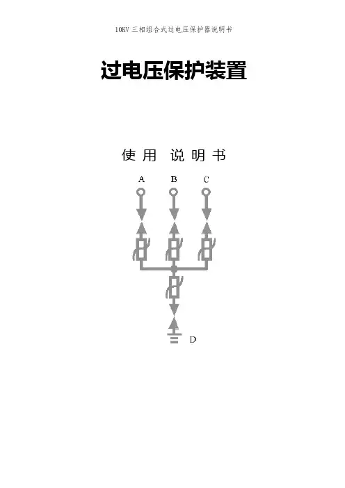
过电压保护装置使用说明书过电压保护装置使用说明一、产品用途三相组合式过电压保护器主要用于发电、供电和用电企业的电力电网中。
用来保护变压器、开关、母线、电动机等电气设备,可限制大气过电压及各种开关引起的操作过电压,对相间和相对地的过电压均能起到可靠的限制作用。
二、结构/特点三相组合式过电压保护器的电气原理如图(1)所示,图中FR为氧化锌非线形电阻,CG为放电间隙,由于采用对称结构,其中任意三个可分别接入A、B、C三相,另一个接地线。
三相组合式过电压保护器具有下面的一些特点:1.用氧化锌非线性电阻和放电间隙的结构,使两者互为保护。
放电间隙使氧化锌电阻的荷电率为零,氧化锌电阻的非线性特性又使放电间隙动作后无续流,放电间隙不再承担灭弧任务,提高了产品的使用寿命。
2.采用四星形接法,对相间和相对地的过电压均能起到可靠的限制作用。
可将相间过电压大大降低,保护的可靠性大为提高。
3.在各种电压波形下放电值均相等,不受各种操作过电压波形的影响,过电压保护值准确,保护性能优良。
4.使用环境温度为-400C~+600C,海拔高度小于2000m。
5. 本产品带脱钩装置,觉有防爆功能。
三、型号说明HB-BOD-□-□/□□-□附加功能使用环境相间距离(mm)持续运行电压(kV)保护对象1.保护对象:D-电动机 ;B-电站; R-并联补偿电容器; O-电机中性点;2.持续运行电压:允许持久地施加在相间及相对地的工频电压有效值;3.外套类型:F硅橡胶外套;4.使用环境:W为户外型,无‘W’只适用于户内;5.附加功能:“J”或“IM”为过电压动作记数器,(只适用于户内型);6.采用高压电缆外引结构,因此,对外引电缆长度“L”及线鼻子孔经“φ”要求,由用户在订货时注明。
四、技术参数表一型号保护对象保护器持续运行电压(kV)有效值保护对象额定电压(kV)有效值工频放电电压(kV)有效值高度mm有效值允许范围HB-D-7.6/131电动机7.66.3 12.48 11.25~15.0186200HB-D-12.7/131 12.7 10.520.6 18.0~25186235HB-B-7.6/131 变压器、母线、发动机、开关线路7.6 6 1412.6~17.5186 235HB-B-12.7/131 12.7 10 23.2 20.88~30.0186235五、外型尺寸图 (见附图)10KV等级以下图形六、试验方法及注意事项1、试验方法:试验原理接线如图(2)所示。
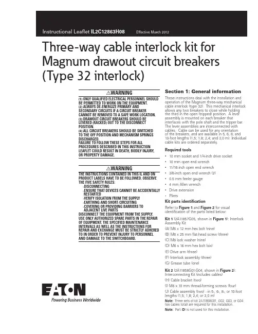
Three-way cable interlock kit for Magnum drawout circuit breakers (Type 32 interlock)I WARNING(1) ONLY QUALIFIED ELECTRICAL PERSONNEL SHOULD BE PERMITTED TO WORK ON THE EQUIPMENT.(2) ALWAYS DE-ENERGIZE PRIMARY AND SECONDARY CIRCUITS IF A CIRCUIT BREAKER CANNOT BE REMOVED TO A SAFE WORK LOCATION. (3) DRAWOUT CIRCUIT BREAKERS SHOULD BE LEVERED (RACKED) OUT TO THE DISCONNECT POSITION.(4) ALL CIRCUIT BREAKERS SHOULD BE SWITCHED TO THE OFF POSITION AND MECHANISM SPRINGS DISCHARGED.FAILURE TO FOLLOW THESE STEPS FOR ALL PROCEDURES DESCRIBED IN THIS INSTRUCTION LEAFLET COULD RESULT IN DEATH, BODILY INJURY, OR PROPERTY DAMAGE.i WARNINGTHE INSTRUCTIONS CONTAINED IN THIS IL AND ON PRODUCT LABELS HAVE TO BE FOLLOWED. OBSERVE THE FIVE SAFETY RULES:-DISCONNECTING-ENSURE THAT DEVICES CANNOT BE ACCIDENTALLY RESTARTED-VERIFY ISOLATION FROM THE SUPPLY-EARTHING AND SHORT-CIRCUITING-COVERING OR PROVIDING BARRIERS TOADJACENT LIVE PARTSDISCONNECT THE EQUIPMENT FROM THE SUPPLY. USE ONLY AUTHORIZED SPARE PARTS IN THE REPAIR OF EQUIPMENT. THE SPECIFIED MAINTENANCE INTERVALS AS WELL AS THE INSTRUCTIONS FOR REPAIR AND EXCHANGE MUST BE STRICTLY ADHERED TO IN ORDER TO PREVENT INJURY TO PERSONNEL AND DAMAGE TO THE SWITCHBOARD.Section 1: General information These instructions deal with the installation andoperation of the Magnum three-way mechanical cable interlock (type 32). This mechanical interlock allows any two breakers to close while holding the third in the open (tripped) position. A lever assembly is mounted on each breaker that interfaces with the pole shaft and the tripper bar. The lever assemblies are interconnected with cables. Cable can be used for any orientationof the breakers, and are available in 5, 6, 8, and 10-foot lengths (1,5; 1,8; 2,4; and 3,0 m). Individual cable kits are ordered separately.Required tools• 10 mm socket and 1/4-inch drive socket• 10 mm open end wrench• 11/16-inch open end wrench• 3/8-inch open end wrench (2)• 0.5 mm feeler gauge• 4 mm Allen wrench• Drive extension• PliersKit parts identificationRefer to Figure 1 and Figure 2 for visual identification of the parts listed below:Kit 1 (2A11857G05, shown in Figure 1): Interlock Assembly Kit(A) M6 x 12 mm hex bolt (nine)(B) M6 x 25 mm flat-head screw (three)(C) M6 lock washer (nine)(D) M6 x 16 mm hex bolt (six)(E) Drive arm (three)(F) Interlock assembly (three)(G) Grease tube (one)Kit 2 (2A11858G01-G04, shown in Figure 2): Interconnecting Kit (includes cables)(H) Cable bracket (two)(I) M6 x 10 mm thread-forming screws (four) (J) Cable assembly (two) - in 5-, 6-, 8-, or 10-foot lengths (1,5; 1,8; 2,4; or 3,0 m)Note: Three sets of kit 2A11858G01, G02, G03, or G04 (six cables total) are required for this installation.Note: Part (D) is not used for this installation.2Instructional Leaflet IL2C12863H08Effective March 2012Three-way cable interlock kit for Magnum drawout circuit breakers(Type 32 interlock)EATON CORPORATION Figure 1. (A)(G)(E)(D)(C)(B)(F)Contents of Kit 1Figure 2. (I)(K)(J)Contents of Kit 2Section 2: Installation of three-waycable interlockProceed with the following 12 steps:Step 1: Remove the front cover by unscrewing the hex-head captive bolts (four for three-pole, six for four-pole) that join the cover to the breaker housing using a 10 mm 1/4-inch drive socket. Then hold the charge handle down approximately 45 degrees to pull off the cover.Step 2: Remove the knockout (a U-shaped tab) from the right side of the front cover using pliers. Carefully file any excess material from the broken edge.Figure 4. Step 2Step 3: Install drive arm (E ) to the right end of the pole shaft using an M6 x 25 mm flat-head screw (B ) and 4 mm Allen wrench. The drive arm should be oriented as shown. Torque to 65-85 in-lbs (7,3-9,6 Nm).3Instructional Leaflet IL2C12863H08Effective March 2012Three-way cable interlock kit for Magnum drawout circuit breakers (Type 32 interlock)EATON CORPORATION Step 4: Reinstall front cover (removed in Step 1). Perform Steps 1 to 4 for each breaker.Step 5: Fasten the interlock assembly (F ) to the drawout cassette’s right-side sheet as shown, using three M6 x 12 mm hex bolts (A ) and lock washers (C ). Torque to 40–50 in-lbs (4,5–5,6 Nm).Step 6: Fasten the cable bracket (H ) to the drawout cassette’s right-side sheet (below the interlock assembly installed in Step 5) as shown, using two M6 x 10 mm thread-forming screws (I ). Torque to 65 – 85 in-lbs (7,3 – 9,6 Nm). Perform Steps 5 to 6 for each breaker.Figure 7. Step 6Step 7:Check the functionality of the interlock assemblies by performing the following two checks. Refer toFigure 8:Check 1:• Fully insert the breaker into its cassette to the CONNECTED position.•Make sure the drive arm (E ) and the interlock assembly’s inner trip arm pass clearance. The teardrop-shaped follower arm of the interlock assembly should engage with the pin on the drive arm. The inner trip arm of the interlock assembly should engage with the tripper bar of the breaker.•Perform this check for each breakerCheck 2:• With the breaker OPEN and CONNECTED, observe the position of the DRIVE (LOWER) LEVER. There should be a 0 – 4 mm gap between the lower right-hand corner of the drive lever and the mounting bracket flange (see Figure 8 Breaker OPEN).•Now CHARGE and CLOSE the breaker. The drive lever should rotate approximately 60 degrees counterclockwise. Thereshould be a 1 – 7 mm gap between the lower left-hand corner of the lever and the interlock assembly flange (see Figure 8 Breaker CLOSED).•If either of these gaps is out of specification, DO NOTCONTINUE THE INSTALLATION. Consult Eaton for additional instructions. To reach an EatonCare representative, call (877) 386-2273.•Perform this check for each breaker.Figure 8. Step 7Step 8: This step will prepare the cables before they are attached to the interlock assembly. Check to be sure that all cables move freely in their cable housing. Each cable should have a long rod end and a short rod end. To perform the cable prep:1. Remove the upper lock nut and spacer tube from both rod ends.2. Remove the compression spring from the short rod.3. Two loose nuts should be positioned on the threads of each rod. Shoulder the lower nut against the rod threads until the nut stops. Using two 3/8” wrenches, tighten the upper nut against the lower nut (see Figure 10).Repeat the above process on both long and short rods on any given cable.4Instructional Leaflet IL2C12863H08Effective March 2012Three-way cable interlock kit for Magnum drawout circuit breakers(Type 32 interlock)EATON CORPORATION Figure 9. Step 8 - Cable AssemblyFigure 10. Step 8 - Cable PrepStep 9: This step describes how to route the cables between breakers. Each breaker should be in the OPEN and DISCHARGED position. When routing cables, adhere to the following recommendations:• 4 inch (102 mm) minimum allowable cable housing bend radius and minimal number of total bends•Use plastic wire ties/clamps to attach cable housing to the structure after installation and adjustment • Do not compress cable housing •Recheck to ensure cables move freelyRefer to T able 1 and Figure 11 for installation details.T able 1. Cable RoutingT ype 32 (Six Cables)From Cassette/Fitting T o Cassette/Fitting 1A3D 1C 2B 2A 1D 2C 3B 3A 2D 3C1BStep 10: This step describes how to attach the cables to the interlock assemblies. Each breaker needs two long rods and two short rods attached. The short (drive) rods will be attached first. 1. Slide the rubber boot toward the tip of the rod.2. Unthread the outer bulkhead nut and slide the nut and lock washer upwards.5Instructional Leaflet IL2C12863H08Effective March 2012Three-way cable interlock kit for Magnum drawout circuit breakers (Type 32 interlock)EATON CORPORATION 3. Slide the smaller diameter portion of bulkhead fitting in to the slot on the cable bracket (see Figure 12).4. Raise cable assembly until threads of the bulkhead fitting show above the slotted hole in the bracket (See Figure 12).5. Insert threaded end of rod into its swivel fitting.6. Bring the bulkhead washer and nut down to the threads and hand-tighten.7. Adjust the two bulkhead nuts to approximately center the fitting on the slot and hand-tighten.8. Replace the rubber boot over end of fitting.9. If short rod is in Position A (see Figure 11):a. Lower threaded rod tip back through swivel.b. Replace spacer tube and compression spring on rod end before sliding the rod tip through the swivel fitting of the lower lever. To aid in sliding the rod tip, grip the nuts that were tightened in Step 8.10. If short rod is in Position C (see Figure 11):a. Replace spacer tube on rod end.b. Replace compression spring on rod end.c. Manually compress the compression spring to replacethe lock nut.11. Replace the lock nut on the rod end.12. Hold the nuts that were tightened in Step 8 and use a 3/8-inch socket or a 3/8-inch open-ended wrench to tighten the lock nut until it touches the spacer tube. Torque to 30-40 in-lbs (3,3-4,5 Nm).Next, the long (driven) rods will be attached. The long rods areattached in the same way as the short rods except they do not use compression springs.Repeat the above processes for all cable ends. At the end of cable installation, the breakers should still be in the OPEN position.Figure 12. Step 10Figure 13. Step 10 - Short Rod Assembly (Position C)Figure 14. Step 10 - Long Rod Assembly (Position B)Step 11: This step describes how to adjust the cables. The initial adjustments are made with all breakers OPEN. The bulkhead nuts for each cable should be set so that the threaded bulkhead fitting is approximately centered on the cable bracket slot. Initial adjustments will be performed on the driven (long) rods.• Check the upper lever on each interlock assembly. There should be about a 1 mm gap between the top of the center slot in the lever and the top of the upper roller.6Instructional Leaflet IL2C12863H08Effective March 2012Three-way cable interlock kit for Magnum drawout circuit breakers(Type 32 interlock)EATON CORPORATION Figure 16. Step 11•If adjustment is needed, use the bulkhead nuts to appropriately adjust the cable housing. •T oo much clearance : adjust both bulkhead nuts to retract cable housing•No clearance : advance cable housing in a similar manner•For additional adjustment length : use bulkhead nuts on other end of cableAt the end of adjustment, adjust the rods using the upper cable nuts (tightened in Step 8) so that all upper levers are in the position demonstrated in Figure 16. Check the function of the mechanical interlock assembly according to the functional tests in the Step 12. Review Steps 3 – 12 and keep adjusting the interlock assembly until it functions correctly.Note: If experiencing difficulty or operating in a confined space, consider using an 11/16-inch flare nut crowfoot wrench drive to perform adjustments.Step 12: Perform the following functional tests and verify that the assembly conforms to all states in T able 2: 1. Open all breakers.2. Charge and close Breaker A . Breakers B and C should not be held in the OPEN condition. Open Breaker A.3. Charge and close Breaker B . Breakers A and C should not be held in the OPEN condition. Open Breaker B.4. Charge and close Breaker C . Breakers A and B should not be held in the OPEN condition. Open Breaker C .5. Charge and close Breakers A and B . Breaker C should be held in the OPEN condition and not respond to a CLOSE attempt (no noise, no contact motion, no spring discharge). Open Breakers A and B .6. Charge and close Breakers B and C . Breaker A should be held in the OPEN condition and not respond to a CLOSE attempt (no noise, no contact motion, no spring discharge). Open Breakers B and C .7. Charge and close Breakers A and C . Breaker B should be held in the OPEN condition and not respond to a CLOSE attempt (no noise, no contact motion, no spring discharge). Open Breakers A and C .g=1mmFigure 17. Breaker ABreaker CBreaker BStep 127Instructional Leaflet IL2C12863H08Effective March 2012Three-way cable interlock kit for Magnum drawout circuit breakers (Type 32 interlock)EATON CORPORATION T able 2. Step 12 LogicA B C 00010001000111001111TR1TR2The mechanical interlock is now appropriately installed and adjusted. To ensure safety, secure the bulkhead nuts and upper cable nuts in proper position by applying sealing wax.If some interlock parts are sticky, use a light amount of the lubricant grease (G ) to reduce the friction. This is ONL Y recommended if needed.Eaton Corporation Electrical Sector1000 Cherrington Parkway Moon Township, PA 15108 United States877-ETN-CARE (877-386-2273) © 2010 Eaton CorporationAll Rights ReservedPrinted in USAPublication No. IL2C12863H08 / Z9270 March 2012PowerChain Management is a registered trademark of Eaton Corporation.All other trademarks are property of their respective owners.Instructional Leaflet IL2C12863H08 Effective March 2012Three-way cable interlock kit for Magnum drawout circuit breakers(Type 32 interlock)Disclaimer of warranties and limitation of liabilityThe information, recommendations, descriptions, and safety notations in this document are based on Eaton Corporation’s (“Eaton”) experience and judgment, and may not cover all contingencies. If further information is required, an Eaton sales office should be consulted.Sale of the product shown in this literature is subject to the terms and conditions outlined in appropriate Eaton selling policies or other contractual agreement between Eaton and the purchaser. THERE ARE NO UNDERSTANDINGS, AGREEMENTS, WARRANTIES, EXPRESSED OR IMPLIED, INCLUDING WARRANTIES OF FITNESS FOR A PARTICULAR PURPOSE OR MERCHANTABILITY, OTHER THAN THOSE SPECIFICALL Y SETOUT IN ANY EXISTING CONTRACT BETWEEN THE PARTIES. ANY SUCH CONTRACT STATES THE ENTIRE OBLIGATION OF EATON. THE CONTENTS OF THIS DOCUMENT SHALL NOT BECOME PART OF OR MODIFY ANY CONTRACT BETWEEN THE PARTIES. In no event will Eaton be responsible to the purchaser or user incontract, in tort (including negligence), strict liability, or otherwise for any special, indirect, incidental, or consequential damage or loss whatsoever, including but not limited to damage or loss of use of equipment, plant or power system, cost of capital, loss of power, additional expenses in the use of existing power facilities, or claims against the purchaser or user by its customers resulting from the use of the information, recommendations, and descriptions contained herein.The information contained in this manual is subject to change without notice.。
三相组合式复合外套金属氧化物避雷器产品简介西安神电电器有限公司中国·西安目录三相组合式复合外套金属氧化物避雷器1、概述 (1)2、产品型号说明 (1)3、正常使用条件 (2)4、主要技术参数 (2)5、外形结构及安装尺寸 (4)6、接线方式……………………………………………………………………………10带放电记录仪三相组合式复合外套金属氧化物避雷器1、概述 (11)2、产品型号说明 (11)3、主要技术参数 (11)4、外形结构及安装尺寸 (12)12 5、接线方式…………………………………………………………………………极间过电压保护器1、概述 (13)2、主要技术参数 (13)3、接线方式……………………………………………………………………………13预防性检测及用户须知1、预防性检测 (14)2、用户须知 (15)三相组合式复合外套金属氧化物避雷器一、概述三相组合式复合外套金属氧化物避雷器在对相地之间的过电压提供保护的同时,又对相间过电压提供保护。
本产品结构新颖,外形组合灵活多变,有效的利用和缩减了使用空间。
技术性能合理可靠,保护水平满足 GB 11032-2000《交流无间隙金属氧化物避雷器》、JB/T 10496-2005《交流三相组合式无间隙金属氧化物避雷器》、JB/T ××××-××××《交流三相组合式有串联间隙金属氧化物避雷器》(报批稿)、JB/T 9672.2-2005《交流系统用有串联间隙金属氧化物避雷器》和 DL/T 620-1997《交流电气装置的过电压保护和绝缘配合》的标准要求。
并在国家绝缘子避雷器质量监督检验中心通过了全面的型式试验,已广为电力、石化、铁道、煤碳等系统选用。
二、产品型号说明本产品型号编制方法严格按照 JB/T 8459-1996《避雷器产品型号编制方法》中的 4.2.3.1 条“三相组合式金属氧化物避雷器”标准要求编制,具体如下:外形结构(代号)征数字设计序号使用场所结构特征(kA)产品型式:YH—表示复合外套金属氧化物避雷器结构特征:W—表示无间隙C—表示串联间隙使用场所:S—表示配电用R—表示并联补偿电容器用Z—表示电站用D—表示电机用特征数字:○1 表示相-相的特征数字○2 表示相-地的特征数字外形结构:A—表示A 型B—表示B 型 C—表示C 型J—表示带放电记录仪三、正常使用条件a. 适用于户内、外;b. 环境温度-40℃~+40℃;c. 海拔高度不超过2600m;d. 电源频率不小于48Hz,不大于62Hz;e. 长期施加在避雷器端子间的工频电压应不超过避雷器的持续运行电压(无间隙型)或额定电压(带串联间隙型);f. 地震烈度8 度及以下地区;g. 最大风速不超过35m/s; h. 重污秽及以下地区。

完整的系统过电压保护解决方案!超宽脱离短路电流范围300A~100KABOD自动脱离式、大容量免维护三相组合式过电压保护装置说明书3~10KV系统BOD-I型:普通型BOD-II型:有通讯接口上海合凯电力保护设备有限公司产品简介上海合凯电力保护设备有限公司是凯立集团所属的制造三相组合式过电压保护器的专业子公司,本公司生产的TBP自上世纪90年代初期诞生以来,已为我国的电力事业作出了巨大贡献。
但是,由于认识和实验技术上的局限,早期TBP以及后来其它企业派生出的各种类型的三相组合式过电压保护器都没有成熟有效的故障退出手段,以至于,在系统谐振或者其他恶劣条件下,保护器本身发生崩溃,进而引发开关柜内相间短路,给用户造成生产和物质上的损失,有时还有较大的间接经济损失。
无论是用户还是保护器制造厂家都非常清楚的看到目前过电压保护方案存在的不足,但是苦于没有切实有效的解决办法,只能忍受现状。
凯立集团一直坚持研发为主的宗旨,不断的完善和充实实验设备,目前已具备我国最大的200KA 短路电流的实验条件,通过一年多的试制,终于完成了过电压保护器的脱离技术,并获得了实用新型专利。
目前由上海合凯电力保护设备有限公司生产的BOD,命名为:大容量、自脱式、免维护、三相过电压保护装置,添加了保护功能、运行检测功能、故障自动脱离功能,结束了早期单纯的三相组合式过电压保护器的不完善之处,可在内部发生击穿时,快速自动脱离系统,由于实现了自动脱离功能,因此,也免去了定期检测保护器的工作,同时整合了光电耦合技术,增加了脱离器状态检测、保护装置动作计数、网络通信接口等功能,真正实现了完整的过电压保护解决方案,并与现场自动化管理接轨。
完整的系统过电压保护解决方案1.传统的过电压保护解决方案●只针对过电压进行限制,没有自身故障退出功能;●当保护器本体故障时,一般会引发柜内相间短路,造成柜体爆炸。
过电压保护元件的性能总是要蜕变的:i.频繁的系统操作过电压会导致保护元件逐渐老化,最终被击穿;ii.系统谐振过电压会导致保护元件极速老化,或者直接击穿;iii.系统在快速(<1ms)切除短路故障时,回路电感(尤其是电源变压器)储存的能量会导致保护元件极速老化,或者直接击穿;iv.保护器若漏气或受潮,会导致保护元件性能快速蜕变,极易造成内部闪络或击穿。

阻容三相复合式过电压保护器使用说明书一型号说明二产品用途SYB-ZR三相复合式过电压保护器是针对现行各类过电压保护器保护弱点而设计的新一代保护装置,其将阻容吸收器和避雷器的功能有机地结合在一起。
主要用于吸收真空断路器、真空接触器在开断感性负载时产生的高频操作过电压,同时具有吸收大气过电压及其它形式的暂态冲击过电压的功能。
可广泛地用于真空断路器操作的电动机、电抗器、变压器等配电线路中。
三产品优点及特点:本产品内部为氧化锌阀片和电阻电容的有机结合,兼有传统氧化锌型保护器和阻容吸收器的优点,又从根本上克服了单纯氧化锌阀片型保护器和阻容吸收器各自不可避免的缺点。
性能优异,安全可靠。
A 本产品保护特性如下:(1) 当系统在正常运行中,保护器阻容回路中的电阻仅通过µA级电流,电容回路不接入系统,不会对系统提供附加接地电容电流,有利于整体电路设计以保证系统稳定工作,且减轻了高次谐波对电容的损伤。
(2)当系统出现幅值较小的过电压时,阻容吸收器工作,吸收高频过电压,对所保护的设备提供真正的弱绝缘保护。
(3)当系统过电压幅值较大(如:雷电过电压)时,避雷器回路工作,释放高幅值能量,将过电压幅值限制在一定范围内,以保护设备的绝缘不受损坏。
B 本产品与其它过电压保护产品对比其性能优点如下:(1) 具有阻容吸收器和金属氧化物避雷器(或过电压保护器)的双重功能。
(2)阻容回路,特别适用于开断感性负载产生的高频操作过电压的保护。
(避雷器无此功能)(3)用大通流氧化锌非线性阀片限制大气过电压和高幅值操作过电压。
(阻容吸收器无此功能)(4)具有相间和相地过电压保护功能。
(单只氧化锌型保护器只有相-地保护功能)-1-四产品技术参数产品技术参数见表1及表2表1配电用保护器电气特性参数(相-相,相-地)系统标称电压kV(有效值) 3 6 10 35保护器额定电压 3.8 7.6 12.7 42阻容回路及电容参数 自动接入电网工频电压 kV±10% 5 10 17 58 额定电容 μF0.1 0.1 0.1 0.050.2 0.2 0.2 0.1 验收时极间耐压10s工频电压 kV(有效值) 6 17.3 22.5 60直流电压 kV 12 34.5 45 120无间隙避雷回路 直流1mA参考电压 kV不小于7.5 15 25 84 相-相7.2 14.4 24 73 相-地 雷电冲击电流残压kV(峰值)不大于13.5 27.0 45.0 150.0 相-相13.5 27.0 45.0 134.0 相-地 操作冲击电流残压11.5 23.0 38.3 134.0 相-相11.5 23.0 38.3 114.0 相-地串联间隙避雷回路工频放电电压 kV(有效值)不小于 8.0 16.0 26.0 80.0 1.2/50冲击放电电压kV(峰值)不大于12 24 41 124 雷电冲击电流残压 12 24 41 124 操作冲击电流残压 10.2 20.4 35 105表2电机用保护器电气特性参数(相-相,相-地)系统标称电压kV(有效值) 3 6 10保护器额定电压 3.8 7.6 12.7阻容回路及电容参数 自动接入电网工频电压 kV±10% 4.0 8.0 13.5 额定电容 μF0.1 0.1 0.10.2 0.2 0.2 验收时极间耐压10s工频电压 kV(有效值) 6.0 17.3 22.5直流电压 kV 12.0 34.5 45.0无间隙避雷回路 直流1mA参考电压 kV不小于7.0 14.0 23.2 相-相5.7 11.2 18.6 相-地 雷电冲击电流残压kV(峰值)不大于11.6 23.3 38.7 相-相9.5 18.7 31.0 相-地 操作冲击电流残压9.4 18.7 31.0 相-相7.6 15.0 25.0 相-地串联间隙避雷回路工频放电电压 kV(有效值)不小于 7.5 15.0 25.01.2/50冲击放电电压kV(峰值)不大于9.5 18.7 31.0雷电冲击电流残压 9.5 18.7 31.0操作冲击电流残压 7.6 15.0 25.0注:1、电容器极间耐压试验,工频电压和直流电压任选一种,加压位置为a-c、b-n。

SHK-XHG消弧及过电压保护装置使用说明书上海合凯电力保护设备有限公司SHK-XHG消弧及过电压保护装置使用说明书一、SHK-XHG装置的构成及主要元件的作用SHK-XHG装置(以下简称装置)的柜体结构如图1所示。
装置的主要元件及其作用如下:图11.电压互感器为装置提供被保护系统的二次电压和辅助二次电压信号,亦可为继电保护装置和计量仪表提供电压信号。
2.微机控制器根据电压互感器提供的信号,判断故障类别(PT断线、金属接地、弧光接地)和相别,向控制室或上位机发出故障通讯信号,当发生弧光接地时向故障相真空接触器发出合闸命令。
3.交流真空快速接触器在接到微机控制器的动作命令后快速完成合闸动作,使弧光接地故障快速转化为金属性接地。
4.三相组合式过电压保护器SHK-TBP将相对地和相与相之间的各种过电压限制在设备绝缘允许的较低的水平。
5.高压隔离开关用来控制装置的投运和退出,在装置需要检修或调试时与系统隔离并形成明显的断开点。
6.高压限流熔断器FU当由于装置内部故障或人员误接线等原因导致装置误判断时,可在1~2ms之内快速实现截流,并将装置退出,避免造成两相短路的后果。
7.零序CT和接地电流表在装置动作时,通过接地电流表可较准确地读出系统的接地电容电流。
二、装置的型号、主要技术参数及一次系统接线1.装置的型号及其意义装置的型号为:SHK-XHG—□—□/ □装置的额定电流装置的额定电压B:标准配置型,具有消弧及过电压保护功能F:附加型,具有具有消弧、消谐及过电压保护功能Q:加强型,具有具有消弧、消谐、选线及过电压保护功能P:简化型,具有消谐、选线及过电压保护功能2.装置的主要技术参数额定电压(kV):6、10、24、35额定电流(A):31.5、50、63、80、100、125、160、200、250、3153. 装置的一次原理接线图装置的一次原理接线如图2所示图2三、装置的工作原理正常运行时微机控制器不断检测PT提供的电压信号,一旦系统发生单相故障,PT辅助二次的开口三角电压迅速升高,微机控制器立即启动中断,并根据PT二次电压的变化,判断故障类型和相别。
GX系列组合式过电压保护器说明书杭州共享电力设备有限公司目录一、产品概述........................................................ 错误!未定义书签。
二、型号说明及外型图........................................ 错误!未定义书签。
2.1型号说明 ........................................................ 错误!未定义书签。
2.2外形图............................................................. 错误!未定义书签。
三、技术参数........................................................ 错误!未定义书签。
3.1 GX1系列过电压保护器主要技术参数 ..... 错误!未定义书签。
3.2 GX2系列过电压保护器主要技术参数 ..... 错误!未定义书签。
四、安装注意事项................................................ 错误!未定义书签。
五、使用与维护.................................................... 错误!未定义书签。
5.1使用环境: ...................................................... 错误!未定义书签。
5.2日常维护: ...................................................... 错误!未定义书签。
5.3注意事项: ...................................................... 错误!未定义书签。
三相组合式复合外套金属氧化物避雷器产品简介西安神电电器有限公司中国•西安目录三相组合式复合外套金属氧化物避雷器1、概述 (1)2、产品型号说明 (1)3、正常使用条件 (2)4、主要技术参数 (2)5、外形结构及安装尺寸 (4)6、接线方式 (10)带放电记录仪三相组合式复合外套金属氧化物避雷器1、概述 (11)2、产品型号说明 (11)3、主要技术参数 (11)4、外形结构及安装尺寸 (12)5、接线方式 (12)极间过电压保护器1、概述 (13)2、主要技术参数 (13)3、接线方式 (13)预防性检测及用户须知1、预防性检测 (14)2、用户须知 (15)三相组合式复合外套金属氧化物避雷器—、概述三相组合式复合外套金属氧化物避雷器在对相地之间的过电压提供保护的同时,又对相间过电压提供保护。
本产品结构新颖,外形组合灵活多变,有效的利用和缩减了使用空间。
技术性能合理可靠,保护水平满足GB 11032-2000《交流无间隙金属氧化物避雷器》、JB/T 10496-2005《交流三相组合式无间隙金属氧化物避雷器》、JB/T XXXX-XXXX《交流三相组合式有串联间隙金属氧化物避雷器》(报批稿)、JB/T 9672. 2-2005《交流系统用有串联间隙金属氧化物避雷器》和DL/T 620-1997《交流电气装置的过电压保护和绝缘配合》的标准要求。
并在国家绝缘子避雷器质量监督检验中心通过了全面的型式试验,已广为电力、石化、铁道、煤碳等系统选用。
二、产品型号说明木产品型号编制方法严格按照JB/T 8459-1996《避雷器产品型号编制方法》中的4. 2. 3. 1条“三相组合式金属氧化物避雷器”标准要求编制,具体如下:YH产品型式:表示复合外套金属氧化物避雷器结构特征:W—表示无间隙C—表示串联间隙使用场所:S—表示配电用R—表示并联补偿电容器用Z—表示电站用D—表示电机用特征数字:①表示相-相的特征数字②表示相-地的特征数字外形结构:A—表示A型B—表示B型C—表示C型J—表示带放电记录仪三、正常使用条件a.适用于户内、夕卜;b.环境温度-40°C〜+40°C;c.海拔高度不超过2600m;d.电源频率不小丁48Hz,不大丁62Hz;e.长期施加在避雷器端子间的工频电压应不超过避雷器的持续运行电压(无间隙型)或额定电压(带串联间隙型);f.地震烈度8度及以下地区;g.最大风速不超过35m/s; h.重污秽及以下地区。
SHK-KX开关消弧及过电压保护装置使用说明书上海合凯电力保护设备有限公司SHK-KX 开关消弧及过电压保护装置使用说明书一、 SHK-KX 装置的构成及主要元件的作用SHK-KX 装置(以下简称装置)的柜体结构如图1所示。
装置的主要元件及其作用如下:1203023456789101112132300145014181516171000图11、 消弧智能控制器2、快速手车断路器3、专用PT 手车4、电压互感器5、PT 静触头盒 6、过电压保护装置 7、穿墙套管 8、绝缘子 9、断路器触头盒 10、电缆穿墙套管 11、高压电缆 12、接地排 13、接地孔 14、电流互感器 15、一次系统牌 16、观察窗 17、铭牌 18、电流表1、手车式电压互感器为装置提供被保护系统的二次电压和辅助二次电压信号。
2、微机控制器根据电压互感器提供的信号,判断故障类别(PT 断线、金属接地、弧光接地)和相别,向控制室或上位机发出故障信号,当发生弧光接地时在20ms 之内向故障相真空接触器发出动作命令。
3、交流真空快速手车式断路器在接到微机控制器的动作命令后的10ms 之内完成合闸动作,使弧光接地故障在15ms 之内快速转化为金属性接地。
装置动作后,允许1250A 的电容电流连续通过至少2小时以上,用户可以在完成转移负荷的倒闸操作之后再处理故障线路。
4、三相组合式过电压保护器TBP将相对地和相与相之间的各种过电压限制在设备绝缘允许的较低的水平。
5、零序CT 和接地电流表在装置动作后,通过接地电流表可较准确地读出系统的接地电容电流,在装置动作期间,如果健全相又出现弧光接地时,通过检测零序CT 二次电流的突变,控制器发出跳闸指令,断路器在5ms 内分闸。
二、 装置的型号、主要技术参数及一次系统接线1. 装置的型号及其意义装置的型号为: SHK -KX -□-□2. 装置的主要技术参数额定电压:3、6、10、35kV 额定电流:1250A3. 装置的一次原理接线图装置的一次原理接线如图2所示。
描述:三相组合式过电压保护器(TBP)是一种新型的过电压保护器,由于氧化锌非线性电阻和放电间隙串联组成。
摘要:三相组合式过电压保护器(TBP)是一种新型的过电压保护器,由于氧化锌非线性电阻和放电间隙串联组成。
1、引言:我国避雷器产品的发展经历了变通阀式SIC避雷器、磁吹SIC避雷器、无间隙氧化锌避雷器(MOA)三代。
由于MOA具有结构简单、体积小、通流量大、保护性能及稳定性能好等优点,从而逐步取代了传统SIC避雷器,大量应用于发电、供电和用电企业的电力电网中。
由于MOA没有间隙,不能隔离运行电压,实际上相当于一个非线性电阳元件(发热元件),长年累月地接在电网上承受着各种电压应力,产生严重的老化现象。
MOA由阻片老化后,由于伏安特性曲线的变化,MOA的热稳定点将发生偏移,使得电阻片的热稳定工作点的温度上升,U 1mA 降低,这就意味着荷电率(持续运行相电压峰值和U1mA 的比值)增高。
一旦U 1mA 接近持续运行电压峰值,而且电网电压波动时间较长,超过了MOA工频电压耐受时间特性限定的参数,就会导致MOA热崩溃。
三相组合式过电压保护器(TBP)是一种新型的过电压保护器,由于氧化锌非线性电阻和放电间隙串联组成。
它保留了MOA的优良性能,在电网正常运行时又通过间隙把MOA从电网上隔离开来,避免长期接在电网上承受着各种电压应力,产生老化现象。
目前,电力行业和用电企业在35KV、10KV、6KV系统中大量选用三相结合式过电压保护器(TBP)用来保护变压器,电气开关特性元件,母线等电气设备,对限制大气过电压各种真空开关的操作过电压以及相对相间和相对地间的过电压起到可靠限制保护作用。
2、三相组合式过电压保护器的结构特点三相组合式过电压保护器的电气原理图如图1。
图中FR为氧化锌非线性电阻,CG为放电间隙,采用了对称结构,其中任意三相可分别接A、B、C三相,另一接地。
三相结合式过电压保护器与传统SIC避雷器、无间隙氧化锌避雷器(MOA)相比,具有以下特点:⑴、采用氧化锌非线性电阻和放电间隙相结合的结构,使两者互为保护。
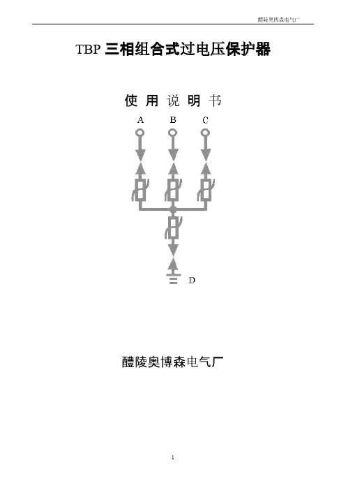
TBP三相组合式过电压保护器使用说明书醴陵奥博森电气厂一、用途三相组合式过电压保护器是一种新型的过电压保护器,主要用于发电、供电和用电企业的电力电网中。
用来保护变压器、开关、母线、电动机等电气设备,可限制大气过电压及各种开关引起的操作过电压,对相间和相对地的过电压均能起到可靠的限制作用。
型号说明:1.保护对象:A-电动机;B-发电机、变压器、母线线路、开关;C- 并联补偿电容器;O-电机中性点;2.持续运行电压:允许持久地施加在TBP相间及相对地的工频电压有效值;3.外套类型:F硅橡胶外套,无‘F’为瓷外套;4.使用环境:W为户外型,无‘W’只适用于户内;5.附加功能:“IM”为产品带过电压动作记录仪(只适用于户内型35KV);“J”为产品带过电压动作记数器(只适用于户内型10KV及以下电压);J为产品带JS-8计数器(只适用于系统电压为35KV户外型TBP),6.表二中型号除“W2”为不带高压电缆引出外,其余型号均采用高压电缆外引结构。
因此,对外引电缆长度“L”及线鼻子孔径“Φ”要求,由用户在订货时注明。
二、结构/特点三相组合式过电压保护器的电气原理如图(1)所示,图中FR为氧化锌非线形电阻,CG为放电间隙,由于采用对称结构,其中任意三个可分别接入A、B、C三相,另一个接地线。
三相组合式过电压保护器与现行过电压保护器相比,具有其它同类产品不可比拟的特点。
1.采用氧化锌非线性电阻和放电间隙相组合的结构,使两者互为保护。
放电间隙使氧化锌电阻的荷电率为零,氧化锌的非线性特性又使放电间隙动作后立即熄弧,无续流、无截波,放电间隙不再承担灭弧任务,提高了产品的使用寿命。
2.在各种电压波形下放电值均相等,不受各种操作过电压波形的影响,过电压保护值准确,保护性能优良。
3.采用四星形接法,对相间和相对地的过电压均能起到可靠的限制作用。
可将相间过电压大大降低,与常规避雷器相比,相间过电压降低了很多,保护的可靠性大为提高。